

Sonic Frontiers SFD-1 Owners manual
OWNER’S MAN U A L
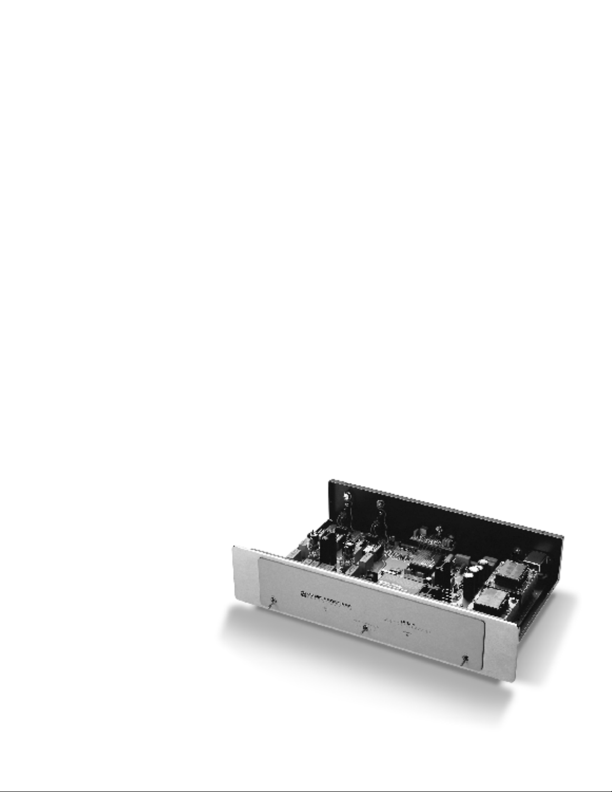
THE SONIC FRONTI ERS S FD-1 DI GI TAL PR OCESSO R
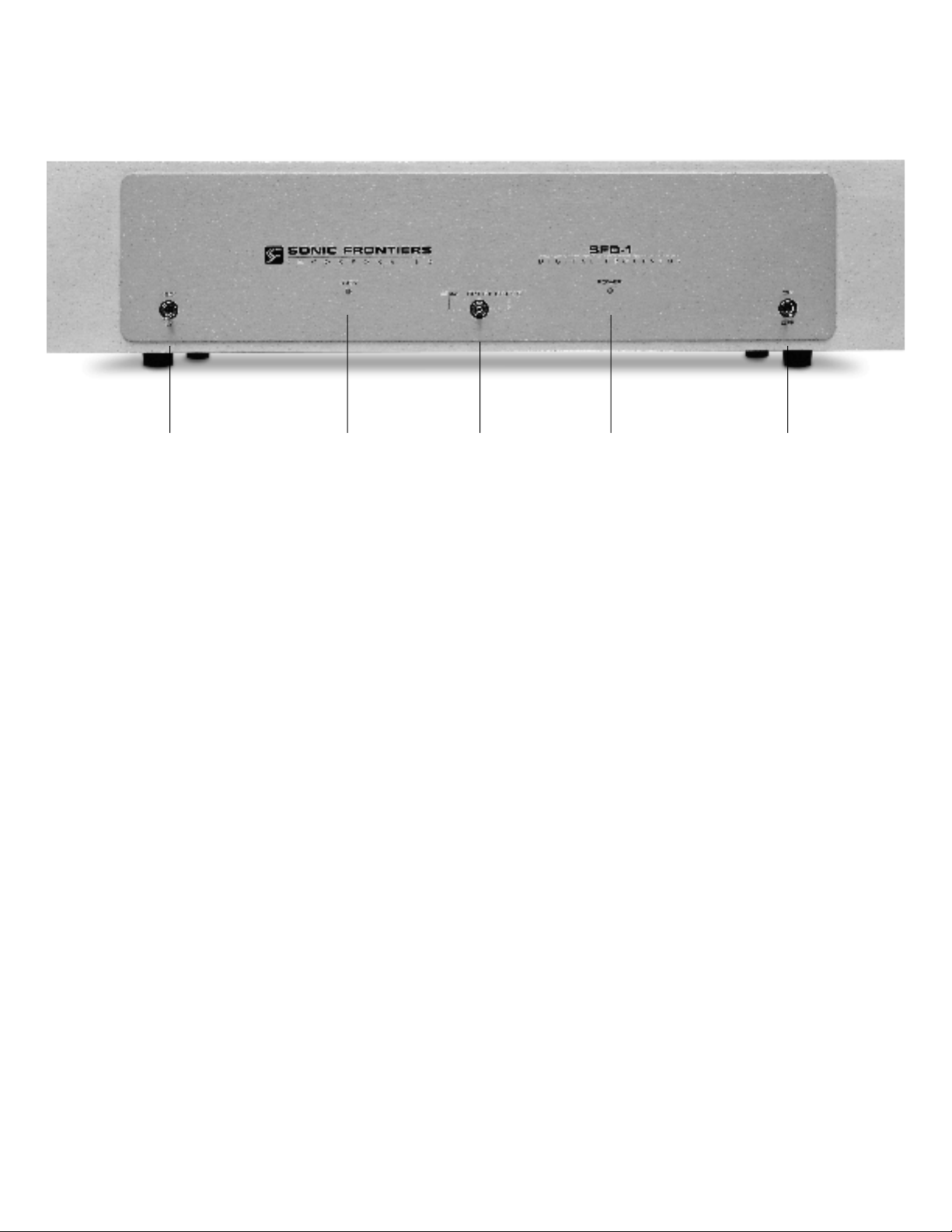
A B C D E
CONTROL FUNCTIONS AND CONNECTIONS
A
-Phase Control Switch - This toggle switch allows the user
to invert the system phasing easily and safely. When the switch
is in the 0° position the SFD-1 will put out a normal or noninverted signal in relation to the signal being received from the
source. When the switch is in the 180° position the SFD-1 will
put out an inverted version of the signal as compared to that
being received from the source. This feature offers a convenient
method of correcting source material which was recorded “out
of absolute phase” or to counteract for a component in your
system such as a preamplifier, power amplifier or signal connection which inverts phase.
B - Signal Locking Indicator LED - This LED will light when
an operational digital source is selected.
NOTE: Depending on the source or transport being used in
conjunction with the SFD-1, it may be necessary to have the
source unit in the “play” mode and the SFD-1 receiving the digital transmission before the LED will light.
D
-Power Indicator LED - This LED will light when the Power
Switch (E) is in the ON position and the SFD-1 is receiving
p o w e r .
E - Power Switch - This toggle switch, when switched to the
ON position, allows the SFD-1 to receive power, rendering the
SFD-1 operational as indicated by the Power Indicator LED (D).
When the switch is in the OFF position the SFD-1 is not receiving power and is not operational.
C - Input Selector Switch - This 3 position toggle switch
selects between the three digital inputs located on the back of
the SFD-1: Toslink (Plastic Fibre) Optical, RCA Coaxial Cable
and ST (Glass Fibre) Optical. A connection to all 3 inputs may
be made from 3 separate sources. The Signal Locking
Indicator LED (B) will light when the source is activated in conjunction with the input chosen by this switch.
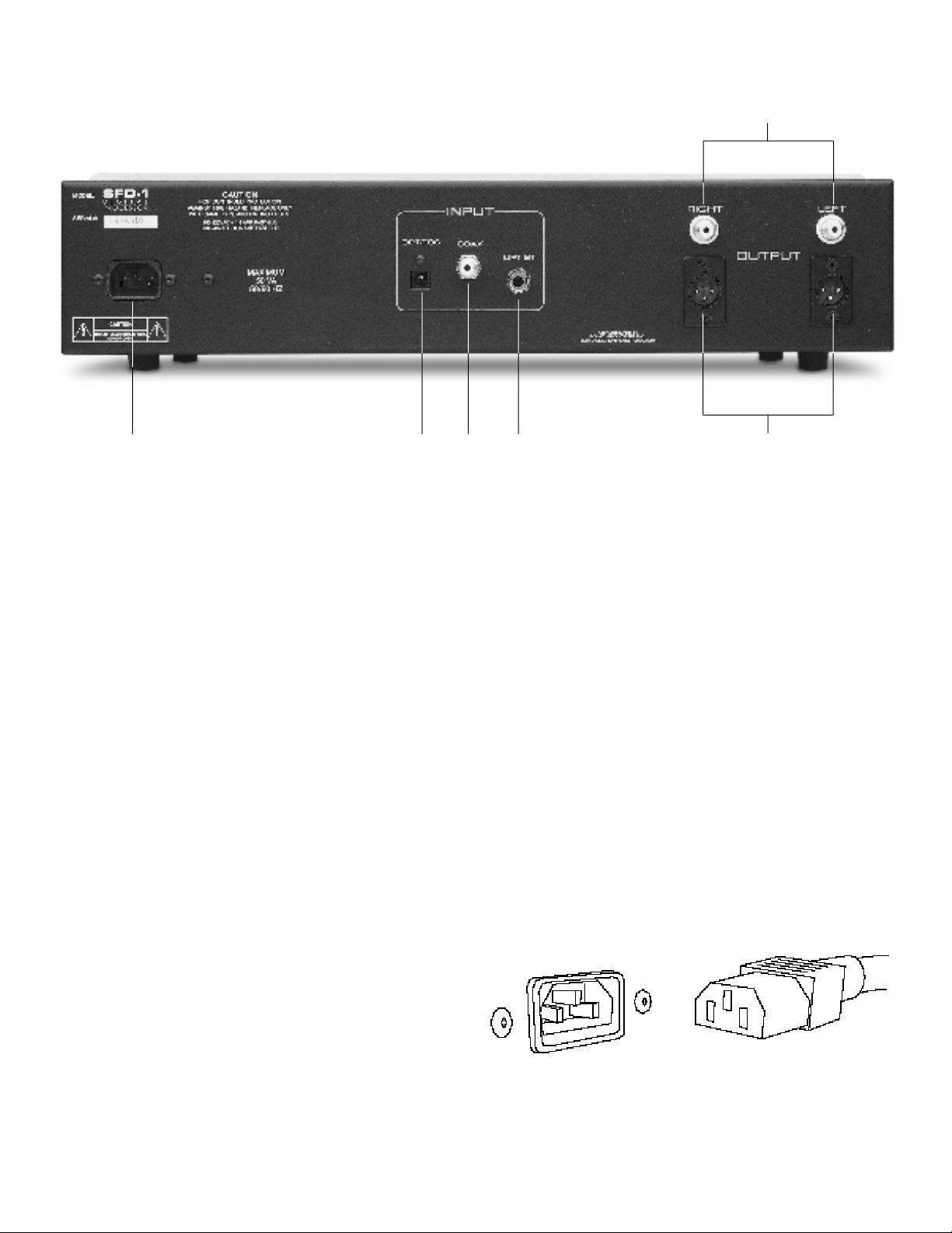
F G H I J
K
F - Detachable Power Cord Socket - Plug the Detachable
Power Cord into this socket (see Figure 1). The SFD-1 is factory
set for the correct operating voltage for the area in which it is
sold (see shipping box for voltage setting). If a different operating voltage is required, please contact an authorized Sonic
Frontiers dealer, distributor or the factory directly.
G - Toslink (Plastic Fibre) Optical Input - This input will
accept a digital connection from a digital source’s Toslink
(Plastic Fibre) Optical digital output (see Figure 3).
H - RCA Coaxial Cable Input - This input will accept a
digital connection from a digital source’s RCA - S/PDIF Coaxial digital output (see Figure 3). The RCA - S/PDIF Coaxial cable impedance should be 75 ohms.
I - ST (Glass Fibre) Optical Input - This input will accept a
digital connection from a digital source’s ST (Glass Fibre) Optical digital output (see Figure 3). This connection type is considered best for optimum performance and sound quality; if your
source unit has this type of digital output we recommend it’s use.
J - Left and Right Channel Balanced XLR Audio
Output Connectors - These are balanced audio outputs
and should be used when connecting the SFD-1 to the
balanced audio inputs of a line level preamplifier, control
amplifier, integrated amplifier or receiver, if these units are so
equipped (see Figure 4). (Left channel output of the SFD-1connects to the left channel input of control unit and right channel
output of the SFD-1 to the right channel input of control unit.)
K - Left and Right Channel RCA Single-Ended Audio
Output Connectors - If the balanced inputs are not applic-
able for use, the RCA single-ended (unbalanced) audio outputs
should be used when connecting the SFD-1 to the RCA
single-ended audio inputs of a line level preamplifier, control
amplifier, integrated amplifier or receiver. (Left channel output
of the SFD-1connects to the left channel input of control unit
and right channel output of the SFD-1 to the right channel input
of control unit.)
Figure 1 - Align socket pins to corresponding holes and push together firmly.
 Loading...