

Page 1
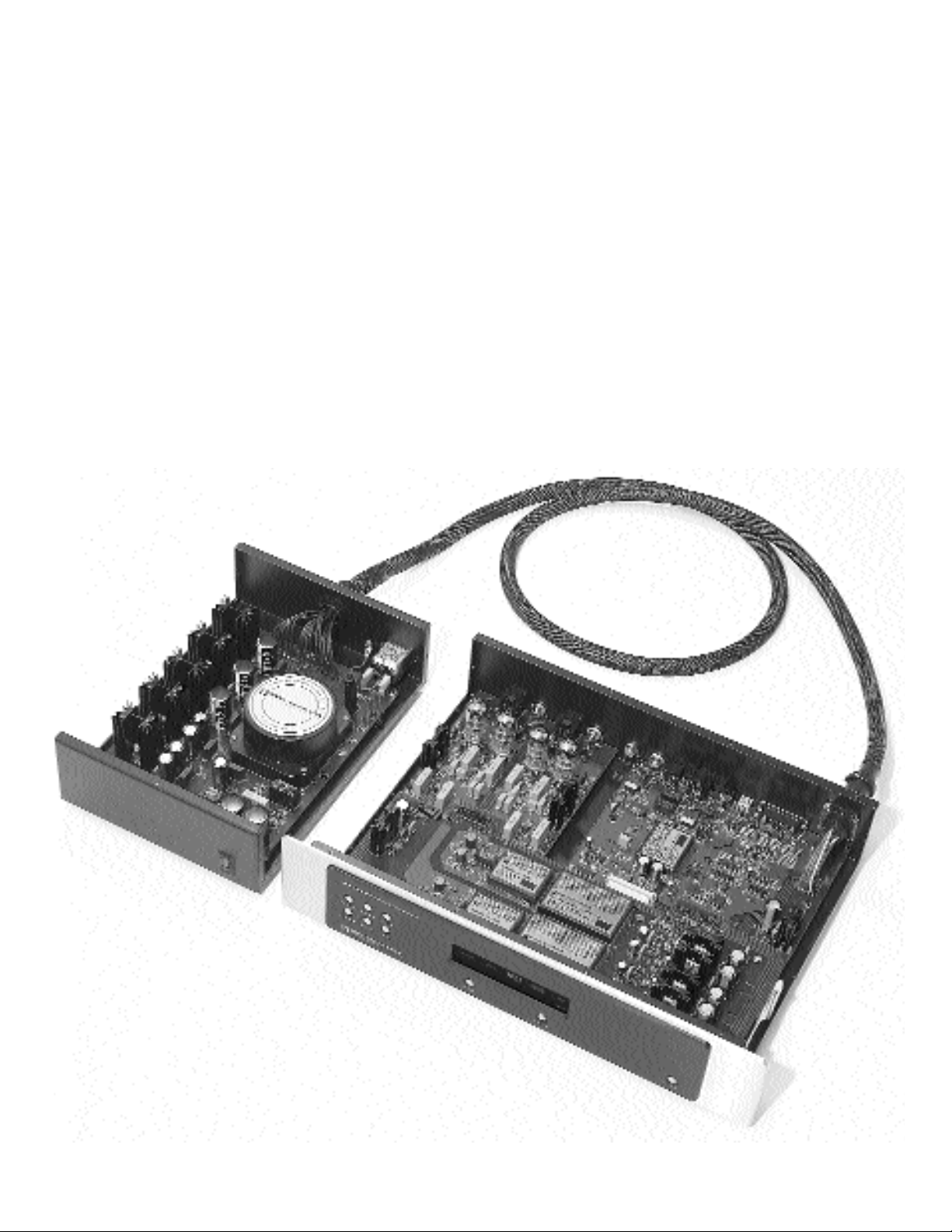
S O N I C
PROCESSOR 3 D I G I TAL PROCESSOR
F R O N T I E R S
O P E R ATING MANUAL
Page 2

OPERATING MANUAL FOR THE SONIC FRONTIERS
PROCESSOR 3 DIGITAL PROCESSOR
We at Sonic Frontiers hope you will derive many years of listening pleasure with your
new Processor 3 Digital Processor. This Operating Manual contains important information
regarding the operation and care of this product. Be sure to read this manual carefully and
follow these instructions in order to keep it performing and sounding its best. Please contact
Sonic Frontiers if you have any questions - a Customer Service Representative will be
pleased to assist you.
C O N T E N T S
Unpacking ........................................................................................................1
Operation, Connection and Control Diagrams ........................................................2
Control and Connection Functions ........................................................................3
Processor Set-up ................................................................................................5
Tube Insertion ....................................................................................................5
Chassis Placement ..............................................................................................6
Connecting External Equipment ............................................................................6
Power Connections ............................................................................................6
Powering On and Startup Procedures ....................................................................7
Trouble Shooting ................................................................................................8
Tube Replacement ..............................................................................................8
Fuse Location ....................................................................................................8
Safety Instructions................................................................................................9
Warranty..........................................................................................................9
Technical Specifications ....................................................................................10
A Note With Regards to HDCD®........................................................................10
This symbol is intended to alert the user to the presence of uninsulated “dangerous voltages” within the product’s enclosure that may be of sufficient magnitude
to constitute a risk of electric shock to persons.
This symbol is intended to alert the user to the presence of important
operating and maintenance (servicing) instructions in the literature accompanying the appliance.
Page 3

1
U N P A C K I N G
At this point we assume that you have successfully opened the box flaps and found this manual.
These boxes were designed to ensure the safe transport of the Processor 3. Sonic Frontiers strongly
recommends the storage of these boxes in a safe dry place. In the event that the Processor 3 may
have to be shipped in the future, the original boxes are the best means for the protection and safety
of the product during transportation.
Here is a chart listing what you will find in the box:
Tube Complement 4 - 6922
Phillips Screwdriver 1
Screws 30
Power Cord 1
Cotton Gloves 1 pair
Extra Fuses 2
Processor 3 Digital Processor 1
Processor 3 Power Supply 1
Processor 3 Top Cover 1
Power Supply Top Cover 1
Warranty Card 1
Operating Manual 1
If after your inspection of the contents there is a discrepancy, contact your dealer or Sonic Frontiers
immediately.
Page 4
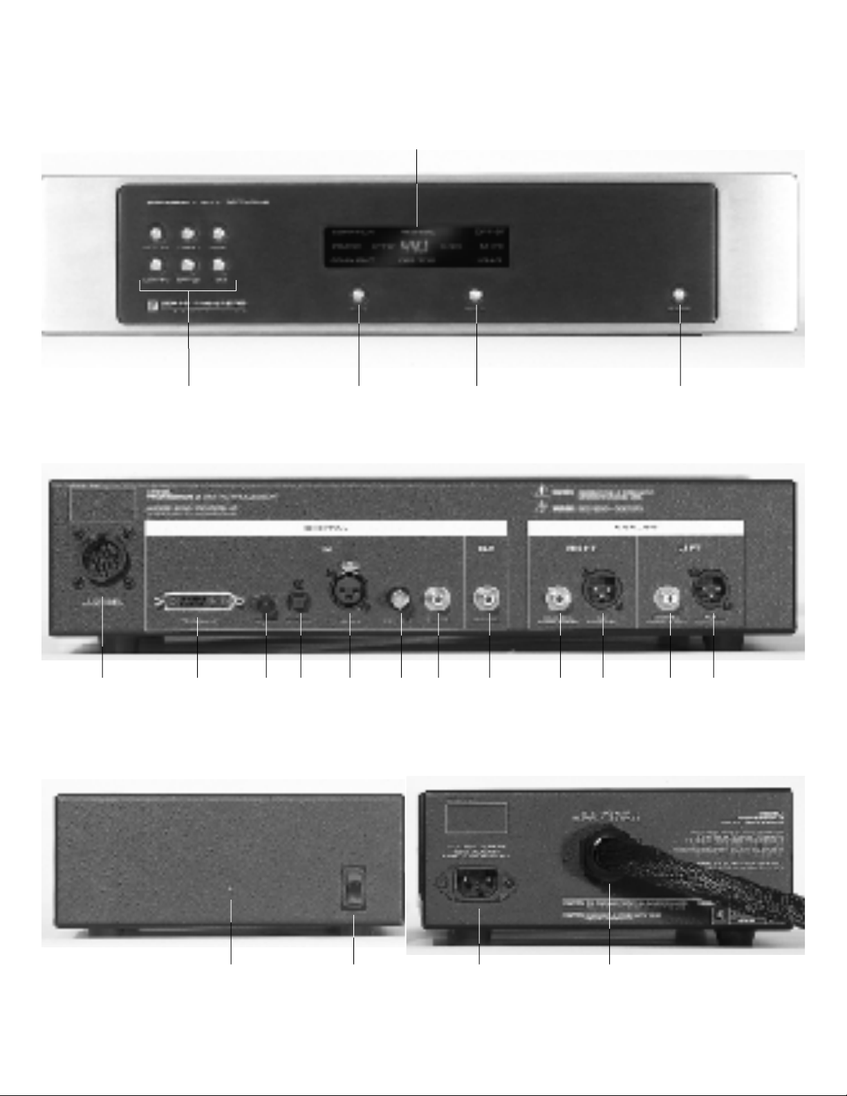
OPERATION, CONNECTIONS AND CONTROL FUNCTIONS
2
DISPLAY WINDOW
A B C D
Figure 1
E F G H I J K L M N O P
Figure 2
Q R S T
Figure 3
Page 5

3
CONTROL AND CONNECTION FUNCTIONS
F R O N T P A N E L
A - Input Buttons (6 - COAX-RCA, AES/EBU, OPT-ST,
COAX-BNC, OPT-TOS, I
2
S • e)
These buttons will select an input signal connected
to one of the six Inputs on the rear of the Processor 3. When
selected, the Display Window will light the selected input.
B - Phase Button - This button allows the user to invert the
system phase polarity by 180˚ (relative to the input signal) easily and safely. Depending upon the methods used in
producing the recording, the user may prefer listening to a
given recording in either phase position.
C - Display Button - The Display button controls the light inten-
sity of the display window. There are four levels of light intensity available plus OFF. Pressing the DISPLAY button will scroll
through all levels.
D - Standby Button - When the unit is first turned on via the
power switch (R) on the rear of the power supply, it will automatically enter STANDBY mode. This will be indicated by
three dots in the display window. Pressing the Standby button
(D) will put the processor in OPERATE mode, after a a 20 second warmup interval. (See Powering On & Startup
Procedures, on pg. 7 for more details.)
In STANDBY mode, power is still supplied to the tube filaments,
but the high voltage power supplies for the audio circuitry are
not yet on.
Display Window - The Display window gives the operating status of the Processor. There are four levels of light intensity available plus OFF.
Page 6

4
E - Power Supply Input Socket - Plug the Power Supply
Umbilical Cord from the Power Supply into this socket. Simply
rotate the plug until you feel a connection being made with
the socket.The plug will then insert easily into the socket when
pushing the connection together. Screw on the locking ring
allowing it to “click” to secure the connection (see figure 7)
N o t e : Do not attempt to unscrew the Power Supply Umbilical Cord from the Power Supply.
F - I
2
S • en h a n c e d Digital Input - The I2S • e interface is
Sonic Frontiers enhanced implementation of the I2S bus.
I
2
S • e eliminates the necessity of jitter inducing clock
encode and recovery circuitry since independent and direct
connection of audio data and system clock information is
achieved.
Utilizing the mil-spec 13W3 “D-sub” miniature connector
system, separate dedicated clock, audio data and control
signals are conveyed from the digital source to the Processor
3 via discrete wideband low VSWR multiple coaxial and
balanced interconnections. Ultra high performance Motorola
PECL technology is utilized, providing high speed for minimum noise induced jitter (1nS speeds). The enhanced features of this interface standard allow conveyance of status
bit flag information, automatically determining Master/Slave
clock source relationships and clock frequency division
ratios for optimum system performance.
I
2
S • e is the highest performance digital audio interface
yet devised, and will provide the best performance possible.
All future Sonic Frontiers Digital sources will incorporate
I
2
S • e compatible inputs & outputs.
G - OPT-ST Optical Input (Glass Fibre) - This input will
accept a digital connection from a digital source’s Glass
Fibre Optical digital output.
H - OPT-TOS Toslink Optical Input (Plastic Fibre) - This
input will accept a digital connection from a digital source’s
Toslink (Plastic Fibre) Optical digital output.
I - AES/EBU Digital Input - This input will accept a digital
signal from a digital source’s AES/EBU XLR digital output. A
110 ohm balanced cable terminated with XLR plugs should
be used for this connection. NOTE: The XLR jack pin connectors for the Processor 3 are configured as follows: Pin #1:
Ground, Pin #2: Positive (+) Polarity, Pin #3: Negative (–)
Polarity. See Figure 6.
J - COAX-BNC Digital Input - This input will accept a digi-
tal connection from a digital source’s BNC - Coaxial digital
output. The BNC - Coaxial cable impedance should be 75
ohms.
K - COAX-RCA Digital Input - This input will accept a digi-
tal connection from a digital source’s RCA - S/PDIF Coaxial digital output. The RCA - S/PDIF - Coaxial cable
impedance should be 75 ohms.
L - COAX-RCA Digital Output - This connector will output
a digital signal in S/PDIF format to an auxiliary processing
device. The S/PDIF Coaxial cable impedance should be
75 ohms.
M , O -COAX-RCA SE Analog Output (Right & Left) - If the
balanced outputs are not applicable for use, the RCA singleended (unbalanced) audio outputs should be used when connecting the Processor 3 to the RCA single-ended audio inputs
of a line level preamplifier, control amplifier, integrated
amplifier or receiver. (Left channel output of the Processor 3
connects to the left channel input of control unit and right
channel output of the Processor to the right channel input of
control unit.)
N , P- XLR Balanced Analog Output (Right & Left) -
These are balanced audio outputs and should be used
when connecting the Processor 3 to the balanced audio
inputs of a line level preamplifier, control amplifier, integrated amplifier or receiver, if these units are so equipped. (Left
channel output of the Processor 3 connects to the left channel input of control unit and right channel output of the
Processor 3 to the right channel input of control unit.) NOTE:
The XLR jack pin connectors for the Processor 3 are configured as follows: Pin #1: Ground, Pin #2: Positive (+)
Polarity, Pin #3: Negative (–) Polarity. See Figure 6.
Q - Power Supply LED - This green LED lights when the
Power Supply is plugged in and switched on.
R - Power Switch - In the “O N” position, this switch turns the
Power Supply on. In the “O F F” position, the Power Supply and
Processor are off.
Note: Be sure the Power Supply Umbilical Cord (T) that is attached to the Power Supply
chassis is plugged into the Processor chassis and the AC power cord is plugged
in at both ends before the Power Switch (R) is turned on. Failure to do this may
cause damage to the Processor.
S - Detachable AC Power Cord Socket - Plug the Power
Supplies' ACPower Cord into this socket (see Figure 8). The
Processor 3 is factory set for the correct operating voltage for
the area in which it is sold (see rear of power supply for voltage setting). If a different operating voltage is required, please
contact an authorized Sonic Frontiers dealer, distributor or the
factory directly.
T - Power Supply Umbilical Cord - This Umbilical Cord
exits the Power Supply to plug into the Power Supply Input
Socket (E) on the Main chassis (see Figure 8 for connection).
N o t e : Do not attempt to unscrew the Power Supply Umbilical Cord from the Power Supply.
CONNECTIONS AND CONTROL FUNCTIONS C O N T ’ D
R E A R P A N E L
Page 7
5
W A R N I N G
DISCONNECT the AC Detachable Power Cord
from the Processor 3 Power Supply before
removing the Processor chassis cover.
PROCESSOR SET-UP
You are now ready to begin setting up your Processor 3.
INSERTION OF THE TUBES
Please read and follow these instructions carefully. Great care was
taken in the testing, selection and matching of the supplied tubes in
order to ensure proper operation of the unit. Failure to follow these
instructions will cause this processor to suffer in performance and
sound quality.
The Processor 3 is supplied with four 6922 (6DJ8-type) tubes individually boxed.
1 . In order to install the tubes, use the supplied Phillips screw driver
and remove the top cover of the main chassis. For your convenience,
only a few screws were installed at the factory to facilitate the easy
removal of the Top Covers.
6 . Once all the tubes are installed, no other adjustments or installation of any other parts is necessary. Replace the Top Cover,
and using the Phillips screw driver, fill all the screw positions with
the screws provided. There are extra screws provided in case you
misplace a few.
N o t e : Partially install the screws, then go back and tighten them all. Do not over-tighten.
7 . You have now completed the preliminary steps of setup before
your listening pleasure will begin.
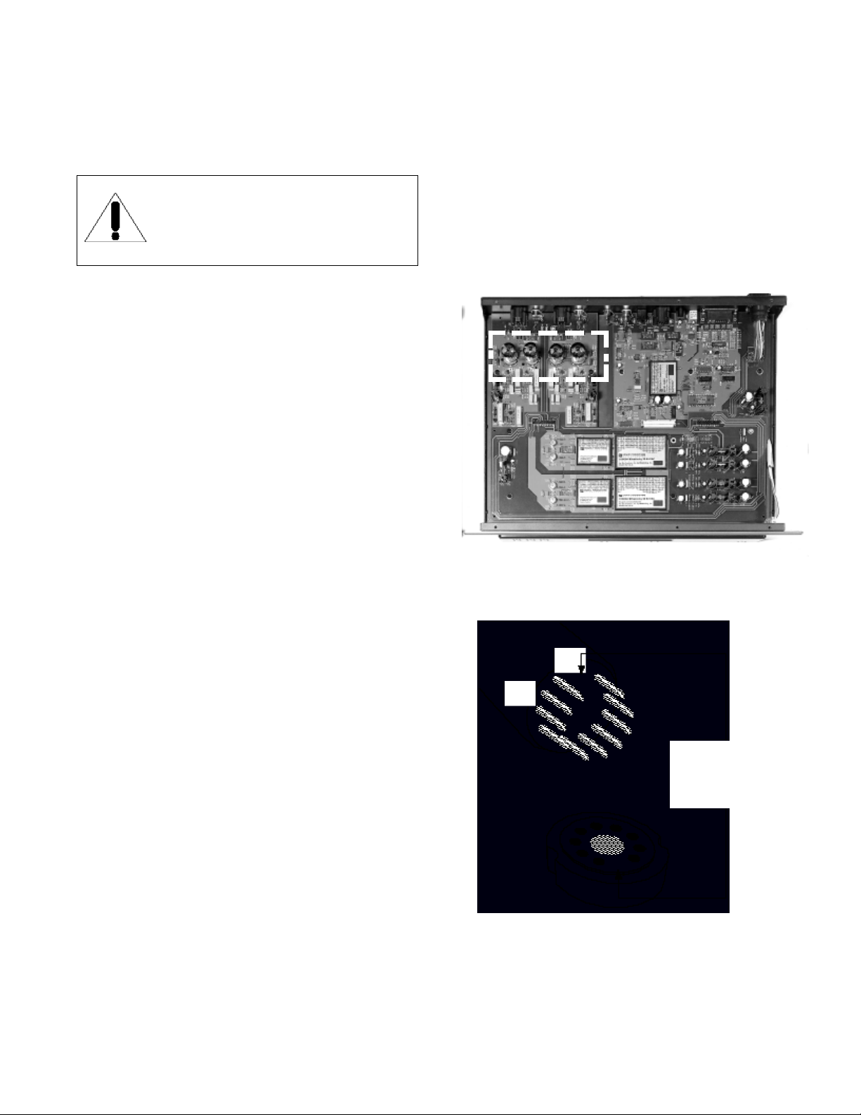
V1
V2 V3
V4
2 . When handling the tubes, it is recommended the cotton gloves
provided be worn to prevent skin oils from depositing on the glass surface. Find the tubes appropriate for your processor, boxed in the
packaging storage compartment.
3 . Inspect the tubes for code markings. They will be labeled
individually, each with one of the following designations: V1 - V4.
4 . Now examine the printed circuit board (PCB) above the tube sockets in the Processor 3 for the designations matching the designations
on the tubes (See Figure 4 for further clarification).
5 . Take the V1 tube and examine the pins noting the large space
between two of the pins. This space will align with the same larger space between two of the pin holes on the socket. Insert the V1
tube into the V1 tube socket, making sure all pins and pin holes
are aligned (see Figure 5). Do not force the tube into the socket.
Rock the tube gently while pushing slowly until the tube is firmly
seated. Repeat this step for the remaining tubes, V2 tube to the V2
tube socket, V3 tube to the V3 tube socket, V4 tube to the V4
tube socket.
Figure 4 - Processor 3 tube installation locations.
Note the larger space
between two of the pins and
holes for proper alignment
of tube and socket.
Figure 5 - Tube pin alignment with the socket.
Page 8
PROCESSOR 3 MAIN AND POWER SUPPLY
CHASSIS PLACEMENT
Under no circumstances should the Processor 3 Power Supply be
placed directly on top of the Processor 3 main chassis, or the
Processor placed on top of the Power Supply. This will not allow
adequate ventilation, and overheating will result. The feet of the
Processor 3 digital processors are temperature sensitive and may
deform if exposed to excessive heat.
The units must be placed on a hard flat surface (N O T on carpet),
preferably side by side or on separate shelves with plenty of
unobstructed space all around the preamp to allow for free movement of air for proper cooling. Do not operate these preamplifiers
in an enclosed cabinet - overheating will result.
Allow at least 6” (15 cm) of clear space all around the Processor
chassis for proper ventilation.
CONNECTING EXTERNAL EQUIPMENT
Up to six digital sources or cables may be connected to the
appropriate input connectors on the rear panel (F,G,H,I,J,K)
using an ST (Glass Fibre) cable, Toslink (Plastic Fibre), BNC
Coaxial cable, RCA Coaxial cable, AES/EBU XLR cable, or
I
2
S•enhanced cable. If a digital recording device such as a
DAT or CD-R is being implemented, an RCA Coaxial cable may
be used for this connection from the Digital Out (L).
Connect the left and right channel balanced XLR audio outputs (if
the existing amplification system is balanced) or the left and right
channel RCA coaxial (single-ended) into the corresponding left and
right channel line level audio inputs of the system’s preamplifier,
control amplifier, integrated amplifier or receiver.
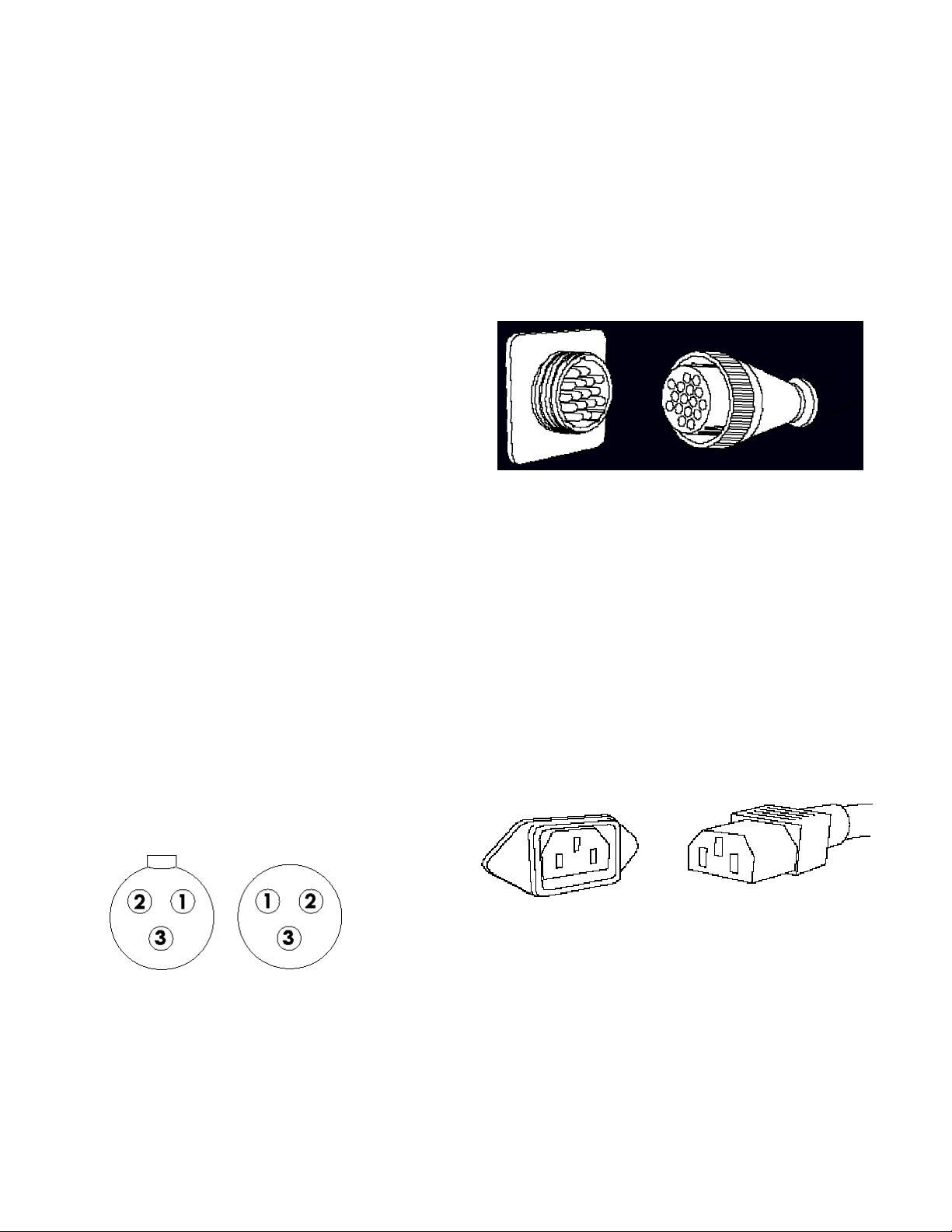
Pin#1- Ground
Pin#2- Positive
Pin#3- Negative
Connector Body - Chassis ground
POWER CONNECTIONS
Once all input and output signal connections are made, you can
begin to make the power connections.
UMBILICAL CORD CONNECTIONS
As the Processor 3 has an external power supply, an additional connection is required. Plug the Power Supply Umbilical cord (T) from the
rear of the Power Supply into the Power Supply Input Socket (E) on
the rear of the processor as shown below in figure 7.
AC POWER CONNECTIONS
Plug the detachable Power Cord into the Power Cord socket (S)
on the back of the Processor 3 power supply. The Processor 3
Digital Processor is configured for the line voltage of the country
in which it is sold. See the shipping box or the rear of the chassis
for voltage settings. If a different operating voltage is required,
please contact an authorized Sonic Frontiers dealer or the factory
directly.
PROCESSOR SET-UP CONT’D
I
N,P
Back Panel View
E
T
Figure 7 - Rotate the connector (Y) on the receptacle (X) until you feel the
notches align to ridges, and then push together. Turn locking ring clockwise until it “clicks” indicating it is locked.
S
Input
(female)
Figure 6
Output
(male)
Figure 8 - Align socket pins to corresponding holes and push together.
Page 9
7
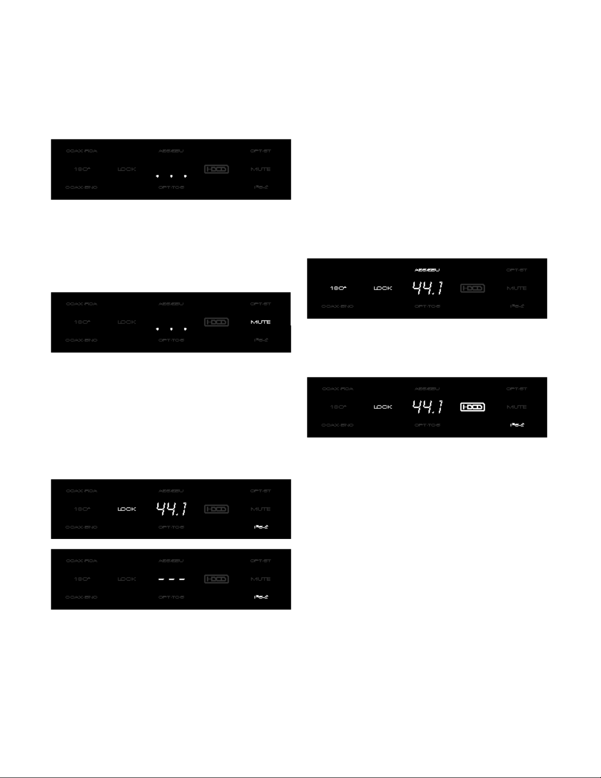
POWERING ON & STARTUP PROCEDURES
1. The Processor 3 power switch located on the front panel of the
power supply should be switched to the ON position. The presence of power will be indicated by a green LED on the front
panel of the power supply, and three dots will light in the center
of the Processor 3’s Display Window, indicating that the
Processor 3 is now in the STANDBY m o d e .
2. With the Processor 3 in the STANDBY mode (as indicated by
the three illuminated dots in the LED display) the STANDBY pushbutton may be depressed, putting the processor into OPERATE
mode. During the warmup interval, before going into OPERATE
mode (approximately 20 seconds), the red MUTE indicator will be
illuminated and the Processor 3’s audio outputs will remain muted.
3. After approximately 20 seconds the processor will be in the
O P E R A T E mode with the default I
2
S • e digital input selected and
indicated in the lower right corner of the display window. The red
LOCK indicator will illuminate and the 3 digit numeric LED readout
will display the clock frequency of the incoming digital audio data,
if present. If digital audio data is not present at the selected digital
input, three horizontal dashes will be displayed and the LOCK L E D
will be extinguished, indicating a NO LOCK condition.
4. If an I
2
S • e capable device is not the source, you may select
the desired digital input using one of the 5 other input buttons (A).
A corresponding indicator will illuminate in the display window
showing your new input selection. If the newly selected source is
on and active, the clock frequency will be displayed and the
LOCK indicator illuminated. When the processor is powered up
and down via the STANDBY button the last input selection will
remain in memory and be recalled. Should the equipment lose
power or be turned off with the main power switch (R), the memory will reset to the initial default state I
2
S • e setting, requiring the
user to reselect the digital input if an I
2
S • e capable device is not
the source.
5. Once a digital input source has been selected you can change
phase polarity from 0°-180° to restore absolute polarity to a
recording which may have been recorded with its polarity inverted.
6. If the incoming data stream has been HDCD encoded, the
H D C D®indicator will illuminate, showing the HDCD decoder is
enabled and processing HDCD audio.
7. The DISPLAY button (C) may be used to set the intensity of the
LED display in the display window to a comfortable viewing level.
Four levels of brightness plus OFF are available by stepping the
DISPLAY button through the range.
8. A three digit numeric display located in the central area of the
display window, indicates the recovered clock frequency of the
incoming data stream selected. One of three frequency values,
32.0, 44.1 or 48.0 kHz* will be displayed automatically corresponding to the clock frequency of the incoming data stream.
*The Processor 3 is designed to be upgradeable to the latest digital audio standards
as they are released. The clock frequencies shown are the values currently available, at
this time, however the display is capable of showing others if they become available,
and the appropriate update pcb’s are installed.
Note: Some digital audio recordings have been produced with
pre-emphasized HF characteristics requiring the digital processor to
recognize and de-emphasize them correctly. The Processor 3
automatically recognizes and performs de-emphasis in the digital
domain via the PMD100 HDCD decoder’s digital filter.
Page 10
If the Processor 3 is not functioning properly, please check each
of the following:
1. Check that the Power Supply Umbilical Cord (T) is connected
correctly to the Power Supply Input Socket (E). Next, ensure that
the AC Detachable Power Cord is plugged into the Power
Supply’s Detachable Power Cord Socket (S) and is connected to
a live source of AC power. For instance, if using a power bar,
check that the bar is turned on.
2. Be sure that the Power Switch (R) on the front of the Processor
3 Power Supply chassis is in the “ON” position.
3. Check that the proper input has been selected with the
Selector Buttons (A) on the Processor 3 chassis.
4. Ensure that the processor is not in MUTE or STANDBY mode,
or still in the 20 second warm-up/turn-on cycle.
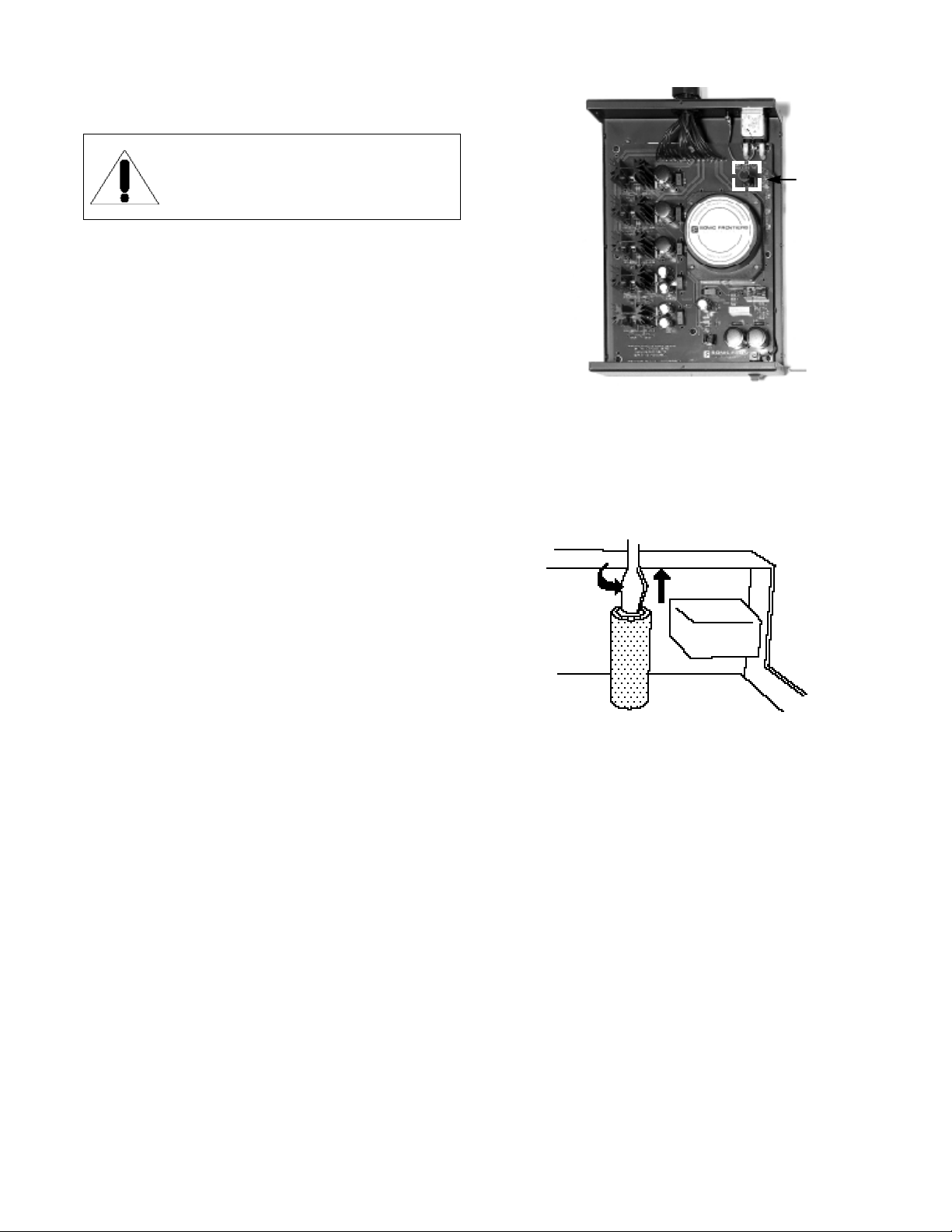
5. Check that the AC Line Fuse inside the Power Supply chassis
is good. Be sure to first unplug the AC Detachable Power Cord
from the Power Supply before removing chassis covers to check
the fuse. For fuse location see figure 9. To remove the fuse, simply unscrew the fuse holder and remove the fuse.
If the fuse has
blown, the thin metal conductor will have melted and the glass may
appear “smoked”. If the fuse has blown, replace with a fuse of the
same type and rating (See specifications for fuse ratings).
6 . Check to be sure that all the tubes are correctly and firmly seated in their tube sockets and that all nine contact pins are inserted
in each socket (i.e. no pins are bent over). Verify that an orange
glow is visible from inside of each tube when the unit is on.
7 . If you are still experiencing any difficulty with your Processor 3,
contact your dealer or distributor for assistance.
REPLACEMENT OF THE TUBES
Sonic Frontiers strongly discourages non-factory replacement of
the tubes. The tubes supplied are measured, selected, and
matched in balanced pairs - channel to channel and triode
section to triode section - for optimum performance.
Problems arising from non-SFI supplied tubes will not be covered
under warranty.
If replacement tubes are needed, desired or required, contact
Sonic Frontiers for assistance.
TROUBLE SHOOTING
Figure 9 - The Fuse in the Processor 3 is located in the right
rear corner of the power supply chassis.
Fuse
W A R N I N G
D I S C O N N E C T the AC Detachable Power Cord
from the Processor 3 Power Supply before
beginning troubleshooting.
Figure 10 - To remove the fuse, simply unscrew the fuse holder
and take out the fuse.
Page 11

SAFETY INSTRUCTIONS
1 . Ventilation - Although your Processor 3 Digital Processor
generates only nominal heat in use, be sure that the ventilation
slots in the top cover have at least 6” of unobstructed air space
above them. Do Not obstruct the bottom vent by operating the
preamplifier on carpet or with the rubber feet removed.
2. Water and Moisture - This product should not be used near
water. Do not expose this product to rain or moisture to prevent
fire or shock hazard.
3 . Heat - This product should be situated away from heat
sources such as radiators, heat registers, stoves, or other appliances which produce heat.
4. Power Sources - This product should be connected to an AC
power source of the proper rated voltage. The original shipping
containers will stipulate the AC voltage this unit can operate with
correctly.
5. Cleaning - A regular dusting with a soft, non-abrasive cloth
will generally keep the finish of the faceplate and chassis looking
like new. At no time should you allow any liquid to come in
contact with the Processor 3 and Power Supply; it may run into
the electronic circuitry and cause damage which will not be covered under your warranty.
6 . Servicing - Do not open this product. No user serviceable
parts inside. Refer servicing to an authorized service technician.
7. Non-Use Periods - The power cord of this product should be
unplugged from the outlet when left unused for an extended
period of time.
8. Do not remove Preamplifier or Power Supply covers while unit
is connected to an AC power source.
PACKING MATERIALS
We recommend that you retain all of the packing material and
shipping boxes for your Processor 3 and Power Supply. They are
custom designed to prevent shipping damage from occurring.
Sonic Frontiers, Inc. will accept no responsibility for any damage
occurring to a Processor 3 and Power Supply that is shipped in
packing material other than the original Sonic Frontiers packing
material.
DISCLAIMER OF LIABILITY
Under no circumstances does Sonic Frontiers, Inc. assume liability or responsibility for injury or damages sustained in the use or
operation of this equipment or for damages to any other equipment connected to it.
Sonic Frontiers, Inc. reserves the right to make design changes or
improvements without the obligation to revise prior versions. All
specifications are subject to change without notice.
LIMITED FIVE YEAR WARRANTY
Sonic Frontiers, Inc. warrants to the purchaser that each
Processor 3 Digital Processor and Power Supply is free of manufacturing defects for a period of five (5) years from the date of
purchase. This five (5) year limited non-transferable warranty
excludes all vacuum tubes, which we warrant for a period of
twelve (12) months. To receive this warranty, the original
purchaser must complete and mail to Sonic Frontiers, within thirty
(30) days from the date of purchase, the enclosed Warranty
Registration Form. Sonic Frontiers, Inc. will then validate the
warranty to the original purchaser. This warranty is subject to the
following conditions and limitations:
1
. Warranty applies only to the original purchaser.
2. This warranty is void and inapplicable if the product has been
handled other than in accordance with the instructions in this
Owner’s Manual, abused or misused, damaged by accident or
neglect or in being transported, or the defect is due to the product being tampered with, modified or repaired by anyone other
than Sonic Frontiers, Inc. or an authorized Sonic Frontiers repair
depot.
3. Warranty does not cover normal maintenance.
4. Sonic Frontiers, Inc. shall not be responsible in any way for
consequential or indirect damages or liabilities resulting from the
use and operation of the product covered herein or resulting from
any breach of this warranty or any implied warranty relating to
said product.
During this period, Sonic Frontiers, Inc. will repair or replace any
defective components free of charge. A Return Authorization
Number (RAN) is required before any product is returned to our
factory for any reason. This number must be visible on the exterior of the shipping container(s) for Sonic Frontiers to accept the
return.
Units shipped to us without a Return Authorization Number or
without a visible RAN on the exterior of the shipping container(s)
will be returned to the sender, freight collect.
Units to be repaired by Sonic Frontiers, Inc. must be sent shipping and insurance prepaid by the original purchaser in the original packing material. A returned product should be accompanied by a written description of the defect. Repaired units will be
returned by Sonic Frontiers, Inc. shipping and insurance prepaid.
All other warranties or conditions either written, verbal, expressed
or implied are void.
Note: In foreign markets (anywhere outside of Canada and the USA),
the warranty is supplied by the authorized International Distributor.
Exact terms and conditions may vary.
9
Page 12
TECHNICAL SPECIFICATIONS
Note: All measurements performed with an Audio Precision System Two test center.
Due to Sonic Frontiers desire to continually improve its products, specifications are
subject to change without notice.
OUT
IN
Optional 0dB
Input Receiver UltraAnalog AES21 AES/EBU
ultra-low jitter Input Receiver
(Note: Not required with I
HDCD®Digital Pacific Microsonics PMD -100
Filter/Decoder
D/A Converters 2 Dual UltraAnalog custom DAC’s
(Balanced Configuration)
2 External custom I to V Modules
Low Pass Analog Filter Proprietary passive filter
Frequency Response 5Hz - 20kHz ± 0.25dB
2
S•e interface)
Fuse Requirements (1) .75 A slow-blo
Power Requirements 60VA
Dimensions: Main - 19” Wide x 14.25” Deep x 4.5” High
(48 cm x 36 cm x 11.5 cm)
Power Supply - 9” Wide x 13” Deep x 4” High
(23cm x 33cm x 10cm)
Net Weight Approx. 30 lbs (14 kg) - unpacked
Warranty 5 years parts and labor
1 year on the tubes
Intrinsic Jitter S/PDIF <30ps (picoseconds)
Jitter Rejection S/PDIF 6dB/octave above 1kHz
Unweighted 20Hz - 20kHz >115dB
S/N Ratio
Crosstalk >130 dB @ 1kHz
THD <0.02%
Maximum Output Level Approx. 6.0 Volts Unbalanced
@ Full Scale Approx. 3.0 Volts Balanced
Output Stage Fully Balanced (for AC and DC parameters),
Digital Inputs (6) S/PDIF - Coaxial (RCA)
2
I
S•enhanced - Below the measurement limits
of commercial test instrumentation
>115 dB @ 16kHz
high speed tube buffer
- Coaxial (BNC)
- ST-Optical (H-P/AT&T)
- Toslink-Optical
AES/EBU - XLR Balanced
2
I
S•e - 13W3 style D-subminiature
connector
A NOTE WITH REGARDS TO HDCD®OPERATION
AND DYNAMIC HEADROOM
The Processor 3 utilizes Pacific Microsonics PMD100 HDCD
decoder technology and is capable of fully decoding and reproducing HDCD encoded material.
The extended dynamic range of the HDCD process requires an
additional 6dB of gain in the Processor 3 output stage, which
has already been incorporated into its design. Although the
majority of recorded material previously available has not been
HDCD encoded, it has been proven beneficial to also increase
the output stage gain 6dB in the Non-HDCD mode taking advantage of the improved analog stage S/N ratio (which results from
the extra output stage headroom).
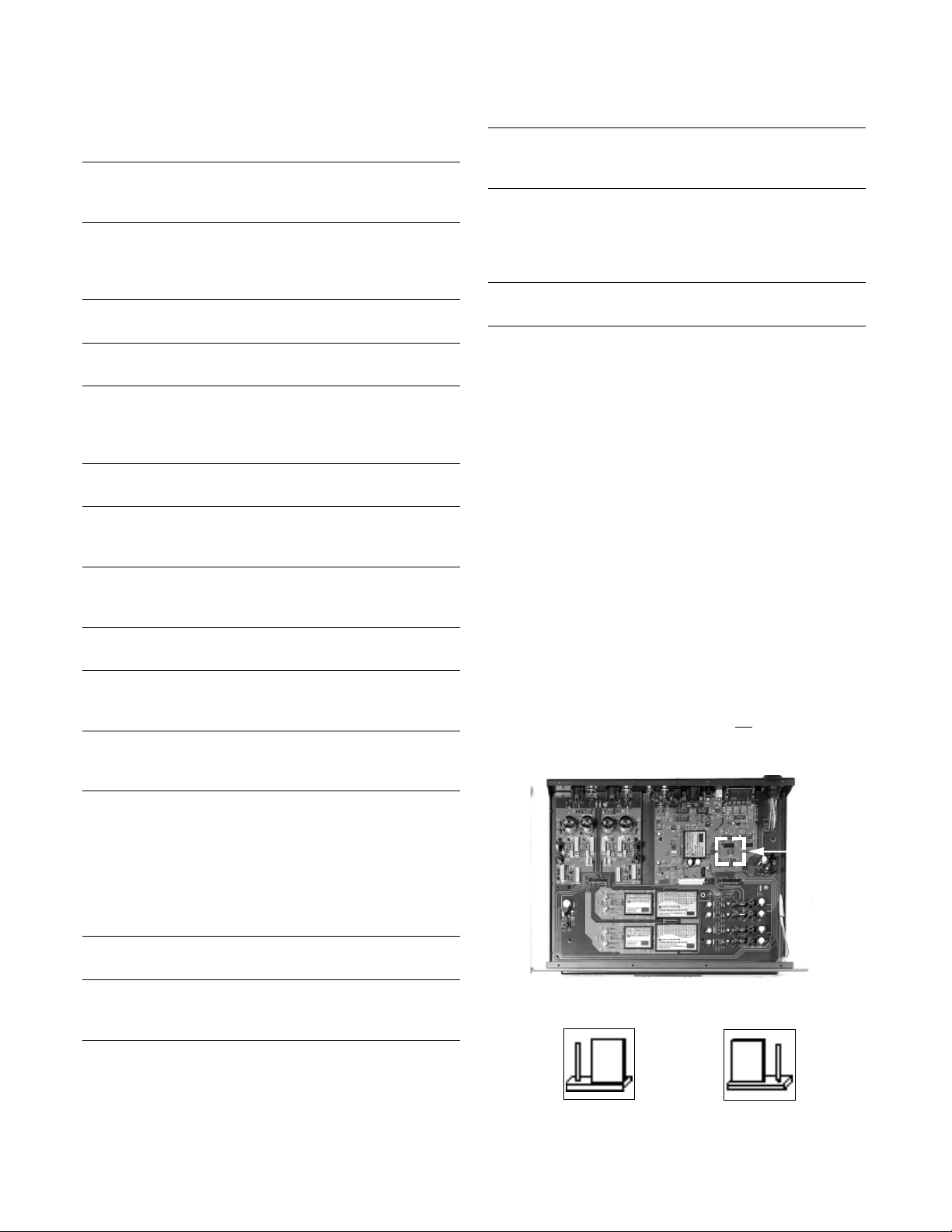
The Processor 3 has been fitted with an internal jumper block
which is factory preset to provide the additional 6dB of gain for
Non-HDCD mode. If additional gain is n o t desired, you may
reset the internal jumper as illustrated in figure 11 & 12.
Jumper
Location
Digital Output (1) S/PDIF - Coaxial RCA
Analog Outputs 1pr. Unbalanced RCA
1pr. Balanced XLR
Tube Complement 4 - 6922 (E88CC)
Figure 11 - Jumper block location.
Figure 12 - Jumper block settings.
OUT
IN
Factory preset +6dB
Page 13

We at Sonic Frontiers are sure that you will derive many years
E - M a i l : S F I @ s o n i c f r o n t i e r s . c o m W e b S i t e : h t t p : / / w w w . s o n i c f r o n t i e r s . c o m
of listening pleasure with your new Processor 3 Digital Processor.
This Operating Manual contains important information regarding
the operation and care of the Processor 3. Be sure to read this
manual carefully and follow these instructions in order to keep it
looking, operating and sounding its best.
Sonic Frontiers can be reached from 9:00 a.m. to 5:00 p.m., Eastern Standard Time, or 24 hours a day by facsimile.
2790 Brighton Road, Oakville, Ontario, Canada, L6H 5T4 Telephone: (905) 829-3838 Facsimile: (905) 829-3033
 Loading...