


OWNER’ S MANUAL
THE SONIC FRONTI ERS SFL - 2 PREAMPL IFIER AND POWER SUPPLY

K |
|
L |
|
M |
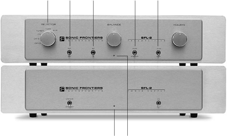
OPERATION, CONNECTIONS AND CONTROL FUNCTIONS
A - Power Input Socket - Plug the Preamplifier Power Cord (M) from the Power Supply into this socket. Simply align the plug and socket so the plug inserts easily and freely when pushing the connection together. Screw on locking ring allowing it to “click” to secure the connection (see Figure 1).
B - Sets 1 & 2 of the XLR Balanced Outputs - These outputs are balanced and should be used when connecting outputs to another balanced unit. These two outputs allow for easier biamping and greater flexibility when dealing with components such as electronic
c r o s s o v e r s , etc. As with all outputs and inputs on this Preamplifier the left channel is situated on the upper row of connectors and the right channel is on the lower row.
C - Sets 1 & 2 of the RCA Single-Ended Outputs - These unbalanced outputs are single ended and should be used when connecting the outputs to another single-ended unit. These two outputs, as with the XLR outputs (B), allow for easier biamping and greater system flexibility.
D - RCA Single-Ended Tape Output - These outputs connect to the inputs of a tape deck. When not recording these outputs should be muted via the Record/Off Switch (O).
E - RCA Single-Ended Auxiliary Input - This input will accept a single-ended input connection from a high-level source such as a
V C R or a step-up device for a moving coil or moving magnet phono cartridge such as our SFP-1or SFP-1 Signature Phono Stage.
F - RCA Single-Ended Tape Input - This input accepts a singleended input connection from a tape source.
G - RCA Single-Ended Tuner Input - This input accepts a singleended input connection from a tuner source.
H - RCA Single-Ended Compact Disc Input - This input accepts a single-ended input connection from a compact disc player or a digital -to-analog processor such as our SFD-1 or SFD-2.
I - Direct RCA Single-Ended Input - This input accepts a singleended input connection from any source to achieve the highest possible sonic performance, bypassing the Balance Control (Q) and the Record/Off Switch (O).
J - Direct XLR Balanced Input - This input accepts a balanced input connection from any source to achieve the highest possible sonic performance, bypassing the Balance Control (Q) and the Record/Off Switch (O).
K - Detachable Power Cord Socket - Plug the Power Supply’s Detachable Power Cord into this socket (see Figure 2). The SFL-2 is factory set for the correct operating voltage for the area in which it is sold (see shipping box for voltage setting). If a different operating voltage is required, please contact an authorized Sonic Frontiers dealer, distributor or the factory directly.
L - AC Line Fuses - These are the left and right channel AC fuses. They may be accessed with a small slot screwdriver by turning a 1/2 turn counterclockwise to unlock a spring that ejects the fuse holders out. The unit is factory installed with “fast-blo” 1.5 Amp 250V (0.25” x 1.25”) or 0.75 Amp 250V (0.25” x 1.25”) for European
and Asian versions.
M-Power Supply Umbilical Cord - This Umbilical Cord exits the Power Supply to plug into the Power Input Socket (A) on the SFL-2 Preamplifier (see Figure 1 for connection). It does not disconnect from the Power Supply.
U |
|
V |
|
W |
|
X |
N -Selector Switch - This knob is turned to select an input (E) through (J). O -Record/Off Switch - This toggle switch turns the outputs off and prevents the main preamp outputs from being loaded down by the
non-linear load of most tape decks when the record functions are not in use. To record, move the switch to the record position and wait a short delay (5 seconds) for the protective muting function to clear and connect the tape outputs.
P - 180°/0° Switch - This toggle switch allows the user to invert the system phasing easily and safely. Depending upon the methods used in producing the recording, the user may prefer listening to a given recording in either phase position - let your ears be your guide.
Q -Balance Control - This knob controls the relative balance of the left and right channels to compensate for any discrepancies caused by speaker placement, source imbalance, etc.
R - Mute/Operate Switch - In the mute position, this toggle switch cuts off the signal to the SFL-2 outputs (Band C); the LED (W) flashes as a reminder. In the operate mode, the outputs are connected.
S - -1.5 dB/0 dB Switch - This toggle allows for greater volume control over the 23-step/3 dB per step Volume Attenuator (T). In the -1.5 dB position the volume level will be reduced by 1.5 dB. This feature provides the attenuator with a total of 46 discrete steps, allowing the user a wide, precise volume control range.
T - 23-Step Precision Balanced Volume Attenuator Control - This knob controls the balanced attenuator. The attenuator is manufactured with a ladder of precision metal film resistors that give precise control over left and right channel levels in 3 dB steps over 23 positions. Turn it clockwise and the music gets louder!
U - Operate/Standby Switch - When this toggle switch is in the operate position and the Power Supply Switch (X) is on, the Preamplifier is fully functional. In the standby “resting” mode, power is still supplied to the tube filaments, but the high voltage power supplies are disconnected from the audio circuitry.
V - LED Power Supply - This LED lights when the Power Supply is on. W-LED Preamplifier - This LED lights when the Preamplifier is on
and flashes during warmup, muting, or low voltage from the A.C. power source.
X - On/Off Switch - In the “on” position, this toggle turns the Power Supply on. In the “off” position, the Power Supply and Preamplifier are off.
Note: Be sure the Power Supply Umbilical Cord (M) that is attached to the Power Supply chassis is plugged into the Preamplifier chassis before the On/Off Switch (X) is turned on. Failure to do this may cause damage to the SFL-2.
 Loading...