


OWNER’ S MANUAL
THE SONIC FRONTIERS SFD - 2 MKII DIGITAL PROCESSOR
CONTROL FUNCTIONS AND CONNECTIONS
A |
|
B |
|
C |
|
D |
|
E |
|
F |
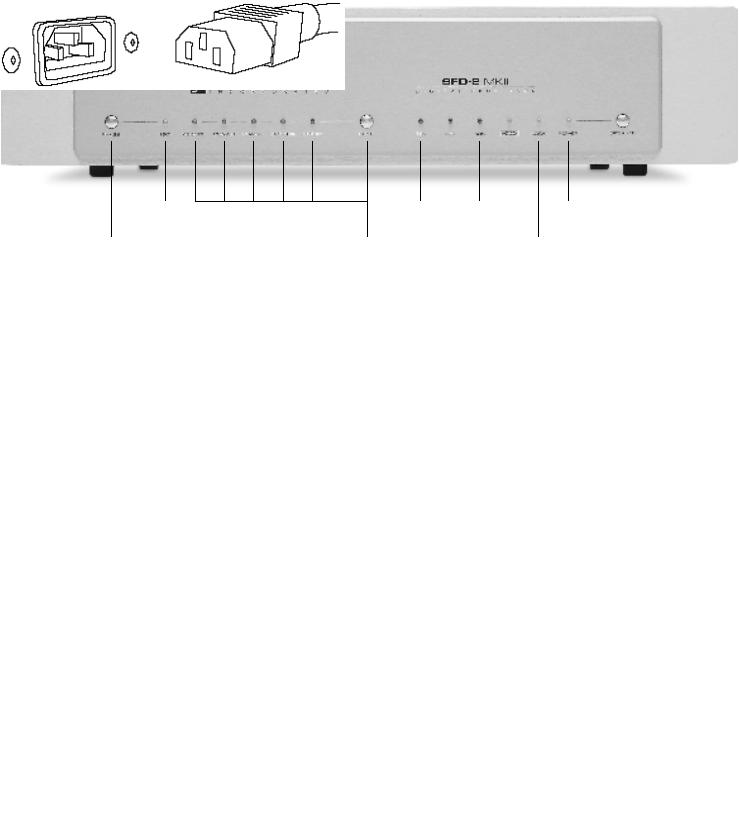
A-Phase Control Switch & LED - This switch allows the user to invert the system phasing easily and safely. The switch is set automatically to the 0° position where the SFD-2 MKII will put out a normal or non-inverted signal in relation to the signal being received from the source. Pushing the switch will put out an inverted version of the signal as compared to that being received from the source. The LED will light indicating that the source signal phase is being inverted 180°. This feature offers a convenient method of correcting source material which was recorded “out of absolute phase” or to compensate for a component in your system, such as a preamplifier, power amplifier or signal connection, which inverts phase.
B -Input Switch & Indicator LEDs - This switch selects between the 5 digital inputs (I-M) located on the back of the SFD-2 MKII: AES/EBU XLR, Coax RCA, Coax BNC, Optical Toslink, Optical Standard (Glass Fibre). A connection to all 5 inputs may be made from 5 separate sources. To switch digital sources, depress the button repeatedly to scan the inputs. The LED will light corresponding to the input selection.
C -Sampling Frequency Indicator LEDs - One of these LEDs will light, indicating the frequency of the digital input signal. The sampling frequencies are 32K, 44K and 48K.
D-H D C D® LED - This will light when an HDCD (High Definition Compatible Digital) encoded digital track is being played. The HDCD decoding is switched in automatically by the SFD--2 MKII circuitry, and no user adjustments are necessary.
E - Signal Locking Indicator LED - This LED will light when an operational digital source is selected.
NOTE: Depending on the source or transport being used in conjunction with the SFD-2 MKII, it may be necessary to have the source unit in the “P L A Y” mode and the SFD-2 MKII receiving the digital transmission before the LED will light.
F - Operate Switch & Power LED - This switch, when pressed, allows the SFD-2 MKII to receive full power, rendering the SFD-2 MKII operational as indicated by the Power Indicator LED. When the switch is off, the Power LED will not be lighted and the SFD-2 MKII is not receiving full power; under these conditions the SFD-2 MKII is not operational, but is in standby m o d e .
Figure 1 - Align socket pins to corresponding holes and push together firmly.

L O
G |
|
H |
|
I |
|
J |
|
K |
|
M |
N |
G -Detachable Power Cord Socket - Plug the Detachable Power Cord into this socket (see Figure 1). The SFD-2 MKII is factory set for the correct operating voltage for the area in which it is sold (see shipping box for voltage setting). If a different operating voltage is required, please contact an authorized Sonic Frontiers dealer, distributor or the factory directly.
H -Digital Out - This output jack provides a digital signal for dubbing purposes with a Digital Audio Tape (DAT) or Compact Disc recorder (CD-R).
I - H-P/ST (Glass Fibre) Optical Input - This input will accept a digital connection from a digital source’s Glass Fibre Optical digital output. This connection type is considered best for optimum performance and sound quality; if your source unit has this type of digital output, we recommend its use.
J - Toslink (Plastic Fibre) Optical Input - This input will accept a digital connection from a digital source’s Toslink (Plastic Fibre) Optical digital output.
K -Coaxial BNC Cable Input - This input will accept a digital connection from a digital source’s BNC - Coaxial digital output. The BNC - Coaxial cable impedance should be 75 ohms.
L - Coaxial RCA Cable Input - This input will accept a digital connection from a digital source’s RCA - S/PDIF - Coaxial digital output. The RCA - S/PDIF - Coaxial cable impedance should be 75 ohms.
M-AES/EBU XLR Input - This input will accept a digital signal from a digital source’s AES/EBU XLR digital output. A 110 ohm balanced cable terminated with XLR plugs should be used for this connection.
NOTE: The XLR jack pin connectors for the SFD-2 MKII are configured as follows: Pin #1 : Ground
Pin #2 : Positive (+) Phase
Pin #3 : Negative (–) Phase
N- Left and Right Channel Balanced XLR Audio Output Connectors - These are balanced audio outputs and should be used when connecting the SFD-2 MKII to the balanced audio inputs of a line level preamplifier, control amplifier, integrated amplifier or receiver, if these units are so equipped (see Figure 4). (Left channel output of the SFD-2 MKII connects to the left channel input of control unit and right channel output of the SFD-2 MKII to the right channel input of control unit.)
NOTE: The XLR jack pin connectors for the SFD-2 MKII are configured as follows: Pin #1 : Ground
Pin #2 : Positive (+) Phase
Pin #3 : Negative (–) Phase
O-Left and Right Channel RCA Single-Ended Audio Output Connectors - If the balanced inputs are not applicable for use, the RCA single-ended (unbalanced) audio outputs should be used when connecting the SFD-2 MKII to the RCA single-ended audio inputs of a line level preamplifier, control amplifier, integrated amplifier or receiver. (Left channel output of the SFD-2 MKII connects to the left channel input of control unit and right channel output of the SFD-2 MKII to the right channel input of control unit.)
 Loading...