


close |
open |
|
twist 350
Installation and Operating Instructions 1 - 38
Serial number
twist-350-46800V001-112013-0-OCE-Rev._GB

Table of contents
General Information....................................................... |
3 |
Symbols............................................................................................ |
3 |
Safety instructions............................................................................ |
3 |
Intended use..................................................................................... |
3 |
Improper use..................................................................................... |
4 |
Combined operation......................................................................... |
4 |
Permitted gate wing dimensions....................................................... |
4 |
Technical data................................................................................... |
4 |
Dimensions....................................................................................... |
4 |
Functional description....................................................................... |
4 |
Installation preparations............................................... |
6 |
Scope of supply................................................................................ |
6 |
Safety instructions............................................................................ |
6 |
Tools required................................................................................... |
6 |
Personal safety equipment............................................................... |
6 |
Installation...................................................................... |
7 |
Tips for installation............................................................................ |
7 |
Drive installation position.................................................................. |
7 |
A/B dimension table (reference value).............................................. |
8 |
Installation of fittings......................................................................... |
8 |
Post or pillar fitting............................................................................ |
8 |
Gate wing fitting................................................................................ |
9 |
Installing the control unit.................................................................. |
11 |
Connection to power mains (AC 230 V).......................................... |
11 |
Connect the drive to the control unit............................................... |
12 |
Opening gate outwards................................................................... |
13 |
Setting the end positions................................................................ |
14 |
Instructions for setting the end positions........................................ |
15 |
Initial operation............................................................ |
15 |
General information........................................................................ |
16 |
Preparations for continuous operation............................................ |
16 |
Adjusting the gate wing length........................................................ |
16 |
Performing the learning run and activating continuous operation... |
16 |
Checking the direction of running................................................... |
16 |
Initial operation............................................................ |
16 |
Learn the drive (run the learning procedure at least twice)............ |
17 |
Control unit reset............................................................................ |
17 |
Initial operation............................................................ |
17 |
Programming the hand-held remote control................................... |
18 |
Safety instructions.......................................................................... |
18 |
Normal mode.................................................................................. |
18 |
Obstacle detection.......................................................................... |
18 |
Summer-winter mode..................................................................... |
18 |
Intermediate stop............................................................................ |
18 |
Operation / Use............................................................. |
18 |
Opening and closing gate............................................................... |
19 |
Emergency release in case of power failure................................... |
19 |
Display and button explanation....................................................... |
20 |
Programming the hand-held remote control................................... |
20 |
Deleting a hand-held remote control button from the radio receiver20 |
|
Deleting all radio codes of a channel.............................................. |
20 |
Functions and connections........................................ |
20 |
Deleting the radio receiver memory................................................ |
21 |
External antenna............................................................................. |
21 |
Troubleshooting.............................................................................. |
21 |
Functions and connections........................................ |
21 |
Safety instructions.......................................................................... |
22 |
Jumper............................................................................................ |
22 |
Button on control unit...................................................................... |
22 |
Potentiometer for gate wing length................................................. |
22 |
Radio connector.............................................................................. |
22 |
TorMinal interface........................................................................... |
22 |
Light-emitting diodes (LED)............................................................ |
23 |
DIP switches................................................................................... |
24 |
Automatic closing function.............................................................. |
24 |
Fuses.............................................................................................. |
26 |
Connection to power mains (AC 230 V)............................................ |
26 |
Transformer terminal....................................................................... |
27 |
Connect electric lock 1.................................................................... |
28 |
Connecting warning light................................................................ |
28 |
Functions and connections........................................ |
28 |
Connecting drives........................................................................... |
29 |
Connecting button........................................................................... |
29 |
Key switch....................................................................................... |
30 |
Connecting button (gate OPEN)..................................................... |
30 |
Connecting button (gate STOP)..................................................... |
30 |
Connecting button ("Gate CLOSE")................................................ |
30 |
Connecting EMERGENCY STOP................................................... |
30 |
Connect a two-wire photo eye........................................................ |
31 |
Connecting safety device................................................................ |
31 |
Connecting external consumers..................................................... |
31 |
Potential-free relay contact............................................................. |
31 |
Functions and connections........................................ |
31 |
Maintenance and care.................................................. |
32 |
Safety instructions.......................................................................... |
32 |
Regular testing................................................................................ |
32 |
Miscellaneous............................................................... |
33 |
Disassembly................................................................................... |
33 |
Disposal.......................................................................................... |
33 |
Troubleshooting........................................................... |
34 |
Tips on troubleshooting.................................................................. |
34 |
Connection diagram.................................................... |
36 |
DIP switches................................................................. |
37 |
DIP switch and TorMinal settings of DTA-1 control unit ................. |
37 |
Wiring diagram............................................................. |
38 |
– 2
General Information
Symbols
Attention symbol:
Important safety instructions!
To ensure personal safety, it is important to observe all instructions. Save these instructions!
Note symbol:
Information, useful advice!
Refers to a respective picture in the introduction or main text.
Safety instructions
General
¾¾ These installation and operating instructions must be read, understood and complied with by persons who install, use or perform maintenance on the drive.
¾¾ The manufacturer does not accept liability for damage or interruptions to business resulting from non-observance of the installation and operating manual.
¾¾ Always ensure compliance with accident prevention regulations and current standards in each respective country.
¾¾ All applicable Directives and standards must be observed for installation and operation, such as: EN 12453, EN 12604, EN 12605.
¾¾ Follow and comply with the "ASR A1.7 Technical Regulations for
Workplaces" of the committee for workplaces (ASTA). (Applies to operators in Germany).
¾¾ Before working on the gate or the drive, always disconnect the plant and lock to prevent reactivation.
¾¾ All electrical wires must be fitted tightly and secured against shifting.
¾¾ There is a risk of persons being crushed or cut by the mechanism or sharp edges of the gate.
¾¾ Never operate a damaged drive.
¾¾ After installation and commissioning, all users must be instructed in the function and operation of the swing gate drive.
¾¾ Only use OEM (Original Equipment Manufacturer) spare parts, accessories, and mounting material.
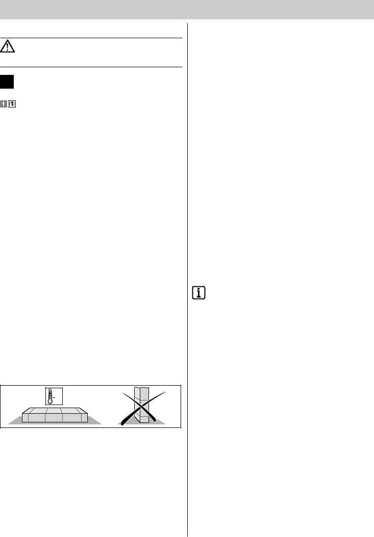
Storage
¾¾ The drive must be stored in an enclosed, dry area at a room temperature between -20 and +70 °C.
¾¾ The drive should be stored horizontally.
+70°
20°
Operation
¾¾ Do not allow children or persons who have not been instructed to operate the gate control unit.
¾¾ Open and close the gate only if there are no children, persons, animals, or objects within its range of motion.
¾¾ Actuate the gate system by remote control only if you have a clear view of the gate.
¾¾ Never put your hand near the gate when it is moving or near moving parts.
¾¾ Regularly check the safety and protection functions and repair faults when they are detected. see Care and maintenance.
¾¾ Drive through the gate only when it has opened completely.
¾¾ Set the force tolerance as low as possible.
¾¾ For automatic closing the main and auxiliary closing edges must be secured in accordance with the applicable directives and standards.
¾¾ Always remove the key to ensure that unauthorized persons cannot unlock the drive and open the gates.
Radio remote control
¾¾ The remote control must only be used for devices and systems in which radio interference will not endanger people, animals or objects or the risk is reduced by other safety devices.
¾¾ The user must be made aware that systems that pose an accident risk should only be remote controlled, if at all, if the user can actually see the gate.
¾¾ The radio remote control may only be used if the gate’s movement can be watched and no persons or objects are within the range of movement.
¾¾ Store the hand-held transmitter so that unintended operation, e.g., by children or animals, is impossible.
¾¾ The operator of the radio system is not protected from faults due to other telecommunications equipment or devices (e.g. radio-controlled systems that are licensed to operate in the same frequency range).
If substantial interference occurs, please contact your appropriate telecommunications office which has radio interference measuring equipment (radiolocation).
¾¾ Do not operate the hand-held transmitter in areas with sensitive radio communications or systems (e.g. airports, hospitals).
Type plate
¾¾ The type plate is inside the cover of the control unit.
Intended use
Note!
After installation of the drive the person responsible for the installation must complete an EC declaration of conformity for the gate system in accordance with
the Machinery Directive 2006/42/EC and apply the CE mark and a type plate. This is also required for private installations and also if the drive is retrofitted to a manually operated gate. This documentation and the Installation and Operating Instructions are retained by the operator.
¾¾ The drive is intended exclusively to open and close gates. Any other use does not constitute intended use. The manufacturer accepts no liability resulting from use other than intended use. The user bears the sole responsibility for any risk involved. The warranty expires as a result.
¾¾ Gates automated with a drive must comply with all valid standards and directives: e.g. EN 12453, EN 12604, and EN 12605.
¾¾ The safety distances between the gate wing and the environment can be found in standard EN 12604.
¾¾ The drive must be in good technical condition, and it must be used for its intended purpose with awareness of the hazards as described by the installation and operating manual.
¾¾ Faults that may affect safety must be repaired without delay. ¾¾ The gate must have very little play in the hinges.
¾¾ The gates must be stable and resistant to twisting, i.e. they must not bend or twist when opening and closing.
¾¾ The DTA-1 control unit and the twist 350 drive must only be used together.
¾¾ The DTA-1 control unit and the twist 350 drives are designed for private use.
¾¾ The electric drive is designed exclusively for opening and closing one or two-wing swing gate installations.
– 3
General Information
Improper use
¾¾ Opening or closing flaps, e.g. for access to roofs or similar.
Combined operation
¾¾ Mixed operation with 1 x twist 200 E/EL and 1 x twist 350 is permitted only in combination with the twist XS #3248V000 (five-wire technology) conversion kit on the twist XL (DTA-1) control unit.
¾¾ Mixed operation with 1 x twist 350 and 1 x twist XL is permitted only in combination with the twist XL (DTA-1) control unit.
Permitted gate wing dimensions
Weight: |
|
Max. 300 kg |
|
|
|
|
|
|
|
|
|
|
|
|
|
|
|
Gate inclination: |
0% |
|
|
|
|
|
||
Height (m) |
|
|
|
Degree of fill (%) |
|
|
|
|
|
|
|
|
|
|
|||
|
|
|
|
|
|
|
|
|
3 |
100 |
|
100 |
100 |
90 |
60 |
45 |
|
|
|
|
|
|
|
|
|
|
2.5 |
100 |
|
100 |
100 |
100 |
75 |
55 |
|
|
|
|
|
|
|
|
|
|
2 |
100 |
|
100 |
100 |
100 |
90 |
68 |
|
1.5 |
100 |
|
100 |
100 |
100 |
100 |
90 |
|
|
|
|
|
|
|
|
|
|
1 |
100 |
|
100 |
100 |
100 |
100 |
100 |
|
0.5 |
100 |
|
100 |
100 |
100 |
100 |
100 |
|
|
|
|
|
|
|
|
|
|
Length (m) |
1.2 |
|
1.5 |
2 |
2.5 |
3 |
3.5 |
|
|
|
|
|
|
|
|
|
|
* Valid with B-dimension 300 mm + A-dimension 100 mm.
Technical data
|
1-wing |
2-wing |
Unit |
||
General |
|
|
|
|
|
Runtime depending on |
Approx. |
|
Approx. |
|
Seconds |
A/B size |
12 …25 |
|
15 …34 |
|
|
Protection type |
|
|
|
|
|
Operator |
IP 44 |
|
IP 44 |
|
|
|
|
|
|
|
|
Control unit housing |
IP 65 |
|
IP 65 |
|
|
|
|
|
|
||
Rated voltage |
220 - 240 |
220 - 240 |
AC/V |
||
Rated frequency |
50/60 |
|
50/60 |
|
Hz |
|
|
|
|
|
|
Operating temperature range |
|
|
|
|
|
Operator |
-30 |
+70 |
-30 |
+70 |
°C |
|
|
||||
|
|
|
|
|
|
Control unit housing |
-30 |
+70 |
-30 |
+70 |
°C |
|
|
||||
Lift (per drive) |
450 |
|
450 |
|
mm |
|
|
|
|
|
|
Max. tension and compress. |
2500 |
|
2500 |
|
N |
force |
|
|
|
|
|
Duty cycle: |
40 |
|
40 |
|
% |
Stand by |
|
|
|
|
|
Rated current consumption |
33.6 |
|
33.6 |
|
mA |
|
|
|
|
|
|
Rated wattage |
2.2 |
|
2.2 |
|
W |
|
|
|
|
|
|
Rating |
|
|
|
|
|
Motor voltage: |
Approx. 22 |
Approx. 20 |
DC/V |
||
Rated current consumption: |
Approx. 1.7 |
Approx. 3 |
A |
||
|
|
|
|
||
Rated power consumption: |
Approx. 400 |
Approx. 680 |
W |
||
Workplace-related emission value < 75 dBA – drive only.
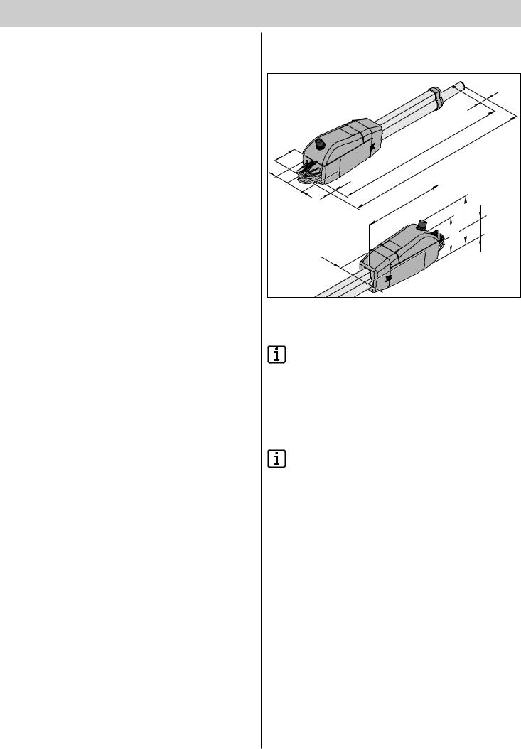
Dimensions
All dimensions are in millimeters.
|
|
|
|
|
17 |
|
|
|
|
.1450 |
|
|
|
|
|
-Cmax |
.1490 |
|
||
65 |
.955 |
-max |
|
|
||
|
Cmin |
. |
|
|
|
|
|
|
995 |
|
|
|
|
58 |
|
min |
|
|
|
|
25 |
|
|
|
|
|
|
58 |
|
|
|
|
|
|
|
315 |
|
|
|
180 |
|
|
|
|
|
158 |
56 |
|
|
6 |
|
|
|
|
|
|
11 |
|
|
|
|
|
Functional description
Note!
The end positions ("Gate OPEN" + "Gate CLOSE") are set by internal limit switches in the drive and detected during operation.
The gate wing is opened and closed by retracting and extending the gate operator. When the defined end positions are reached, the drive is automatically switched off by the limit switch.
Closing the gate
Note!
A mechanical end stop is essential when the gate operator is fully extended. An electric lock can be installed as an additional lock.
The gate wing does not require a lock, because the drive is self-locking. The gate cannot be pushed open manually without damaging the drive or the fittings.
Wireless actuation
The drive can be actuated with the included hand-held transmitter once the transmitter has been set to the radio receiver.
Safety devices
The control system has an automatic force monitor. If the drive requires more force for opening or closing than the value saved during the learning run, the drive stops and reverses ("Gate CLOSE" direction) or remains stationary ("Gate OPEN" direction).
Various safety devices can be connected to the control unit (see additional functions and connections).
E.g.
•Photo eye.
•Safety contact strip with additional evaluation unit.
– 4

General Information
Declaration of Installation
for the installation of an incomplete machine
in accordance with the Machinery Directive 2006/42/EC, Appendix II, Section 1 B
SOMMER Antriebsund Funktechnik GmbH Hans - Böckler - Straße 21 - 27
73230 Kirchheim unter Teck Germany
hereby declares that the control unit
twist 350
as of the identifi cation, twist 350 complies with the Machinery Directive 2006/42/EC and is intended for installation in a gate system.
•The following fundamental safety requirements have been applied and observed in accordance with Appendix I:
-General principles No. 1
-1.2 Safety and reliability of control units
Safety input I terminals 17 + 18: Cat 2 / PL C
Internal force limitation Cat 2 / PL C
Safety categories in accordance with EN 13849 - 1:2008
•Compliant with the regulations of the EC Building Products Directive 89/106/EC.
For the operating forces part, the respective initial testing has been carried out in consultation with recognized inspecting authorities. In doing so, the harmonized standards EN 13241-1, EN 12453 and EN 12445 have been applied. For the tested combinations, refer to the "Reference list" table in the Internet under www.sommer.eu.
•Compliant with the Low Voltage Directive 2006/95/EC.
•Compliant with the Directive on Electromagnetic Compatibility 2004/1 08/EC.
•The technical documentation was drawn up in accordance with Appendix VII B.
The product may only be put into operation after it has been established that the door system complies with the regulations of the Machinery Directive.
i.V.
Kirchheim, 25-02-2013
Jochen Lude
Responsible for documents
– 5
Installation preparations
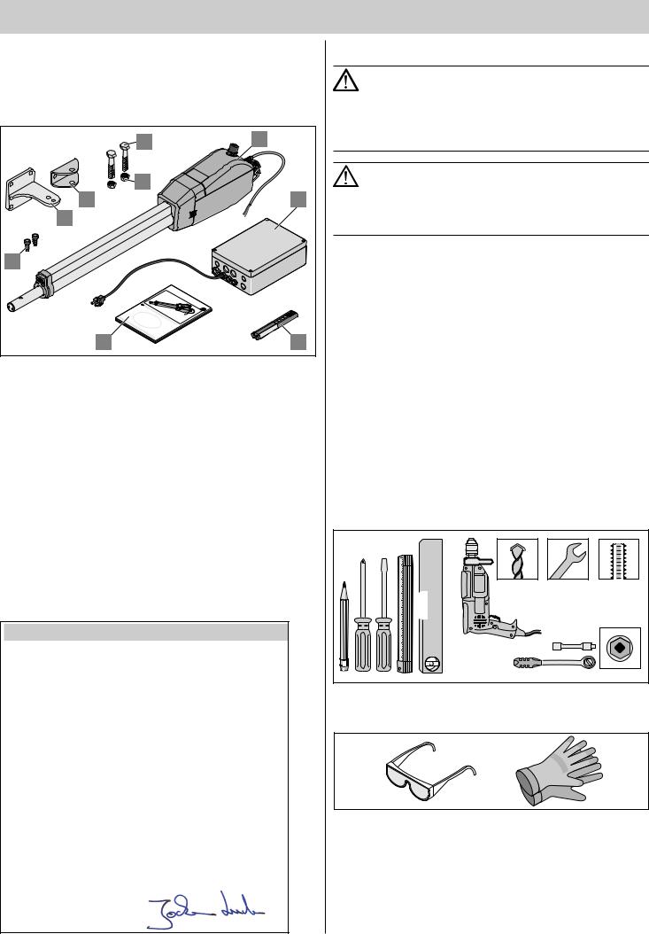
Scope of supply
¾¾ Check the package before installation to avoid unnecessary work and expense if a part is missing.
¾¾ The actual scope of supply may vary depending on the design of the drive.
|
7 |
2 |
|
8 |
|
|
5 |
3 |
|
6 |
|
9 |
|
|
close |
open |
|
|
|
|
|
twist350 |
|
|
D |
|
|
1 |
4 |
Complete set |
1-wing |
2-wing |
|
|
Weight |
14 |
22 |
kg |
|
|
|
|
|
|
Package (L x W x H): |
1190 x 246 x 203 |
mm |
||
1. |
Installation and Operating |
1 x |
1 x |
|
Instructions |
|
|
|
|
2. |
Drive with cable |
1 x |
2 x |
|
|
|
|
|
|
3. |
Control unit in housing (including |
1 x |
1 x |
|
radio receiver, transformer, and |
|
|
|
|
power plug) |
|
|
|
|
4. |
Hand-held transmitter, including |
1 x |
1 x |
|
battery |
|
|
|
|
5. |
Fittings for gate wing |
1 x |
2 x |
|
|
|
|
|
|
6. |
Fittings for post or pillar |
1 x |
2 x |
|
|
|
|
|
|
7. |
Stainless steel hex bolt M10x45 |
2 x |
4 x |
|
|
|
|
|
|
8. |
Stainless steel locknut M10 |
2 x |
4 x |
|
|
|
|
|
|
9. |
Plug |
2 x |
4 x |
|
|
|
|
|
|
D Funkempfänger
EU-Konformitätserklärung
Safety instructions
Note!
The control unit is delivered with a mains cable. This cable may be used only for the mounting of the drives.
After the conclusion of mounting, the mains cable must be disconnected and replaced by a permanently laid line. The mains cable is not approved for constant or outdoor operation.
Note! Danger of destruction by voltage fluctuations.
Voltage fluctuations, e.g. from welding machine, can destroy the control unit.
Do not connect the control unit until all mounting tasks on the power mains has been concluded.
¾¾ Install all wiring for the drive in ducts approved for the purpose (e.g. for underground installation).
¾¾ The control unit must be connected to the power supply by an electrician only.
¾¾ Installation must be in accordance with the installation and operating manual.
¾¾ Remove or disable locking devices (electric locks, bars etc.) before installing the drive.
¾¾ Ensure that the drive is securely fastened to posts, pillars, and gate wings to withstand forces generated when opening and closing
the gate.
¾¾ Cover or remove the drive when welding fittings to posts, pillars, or gate wings to prevent damage from sparks.
¾¾ If a button is used for opening or closing, it must be installed at a height of at least 1.6 m to prevent operation by children.
¾¾ Use only approved fasteners (e.g. wall plugs or anchor pins 12 x 100) in public areas.
Tools required
 Mit SOMMER sind Sie immer gut ausger ichtet!
 8 mm 2x 17 mm M 10 8 mm
Die Firma
SOMMER Antriebsund Funktechnik GmbH Hans-Böckler-Straße 21-27
D-73230 Kirchheim/Teck
erklärt, daß das nachfolgend bezeichnete Produkt bei bestimmungsgemäßer Verwendung den grundlegenden Anforderungen gemäß Artikel 3 der R&TTE-Richtlinie 1999/5/EG entspricht und daß die folgenden Normen angewandt wurden:
Produkt: |
RF Remote Control for Doors & Gates |
Typ: RM01-868, RM02-868-2, RM02-868-2-TIGA RM03-868-4, RM04-868-2, RM08-868-2 RM01-434, RM02-434-2, RM03-434-4, RM04-434-2
RX04-RM02-868-2, RX04-RM02-868-2-TT
RX04-RM02-434-2, RX04-RM02-434-2-TT
Angewandte Richtlinien und Normen sind:
-ETSI EN 300220-2:2007-06
-ETSI EN 301489-1:2008-04
-DIN EN 60950-1:2006
Kirchheim/Teck, 21.06.2010
Jochen Lude
Dokumentenverantwortlicher
17 mm
Personal safety equipment
¾¾ Safety glasses (for drilling). ¾¾ Work gloves.
– 6
|
Installation |
|
|
8 |
|
|
1 2 x 0,75 mm2 |
|
|
|
5 |
|
|
|
2 |
|
|
|
4 x 0,75 mm2 |
|
3 |
6 |
|
|
|
||
|
|
|
3 x 1,5 mm2 |
|
|
|
AC 230V |
|
|
|
4 x |
|
|
|
5 x 1,5 mm |
|
close |
open |
|
|
|
|
|
3
2 x 0,75 mm2
2 x 0,75 mm2
4 |
7 |
|
5 x 1,5 mm |
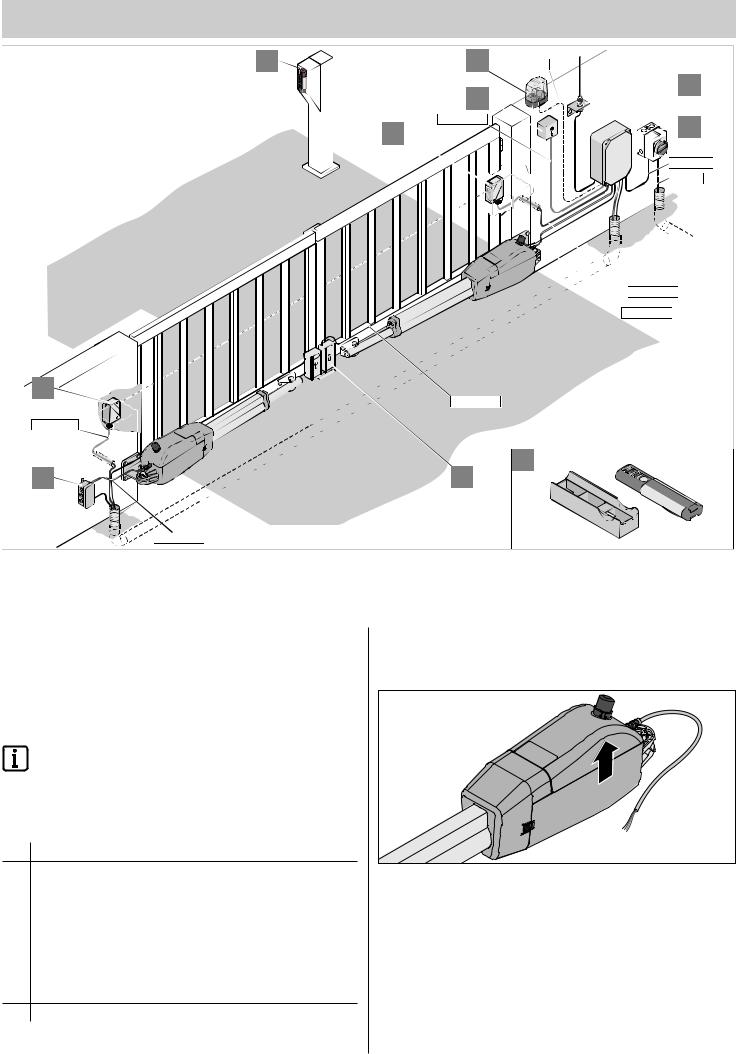
Tips for installation
•Define the installation location together with the operator.
•Do not install the housing where it could be seen from the street, otherwise the housing and control unit may be damaged by vandalism.
•If the gate wings are larger than 3 m or there are two wings, attach a threshold or a threshold bar to the gate.
Note!
Additional pulse transmitters are: hand-held transmitters, Telecody, wireless indoor switches and key switches.
In the case of the hand-held transmitter, Telecody or
the wireless indoor switches a connecting line to the drive is not required (contact your dealer).
1.Warning light DC 24 V/25 W.
2. |
Key switch (1 or 2 contact). |
3. |
Photo eye. |
|
|
4. |
Connector wiring set 7 m. |
5. |
Main switch (lockable). |
6. |
Rod antenna (including cable). |
|
|
7. |
DC 24 V electric lock—an electric lock can be mounted separately |
|
on each gate wing. |
8. |
Telecody. |
9.Car/wall holder for hand-held transmitter.
Drive installation position
Install drive horizontally. Note installation position of motor; it must always point upright.
– 7
Installation
A/B dimension table (reference value)
Note!
Before mounting, define the A/B dimensions. Without these dimensions, the drive cannot be correctly installed and operated.
•Note different post or pillar dimensions.
|
A |
100 |
120 |
140 |
160 |
180 |
200 |
W |
D |
|
|
|
|
|
|
120 |
90º |
96º |
96º |
110º |
110º |
110º |
|
140 |
92º |
99º |
102º |
105º |
111º |
117º |
|
160 |
91º |
94º |
100º |
100º |
106º |
111º |
|
180 |
91º |
94º |
99º |
100º |
100º |
106º |
|
200 |
91º |
93º |
97º |
98º |
100º |
102º |
|
220 |
91º |
93º |
97º |
98º |
100º |
98º |
|
240 |
91º |
93º |
97º |
98º |
100º |
93º |
|
260 |
91º |
93º |
96º |
98º |
93º |
|
|
280 |
91º |
93º |
94º |
|
|
|
|
300 |
91º |
92º |
|
|
|
|
|
320 |
91º |
|
|
|
|
|
|
Note!
The reference values in the table have been calculated based on the following data:
●Gate wing height 2 m
●Gate wing length 3.5 m
●Wind load 32.6 m/s
●Max. permissible axial force < 20 KN
Installation of fittings
Note!
The strength of the included fittings is designed for the drive (twist 350). If other fittings are used, the warranty will not apply.
Note!
If the B dimension is smaller than the smallest B dimension in the table, install a spacer plate under the post fitting
to ensure that the B dimension is at least 120 mm (see A/B dimension table).
¾¾ Cover or remove the drive when welding fittings to posts, pillars, or gate wings to prevent damage from sparks or welding beads.
¾¾ With thick brick or concrete pillars attach the fittings so the wall plugs cannot come loose during operation. Adhesive-bonded anchors,
with which a threaded pin is cemented to the brickwork without tension, are more suitable than steel and plastic expanding plugs.
Note!
Only use permissible fastening materials.
¾¾ Clearances between the gate wing and post or gate wing and drive must be maintained in accordance with the applicable standards.
Steel posts
Note the thickness of the post!
The fitting can be welded or bolted directly to steel posts.
Brick or concrete pillars
When attaching the fitting to the brick pillar, ensure that the holes are not too close to the edge of the pillar. The distance may vary depending on the type of plug. The plug manufacturer will provide recommended distances.
Note!
Select A/B dimensions in such a way that the desired opening angle is reached. The specified opening angle (D) is reference value for the largest possible angle.
In case of gate wings greater than 3 m, the B dimension must amount to at least 160 mm.
220 |
|
240 |
260 |
|
121º |
|
110º |
92º |
|
121º |
|
110º |
92º |
|
109º |
|
106º |
92º |
|
107º |
|
101º |
92º |
|
100º |
|
95º |
92º |
|
95º |
|
91º |
|
|
90º |
• |
Dimensions A, B in mm. |
||
|
||||
|
• |
D = largest possible opening angle in degrees. |
||
|
• |
1 revolution = 1.25 mm adjustment path when |
||
|
|
adjusting the limit switch. |
||
Note!
After mounting the fittings, do not perform any more welding or grinding. Residues of such work will result in rapid corrosion of fittings.
Post or pillar fitting
|
|
|
|
100 |
130 |
115 |
95 |
10 |
78 |
|
||||
|
|
|||
|
|
|
|
|
25 |
8 |
78 |
100 |
|
|
|||
50 |
10,5 |
|
|
|
|
|
|
|
– 8
Installation
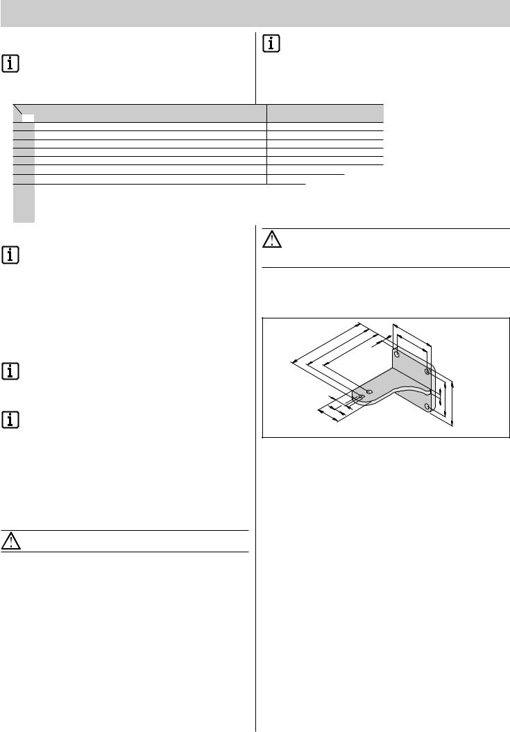
Gate wing fitting
|
70 |
30 |
40 |
|
50 |
|
|
|
|
|
|
|
|
10 |
|
8,5 |
18,5 |
10 |
|
|
|
||
37 |
3 |
|
|
Note!
Fix post and pillar fittings into place accordingly using a clamp before permanent mounting and then check
the installation situation and installation dimensions. Even if everything is correct, the fitting must be permanently mounted.
To achieve the greatest possible stability, the C1 dimension should be as small as possible.
For this reason. the dimensions should amount to C1min = 60 mm.
A |
|
|
B |
|
= |
|
|
|
|
|
C1max |
|
|
m |
|
|
555m |
C |
x |
= 1450mm |
|
ma |
|
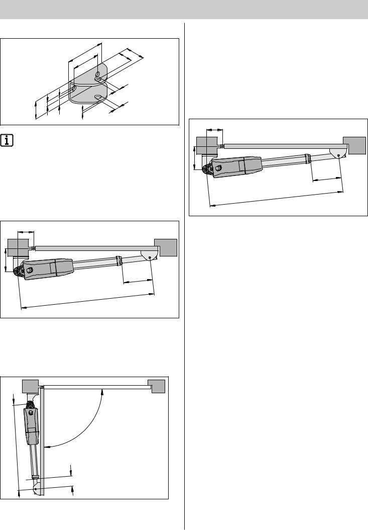
1.Close the gate manually.
2.Measure the A and B dimensions and compare them with the A/B dimension table.
3.Mount the post fitting onto post in accordance with the selected A/B dimensions.
Fastening height of at least 50 mm from the ground
D |
|
mm |
|
955 |
|
= |
|
n |
|
mi |
|
C |
|
C1min |
= 60mm |
|
|
4.Bring the gate into position that will later be the "Gate OPEN" position.
In the process, note the maximum possible opening angle D from
the A/B dimension table.
5.Remove the drive from the packaging, hang it in the post fitting, and secure it with a screw.
The drive is at maximum retraction as delivered.
Unscrew the gate operator by one turn.
6.Fix the gate wing fitting to the gate operator of the drive.
Insert the screw from above.
7.Fasten the drive temporarily to the gate with the gate fitting (e.g. with a clamp).
8.Close the gate manually.
Unlock the drive to do so (see "Unlocking the drive").
A |
|
|
B |
|
= |
|
|
|
|
|
C1max |
|
|
m |
|
|
555m |
C |
x |
= 1450mm |
|
ma |
|
9.Measure the C1 dimension on the drive and make sure that the C1max dimension does not amount to more than 555 mm.
10.Check whether the drive is horizontal in the following positions:
-"Gate OPEN"
-"Gate CLOSE"
-Opened by 45°
11.Check the position of the fittings.
Fix the fittings to the gate when it is correctly positioned.
12.Screw in the nuts of the connecting screws (drive to fittin) only tight enough that the drive can still be turned easily.
– 9

Installation
5
4
3
1
2
|
|
|
|
|
|
|
6 |
|
|
|
|
|
|
11 |
|
|
|
|
|
|
|
|
|
|
|
|
|
|
|
|
|
|
|
|
|
|
|
|
|
|
7 |
|
|
|
|
|
|
12 |
|
|
|
|
|
|
|
|
|
|
|
|
|
|
|
|
8 |
|
|
|
|
Start |
|
|
|
|
|
|
|
|
|
|
|
t |
2 |
|
|
|
10 |
|
|
|
|
S |
ow |
1 |
|
|
|
|
|
9 |
|
|
e |
|
|||
|
|
|
|
|
|
|
|
|
|
||
|
|
|
|
|
|
|
|
|
|
Star |
|
|
|
|
|
|
|
|
|
|
|
|
|
41 |
42 |
|
|
0 |
39 |
4 |
|
S
US |
|
E |
|
2 |
|
5x |
0 |
|
|
s
27t |
25 |
23 |
21 |
19 17 
13 11
9 7 5 

|
|
4 |
|
17 |
|
|
18 |
|||
|
3 |
|
|
|
|
|
|
|
||
|
|
|
|
|
|
|
|
|
|
|
1 |
2 |
|
|
|
|
|
|
|
|
|
|
|
|
|
|
|
|
|
|
|
|
|
|
|
PE |
|
|
|
|
|
|
|
|
PE |
|
|
|
|
16 |
|
|
||
|
15 |
|
|
|
|
|
||||
|
|
|
|
|
|
|
||||
|
|
|
|
|
|
|
|
|||
|
|
|
|
|
|
|
|
|
|
|
19
21
20
13
14
2
3
4 
1. |
Slot for four-channel radio receiver. |
11. |
Secondary transformer. |
2. |
DIP switches. |
12. |
Primary transformer. |
3. |
Button (Start 1). |
13. |
Fuse 1.6 A, slow-acting. |
4. |
Button (Start 2). |
14. |
Mains connection. |
5. |
Connection of the external antenna. |
15. |
Connecting strip for accessories. |
6. |
LED (Start 1, Start 2, Power, Safety). |
16. |
Connecting strip for motor 2. |
7. |
Potentiometer (Gate 2) for force tolerance of Motor 2. |
17. |
Connecting strip for motor 1. |
8. |
Potentiometer (Gate 1) for gate wing length of Motor 1. |
18. |
Connecting strip for button. |
9. |
Potentiometer (Time) for automatic closing function. |
19. |
LEDs (limit switches). |
10. |
TorMinal interface. |
20. |
Connecting strip for safety accessories. |
|
|
21. |
Potential-free relay contact. |
|
|
|
|
– 10
Installation
Installing the control unit
Note!
The control unit is supplied with a mains cable for use in installing the drives only. On completion of installation disconnect the mains cable and replace it with permanent wiring. The mains cable is not approved for continuous or outdoor operation.
Note! |
|
|
|
Implement the mains connection according to EN 12453 |
|||
(all-pole line disconnector). |
|
||
|
|
160 |
mm |
|
175 |
|
|
mm |
mm |
|
|
|
|
||
|
|
|
|
75 |
|
|
|
250mm |
|
|
235mm |
4x |
|
|
|
|
|
|
6x M16 |
|
|
|
3x M20 |
ATTENTION: Danger of destruction by water
Penetration of water may destroy the control unit.
Use the fixture points provided for screwing on the housing.
Do not drill through the rear wall of the housing. The housing is not sealed, water will penetrate and the control unit will be destroyed.
¾¾ Disconnect the power to the control unit before working on it. ¾¾ Dry any moisture that enters the housing with a fan.
¾¾ The control unit must be connected to the power supply by an electrician only.
¾¾ Install the control unit housing in a perpendicular position with the wire feed at the bottom without strain to prevent penetration of water and the cover is watertight.
¾¾ The wire feeds are approved only for wires 1.5 mm² to 2.5 mm² in cross section.
¾¾ Use the fixture points provided for screwing on the housing. Do not drill through the rear wall of the housing. Otherwise, the housing is leaky.
Connection to power mains (AC 230 V)
Note!
The control unit must be connected to the power mains by an electrician.
Note!
Approved wire cross sections for all terminals: 0.5 mm² - 2.5 mm².
Note!
Insert the sheeth of the connecting line into the control unit housing.
Do not remove the sheath of the mains supply line until it is in the control unit housing!
Note!
Remove the sheath as shown in the graphic!
L + N |
PE |
25mm 50mm max. min.
|
5 |
|
8 |
|
|
|
1 |
|
|
|
16 |
5x20 |
|
|
14 |
|
|
12 |
|
|
|
10 |
|
|
|
|
|
|
|
|
8 |
|
|
4 |
6 |
|
3 |
|
|
|
|
|
|
|
2 |
|
|
|
1 |
|
|
Terminal |
Description |
Description |
|
1 |
L |
Mains supply line AC 230 V. |
|
|
|
2 |
N |
Neutral wire. |
|
|
|
3 + 4 |
PE |
Protective earthing conductor. |
Note!
Secure the line with a cable binder against being moved!
– 11

Installation
Connect the drive to the control unit. Gate 2 wing
ATTENTION
Connect the drives only with the control unit disconnected from the mains voltage and locked to prevent reactivation. The control unit recognises the connected drives only under these circumstances.
Note!
Never connect the drive directly to the AC 230 V. This will destroy the motor immediately.
Note!
Note the jumper setting!
Gate 1 wing
T
AN
|
|
St |
|
|
|
|
a |
|
|
St |
|
rt |
|
|
|
2 |
|
||
|
a |
|
2 |
|
|
|
rt |
|
|
w |
|
1 |
t |
|
|
Star |
|||
|
|
|
||
e |
|
|
|
|
|
r |
|
|
|
|
|
|
1 |
|
|
|
|
t |
D |
|
|
|
Star |
|
|
|
|
|
|
|
5 |
ON |
4 |
3 |
|
|
2 |
|
1 |
Ti |
e |
|
2
9
|
15 |
17 |
|
|
|
11 |
13 |
|
|
|
|
|
1 |
2 |
|
|
|
|
|
12 |
8 |
10 |
|
|
|
|
6 |
|
|
M2
21 |
23 |
|
|
19 |
|
5 |
26 |
4 |
24 |
3 |
22 |
|
20 |
16 |
|
14 |
|
Terminal |
Contact |
Function |
11 |
1 |
Motor |
13 |
2 |
Motor |
15 |
3 |
"Gate CLOSE" |
|
|
limit switch |
17 |
4 |
"Gate OPEN" |
|
|
limit switch |
19 |
5 |
Earth limit |
|
|
switch |
Description
1 wing: Connection for the motor.
2 wing: Connection for motor
2. The motor must be on the gate wing that opens first or rather, which has no external stop bar.
M1 |
2. |
1. |
M2 |
T |
|
|
|
AN |
|
|
|
|
|
St |
|
|
|
|
a |
|
|
St |
|
rt |
|
|
|
2 |
2 |
||
|
art |
|
||
w |
|
1 |
t |
|
|
Star |
|||
|
|
|
||
e |
|
|
|
|
|
r |
|
|
|
1 |
|
|
t |
|
D |
Star |
|
|
|
|
|
|
|
5 |
ON |
4 |
|
3 |
||
|
1 |
2 |
|
|
|
Ti |
e |
|
|
|
|
2
3 |
15 |
|
10
17 |
|
|
14 |
16 |
|
|
||
12 |
2 |
|
1 |
||
|
20 18 
4 3
1 M
|
|
|
|
21 |
|
|
|
17 |
19 |
|
|
15 |
|
|
|
|
|
|
|
22 |
11 |
13 |
|
5 |
|
|
4 |
||
|
9 |
|
2 |
3 |
|
|
1 |
|
|
|
|
|
18 |
|
5 |
|
|
|
|
|
|
|
16 |
|
|
|
|
|
|
|
|
|
|
2 |
|
|
|
12 |
M |
|
|
|
|
|
|
8 |
10 |
|
17 |
|
|
|
||
|
|
|
1 |
|
|
6 |
|
|
Terminal |
Contact |
Function |
Description |
|
12 |
1 |
Motor |
2 wing: Connection |
|
14 |
2 |
Motor |
for motor 1. The motor |
|
must be on the gate |
||||
16 |
3 |
"Gate CLOSE" limit |
||
wing that opens |
||||
|
|
switch |
second or, rather, |
|
18 |
4 |
"Gate OPEN" limit |
that has an external |
|
stop bar. |
||||
|
|
switch |
||
|
|
|
||
20 |
5 |
Earth limit switch |
|
|
11 |
1 |
Motor |
1 wing: Connection for |
|
|
|
|
the motor. |
|
13 |
2 |
Motor |
2 wing: Connection |
|
15 |
3 |
"Gate CLOSE" limit |
for motor 2. The motor |
|
|
|
switch. |
must be on the gate |
|
|
|
wing that opens first or |
||
17 |
4 |
"Gate OPEN" limit |
||
rather, which has no |
||||
|
|
switch |
external stop bar. |
|
19 |
5 |
Earth limit switch. |
|
1.Connecting drive to control unit.
▫▫ First connect and adjust the drive for the gate with stop (M1) and then the drive for the walk-through gate (M2).
S |
e |
S |
|
|
|
|
r |
|
|
|
|
|
|
|
ty |
1 |
|
|
P |
|
|
|
Start |
|
DI |
8 |
|
|
|
|
|
7 |
||
|
|
|
|
|
|
|
G |
|
|
|
5 |
6 |
|
|
|
4 |
|
|
||
|
|
|
|
|
||
a |
|
ON |
3 |
|
|
|
2 |
|
|
|
|
||
|
1 |
2 |
|
|
|
|
G |
|
|
|
|
|
|
|
|
|
|
|
|
|
a |
|
|
|
|
|
|
2. Set all DIP switches to “OFF”.
|
St |
|
|
|
|
|
|
Sta |
|
|
|
|
|
|
|
St rt |
a |
|
|
|
|
|
St |
|
|
|
|
|
|
|
rt2 |
|
|
|
|
rt2 |
|
2 |
|
|
||||
P |
|
|
|
|
2 |
|
|
P w |
|
|
|
|
|
|
|
|
|
|
|
|
|
|
|
|
|
|
|
||
o |
|
|
|
|
|
|
o |
|
|
Start |
|
|
||
|
w |
|
|
Start |
|
|
|
|
|
|
|
|||
|
|
|
|
|
|
|
|
|
|
|
|
|
||
ty |
|
|
1 |
|
|
|
P |
ty |
|
1 |
|
|
P |
|
|
t |
Start |
|
|
DI |
|
t |
Start |
|
|
DI |
|||
|
|
|
|
8 |
|
|
|
|
8 |
|||||
|
|
|
|
|
|
|
7 |
|
|
|
|
|
|
7 |
|
|
|
|
|
|
5 |
6 |
|
|
|
|
|
5 |
6 |
|
|
|
ON |
4 |
|
|
|
ON |
4 |
|
||||
|
|
|
|
|
|
|
|
|
||||||
|
|
|
3 |
|
|
|
|
3 |
|
|
||||
|
|
|
|
1 |
2 |
|
|
|
|
|
1 |
2 |
|
|
|
|
|
|
|
|
|
|
|
|
|
|
|
||
|
|
|
|
e |
|
|
|
|
|
|
e |
|
|
|
|
|
|
m |
|
|
|
|
|
m |
|
|
|
||
|
|
|
Ti |
|
|
|
|
|
|
Ti |
|
|
|
|
|
2 |
|
|
|
|
|
IC4 |
2 |
|
|
|
|
|
4 |
|
|
|
|
|
|
|
|
|
|
|
|
|
||
|
1 |
|
|
|
|
|
|
1 |
|
|
|
|
IC |
|
|
G |
|
|
|
|
|
|
G |
|
|
|
|
|
|
3.Set jumpers: 1 or 2-wing gate system.
4.Connect control unit to the power supply.
"POWER" LED lights, "Status" LED flashes, and all other LEDs are off.
– 12
 Loading...