


ASB-6010A |
|
|
ASB-5014A |
Attach guarantee |
|
sticker here! |
||
Original installation and operating manual |
|
1 - 43 |
|
|
|
ASB6010A-46786V001-222012-0-OCE-Rev._GB

Copyrights and proprietary rights
The manufacturer retains the copyright for this manual. No part of these instructions may be reproduced in any form without the written permission of SOMMER Antriebsund Funktechnik GmbH or processed, copied,
or distributed using electronic systems.
Violations of the specifications above will lead to damage claims.
All brands mentioned in these instructions are the property of their respective manufacturer and hereby recognized as such.
Contact data
If you need customer service, spare parts, or accessories, please contact your specialist dealer or SOMMER Antriebsund Funktechnik GmbH directly.
SOMMER Antriebsund Funktechnik GmbH Hans-Böckler-Str. 21-27
D-73230 Kirchheim/Teck www.sommer-torantriebe.de info@sommer.eu
0049 / 7021 / 8001-400
Feedback regarding this manual
We have tried to make the Installation and Operating Instructions as easy as possible to follow. If you have any suggestions as to how we could improve them or if you think more information is needed, please send your suggestions to us:
0049 / 7021 / 8001-403
doku@sommer.eu
Information regarding the barrier
Serial No.: |
Specified on the title page of this manual. |
Year of |
From 2012 |
manufacture: |
|
Information regarding the manual
Version of the manual |
Rev. |
The language of the original installation and operating manual is German.
All other language versions are translations of the original installation and operating manual and thus labeled as such.
– 2

Table of contents
User information............................................................ |
4 |
Storage and circulation of the manual.............................................. |
4 |
Description of the product type......................................................... |
4 |
Target group of the manual............................................................... |
4 |
Other applicable documents............................................................. |
4 |
Explanation of symbols..................................................................... |
4 |
Information regarding the depiction of text....................................... |
4 |
Safety instructions......................................................... |
5 |
Warranty........................................................................................... |
5 |
Intended use..................................................................................... |
5 |
Improper use..................................................................................... |
5 |
Qualification of the personnel........................................................... |
5 |
Operator responsibilities................................................................... |
6 |
Safety labeling on the barrier............................................................ |
6 |
Personal safety equipment............................................................... |
6 |
Spare parts and accessories............................................................ |
6 |
Product description....................................................... |
7 |
Scope of supply................................................................................ |
7 |
Dimensions....................................................................................... |
8 |
Technical data................................................................................... |
8 |
Type plate......................................................................................... |
8 |
Transport/unloading/storage........................................ |
9 |
Transport........................................................................................... |
9 |
Unloading and in-house transport..................................................... |
9 |
Storage............................................................................................. |
9 |
Installation preparations............................................. |
10 |
Installation drawing.......................................................................... |
11 |
Creation of barrier foundation with supply connections................... |
11 |
Creating the foundation of the support post..................................... |
11 |
Stationary command initiators........................................................ |
12 |
Safety measures............................................................................. |
12 |
Pedestrian traffic............................................................................. |
12 |
Tools required................................................................................. |
12 |
Installation.................................................................... |
13 |
Safety information for installation.................................................... |
13 |
Check the scope of supply.............................................................. |
13 |
Installation of the barrier housing.................................................... |
13 |
Adapting the length of the boom..................................................... |
14 |
Installation of the boom................................................................... |
14 |
Installation of a LED boom.............................................................. |
14 |
Installation of the support post........................................................ |
14 |
Aligning the position of the barrier.................................................. |
15 |
Installation of accessories............................................................... |
15 |
Connection to the power mains...................................................... |
17 |
Initial operation............................................................ |
18 |
Safety information for installation.................................................... |
18 |
Check of the cable of the direct connector..................................... |
18 |
Adjustment of the spring unit.......................................................... |
18 |
Checking the direction of running................................................... |
18 |
Check of the path of the barrier...................................................... |
19 |
Performing a control system reset and relearning the force values.20 |
|
Adjusting the force tolerance.......................................................... |
20 |
Optional hand-held transmitter................................... |
21 |
Safety information for the remote control........................................ |
21 |
Deleting the radio receiver memory................................................ |
21 |
Programming the hand-held remote control................................... |
21 |
Deleting the hand-held transmitter from the radio receiver............. |
21 |
Deleting a channel from the radio receiver..................................... |
21 |
Loss of a hand-held transmitter...................................................... |
21 |
Operation and control.................................................. |
22 |
Safety information on operation...................................................... |
22 |
Operation with automatic closing function...................................... |
22 |
Single channel operation................................................................ |
23 |
Emergency release......................................................................... |
23 |
Control.......................................................................... |
24 |
Safety instructions.......................................................................... |
24 |
Overview of the control system....................................................... |
24 |
Mains connection............................................................................ |
25 |
Functions of the control system...................................................... |
25 |
DIP switches................................................................................... |
26 |
Regular testing and maintenance............................... |
27 |
Troubleshooting........................................................... |
28 |
Change the fuse............................................................................. |
28 |
Changing the spring........................................................................ |
28 |
Changing lights............................................................................... |
29 |
Troubleshooting........................................................... |
29 |
Troubleshooting........................................................... |
30 |
Fault - cause - elimination............................................................... |
30 |
Disassembly and disposal.......................................... |
32 |
Safety information for disassembly................................................. |
32 |
Storage after disassembly.............................................................. |
32 |
Description of the disassembly work.............................................. |
32 |
Disposal.......................................................................................... |
33 |
EC Declaration of Conformity......................................................... |
34 |
Entrance and exit scenarios........................................................... |
35 |
Drill template................................................................................... |
39 |
Barrier handover report................................................................... |
41 |
Brief instructions............................................................................. |
43 |
– 3
User information
Storage and circulation of the manual
This manual must always be available at the site of installation and use of the barrier.
The operator must inform the personnel about the storage location of this manual and its supplementary manuals.
If the manual has become unreadable due to constant use, the operator must obtain a replacement from the manufacturer. To reorder the manual, contact the Customer Service department.
During the transfer or resale of the barrier to third parties, the following document must be passed on to the new owner:
•This manual
•The retrofitting and repair work documents
•Proof of regular testing
•Other applicable documents; see the "User Information - Other Applicable Documents" chapter.
Description of the product type
The ASB-6010A / ASB-5014A barrier has been constructed according to state-of-the-art technology and recognized technical regulations and is subject to the EC Machinery Directive (2006/42/EC). A Declaration of
Conformity has been included in this manual.
This manual describes an industrially, commercially, and privately usable, powered barrier for vehicle traffic. The barrier is used to block and open entrances and exits from parking lots and other drives.
The ASB-6010A / ASB-5014A barrier is available in both right-closing and left-closing designs. A conversion is not possible.
Optionally available accessories are also described. The actual scope of supply may deviate.
Target group of the manual
The manual must be read and observed by everyone assigned with one of the following tasks:
•In-house transport
•Unpacking and installation
•Commissioning
•Adjustment
•Troubleshooting
•Testing
•Decommissioning
•Disassembly
•Storage
•Disposal
Other applicable documents
In addition to this manual, observe the following (technical) documents/ regulations:
•National regulations regarding accident prevention
•National regulations regarding environmental protection
•Information regarding supervisory and reporting responsibilities, as well as company organization
•Recognized technical regulations for safe work
Explanation of symbols
The following symbols and signal words are used in this manual:
Danger
Designates an immediate danger that leads to death or extremely severe injuries.
Warning
Designate a possibly dangerous situation lead can lead to death, extremely severe injuries, or damage to the barrier and environment.
Note:
Designates more information and useful tips.
Refers to a part or machine component in a picture.
Warning symbols
If the source of danger can be specified more precisely, the following symbols are used together with the abovementioned signal words:
Danger due to electric current!
In case of contact with live parts, current can flow through a body, possibly leading to electric shock, burns, or death.
Danger of tipping!
This symbol is used to label a danger of tipping during the transport and installation of the barrier.
Danger due to closing barrier!
The non-observance of the rules of behavior lead to a dangerous situation that can lead to severe injuries.
Information regarding the depiction of text
¾ Stands for general safety instructions that must be observed!
Stands for directions for an action with one or two instructions. 1. Stands for directions for an action with three or more instructions.
•Stands for lists of the action.
Stands for the results of the action.
Lists without a mandatory order are shown as a list with bullets (Level 1) and en-dashes (Level 2):
•List 1
––Point A
––Point B
•List 2
References to chapters and other documents are bolded, italicized, and placed in "quotation marks."
– 4

Safety instructions
Warranty
The warranty complies with statutory requirements. The contact person for warranties is the dealer.
The warranty is only valid in the country in which the barrier was purchased.
Batteries, fuses and lights are excluded from the warranty.
Intended use
Operate the barrier only in a perfect, traffic-safe state in a safety-conscious and risk-conscious manner.
The industrially, commercially, and privately usable ASB-6010A / ASB-
5014A barrier is suited for the following applications:
•To block and open the entrances and exists of parking lots and other drives to which vehicles of all type have access
•For use with a boom from 1.5 meters to 6 meters
•In case of a boom length of 3 to 6 meters, either a floating support or a support post must be used
•Always install a support post for a LED boom of 3 to 5 meters
•Maximum 300 operating cycles per day
•Use with the required safety clearances to the surroundings
•Use with suitable safety devices and command initiators oriented on the expected vehicle traffic
•Use up to a maximum wind strength of 8 on the Beaufort scale
(stormy wind).
Improper use
Every use not listed in the "Intended Use" chapter is considered to
be improper. The operator of the barrier is solely responsible for resulting damage. This also applies to unauthorized changes, modifications,
and programming of the barrier and its parts.
In particular, the following is not permitted:
•Use by pedestrians and cyclists (bicycles)
•Use at toll booths
•Use in parking garages
•Use with defective parts
•Use in enclosed spaces
•Use in explosive atmospheres or in environments with hazardous, flammable gases
•Installation of the barrier without a foundation or with a foundation that does not meet the requirements listed in the "Installation Preparations - Creation of Barrier Foundation with Supply Connections" chapter
•Use on foundations with an incline or slope
•Use of spare parts and accessories that have not been tested and released by SOMMER Antriebsund Funktechnik GmbH
•Modification of the barrier or individual parts without the permission of
SOMMER Antriebsund Funktechnik GmbH
•Misuse of the barrier or individual parts for a similar area of application
Qualification of the personnel
People under the influence of drugs, alcohol, or medications that can influence their ability to react may not transport, install, operation, adjust, or disassemble the barrier.
Operator
The operator owns the barrier or has rented it.
In addition to the contractually regulation transfer of responsibilities to the operator, it is also responsible for the intended use of the barrier.
The operator is responsible for making sure its entire personnel fulfills all necessary physical and mental requirements for the tasks assigned to them.
Qualified transport personnel
The barrier is transported to the operator by a specialist dealer or by a haulage company commissioned by the specialist dealer.
Transport may not be performed by the operating personnel or by the operator. In-house transport is excepted here.
Qualified personnel for the foundation
The foundation of the barrier may be laid only by a trained expert. For this purpose, a required proof of static stability must be provided according to the local building code.
If necessary, consult a structural engineer.
Qualified personnel for installation, commissioning, and disassembly
The installation, commissioning, and disassembly of the barrier may only be performed by a trained expert.
The personnel must be familiar with the local accident prevention regulations.
Minors or trainees may perform this work only with the supervision of an experienced expert and with express permission of the operator.
Electricians
Work on the electrical system and live parts may be performed only by a trained electrician.
Work on the electrical system or live parts may not be performed by installation, commissioning, and disassembly personnel or the operator.
Qualified operating personnel
The qualified operating personnel are assigned the following responsibilities and tasks:
•Setting of the operating mode
•Emergency release of the barrier
•Elimination of malfunctions or the initiation of measures to eliminate malfunctions
•Testing of the barrier according to the intervals specified in the test plan
This person must be named by the operator and have taken part in training for the operation of the barrier provided by the operator.
Minors or trainees may perform this work only with the supervision of an experienced expert and with express permission of the operator.
– 5
Safety instructions
Users
The qualified operating personnel are assigned the following responsibilities and tasks:
•Opening and closing the barrier using the command initiators
•Use of the barrier with vehicles guided (control) by the users
Operator responsibilities
The operator of the barrier remains responsible for its use at all times unless otherwise agreed. This also applies when the barriers are used by third parties.
We would like to point out expressly that the ASB-6010A / ASB 5014 A barrier may only be used for vehicle traffic. People may not use the barrier.
The operator must use suitable measures to guarantee a strict separation of vehicle and pedestrian traffic. Structural separations like pedestrian paths next to the lane must be supplemented with warnings and corresponding signs.
Using suitable measures, the opening and closing movements must be observed and monitored. The operation of the barrier installation without safety devices, visual supervision, or monitoring is not permitted.
In addition, the operator of the barrier must do the following:
•Assign the various tasks at the barrier to qualified, suitable, authorized personnel
•Provably train the operating personnel in the proper operation of the barrier and the effect of all safety devices. The training or instruction of the personnel must be confirmed in writing!
•Damage and faulty parts must be eliminated by suitable qualified personnel immediately.
•Commission experts with tests at regular intervals and keep a record of these tests
•Document retrofitting work
•Make sure that the barrier is operated only in a technically perfect condition
•Equip the personnel with suitable protective work clothes
•Installation of signal boards, notices, or structures (railings) so that pedestrians are sufficiently warned and do not walk through the barrier installation
•Design the entrance widths for vehicles in such a way that wider, longer, and high vehicles can enter comfortably without damaging the installation.
Note:
See the "Installation Preparations" chapter. The necessary preparations and responsibilities are listed there.
Safety labeling on the barrier
The danger zone of the barrier is labeled with a warning sign. In addition, reflectors can be attached to the boom.
Before the operation of the barrier, the operator and personnel must be familiarized with the position and meaning of the warning sign on the barrier.
All warning signs and reflectors attached in and to the barrier must always be easily visible and undamaged.
Damaged or missing warning signs and reflectors must be replaced by the operator immediately.
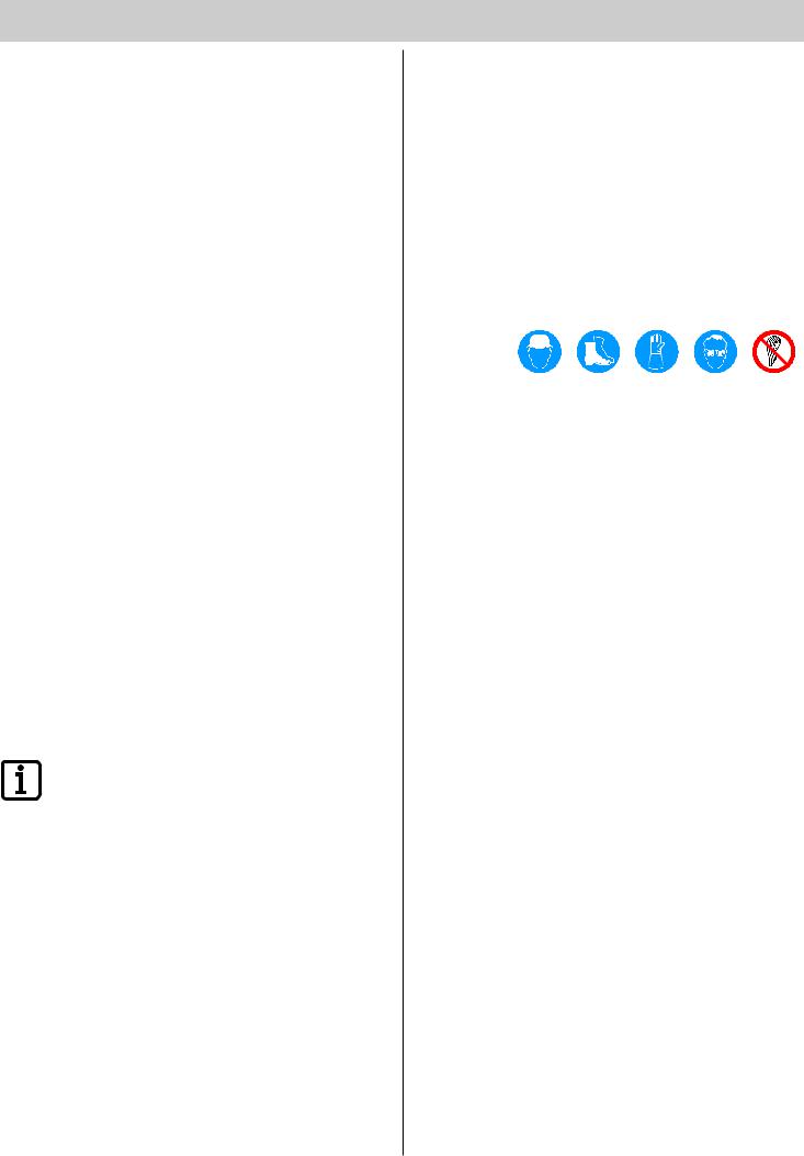
Personal safety equipment
The following table shows which protective equipment must be worn for the special work requirements and which safety measures must be taken.
|
|
|
|
|
|
Transport |
X |
X |
X |
|
X |
Installation |
|
X |
X |
X |
X |
|
|
|
|
|
|
Commissioning |
|
|
|
|
X |
|
|
|
|
|
|
Troubleshooting |
|
|
X |
|
X |
|
|
|
|
|
|
Disassembly |
|
X |
X |
X |
X |
Disposal |
X |
X |
X |
|
X |
|
|
|
|
|
|
Spare parts and accessories
Use only original spare parts or the spare parts of other manufacturers that have been approved by SOMMER Antriebsund Funktechnik GmbH.
If safety-relevant parts are replaced, their function must be checked afterwards.
Use only accessories approved by SOMMER Antriebsund
Funktechnik GmbH. The use of accessories can change the work with the barrier. In addition, observe the instructions for work and safety during the use of accessories.
– 6

Product description
Scope of supply
Standard scope of supply
The actual scope of supply may vary depending on the design of the barrier.
The standard scope of supply contains the following goods:
1 |
3 |
4 |
|
|
|
||
|
2 |
|
|
|
|
2x |
|
5 |
|
|
|
|
6 |
|
|
|
|
7 |
|
|
|
4x |
8 |
|
9 |
|
|
Item |
Quantity |
Description |
1 |
1 |
Barrier housing - left-closing or right-closing design |
2 |
2 |
U-profiles |
3 |
1 |
Faceplate of the boom cover |
4 |
1 |
Boom cover with 2 screws |
5 |
2 |
Springs - 2 factory-installed |
6 |
1 |
Boom |
7 |
1 |
Shim plate with 4 screws |
8 |
2 |
Keys of the barrier housing |
9 |
1 |
Installation and Operating Instructions |
Note:
The detailed list of the scope of supply can be found on the order form.
Available accessories
A number of accessories are available for the barrier. The accessories can be reordered at any time from SOMMER Antriebsund Funktechnik GmbH.
|
|
2 |
|
|
3 |
1 |
|
||||
|
|
|
1 |
0 |
|
|
|
|
|
||
|
|
|
|
|
|
|
|
|
|
2 |
|
|
|
|
SOMMER |
|
|
|
|
|
|
TORANTRIEBE |
|
5 |
4 |
|
6
9
11
8 10
7
Warning light
The users of the barrier are warned of an opening or closing barrier by the warning light.
Key switch
The barrier opens or closes when the key switch is activated.
Hand-held transmitter
Using the hand-held transmitter, the barrier is opened or closed by radio signal.
External antenna
The external antenna extends the reception range for radio signals.
Photo eye
The photo eye detects objects and sends a signal to the control system when something is detected. A closing of the barrier can be prevented, for example, if the photo eye is monitoring the closing range.
Main switch
The lockable main switch (all-pole line disconnector according to
EN 12453) de-energizes the barrier on all poles.
8.2 kOhm safety contact strip (electrical)
Note:
Either an 8.2 kOhm safety contact strip or an optical safety contact strip (OSE in the following) can be connected!
A connection of both safety devices is not possible!
If the 8.2 kOhm safety contact strip attached to the boom hits an obstacle during the closing procedure, the barrier stops and opens completely.
The C-rail required for installation is included.
– 7
Product description
Optical safety contact strip - OSE system
Note:
Either an 8.2 kOhm safety contact strip or an optical safety contact strip (OSE in the following) can be connected!
A connection of both safety devices is not possible!
If the 8.2 kOhm safety contact strip attached to the boom hits an obstacle during the closing procedure, the barrier stops and opens completely.
The C-rail required for installation must be purchased separately.
 Reflectors
Reflectors attached to the boom increase the visibility of the boom in the dark.

 Floating support (up to a maximum boom length of 5 meters)
In case of a boom length of 3 to 5 meters, either a floating support or a support post must be installed. In case of a boom length of more than 5 meters, a support post must be installed.
Support post
In case of a boom length of 3 to 5 meters, either a floating support or a support post must be installed. In case of a boom length of more than
5 meters, a support post must be installed.
 Loop evaluation
If induction loops are present on-site for the opening or closing of the barrier, their signals can be processed using loop evaluation.
Dimensions
All dimensions are in millimeters.
|
1 |
|
|
|
100 |
30 |
|
6000-1500 |
|
|
40 |
|
|
|
|
1080 |
|
|
975-775 |
|
250 |
350 |
150 |
150 |
|
|
|
||
|
|
|
|
Technical data
Weight without the boom |
40 kg |
Weight with the boom 6 m |
6 kg |
|
|
Maximum opening width |
5.55 m |
Weight of 5 m LED boom |
6 kg |
|
|
Max. opening width of LED boom |
4.55 m |
|
|
Opening time |
Max. 7 sec. |
|
|
Closing time |
Max. 7 sec. |
|
|
Voltage supply |
230 V; 50 Hz |
|
|
|
|
Motor |
24 V DC |
|
|
Power consumption in normal |
80 W |
operation |
|
Power consumption in standby |
Max. 2 W |
|
|
Dimensions without the boom |
H 1080 mm x W 350 mm |
|
x D 250 mm |
Dimensions of boom |
5/6 m, can be shortened to 1.5 m |
Protection type |
IP 44 |
|
|
Temperature range |
– 20 °C to + 60 °C |
Maximum wind strength according |
8 (stormy wind), |
to Beaufort scale |
corresponds to 20.6 m/s or 74 kph |
Permitted cycles |
Max. 300 cycles/day |
|
|
Type plate
The type plate is attached to the inside of the housing.
The following data is on the type plate:
•Company name and complete address of the manufacturer
•Designation of the machine
•CE mark
•Type designation and serial number
•Manufacturing date (month/year) of the barrier
– 8
Transport/unloading/storage
Transport
The barrier is transported to the operator by a specialist dealer or by a haulage company commissioned by the specialist dealer.
After the contractually regulated handover of all responsibility to
the operator, the operator must make sure that the barrier is safely and properly transported during transport.
The following information regarding transport absolutely must be observed:
¾¾ Do not stack the packaging units on top of each other.
¾¾ Transport the packaging units in the position specified on the packaging.
¾¾ Even during transport, observe the ambient conditions (temperature, humidity, etc.) required by the manufacturer.
¾¾ Always make sure that the barrier is transported without impacts and jolts.
¾¾ Always secure the loads to be transported against falling, tipping over, and damage.
Unloading and in-house transport
Warning
During this work, dangers may arise, for example, due to uneven surfaces, sharp edges, or the use of operating materials and adjuvants.
Body parts may be injured.
¾¾ Wear suited, closely fitting protective work clothes
(safety helmet, safety shoes, and safety gloves at minimum). Do not wear long hair loosely.
Danger Falling load!
During unloading, the load may fall and cause severe or deadly injuries.
¾¾ Use lifting equipment designed for the weight of the load.
¾¾ Never walk under suspended loads.
Check packaging units for externally recognizable transport damage or other damages. In case of damage, have it confirmed by the haulage company and inform SOMMER Antriebsund Funktechnik GmbH immediately in writing.
After unloading, store the barrier until setup. For this purpose, the operator of the barrier might have to transport the barrier for the place of unloading to the storage location.
In the process, observe the following information regarding unloading and intermediate transport:
¾¾ For unloading and in-house transport, at least two people are required.
¾¾ Only use suitable, tested, and standardized lifting equipment
(fork lift truck, mobile crane, overhead crane) and means of suspension
(slings, lifting belts, sling ropes, chains).
¾¾ When selecting the lifting equipment and means of suspension, always take the maximum load-bearing capacities into consideration.
¾¾ Always make sure that the barrier is unloaded and transported without impacts and jolts.
¾¾ Do not stack the packaging units on top of each other.
¾¾ After unloading, do not remove the packaging materials or transport safety devices.
Storage
Warning
The drive and other subassemblies of the barrier may be damaged by incorrect storage.
Irreparable damage to the barrier may be the result.
¾¾ Observe the following storage conditions at first delivery and intermediate storage!
The packaging units are packed in a plastic film for transport that protects them against environmental influences.
¾¾ Do not remove or damage this plastic film. If necessary, additionally cover the subassemblies.
¾¾ Store the packaging units in enclosed, dry rooms so that they are protected against moisture and UV radiation.
¾¾ Store the packaging units at a storage temperature from –20 °C to +60 °C.
¾¾ Store the packaging units in the position specified on the packaging.
¾¾ Do not stack the packaging units on top of each other.
¾¾ Leave room for unhindered passage.
– 9
Installation preparations
1
2 
 2 x 0,75 mm2
0  2
2
 4 x 0,75 mm


 3
3
2 x 0,75 mm2
|
|
5 |
|
|
|
8 |
|||||
|
|
|
|
||
|
|
|
|
||
|
|
|
|
4 |
|
|
|
|
|
|
|
7 |
|
|
|
|
|
|
|
|
|
|
|
AC 230 V
3 x
3
|
9 |
|
4 x 0,75 mm2 |
|
|
|
|
|
6
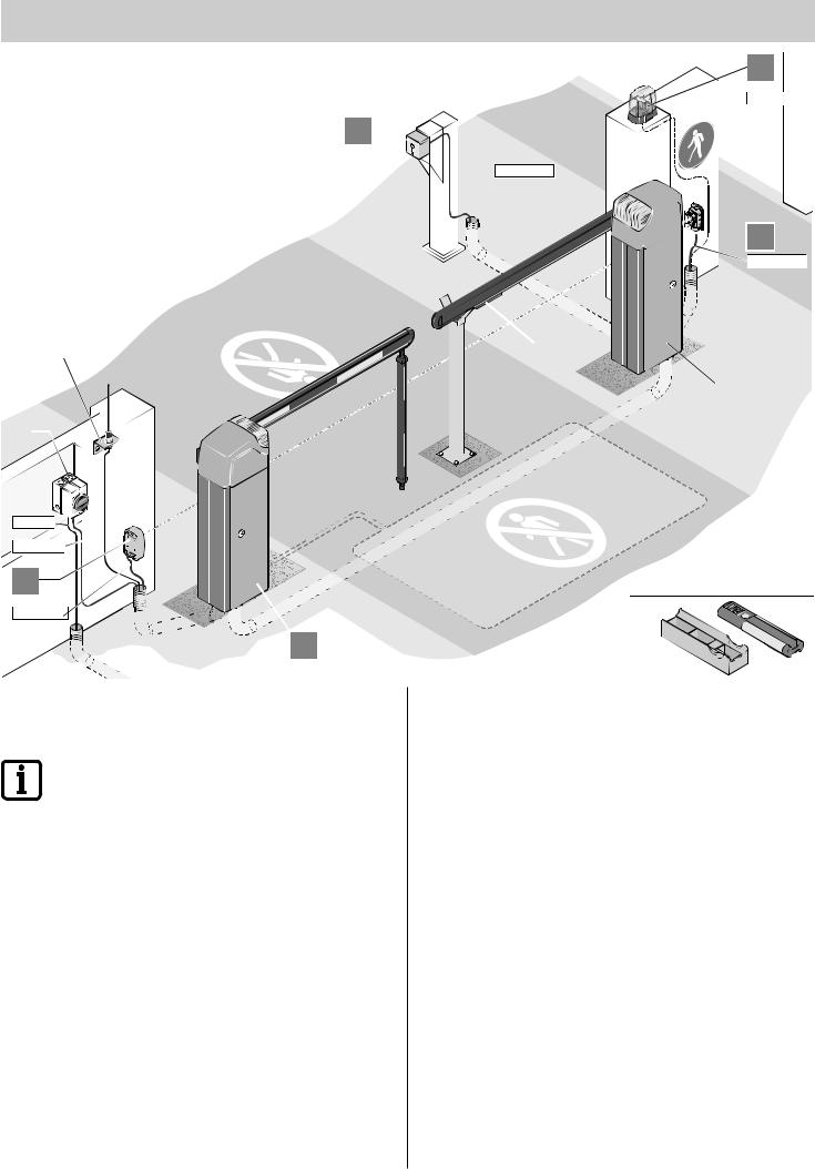
A possible installation scenario is shown here as an example.
Determine the position of the accessories before installation together with the operator.
|
|
Note! |
|
|
Further possible command initiators are Telecody and |
|
|
wireless indoor switches. In the case of Telecody or the |
|
|
wireless indoor switches, no connecting line must be |
|
|
installed for operation. Ask your specialist dealer. |
1 |
|
Warning light DC 24 V |
|
||
|
|
|
2 |
|
Key switch |
3 |
|
Photo eye |
|
|
|
4 |
|
Left-closing barrier |
5 |
|
8.2 kOhm safety contact strip or OSE system |
|
|
|
6 |
|
Right-closing barrier |
7 |
|
Main switch (lockable) |
|
|
|
8 |
|
External antenna (incl. 10 m cable) |
|
|
|
9 |
|
Hand-held transmitter with car/wall holder |
|
|
|
Before the installation of the barrier, organizational and on-site preparations must be made.
Observe the following information for the preparation of installation:
¾¾ The entire length of the boom is not equal to the effective opening width.
¾¾ For a boom length of more than 3 meters, a floating support or support post is required. Use floating supports only up to a maximum boom length of 5 meters.
¾¾ The barrier house and tip of the boom must have a safety distance of at least 500 mm to the next stationary obstacle (building, wall, fence, etc).
¾¾ Implement the mains connection according to EN 12453 (all-pole line disconnector). For this purpose, install a lockable main switch (all-pole deactivation).
¾¾ Operate barriers only with a permanently laid line secured with a fuse
(16 A, slow-acting). The mains cable connected in the delivery state is not approved for constant or outdoor operation.
¾¾ A minimum distance of 5 meters must be observed between the range of movement of the barrier and free lines/boom.
¾¾ Provide empty ducts in the foundation of the barrier and throughout the installation site for the cables of the mains supply line and the accessories (photo eye, warning light, key switch, etc.).
– 10
Installation preparations
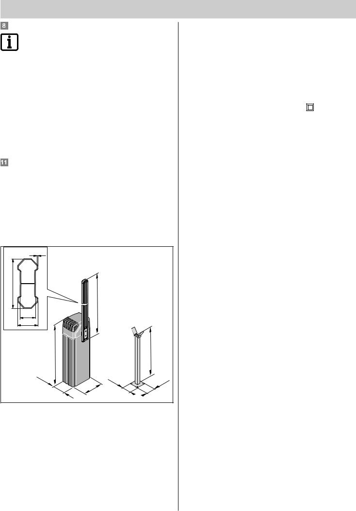
Installation drawing
Using the overview illustration, the position of the foundation, the length of the boom, and, if necessary, the position of the support post can be calculated.
≥ 500 |
X |
≥ 500 |
|
|
Y |
300 |
|
|
350 |
Z = X - 280 - Y |
|
X = Boom length (from 1500 mm to 6000 mm)
Y = Distance from the tip of the boom to the center of the support post or floating support. Minimum of 150 mm, maximum of 300 mm
Z = Opening width of the barrier - drive-through width
Sample calculation:
Calculation of the boom length (X) at:
Opening width of the barrier (Z) = 3500 mm
Distance between the tip of the barrier and the center of the support post (Y) = 200 mm
X = Z + Y + 280 mm
X = 3500 mm + 200 mm + 280 mm
X = 3980 mm
Creation of barrier foundation with supply connections
For the proper operation of the barrier, the barrier housing must stand securely.
The following table shows the minimum foundation size and the foundation size recommended by SOMMER Antriebsund Funktechnik GmbH.
According to the danger of frost, the depth of the foundation (D) must be adapted in a frost-proof manner so that the ground cannot lift.
L |
|
800≥T |
|
|
|
≥ |
|
|
|
|
|
400 |
|
|
|
|
|
|
D |
|
W |
|
L |
|
|
|
|||
Minimum size |
Frost-proof! |
|
300 mm |
|
400 mm |
|
In Germany, 800 mm |
|
|
|
|
Recommended |
1,000 mm |
|
400 mm |
|
400 mm |
|
|
|
|
|
|
Conduct all required empty ducts and lines from the middle of the foundation. When selecting empty duct, take all lines to be laid into consideration.
This may be as follows:
•Power supply line
•Connecting line for the photo eye/induction loop
•Connecting line for the stationary command initiators
•Connecting line for accessories like the warning light, external antenna, etc.
Warning
Never lay the power supply line in the same duct as the connecting lines.
Interference in the control system may result.
¾¾ Use different empty ducts for the power supply line and the connecting lines.
Only use lines/cables suitable for the outdoors (cold resistance,
UV-resistance).
The surface of the foundation must be even and absolutely horizontal to the lane (smoothened) so that the barrier housing can be set up evenly.
Use concrete with the following strength class:
–– EN 206 C25/30 XC4, XF1, XA1 (25-30 N/mm²)
The foundation must be massive and steel-reinforced.
The barrier housing is attached using heavy-duty anchors (not included in delivery).
Minimum size of the heavy-duty anchor M10x120 or M12x125.
Note:
For more information regarding heavy-duty anchors, contact your specialist dealer.
Creating the foundation of the support post
A stable foundation is required for the installation of the support post.
The minimum size for the foundation is specified in the following table.
According to the danger of frost, the depth of the foundation (D) must be adapted in a frost-proof manner so that the ground cannot lift.
D |
W |
L |
Frost-proof! |
200 mm |
200 mm |
In Germany, 800 mm |
|
|
The surface of the foundation must be even and absolutely horizontal to the lane (smoothened) so that the barrier housing can be set up evenly.
Use concrete with the following strength class:
–– EN 206 C25/30 XC4, XF1, XA1 (25-30 N/mm²)
The barrier housing is attached using heavy-duty anchors (not included in delivery).
Minimum size of the heavy-duty anchor M8x75 or M10x85.
Note:
For more information regarding heavy-duty anchors, contact your specialist dealer.
– 11

Installation preparations
Stationary command initiators
The stationary command initiators (key switch, pushbutton, etc.) must be placed in such a way that
•They can be reached easily from any vehicle.
•The user is not in the range of movement of the barrier.
•The user has direct visual contact with the barrier during actuation.
Safety measures
For the safe operation of the barrier, the operator must install the necessary safety devices. Using suitable measures, the opening and closing movements must be monitored.
The following are suited to this purpose:
•Photo eyes
•Induction loops
•8.2 kOhm safety contact strip or OSE system
Note:
Up to two safety devices can be connected to the control system! A safety device must always be connected as an NC contact so that safety is always guaranteed in case of a defect.
For example, various safety device scenarios are shown in the "Appendix -
Entrance and Exit Scenarios" chapter.
Pedestrian traffic
The ASB-6010A / ASB-5014A barrier may only be used for vehicle traffic.
People may not use the barrier.
The operator must use suitable measures to guarantee a strict separation of vehicle and pedestrian traffic. Structural separations like pedestrian paths next to the lane must be supplemented with warnings and corresponding signs.
Tools required
The following tools must be available for proper installation:
8 mm |
13 mm |
4x |
10 mm |
17 mm |
|
12 mm |
19 mm |
|
– 12

Installation
Safety information for installation
¾¾ Perform installation only up to a maximum wind strength of 3 on the
Beaufort scale (light wind).
¾¾ At least two people are required for the entire installation.
¾¾ For installation work performed above body height, used suitable, tested, and stable climbing aids. Never use the barrier or parts of the barrier as climbing aids.
¾¾ Check all screws and terminals in and on the barrier for a firm seat and tighten them, if necessary.
¾¾ The installation of the barrier and all work on the electric system may only be performed by the personnel described in the "Safety
Information - Qualification of the Personnel" chapter.
Danger of tipping!
The barrier may tip during installation and in-house transport. People can be injured and the barrier can be damaged.
¾¾ Transport and installation may be performed only with two people and suitable transport equipment.
Check the scope of supply
Remove the barrier and all accessories from the packaging at the installation site. No sharp objects may be used to open the packaging since parts could otherwise be damaged.
Check the delivery for completeness (see the "Product Description - Scope of Delivery" chapter and order form).
In case of an incomplete delivery, contact your specialist dealer or
SOMMER Antriebsund Funktechnik GmbH.
Dispose of the packaging according to locally applicable regulations.
Installation of the barrier housing
1. Pull the cables into the empty ducts and label them for later allocation.
2.Remove the drill template from this manual (see the "Appendix - Drill Template" chapter), place it on the foundation, and draw in four holes.
10 mm |
|
12 mm |
10 mm |
|
12 mm |
|
≥65mm |
3. Drill four holes Ø 10 or Ø 12 mm at least 65 mm deep.
4. Blow out holes with compressed air.
Note:
Only use permissible fastening materials. For the recommended heavy-duty anchors, see the "Installation Preparations - Creation of Barrier Foundation with Supply Connections" chapter.
5.Insert four heavy-duty anchors into the holes.
6.Put the barrier housing into place and open the door.
Note:
Remove the control system and put it aside. Do not reinstall the control system until after the connection to the power mains.
7.Insert both U-profiles.
8.Align the barrier housing or U-profiles. Put four washers into place and tighten four nuts. With the spirit level, check the horizontal alignment of the barrier and correct it if necessary.
9.Close the barrier house.
– 13

Installation
Adapting the length of the boom
Note:
The entire length of the boom is not equal to the effective opening width!
Note:
When using a LED boom do not damage cables and LED bars when sawing
To calculate the required length of the boom, see the "Installation Preparations - Installation Drawing/Sample Calculation" chapter.
1. Remove the cover from the tip of the boom.
2.Cut the boom to the desired length and deburr it if necessary.
3.Place the cover onto the tip of the boom.
Installation of the boom
Note:
When using a floating support, install it before installing the boom. See the "Installation - Installation of the Floating Support" chapter.
1. The boom is attached in the vertical opening position.
 2x
2x 

max. |
|
10 Nm |
|
4x |
2x |
2.Place the boom onto the boom holder, put a shim plate on it, and fasten with four screws.
3.Install the cover with two screws and put the faceplate into place.
Installation of a LED boom
Note:
A floating support cannot be used with the LED boom!
Use a supporting post for a boom length between 3 and 5 m
1. The boom is attached in the vertical opening position.
 2x
2x 

max. 10 Nm

 4x
4x
2.Insert the cables of the LED boom into the hold in the boom holder.
3.Attach th boom to the boom holder, attach the washer and fix it with 4 srews.

 2x
2x
4. Install the cover with two screws and put the faceplate into place.
5.Insert cables into housing from shaft. Install the rubber grommet correctly.
6.Insert cables inside the barrier housing through the base plate cable gland.
– 14
 Loading...