


Installation and Operating Instructions 1 - 29STArter
46755V001-052012-0-OCE-Rev.A

Table of contents
General Information....................................................... |
3 |
Symbols............................................................................................ |
3 |
Safety instructions............................................................................ |
3 |
Intended use..................................................................................... |
4 |
Permitted gate wing dimensions....................................................... |
4 |
Technical data................................................................................... |
4 |
Dimensions....................................................................................... |
4 |
General Information....................................................... |
5 |
Installation preparations............................................... |
6 |
Safety instructions............................................................................ |
6 |
Tools required................................................................................... |
6 |
Personal safety equipment............................................................... |
6 |
Scope of supply................................................................................ |
6 |
Installation...................................................................... |
7 |
Tips for installation............................................................................ |
7 |
General preparations........................................................................ |
7 |
Safety instructions............................................................................ |
8 |
Installation on ground....................................................................... |
8 |
Foundation........................................................................................ |
8 |
Installing the console........................................................................ |
9 |
Console............................................................................................. |
9 |
Installing drive on console................................................................ |
9 |
Installing the racks............................................................................ |
9 |
Mains connection............................................................................. |
11 |
Installation location.......................................................................... |
11 |
Connection ................................................................... |
11 |
Set door end position CLOSED...................................................... |
12 |
Set door end position OPEN........................................................... |
12 |
Connecting buttons or key switches............................................... |
12 |
What is button 2 for?....................................................................... |
13 |
Safety instructions.......................................................................... |
13 |
Connecting photo eyes................................................................... |
13 |
Safety............................................................................ |
13 |
Connecting safety contact strip....................................................... |
14 |
Safety instructions.......................................................................... |
14 |
Warning light................................................................................... |
14 |
24 V connection.............................................................................. |
14 |
12 V connection.............................................................................. |
14 |
Additional connection options................................... |
14 |
Floating relay output....................................................................... |
15 |
Connecting external antenna.......................................................... |
15 |
TorMinal interface........................................................................... |
15 |
Special functions............................................................................. |
15 |
General information........................................................................ |
15 |
Overview of the control system....................................................... |
15 |
Connections................................................................. |
15 |
Safety instructions.......................................................................... |
16 |
Programming the drive................................................................... |
16 |
Resetting the control system.......................................................... |
16 |
Initial operation............................................................ |
16 |
Adjusting the force tolerance.......................................................... |
17 |
Programming the hand-held remote control................................... |
17 |
Initial operation............................................................ |
17 |
Safety instructions.......................................................................... |
18 |
Display and button explanation....................................................... |
18 |
External antenna............................................................................. |
18 |
Functions and connections........................................ |
18 |
Programming the hand-held remote control................................... |
19 |
Deleting the hand-held transmitter from the radio receiver............. |
19 |
Deleting a channel from the radio receiver..................................... |
19 |
Deleting the radio receiver memory................................................ |
19 |
DIP switches................................................................................... |
19 |
Functions and connections........................................ |
19 |
Obstacle detection (DIP 1, 2 + 3).................................................... |
20 |
Automatic closing function.............................................................. |
20 |
Functions and connections........................................ |
20 |
Prewarning time (DIP 5)................................................................. |
21 |
Fraba system (DIP 6)...................................................................... |
21 |
Defined opening and closing (DIP 7).............................................. |
21 |
Partial opening (DIP 8)................................................................... |
21 |
Safety instructions.......................................................................... |
22 |
Open door....................................................................................... |
22 |
Close door...................................................................................... |
22 |
Pulse sequence of door movement................................................ |
22 |
Control unit reset............................................................................ |
22 |
Break-in protection due to automatic lock....................................... |
22 |
Operation and control.................................................. |
22 |
Emergency release......................................................................... |
23 |
Overload protection........................................................................ |
23 |
Operation after a power failure....................................................... |
23 |
Operation / Use............................................................. |
23 |
Maintenance and care.................................................. |
24 |
Safety instructions.......................................................................... |
24 |
Regular testing................................................................................ |
24 |
Change the fuse............................................................................. |
25 |
Maintenance and care.................................................. |
25 |
Miscellaneous............................................................... |
26 |
Tips on troubleshooting.................................................................. |
26 |
Disassembly................................................................................... |
27 |
Disposal.......................................................................................... |
27 |
Troubleshooting........................................................... |
27 |
Connection diagram.................................................... |
29 |
– 2
General Information
Symbols
Attention symbol:
Important safety instructions!
To ensure personal safety, it is important to observe all instructions. Save these instructions!
Note symbol:
Information, useful advice!
Refers to a respective picture in the introduction or main text.
Safety instructions
General
•These installation and operating instructions must be read, understood and complied with by persons who install, use or perform maintenance on the drive.
•Keep this installation and operating manual accessible at all times.
•Installation, connection and initial commissioning of the drive may only be carried out by technically knowledgeable persons.
•Install the drive on correctly aligned gates only. An improperly aligned door can cause serious injuries or damage the drive.
•The manufacturer assumes no liability for injuries, damage or breakdowns that occur due to non-compliance with the installation and operating instructions.
•Always ensure compliance with accident prevention regulations and current standards in each respective country.
•Follow and comply with the "ASR A1.7 Technical Regulations for Workplaces" of the committee for workplaces (ASTA) (Applies to operators in Germany).
•Before any work on the drive disconnect it from the power supply and lock it to prevent reconnection.
•Only use OEM (Original Equipment Manufacturer) spare parts, accessories and mounting material.
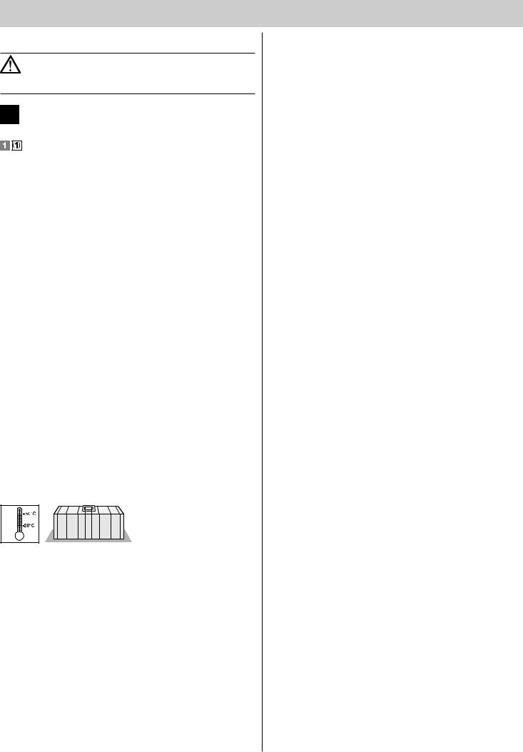
Storage
•The drive must be stored in an enclosed, dry area at a room temperature of -20 – +50 °C.
•The drive should be stored horizontally.
Operation
•The drive must be operated only if a non-hazardous force tolerance is set or safety is guaranteed by other safety equipment. The force tolerance must be set low enough to eliminate any danger of injury by the closing force (see "Maintenance and care").
•A rubber strip must be attached to secure the closing edge.
•Never put your hand near the door when it is moving or near moving parts.
•Drive through the gate only when it has opened completely.
•There is a risk of persons being crushed or cut by the mechanism or sharp edges of the door.
•For automatic closing the main and auxiliary closing edges must be secured in accordance with the applicable directives and standards.
•Open and close the gate only if there are no children, persons, animals or objects within its range of motion.
•Regularly check the safety and protection functions and repair faults when they are detected. See Care and maintenance.
Radio remote control
•The remote control must only be used for devices and systems in which radio interference will not endanger people, animals or objects or the risk is reduced by other safety devices.
•The user must be made aware that systems that pose an accident risk should only be operated – if at all – by remote control if the user can actually see the door.
•The radio remote control may only be used if the door’s movement can be watched and no persons or objects are within the range of movement.
•Store the hand-held transmitter so that unintended operation, e.g., by children or animals, is impossible.
•The operator of the radio system is not protected from faults due to other telecommunications equipment or devices (e.g. radio-controlled systems that are licensed to operate in the same frequency range).
If substantial interference occurs, please contact your appropriate telecommunications office which has radio interference measuring equipment (radiolocation).
•Do not operate the hand-held transmitter in areas with sensitive radio communications or systems (e.g. airports, hospitals).
Type plate
•The type plate is attached to the inside of the base frame/housing.
The type plate shows the exact type drawing and the date of manufacture (month/year) of the drive.
– 3
General Information
Intended use
•The drive is designed exclusively for opening and closing sliding gates
(see EN 12433-1), referred to below as gates. Any other use does not constitute intended use. The manufacturer accepts no liability resulting from use other than intended use. The user bears the sole responsibility for any risk involved. It also voids the warranty.
•Doors automated with an operator must must comply with the valid standards and directives: e.g. EN 12604, EN 12605.
•Maintain the safety clearances between the gate and surroundings as specified in EN 12604.
•The drive must be in good technical condition, and it must be used for its intended purpose with awareness of the hazards as described by the installation and operating manual.
•The gate must not have any rise or fall during opening or closing.
•Position the running rail to allow water to drain to prevent ice accumulation in winter.
•The gate must move freely in the guide and on the running rail to allow the drive to react sensitively and the gate to be switched off in emergency.
•The gate must have end stops in open and closed position, otherwise it may be pushed out of the guide in the event of an emergency release.
•Malfunctions which could affect safety must be corrected immediately.
•The door must be stable and rigid, meaning that it may not bend or twist when being opened or closed.
•The drive cannot compensate for defects in the door or incorrect assembly or installation.
•Do not install drive in explosive areas.
•Do not operate drive in rooms with aggressive atmosphere.
For the Declaration of Conformity for the radio see:
www.sommer.eu/mrl
Permitted gate wing dimensions
Min. path |
min. 1,400 mm |
||
Max. path: |
max. 6,000 mm |
||
|
|
|
|
Weight: |
max. 300 kg |
|
|
Gate inclination: |
0 % |
|
|
Technical data |
|
||
Rated voltage |
|
|
220 ...240 AC/V |
|
|
||
Rated frequency |
|
|
50/60 Hz |
|
|
|
|
Operating temperature range |
|
-20 – +50 °C |
|
|
|
|
|
Degree of protection |
|
|
IP 54 |
Max. tension and compress. force |
|
550 N |
|
|
|
|
|
Rated tension force |
|
|
165 N |
Rated current consumption |
|
0.22 A |
|
|
|
|
|
Rated wattage |
|
|
51 W |
Max. speed |
|
|
200 mm/s |
|
|
|
|
Power consumption, stand-by |
|
2 W |
|
Weight |
|
|
8 kg |
|
|
|
|
Operating time |
|
|
30 % |
|
|
|
|
Workplace-related emission value < 75 dBA - drive only
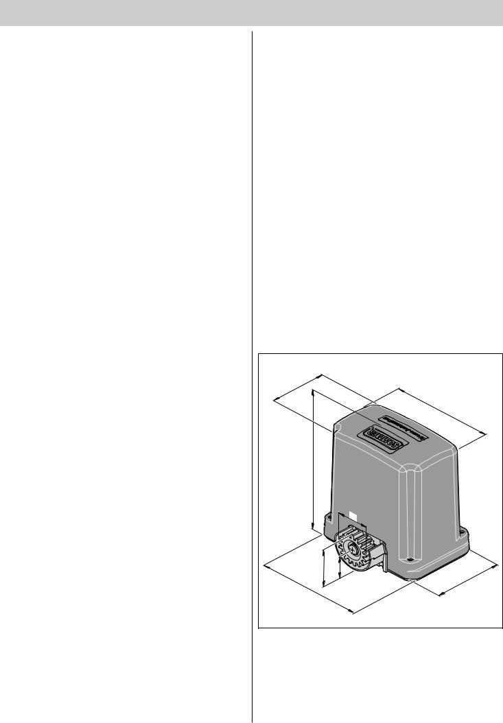
Dimensions
All dimensions are in millimeters. The drive is locked.
140,5 |
|
|
5 |
|
235, |
9 |
|
28 |
|
|
76 |
87 |
49 |
|
169 |
|
254 |
– 4

General Information
Declaration of Installation
for the installation of an incomplete machine
in accordance with the Machinery Directive 2006/42/EC, Appendix II, Section 1 B
SOMMER Antriebsund Funktechnik GmbH Hans - Böckler - Straße 21 - 27
73230 Kirchheim unter Teck Germany
hereby declares that the controller
STArter
as of the identification STArter complies with the Machinery Directive 2006/42/EC and is specified for installation in a gate system.
•The following fundamental safety requirements have been applied and observed in accordance with Appendix I:
-General principles No. 1
-1.2 Safety and reliability of control units
Safety input I terminals 6 + 7: Cat 2 / PL C
Optical safety contact strip terminals 6 + 20 + 21: Cat 2 / PL C
Electric 8.2 kΩ safety contact strip terminals 6 + 7: Cat 2 / PL C
Safety input II terminals 8 + 9: Cat 2 / PL C
Internal force limitation Cat 2 / PL C
Safety categories in accordance with EN 13849 - 1:2008
•Compliant with the regulations of the EC Building Products Guideline 89/106/EC.
For the operating forces part, the respective initial testing has been carried out in consultation with recognized inspecting authorities. In doing so, the harmonized standards EN 13241-1, EN 12453 and EN 12445 have been applied. For the tested combinations, refer to the "Reference list" table in the Internet under www.sommer.eu.
•Compliant with the Low Voltage Directive 2006/95/EC.
•Compliant with the Directive on Electromagnetic Compatibility 2004/1 08/EC.
•The technical documentation was drawn up in accordance with Appendix VII B.
The product may only be put into operation after it has been established that the door system complies with the regulations of the Machinery Directive.
Kirchheim, 01.02.11
Jochen Lude
Responsible for documents
– 5

Installation preparations
Safety instructions
Attention!
Follow all installation directions. Improper installation may cause serious injuries.
•The voltage of the power source must correspond with the voltage listed on the drive type plate.
•The contacts of all devices to be connected externally must be safely isolated from the mains voltage supply according to IEC 364 4 41.
•Wires for external devices must be installed in accordance with
IEC 364 4 41.
•The drive may only be installed, connected and commissioned by qualified technicians.
•Do not move the gate if there are people, animals or objects in the area of movement.
•Keep children, disabled persons and animals away from the gate.
•Wear safety glasses when drilling the fastening holes.
•Cover the drive during drilling to prevent penetration of dirt.
Attention!
The foundation must be solid and stable. Only install the drive on a correctly aligned door. An incorrectly aligned door could cause serious injury.
•Doors must be stable in themselves, since high traction and compression forces are encountered. Reinforce lighter doors made of plastic or aluminum if necessary before installation. Ask a specialist retailer for advice.
•Remove or disable door locks.
•Use only approved fasteners (e.g. anchor fittings, bolts). The fasteners must match the material of the ground.
•Check that the door runs smoothly.
Tools required
5 mm |
10 mm |
10 mm |
|
8 mm |
13 mm |
Personal safety equipment
•Safety glasses (for drilling).
•Work gloves.
Scope of supply
•Check the package before installation to avoid unnecessary work and expense if a part is missing.
•The actual scope of supply may vary depending on the design of the drive.
6 |
|
|
1 |
|
|
|
|
5 |
|
|
2 |
|
|
|
3 |
4x |
|
|
|
24x |
|
Bedienungsanl |
|
|
eitung |
|
|
|
D |
|
|
|
|
1 |
|
|
|
|
4 |
8 |
7 |
24x |
|
|
|
Complete set
Package (L x W x H) |
1035 × 350 × 270 mm |
||
|
|
|
|
Weight |
|
12 kg |
|
1. |
1 item |
Sliding gate drive with controller and radio receiver |
|
|
|
|
|
2. |
1 item |
Console |
|
|
|
|
|
3. |
1 item |
Installation and Operating Instructions |
|
4. |
1 item |
4 Hand-held command transmitter |
|
|
|
|
|
5. |
4 item |
1 m rack |
|
6. |
2 item |
Limit switch |
|
|
|
|
|
7. |
1 item |
4 item Auxiliary mounting plate |
|
|
|
2 item Spring washer |
|
|
|
2 item Screw |
|
|
|
2 item U-washer |
|
|
|
2 item Lock washer |
|
|
|
2 item Key |
|
8. |
1 item |
Installation bag (fasteners) |
|
|
|
24 item Screw |
|
|
|
24 items Washers |
|
|
|
|
|
Single drive
Package (L x W x H) |
400 × 355 × 225 mm |
||
|
|
|
|
Weight |
|
8 kg |
|
|
|
|
|
1. |
1 item |
Sliding gate drive with controller and radio receiver |
|
|
|
|
|
2. |
1 item |
Console |
|
3. |
1 item |
Installation and Operating Instructions |
|
|
|
|
|
8. |
2 item |
Key for cover |
|
6. |
2 item |
Solenoid limit switch |
|
|
|
|
|
– 6

Installation
|
|
1 |
8 |
|
|
|
|
|
2 x 0,75 mm2
0 |
2 |
1 |
|
ER |
|
SOMM |
|
2
4 x 0,75 mm2
 3
3
2 x 0,75 mm2
7
2 x 0,75 mm2
6
5
AC 230 V 3 x
3
4 x 0,75 mm2
Tips for installation
•A safety device must always be connected as a NC contact. This ensures that safety is always guaranteed in the event of tripping or a fault.
•Determine the position of the accessories before installation together with the operator.
Note!
Additional pulse transmitters are: hand-held transmitters, Telecody, wireless indoor switches and key switches. In the case of the hand-held transmitter, Telecody or the wireless indoor switches a connecting line to the drive is not required (contact your dealer).
1.Warning light DC 24 V
2. |
Key switch (1 or 2 contact) |
|
|
3. |
Photo eyes (required for automatic closing, see EN 12543) |
|
|
4. |
Console |
|
|
5. |
Main switch (lockable) |
6. |
Rod antenna (with 10 m cable) |
|
|
7. |
Safety contact strip (8.2 kOhm, Fraba system) |
8. |
Telecody |
9.Car/wall holder for hand-held transmitter
General preparations
•Remove or disable all locking devices (electric lock, bars, etc.) before installing the drive.
•The gate must have a stable structure and must be suitable.
•The gate must not show excessive lateral deviation throughout its range of movement.
•The system wheels and bottom track and the roller and top guide must operate without excessive friction.
•End stops must be installed at the "gate OPEN + gate CLOSED" positions to prevent derailing of the gate.
•Install empty ducts under the gate for the cables of the mains supply line and the accessories (photo eye, warning light, key switch, etc.).
– 7
Installation
Safety instructions
•The control unit must be connected to the power supply by an electrician only.
•Ensure that the drive is securely fastened to the ground and the racks on the gate to withstand the high forces generated when opening and closing the gate.
•If a button is used for opening or closing, it must be installed at a height of at least 1.6 m to prevent operation by children.
•The rack must not press on the pinion during operation, otherwise the drive will be damaged.
•Follow the standards for installation, e.g.: EN 12604, EN 12605.
Installation on ground
Note
Dispose of packaging according to your local regulations.
40
19
94 |
138 |
8 |
|
|
|
|
|
59 |
59 |
|
|
Foundation
•For free-standing gates install the drive centrally between the roller blocks.
•The foundation must extend below the frost line (approx. 800 mm in Germany).
•The foundation must be cured and horizontal.
•Foundation dimensions as shown.
310 |
|
195 |
|
350 |
95 |
|
|
– 8

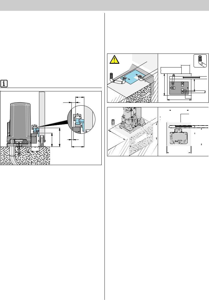
Installation
Installing the console
1.Check the scope of supply
2.Remove the drill template from the middle of this manual
3.Mark the holes on the foundation with the drill template
4.Make drill holes
5.Insert anchor fittings
6.Screw down console
Console
Note!
Always note the dimensions and angles, see “Installation location”.
|
m |
60, |
5 |
|
7.Note the dimensions of the console and cable ducts for the mains connection and accessories (e.g. photo eye) during excavation, see "Foundation".
8.Check the dimensions and the horizontal position of the console. Screw down or concrete in cable ducts and console.
Installing drive on console
2 |
3 |
1 |
9.Unscrew the four screws (1) and remove cover (2).
10.Remove controller (3).
11.Screw drive to console. Use the mounting plates (30 x 20 x 1.5 mm) to set a distance of 1.5 mm in between drive and console. This allows optimum adjustment of the gear play.
Releasing drive
2 |
1 |
3 |
12.Lift protective cover (1).
13.Insert key and turn.
14.Lift cover to the outside.
15.Drive is released and the gate can be moved manually.
Installing the racks
Attention!
Steel racks must have a minimum width of 12 mm.
Narrower steel racks may damage the drive.
Note!
The complete kit contains four racks each 1 m long.
Contact your dealer if you require more racks.
•The rack must not press on the pinion at any position during operation, otherwise the gears will be damaged.
•Always start installing the rack on the passage side of the gate.
•The holes must always be marked near the pinion.
– 9 |
 Loading...