


EN TRANSLATION OF THE ORIGINAL INSTALLATION AND OPERATING MANUAL
Garage door operator
S 9050 base / S 9050 base+
S 9060 base / S 9060 base+
S 9080 base / S 9080 base+
S 9110 base / S 9110 base+
Download the current manual:
base-plus_46900V001_192019_0-DRE_Rev-E_EN

Dear customer,
Congratulations on your purchase of a product of SOMMER
Antriebs- und Funktechnik GmbH.
This product has been developed and manufactured under
high standards of quality and with reference to ISO 9001.
Our passion for the product is just as important to us as
the needs and requirements of our customers. We place
particular emphasis on the safety and reliability of our products.
Read this installation and operating manual carefully and
follow all instructions. This will ensure that you can install
and operate the product safely and optimally. If you have
any questions, please contact your specialist retailer or
installer.
Our products are intended for use by persons of all genders, even where this is not specifically stated.
Warranty
The warranty complies with statutory requirements.
7KHFRQWDFWSHUVRQIRUZDUUDQWLHVLVWKHTXDOL¿HGGHDOHU
The warranty is only valid in the country in which the operator was purchased. There is no warranty for consumables
such as batteries, accumulators and fuses as well as light
bulbs. This also applies for wear parts. The operator is only
designed for a limited frequency of use. More frequent use
leads to increased wear.
Contact data
If you require after-sales service, spare parts or accessories,
SOHDVHFRQWDFW\RXUTXDOL¿HGVSHFLDOLVWUHWDLOHURULQVWDOOHU
Feedback on this Installation and Operating Manual
We have tried to make the Installation and Operating Manual as easy as possible to follow. If you have any suggestions as to how we could improve it or if you think more
information is needed, please send your suggestions to us:
+49 (0) 7021 8001-403
doku@sommer.eu
Service
If you require service, please contact us on our service hotline (fee required) or see our web site:
+49 (0) 900 1800-150
(0.14 euros/minute from landline telephones
in Germany, mobile prices may vary)
www.sommer.eu/de/kundendienst.html
Copyright and proprietary rights
The manufacturer retains the copyright for this Installation and Operating manual. No part of this Installation and
Operating Manual may be reproduced in any form or processed, copied, or distributed using electronic systems
without the written permission of SOMMER Antriebs- und
Funktechnik GmbH. Violations of the above stipulations
will lead to damage claims. All brands mentioned in this
Installation and Operating Manual are the property of their
respective manufacturer and hereby recognised as such.
Table of contents
1. About this Installation and Operating Manual 4
1.1 Storage and circulation of the Installation and
Operating Manual 4
1.2 Important for translations 4
1.3 Description of the product type 4
1.4 Target groups of the Installation and Operating
Manual 4
1.5 Explanation of symbols and notes 4
1.6 Special warning symbols and mandatory signs 5
1.7 Information regarding the depiction of text 5
1.8 Intended use of the operator 5
1.9 Improper use of the operator 6
1.10 Qualifications of personnel 6
1.11 Information for the user 7
2. General safety instructions 8
2.1 Basic safety instructions for operation 8
2.2 Additional safety information for the radio
remote control 9
2.3 Notes and information on operation and radio
remote control 9
2.4 Simplified Declaration of Conformity for radio
systems 9
3. Description of function and product 10
3.1 The operator and its mode of operation 10
3.2 Safety equipment 10
3.3 Product designation 11
3.4 Explanation of tool symbols 11
3.5 Scope of delivery 12
3.6 Dimensions 13
3.7 Technical data 13
3.8 Overview of connection options 14
4. Tools and protective equipment 15
4.1 Required tools and personal protective
equipment 15
5. Declaration of Installation 15
6. Installation 16
6.1 Important notes and information 16
6.2 Preparing for installation 17
6.3 Installing the drive system 18
6.4 Installation on the door 20
7. Removing and fastening covers 24
7.1 Cover of the motor carriage 24
7.2 Cover of the ceiling control unit 24
8. Electrical connection 26
8.1 Connection to a power outlet 26
9. Initial operation 27
9.1 Important notes and information 27
9.2 Carrying out automatic initial operation 27

Table of contents
9.3 Carrying out manual initial operation 29
9.4 Detecting obstacles during the force
programming run 29
9.5 Mechanical adjustment of the end positions 30
9.6 Attaching information sign and warning signs 31
10. Connections and special functions
of the motor carriage 32
10.1 Motor carriage circuit board 32
10.2 Connection options on the motor carriage 33
10.3 Reducing the illumination power of LEDs 34
10.4 Explanation of the radio channels 34
10.5 Programming the transmitter 34
10.6 Information on Memo 35
10.7 Cancelling programming mode 35
10.8 Deleting a transmitter button from the radio
channel 35
10.9 Deleting transmitter completely from
the receiver 35
10.10 Deleting a radio channel in the receiver 35
10.11 Deleting all radio channels in the receiver 36
10.12 Programming a second handheld transmitter
by radio (HFL) 36
10.13 Carrying out a reset 36
10.14 Setting the DIP switches on the motor carriage 37
10.15 Setting automatic closing function – defining
basic values 37
10.16 Setting the lighting function 38
10.17 Setting partial opening 38
10.18 Deleting partial opening 38
10.19 Wicket door safety device 38
10.20 Connecting the safety contact strip 39
10.21 12 V output 39
10.22 SOMlink 39
13. Operation 49
13.1 Important notes and information 49
13.2 Handover to the user 49
13.3 Operating modes of door movement 50
13.4 Obstacle detection 50
13.5 Power-saving mode 50
13.6 In the event of a power failure 51
13.7 Function of the emergency release 51
14. Maintenance and care 52
14.1 Important notes and information 52
14.2 Maintenance schedule 53
14.3 Care 53
15. Troubleshooting 54
15.1 Important notes and information 54
15.2 Preparing for troubleshooting 55
15.3 Time sequences of operator lighting in normal
mode and in case of faults 56
15.4 Troubleshooting table 57
15.5 Replacing the motor carriage 58
16. Taking out of operation, storage and
disassembly 59
16.1 Important notes and information 59
16.2 Taking out of operation and disassembly 59
16.3 Storage 59
16.4 Disposal of waste 59
17. Short instructions for installation 61
18. Connection diagrams and functions
of the DIP switches for base/base+ 64
11. Connections and special functions
of the ceiling control unit 40
11.1 Ceiling control unit circuit board 40
11.2 Connection options of the ceiling control unit 41
11.3 Setting the DIP switches on the ceiling
control unit 42
11.4 Button 2 for partial opening 42
11.5 Photocell and frame photocell 43
11.6 Wallstation 44
11.7 Conex 44
11.8 Output OC 45
11.9 Relay 45
11.10 Installing and removing the accumulator 45
12. Function test and final test 47
12.1 Testing obstacle detection 47
12.2 Handover of the door system 48
3

1. About this Installation and Operating Manual
1.1 Storage and circulation of
the Installation and Operating Manual
Read this Installation and Operating Manual carefully and
completely before installation, commissioning and operation and also before removal. Observe all warnings and
safety instructions.
Keep this installation and operating manual accessible
to all users at all times at the place of use. A replacement
for the installation and operating manual can be downloaded from SOMMER at:
www.sommer.eu
During the transfer or resale of the operator to third parties, the following documents must be passed on to
the new owner:
• EC Declaration of Conformity
• handover protocol and inspection book
• this Installation and Operating Manual
• proof of regular maintenance, testing and care
• documents recording retrofitting and repairs
1.2 Important for translations
The original installation and operating manual was written
in German. The other available languages are translations of the German version. You can get the original
installation and operating manual by scanning
the QR code.
• unloading and in-house transport
• unpacking and installation
• initial operation
• setting
• usage
• maintenance, testing and care
• troubleshooting and repairs
• disassembly and disposal
1.5 Explanation of symbols and notes
The warnings in this installation and operating manual
are structured as follows.
Signal word
Type and source of hazard
Consequences of the hazard
` Preventing/avoiding the hazard
Hazard
symbol
The hazard symbol indicates the hazard. The signal word
is linked to a hazard symbol. The hazard is classified into
three classes depending on its danger:
DANGER
WARNING
CAUTION
There are three different classifications of hazards.
http://som4.me/orig-base-plus-reve
For other language versions, see:
www.sommer.eu
1.3 Description of the product type
The operator has been constructed according to the technological state-of-the-art and recognised technical regulations and is subject to the EC Machinery Directive
2006/42/EC.
The operator is fitted with a radio receiver. Optionally
available accessories are also described. The version
can vary depending on the type. This means the use of
accessories can vary.
1.4 Target groups of the Installation and
Operating Manual
The Installation and Operating Manual must be read and
observed by everyone assigned with one of the following
tasks or using the device:
DANGER
Describes an immediate danger that leads
to serious injury or death.
Describes the consequences of the danger to
you or other persons.
` Follow the instructions for avoiding or pre-
venting the danger.
WARNING
Describes a potential danger that may lead
to fatal or serious injury.
Describes the possible consequences of
the danger to you or other persons.
` Follow the instructions for avoiding or pre-
venting the danger.
CAUTION
Describes a potential danger of a hazardous
situation.
Describes the possible consequences of
the danger to you or other persons.
` Follow the instructions for avoiding or pre-
venting the danger.
4

1 A
1. About this Installation and Operating Manual
The following symbols are used for notes and information:
NOTE
• Describes additional information and useful notes for
correct use of the operator without endangering persons.
If this information is not observed, property damage or
faults in the operator or door may occur.
INFORMATION
• Describes additional information and useful tips.
Functions for optimum usage of the operator are
described.
The following symbols are used in the figures and text.
Continue reading the Installation and Operating
Manual for more information
Disconnect the operator from the mains voltage
Connect the operator to the mains voltage
Factory setting, as-delivered state depending
on version
Connection to a WiFi-enabled device via SOMlink
Operator components must be disposed of
properly
Old accumulators and batteries must be disposed
of properly
1.6 Special warning symbols and
mandatory signs
To specify the source of danger more precisely,
the following symbols are used together with the abovementioned hazard symbols and signal words. Follow
the instructions to prevent a potential hazard.
Danger due to electric current!
Danger of falling!
Danger due to falling parts!
Danger due to optical radiation!
The following mandatory signs are used for the respective actions. The requirements described must be complied with.
Wear personal safety glasses
Wear a personal safety helmet
Wear personal safety gloves
1.7 Information regarding the depiction
of text
1. Stands for directions for an action
Stands for the results of the action
Lists are shown as a list of actions:"6.1 Important notes
and information"
• List 1
• List 2
1, A Item number in the figure refers to a number
in the text
Important text items, for example in directions for actions,
are emphasised in bold type.
References to other chapters or sections are in bold and
set in "quotation marks".
1.8 Intended use of the operator
The operator is intended exclusively to open and close
doors. Any other use does not constitute intended use.
The manufacturer accepts no liability for damage resulting from use other than intended use. The user bears
the sole responsibility for any risk involved. It also voids
the warranty.
Any changes to the operator must be made with original
SOMMER accessories only and only to the extent
described. For more information on accessories, see:
Danger of entrapment!
Danger of crushing and shearing!
Danger of tripping and falling!
https://downloads.sommer.eu/
5

1. About this Installation and Operating Manual
Doors automated with this operator must comply with all
valid international and domestic standards, directives and
regulations in their current version. These include
EN 12604 and EN 13241-1.
The operator may only be used:
• in combination with door types in the reference list
which can be found at:
http://som4.me/cgdo
• if the EC Declaration of Conformity has been issued for
the door system
• if the CE mark and the type plate for the door system
have been attached to the door
• if the handover protocol and the inspection book have
been completed and are available
• if the installation and operating manuals for the operator
and the door are present
• as specified in this Installation and Operating Manual
• in good technical condition
• with an awareness of the safety hazards and risks
involved and by trained users.
After installation of the operator, the person responsible
for the installation of the operator must complete an
EC Declaration of Conformity for the door system in
accordance with Machinery Directive 2006/42/EC and
apply the CE mark and a type plate to the door system.
This also applies if the operator is retrofitted to a manually operated door. In addition, a handover protocol and
an inspection book must be completed.
The following are available:
• EC Declaration of Conformity
• handover protocol for the operator
http://som4.me/konform
1.9 Improper use of the operator
Any other use or additional use that has not been
described in Chapter 1.8 constitutes improper use. The
user bears the sole responsibility for any risk involved.
The manufacturer's warranty will be voided by:
• damage caused by other use and improper use
• use with defective parts
• unauthorised modifications to the operator
• modifications and non-approved programming of
the operator and its components
The door must not be part of a fire protection system,
an escape route or an emergency exit that automatically
closes the door in the event of fire. Installation of the
operator will prevent automatic closing.
Observe the local building regulations.
The operator may not be used in:
• areas with explosion hazard
• very salty air
• aggressive atmosphere, including chlorine
1.10 Qualifications of personnel
4XDOL¿HGVSHFLDOLVWIRULQVWDOODWLRQFRPPLVVLRQLQJ
and disassembly
This Installation and Operating Manual must be read and
complied with by a qualified specialist who installs or
performs maintenance on the operator.
Work on the electrical system and live parts may only be
performed by a trained electrician in accordance with
EN 50110-1.
The installation, initial operation and disassembly of
the operator may only be performed by a qualified spe
cialist. A qualified specialist is a person commissioned
by the installer.
The qualified specialist must be familiar with the following
standards:
• EN 13241-1 Doors and gates – Product standard
• EN 12604 Doors and gates – Mechanical aspects
– Requirements and test methods
• EN 12453:
2017 (Plc)
When all work has been completed, the qualified
specialist must:
• issue an EC Declaration of Conformity
• attach the CE mark and the type plate to the door system.
Safety in use of power-operated doors
Instructing the user and handing over documents
The qualified specialist must instruct the user:
• on the operation of the operator and its dangers
• on the handling of the manual emergency release
• on regular maintenance, testing and care which
the user can carry out
The qualified specialist must inform the user which work
may only be carried out by a qualified
specialist:
-
6

1. About this Installation and Operating Manual
• installation of accessories
• settings
• regular maintenance, testing and care
• troubleshooting
1.11 Information for the user
The user must ensure that the CE mark and the type
plate have been attached to the door system.
The following documents for the door system must be
handed over to the user:
• EC Declaration of Conformity
• handover protocol and inspection book
• the installation and operating manuals for the operator
and the door
The user is responsible for:
• keeping this Installation and Operating Manual
accessible at all times at the place of use
• ensuring compliance with the intended use of
the operator
• ensuring that operator is in good condition
• instructing all users on how to use the operator,
the associated risks and the emergency release
• operation
• regular maintenance, testing and care
• troubleshooting
The operator must not be used by persons with restricted
physical, sensory or mental capacity or who lack experience and knowledge. All users must be specially
instructed and have read and understood the Installation
and Operating Manual.
Children must never play with or use the operator, even
under supervision. Children must be kept clear of the
operator. Handheld transmitters or other command
devices must never be given to children. Handheld transmitters must be safely stored and protected against unintended and unauthorised use.
The user must ensure compliance with the accident prevention regulations and the applicable standards.
The guideline "Technical regulations for workplaces
ASR A1.7" of the German committee for workplaces
(ASTA) is applicable for commercial use. The guidelines
described must be observed and complied with. In other
countries, the user must comply with the applicable
national regulations.
7

2. General safety instructions
2.1 Basic safety instructions for operation
Follow the basic safety instructions listed below.
Danger if not observed!
If safety instructions are not observed, serious injury or
death may result.
` All safety instructions must be complied with.
Danger due to electric current!
&RQWDFWZLWKOLYHSDUWVPD\UHVXOWLQHOHFWULFFXUUHQWÀRZing through the body. Electric shock, burns or death will
result.
` Installation, testing and replacement of electrical com-
ponents must be carried out by a trained electrician.
` Disconnect the mains plug before working on
the operator.
` If an accumulator is connected, disconnect it from
the control unit.
` Check that the operator is not live.
` Secure the operator against being switched back on.
Danger due to use of the operator with incorrect
settings or when it is in need of repair!
If the operator is used despite incorrect settings or if it
is in need of repair, severe injury or death may result.
` The operator may only be used with the required set-
tings and in the proper condition.
` You must have faults repaired professionally without
delay.
Danger of hazardous substances!
Improper storage, use or disposal of accumulators,
batteries and operator components are dangerous
for the health of humans and animals. Serious injury or
death may result.
` Accumulators and batteries must be stored out of
the reach of children and animals.
` Keep accumulators and batteries away from chemical,
PHFKDQLFDODQGWKHUPDOLQÀXHQFHV
` Do not recharge old accumulators and batteries.
` Components of the operator as well as old accumula-
tors and batteries must not be disposed of with house-
hold waste. They must be disposed of properly.
Danger for trapped persons!
Persons may be trapped inside the garage. If trapped
persons cannot free themselves, severe injury or death
may result.
` Check the function of the emergency release at monthly
intervals, particularly from inside in the door CLOSE
end position and if necessary, also from outside.
` You must have faults repaired professionally without
delay.
Danger due to projecting parts!
Parts must not project into public roads or footpaths.
This also applies while the door is moving. Persons and
animals may be seriously injured.
` Keep public roads and footpaths clear of projecting
parts.
Danger due to falling parts of doors!
Actuating the emergency release can lead to uncontrolled door movement if:
• Springs are weakened or broken.
• The door has not been optimally weight-balanced.
Falling parts may cause a hazard. Severe injuries or
death may result.
` Check the weight balance of the door at regular
intervals.
` Pay attention to the movement of the door when
the emergency release is actuated.
` Keep clear of the movement area of the door.
Danger of entrapment!
Persons or animals in the movement area of the door
may be trapped and pulled along with the door. Severe
injuries or death may result.
` Keep clear of the movement area of the door.
Danger of crushing and shearing!
If the door moves and there are persons or animals
in the movement area, crushing and shearing injuries
may be caused by the mechanism and safety edges of
the door.
` Only use the operator when you have a direct view of
the door.
` All danger zones must be visible during the entire door
operation.
` Always keep the moving door in sight.
` Keep persons and animals clear of the range of move-
ment of the door.
` Never put your hand near the door when it is moving
or near moving parts. In particular, do not reach into
the moving push arm.
` Do not reach into the ceiling suspension unit when
the motor carriage is running along the track.
` Do not drive through the door until it has opened com-
pletely.
` Store the handheld transmitter so that unauthorised
or accidental operation, e.g., by children or animals,
is impossible.
` Never stand under the opened door.
Danger due to optical radiation!
Looking into an LED at short range for an extended
period may cause optical glare. This may temporarily
reduce vision. This may cause serious or fatal accidents.
` Never look directly into an LED.
Risk of eye injury!
&KLSVÀ\LQJZKHQGULOOLQJPD\FDXVHVHULRXVLQMXULHVWR
eyes and hands.
` Wear safety glasses when drilling.
Risk of injury in the head region
Impact with suspended objects may cause serious
abrasions and cuts.
` You must wear a safety helmet when installing
suspended parts.
8

2. General safety instructions
Risk of injury to hands!
Rough metal parts may cause abrasions and cuts when
picked up or touched.
` Wear safety gloves when deburring or performing
similar work.
2.2 Additional safety information for
the radio remote control
Follow the basic safety instructions listed below.
Danger of crushing and shearing!
If the door is not visible and the radio control is operated, crushing and shearing injuries to persons or animals may be caused by the mechanism and safety
edges of the door.
` In particular when operating control elements such as
the radio remote control, all danger zones must be vis-
ible during the entire door operation.
` Always keep the moving door in sight.
` Keep persons and animals clear of the range of move-
ment of the door.
` Never put your hand near the door when it is moving
or near moving parts.
` Do not drive through the door until it has opened com-
pletely.
` Store the handheld transmitter so that unauthorised
or accidental operation, e.g., by children or animals,
is impossible.
` Never stand under the opened door.
• Dispose of all components in accordance with local and
national regulations to avoid environmental damage.
INFORMATION
• All components that have been taken out of
service, old accumulators and operator batteries
must not be disposed of with household waste.
Dispose of components which are no longer
in use, old accumulators and batteries properly.
You must observe the local and national
regulations.
2.4 Simplified Declaration of Conformity
for radio systems
SOMMER Antriebs- und Funktechnik GmbH hereby
declares that the radio system (base and base+) complies
with Directive 2014/53/EU. You can see the full text of
the EU Declaration of Conformity for the radio system at:
http://som4.me/konform-funk
2.3 Notes and information on operation
and radio remote control
The user of the radio system is not protected against
interference due to other telecommunications equipment
or devices. This includes radio-controlled systems that
are licensed to operate in the same frequency range.
If significant interference occurs, please contact your
appropriate telecommunications office which has radio
interference measuring equipment or radio location
equipment.
NOTE
• The motor carriage is supplied with safety low voltage
via the chain and the track.
The use of oil or grease will greatly reduce the conductivity of the chain, track and motor carriage. This may
result in faults due to inadequate electrical contact.
The chain and track are maintenance-free and must
not be oiled or greased.
• Objects in the movement area of the door may be
jammed and damaged.
Objects must not be in the range of movement of
the door.
• If the door is not in view and the radio remote control
is actuated, objects in the movement area of the door
may be jammed and damaged.
Objects must not be in the range of movement of
the door.
9

3. Description of function and product
3.1 The operator and its mode of operation
Fig. Door structure with operator, using the example of a sectional door
Sectional doors and other door types can be opened and
closed with the electrically powered operator and its
available accessories. The operator can be controlled
with a handheld transmitter.
The track is mounted on the ceiling and the lintel above
the garage door. The motor carriage is attached to
the door by a push arm. The motor carriage moves along
the track on a spring-mounted chain and opens or closes
the door.
The handheld transmitter can be stored in a holder
in the garage or in the vehicle.
3.2 Safety equipment
The operator stops and reverses slightly if it encounters
an obstacle. This prevents injury and damage to property.
The door will be partially or completely opened, depending on the setting.
In the event of a power failure, the door can be opened
from the inside via an emergency release handle or from
the outside with a Bowden wire or emergency release
lock.
10

3. Description of function and product
3.3 Product designation
Fig. Motor carriage with type plate and device specifications
The type plate includes:
• type designation
• item Number
• date of manufacture with month and year
• serial number
In case of questions or service, please supply the type
designation, the date of manufacture and the serial number.
3.4 Explanation of tool symbols
Tool symbols
These symbols refer to the use of tools required for
installation.
Phillips screwdriver
Metal drill 5 mm
Masonry drill 10 mm
Fork wrench 17 mm
Ratchet wrench 10/13/17 mm
Other symbols
Drilling depth
“clic ”
Audible engaging or clicking noise
11

3. Description of function and product
3.5 Scope of delivery
2.2
3
1
2.1
17
4
2
5
6
10
11
12
15
7
10
9
8
16
14
13
11
12
18
19
21
20
22
23
24
Fig. Scope of delivery
1) Ceiling control unit
2) Track, pre-assembled with 1x limit stop, chain and
motor carriage
2.1) Isolator, included with the track
2.2) Limit stop, pre-assembled on the track
3) Connecting sleeve, 2x
4) Track, 2x
5) Plug-in unit, pre-assembled
6) Ceiling holder, 2-part
7) Perforated strip, angled, 2x
8) Screw M8 x 20 mm, 2x
9) Hexagonal nut, self-locking M8, 2x
10) S10 plug, 4x
11) Washer, 4x
12) Screw 8 x 60 mm, 4x
14) Hexagonal nut, self-locking M10
15) Hexagonal head screw M10 x 100 mm
16) Emergency release handle
17) Push arm, straight
18) Bolt lock 10 mm, 2x
19) Bolt 10 x 34.5 mm, 2x
20) Door bracket
21) Combination self-tapping screw, 4x
22) Handheld transmitter, preprogrammed, channel 1
pulse sequence, with CR 2032, 3 V lithium battery
23) Information sticker for garage interior
24) Installation and Operating Manual
When unpacking, make sure that all parts are included
in the packages. The actual scope of delivery may vary
depending on the specific version.
13) Lintel bracket, 2x
12

3. Description of function and product
3.6 Dimensions
3.554
257
30
< 22,5
325
272
111
< 2.750
< 215
246
7
144
3
84
1.200
141
170
Fig. Dimensions (all dimensions are in mm)
3.7 Technical data
S 9050 base/
base+
Rated voltage
Rated frequency 50/60Hz
Rating
Memory positions in radio receiver
Duty cycle
Operating temperature –25 ºC … +65 ºC
Emission value according to
operating environment
IP protection class IP21
IP-code II
Max. travel length 2750 mm
Max. travel length incl. extension
Max. speed*
Max. pull and pushing force 500 N 600 N 800 N 1,100 N
Rated pull force 150 N 180 N 240 N 330 N
Max. current consumption 0.8 A 0.8 A 0.9 A 0.9 A
Rated current consumption** 0.7 A 0.8 A 0.8 A 0.8 A
Max. power consumption 195 W 205 W 185 W 175 W
Rated power consumption** 130 W 150 W 170 W 165 W
Power consumption
in power-saving mode
Max. door weight* 80 kg approx. 120 kg approx. 160 kg approx. 200 kg
Sectional doors
Max. door
width/door
height***
Max. no. of spaces 2 30 50 30
* Depending on door and the operating conditions
** Values apply without lighting, Lumi
*** Reference value, depending on the door construction
One piece doors
Up-and-over doors
Side-opening
sectional doors/
Side-opening doors
+
3,800 mm
(1x 1,096 mm
180 mm/s 240 mm/s 210 mm/s 180 mm/s
3,000 mm/
2,500 mm
3,000 mm/
2,750 mm
3,000 mm/
2,050 mm
2,500 mm
(3,000 mm
2,300 mm
)
)/
S 9060 base/
base+
AC 220–240 V
3 cycles or 4 minutes
40
S3 = 40 %
< 59 dB(A) – operator only
4,900 mm
(2x 1,096 mm
<3 W base/<1 W base+
4,500 mm/
2,500 mm
4,500 mm/
2,750 mm
4,500 mm/
2,050 mm
2,500 mm/
(4,500 mm
2,500 mm
)
)/
S 9080 base/
base+
6,000 mm
(3x 1,096 mm
6,000 mm/
2,500 mm
6,000 mm/
2,750 mm
6,000 mm/
2,050 mm
2,500 mm
(5,750 mm
2,750 mm
)/
S 9110 base/
base+
7,100 mm
)
(4x 1,096 mm
8,000 mm/
2,500 mm
8,000 mm/
2,750 mm
8,000 mm/
2,050 mm
2,500 mm
(6,850 mm
3,000 mm
)
)/
13

3. Description of function and product
3.8 Overview of connection options
Only SOMMER accessories may be used. Observe
the corresponding instructions.
Accessories may only be installed and adjusted by qualified specialists. The use of accessories can vary depending on the type.
Motor carriage base base+
LED 3 6
Lock Ɣ
Memo Ɣ
USART Ɣ Ɣ
Senso Ɣ
Buzzer Ɣ Ɣ
Laser Ɣ
Motion Ɣ
For OSE/8k2 Ɣ
Wicket door contact Ɣ Ɣ
Output 12 V, 100 mA Ɣ
DIP switches 4 4
Ceiling control unit base base+
Accumulator Ɣ
Keypad (Conex connection) Ɣ Ɣ
Relay/Output OC Ɣ Ɣ
+
Lumi
Pulse button Ɣ Ɣ
Button 2 (partial opening) Ɣ
Warning light 24 V, 25 W Ɣ Ɣ
2-/4-wire photocell Ɣ Ɣ
Output DC 24 V Ɣ Ɣ
DIP switches 4
Wallstation Ɣ Ɣ
Ɣ Ɣ
Door types and accessories
Door type Accessories
One piece door No accessories
required
Sectional door
with single track
Sectional door
with double track
Sectional
overhead door
Up-and-over door Curved arm*
Side-opening
door, side-opening
sectional door
* Accessories not included in the scope of delivery
** The standard fitting can also be used depending on
the installation type. Custom fittings are not included
in the scope of delivery.
6HFWLRQDOGRRU¿WWLQJ
with curved push arm*
6HFWLRQDOGRRU¿WWLQJ
without curved push
arm**
No accessories
required
Side-opening/side-
VHFWLRQDOGRRU¿WWLQJ
A SOMlink is also available as an accessory. For more
information on accessories, see:
https://downloads.sommer.eu/
14

4. Tools and protective
equipment
5. Declaration of Installation
4.1 Required tools and personal
protective equipment
10 mm
13 mm
17 mm
5 mm
17 mm
Fig. Recommended tools and personal protective equipment for
installation
You will require the tools shown above to assemble and
install the operator. Lay out the required tools beforehand
to ensure fast and safe installation.
Wear your personal protective equipment. This includes
safety glasses, safety gloves and a safety helmet.
10 mm
Declaration of Installation
for installation of an incomplete machine in accordance with
the Machinery Directive 2006/42/EC, Annex II, Part 1 B
SOMMER Antriebs- und Funktechnik GmbH
Hans-Böckler-Straße 21-27
D-73230 Kirchheim/Teck
Germany
hereby declares that the control units
S 9050 base; S 9060 base; S 9080 base; S 9110 base;
S 9050 base+ S 9060 base+; S 9080 base+; S 9110 base+;
S 9050 pro; S 9060 pro; S 9080 pro; S 9110 pro; S 9050
pro+; S 9060 pro+; S 9080 pro+; S 9110 pro+
have been developed, designed and manufactured in conformity
with the:
• Machinery Directive 2006/42/EC
• Low Voltage Directive 2014/35/EU
• Electromagnetic Compatibility Directive 2014/30/EU
• RoHS Directive 2011/65/EU.
The following standards were applied:
EN ISO 13849-1,
PL "C" Cat. 2
EN 60335-1,
where applicable
EN 61000-6-3 Electromagnetic compatibility (EMC) –
EN 61000-6-2 Electromagnetic compatibility (EMC) –
EN 60335-2-95 General safety requirements for household
EN 60335-2-103 General safety requirements for household
The following requirements of Annex 1 of the Machinery Directive
2006/42/EC are met: 1.1.2, 1.1.3, 1.1.5, 1.2.1, 1.2.2, 1.2.3, 1.2.4,
1.2.5, 1.2.6, 1.3.1, 1.3.2, 1.3.4, 1.3.7, 1.5.1, 1.5.4, 1.5.6, 1.5.14,
1.6.1, 1.6.2, 1.6.3, 1.7.1, 1.7.3, 1.7.4
The special technical documentation was prepared in accord-
ance with Annex VII Part B and will be submitted to regulators
electronically on request.
The operator may only be used:
• In combination with door types in the reference list, which can
EHIRXQGXQGHU&HUWL¿FDWLRQV
www.sommer.eu
The incomplete machine is intended for installation in
DGRRUV\VWHPRQO\WRIRUPDFRPSOHWHPDFKLQHDVGH¿QHG
by the Machinery Directive 2006/42/EC. The door system
may only be put into operation after it has been established
that the complete system complies with the regulations of
the above EC Directives.
The undersigned is responsible for compilation of the technical
documents.
Kirchheim/Teck,
20.04.2016
Safety of machines – Safety-related parts
of controls
– Part 1: General design guidelines
Safety of electrical appliances/operators for
doors
interference
interference resistance
and similar electrical appliances
– Part 2: Particular requirements for
operators for vertically moving garage
doors for residential use
and similar electrical appliances
– Part 2: Special requirements for operators
for gates, doors and windows
i.V.
Jochen Lude
Responsible for documents
15

6. Installation
6.1 Important notes and information
In particular, please observe and comply with the following
warnings, notes and information to ensure safe installation.
DANGER
Danger if not observed!
If warnings are not observed, serious injury or
death may result.
` All warnings must be complied with.
WARNING
Danger of falling!
Unsafe or defective ladders may tip and cause
serious or fatal accidents.
` Use only a non-slip, stable ladder.
` Ensure that ladders are safely positioned.
Danger for trapped persons!
Persons may be trapped inside the garage.
If trapped persons cannot free themselves,
severe injury or death may result.
` Check the function of the emergency release
at monthly intervals, particularly from inside
in the door CLOSE end position and if necessary, also from outside.
` If there is no second entrance to the garage,
you must have a release lock or a Bowden
wire for unlocking from the outside installed.
This can be used to free persons who cannot
free themselves.
Danger due to projecting parts!
Door leaves or other parts must not project
into roads or public footpaths. This also applies
while the door is moving. This may cause serious injury or death to persons or animals.
` Keep public roads and footpaths clear of
projecting parts.
Danger due to falling parts of doors!
If a door is incorrectly balanced, springs may
break suddenly. Falling door parts may cause
serious injury or death.
Check:
` The stability of the door.
` That the door does not bend, rotate or twist
when you open or close it.
` That the door runs smoothly in the tracks.
Danger due to falling ceiling and wall parts!
The operator cannot be installed correctly if
ceiling and walls are unstable or if unsuitable
mounting materials are used. Persons or animals may be struck by falling parts of the wall,
ceiling or operator. Severe injuries or death
may result.
` You must test the stability of the ceiling and
the walls.
` Use only permissible mounting materials
appropriate for the supporting surface.
Danger of entrapment!
Loose clothing or long hair may be trapped by
moving parts of the door. Severe injuries or
death may result.
` Keep clear of the moving door.
` $OZD\VZHDUWLJKW¿WWLQJFORWKLQJ
` Wear a hairnet if you have long hair.
Danger of crushing and shearing!
If the door moves and there are persons or
animals in the movement area, crushing and
shearing injuries may be caused by the mechanism and safety edges of the door.
` Only use the operator when you have a direct
view of the door.
` All danger zones must be visible during
the entire door operation.
` Always keep the moving door in sight.
` Keep persons and animals clear of the range
of movement of the door.
` Never put your hand near the door when it
is moving or near moving parts. In particular,
do not reach into the moving push arm.
` Do not reach into the ceiling suspension unit
when the motor carriage is running along
the track.
` Do not drive through the door until it has
opened completely.
` Never stand under the opened door.
Danger of tripping and falling!
Unsafely positioned parts such as packaging,
operator parts or tools may cause trips or falls.
` Keep the installation area free of unneces-
sary items.
` Place all parts where no-one is likely to trip or
fall over them.
` The general workplace guidelines must be
observed.
16

6. Installation
Risk of eye injury!
&KLSVÀ\LQJZKHQGULOOLQJPD\FDXVHVHULRXV
injuries to eyes and hands.
` Wear safety glasses when drilling.
Risk of injury in the head region
Impact with suspended objects may cause
serious abrasions and cuts.
` You must wear a safety helmet when
installing suspended parts.
CAUTION
Risk of injury to hands!
Rough metal parts may cause abrasions and
cuts when picked up or touched.
` Wear safety gloves when deburring or per-
forming similar work.
NOTE
• If the ceiling and walls are not stable, parts of the ceiling and wall or the operator may fall. Objects may be
damaged.
Ceiling and walls must be stable.
• To prevent damage to the door or operator, use only
approved mounting materials such as wall plugs or
screws.
The mounting material must be suitable for the material of the ceiling and walls. This applies particularly for
prefabricated garages.
6.2 Preparing for installation
Before installation, you must check whether the operator
is suitable for the door, see also Chapter "3.7 Technical
data".
Removal of actuation parts
Disabling mechanical locks
The mechanical lock on a door with an operator must be
removed or disabled if it is not compatible with the operator.
NOTE
• If locks or other locking systems are installed on
a mechanical door, they may block the operator.
This may cause faults or damage to the operator.
• Before the installation of the operator, all mechanical
locking systems must be disabled.
Checking the mechanism and weight balance
WARNING
Danger due to falling parts of doors or
complete door panels!
:LUHVVSULQJVHWVDQGRWKHU¿WWLQJVFDQEH
damaged and break. The complete door panel
can fall.
Persons or animals may be struck by falling
parts of the door or the complete door panel.
Severe injuries or death may result.
Before installation, a TXDOL¿HGVSHFLDOLVW must
check and, if necessary, adjust the following:
` :LUHVVSULQJVHWVDQGRWKHU¿WWLQJVRI
the door.
` The weight balance of the door.
WARNING
Danger of entrapment!
If the force setting is too high, persons or animals in the movement area of the door may be
trapped and pulled along with the door. Severe
injuries or death may result.
` The force setting is relevant to safety and
must be carried out by a TXDOL¿HGVSHFLDOLVW.
` You must proceed with extreme caution if you
check and if necessary adjust the force setting.
WARNING
Danger of entrapment!
Persons or animals may be trapped by straps
or cords and pulled into the movement zone of
the door. Severe injuries or death may result.
` Remove straps and cords used for mechani-
cal actuation of the door.
Before installation, remove:
• manual locking on door
• all cords or straps necessary to operate the door
by hand.
NOTE
• If the weight compensation of the door is incorrectly
adjusted, the operator may be damaged.
ņ The door must be stable.
ņ It must not bend, rotate or twist when opening and
closing.
ņ The door must move easily in its tracks.
1. Check the mechanisms of the door, such as cables,
spring sets and other fittings.
17

6. Installation
¹⁄ ¹⁄
¹⁄
Fig. 2
2. Open the door halfway.
The door must remain in this position.
The door must be moved easily by hand and must
be balanced.
If the door moves upwards or downwards by itself,
the weight balance of the door must be adjusted.
Emergency release
In a garage without a separate entrance (e.g. wicket
doors), the operator's emergency release must be operable from outside. The emergency release must also be
routed to be accessible from the outside. This can be
done with a Bowden wire or a release lock.
INFORMATION
• The emergency release must be easy to operate
in all necessary positions.
• In particular, unlocking must be possible in door
CLOSE.
¹⁄
6.3 Installing the drive system
The operator may only be installed if the installation
requirements and dimensions below are correct.
NOTE
• Specify the position for mounting the operator on
the door. Manually open and close the door several
times. The door must be moved easily.
A manual movement force of 150 N is applicable for
private garage doors and 260 N for commercial doors.
The value is applicable for the entire life of the door.
The door must also be maintained and inspected
DVVSHFL¿HGE\WKHGRRUPDQXIDFWXUHU
INFORMATION
• Before installation, check whether the garage is
suitable for the operating temperature indicated
on the motor carriage.
Fig. 1
CAUTION! Risk of injury to hands
Rough metal parts may cause abrasions and cuts when
picked up or touched.
` You must wear safety gloves when working with rough
metal parts.
18
1. Open the package.
Place the two cartons in the package beside the
tracks and open them.
Check the entire contents against the scope of delivery, see Chapter "3.5 Scope of delivery".
“clic”
“clic”
Fig. 2

6. Installation
2. Remove the two connecting sleeves beside the motor
carriage and attach to the track on the left and right.
Fig. 3
3. Attach a track to each of the connecting sleeves.
Fig. 6
6. Plug the plug-in unit onto the opposite side of the track.
90°
Fig. 4
4. Plug in the ceiling control unit to the track behind the
limit stop.
Lay the chain over the limit stop.
90°
90°
Fig. 5
5. Rotate the chain 90° and insert it into the chain holder
of the ceiling control unit.
Rotate the chain back 90°.
90°
Fig. 7
NOTE
• The chain must be parallel to the track to prevent
damage to the operator.
7. Rotate the chain 90° and insert it into the chain holder
of the plug-in unit.
Rotate the chain back 90°.
The entire chain is attached.
10 mm 17 mm 17 mm
Fig. 8 Fig. 9
8. Tension the chain to the mark on the plug-in unit, see
arrow in the detailed view.
9. Screw the two header brackets to the plug-in unit with
bolt and nut.
19

B
ACK
H
INTEN
6. Installation
100-700 mm
Fig. 10 Fig. 11
13 mm
10. Turn the track to install the ceiling bracket.
The distance between the ceiling control unit and
the ceiling holder should be approx. 100–700 mm.
Place the ceiling holder on the track and slide into
one another.
NOTE
• Depending on the door construction, the installation
situation and the installation type, it should be checked
whether a second ceiling suspension unit is necessary.
11. Fasten the perforated strips to the ceiling holder
on the right and left. Also observe the distances for
installation to the ceiling or lintel.
The track is prepared for the remainder of
the installation.
For further installation, see Chapter "6.4 Installation on
the door".
6.4 Installation on the door
X
65 mm
min. 35 mm
Fig. 1.1 Highest running point for one piece and up-and-over doors
5 -
X
35 mm
min.
Fig. 1.2 Highest running point for a sectional door
INFORMATION
• The distance may be reduced if a door handle is
attached to the middle of the door. The door
must be able to run freely.
65 mm
5 -
X
X
1. Measure the highest running point of the door "X"
depending on the door type:
Open the door and measure the closest distance
(min. 35 mm) between the top edge of the door and
the ceiling.
The distance between "X" and the bottom edge of
the track must be at least 5 mm and no more than
65 mm.
If the distance between the ceiling and the bottom
edge of the track is greater than 245 mm, extend
the ceiling holder with additional perforated strips.
max. 30°
Fig. 2
2. The push arm must be at a max. angle of 30° with
the door closed.
20

70 mm 70 mm
100 mm
700 mm
6. Installation
13 mm
½½½
Fig. 3 Fig. 4
½
21 mm
3. Close the door.
Select the lintel or ceiling for installation. Measure
the centre of the door at the front and mark the position on the door and the lintel or ceiling.
4. Mark points 70 mm to the right and left of the centre
of the door at the same height on the lintel or ceiling.
min.
15 mm
65 mm
15 mm
½½½
15
½
10 mm
30 mm
Fig. 7
7. Close the door.
Insert the wall plug into the lintel or ceiling. Lift the track
at the front.
Screw the lintel fitting at the front to the lintel or ceiling
with two screws and the washers. Tighten the screws.
The track is attached to the lintel or ceiling.
X
X
Fig. 5 Fig. 6
NOTE
• Cover the operator during drilling to prevent dirt from
entering the operator unit and damaging it.
INFORMATION
• If installing on the ceiling, space the drill holes
15 mm apart if possible. This reduces the tilting
angle of the mounting bracket.
• The drilling depth must be considered with respect
to the ceiling and wall thickness, particularly with
prefabricated garages. It may be necessary to
reduce the hole depth.
• Only use permissible mounting materials
appropriate for the supporting surface.
5. Drill two holes (Ø 10 × 65 mm deep) in the ceiling or
lintel.
6. Open the door.
Transfer the mark from the centre of the door to
the ceiling at the rear.
Fig. 8
NOTE
• The operator must always be installed parallel to
the tracks of the door to prevent damage to the operator and the tracks.
8. Align the operator parallel to the tracks of the door.
10 mm
65 mm
13 mm
Fig. 9 Fig. 10
9. Align the tracks parallel to the centre of the door at
the rear.
Align the ceiling bracket.
21

6. Installation
The distance between the ceiling control unit and
the ceiling holder should be approx. 100–700 mm.
The ceiling bracket should be installed in this area.
Check the alignment of the track with a spirit level.
10. Mark the holes for the ceiling holder on the ceiling.
Drill two holes (Ø 10 × 65 mm deep).
Insert the wall plugs.
Insert two screws with washers and screw the perforated strip to the ceiling.
Tighten the screws.
The track is attached to the ceiling.
Fig. 11
NOTE
• The emergency release handle may cause damage,
e.g. scratches on the vehicle.
7KHGLVWDQFHEHWZHHQWKHJDUDJHÀRRUDQGWKHHPHUgency release cord must be less than 1.8 m.
The emergency release handle must be at least 50 mm
IURPPRYLQJDQG¿[HGSDUWVWKURXJKRXWLWVFRPSOHWH
movement range.
12. Attach the emergency release handle:
Thread the cord through the emergency release handle. Tie a double knot in the cord at an appropriate
point. Pull the emergency release handle over the double knot. If necessary, shorten the cord or lengthen
it with suitable materials.
CAUTION! Risk of injury to hands
Rough metal parts may cause abrasions and cuts when
picked up or touched.
` 7KHSURMHFWLQJSHUIRUDWHGVWULSVPXVWEHVDZQRႇDQG
deburred to prevent injury.
` Wear safety gloves when deburring.
11. The projecting perforated strips must be shortened.
< 1,8 m
2x
Fig. 12
WARNING! Danger of entrapment
Persons or animals in the movement area of the door
may be trapped in a loop of the emergency release cord
and the door may be accidentally unlocked. Severe
injuries or death may result.
` The emergency release handle which is included must
be used.
Fig. 13
13. Pull the emergency release cord once to unlock
the motor carriage.
Slide the motor carriage forward to the door.
5 mm
Fig. 14 Fig. 15
WARNING! Risk of injury in the head region
Impact with suspended objects may cause serious
abrasions and cuts.
` You must wear a safety helmet when installing
suspended parts.
14. Plug the push arm into the door bracket. Insert
the bolt and slide on the security pin.
Plug the push arm into the motor carriage at the front.
Also insert the bolt here and slide on the security pin.
15. Align the door bracket with the centre of the door.
22

6. Installation
Mark the position of the holes and drill them
(Ø 5 mm). Fix the door bracket to the door with
the hexagon bolts.
The push arm is attached to the motor carriage and
the door.
Fig. 16
NOTE
• The door must not rub against the operator or tracks.
This could damage the operator or tracks.
7KHRSHUDWRUPXVWEHRႇVHW
16. Open the door completely by hand.
If the door rubs against the operator or the tracks,
the operator must be offset.
The limit stop moves automatically with the motor
carriage.
Open the door fully for this. The motor carriage
moves against the limit stop to the door OPEN end
position until a click noise is heard.
The door OPEN end position is set.
¹⁄
¹⁄
“clic ”
Fig. 18 Fig. 19
18. Move door to centre position.
The motor carriage moves with it.
19. Pull the emergency release cord.
The motor carriage is locked.
The door can only be moved by the operator.
20. Check to make sure no part of the door projects into
public footpaths or roads.
WARNING! Danger due to projecting parts
Parts must not project into public roads or footpaths.
This also applies while the door is moving. Persons and
animals may be seriously injured.
` Keep public roads and footpaths clear of projecting
parts.
Fig. 17
NOTE
• Do not push the door all the way to the mechanical
stop. This is because otherwise, the operator will pull
the door against the mechanical stop. This will apply
tension to the door and it may be damaged.
A clearance of 30 mm is required.
INFORMATION
• The limit stop can be subsequently pushed
under the chain and screwed into the track.
Then screw the limit stop tightly to the track at
the respective spot.
17. Tighten the screw on the limit stop with a Phillips
screwdriver without changing its position.
Check the door OPEN end position:
Installation of the operator is complete.
23

7. Removing and fastening covers
7.1 Cover of the motor carriage
In particular, observe the warnings below.
WARNING
Danger due to optical radiation!
Looking into an LED at short range for an
extended period may cause optical glare.
This may temporarily reduce vision. This may
cause serious or fatal accidents.
` Never look directly into an LED.
WARNING
Danger due to hot surfaces!
After frequent operation, parts of the motor carriage or the control unit may become hot. If the
cover is removed and hot parts are touched,
they may cause burns.
` Allow the operator to cool down before
removing the cover.
Removing the cover
7.2 Cover of the ceiling control unit
In particular, observe the warnings below.
DANGER
Danger due to electric current!
Contact with live parts may result in electric
FXUUHQWÀRZLQJWKURXJKWKHERG\(OHFWULFVKRFN
burns or death will result.
` All work on electrical components must be
carried out by a trained electrician.
` Before performing work on the operator, includ-
ing the connection of accessories, it must be
disconnected from the power supply.
` If an accumulator is connected, disconnect
it from the control unit.
` Check that the operator is not live.
` Secure the operator against being switched
back on.
WARNING
Danger due to hot surfaces!
After frequent operation, parts of the motor
carriage or the control unit may become hot.
If the cover is removed and hot parts are
touched, they may cause burns.
` Allow the operator to cool down before
removing the cover.
Fig. 1
1. Press on the cover lock at the back of the motor carriage and remove the cover.
Installing the cover
“clic”
Fig. 1
1. Insert the cover from the front and lock it to the motor
carriage at the back.
Unscrewing cover
1. Disconnect the operator from the mains voltage.
Check that the operator is disconnected from
the power supply.
Fig. 2
NOTE
• If there is an accumulator in the cover of the ceiling
control unit, remove the cover carefully. The accumulator is loose in the cover.
Disconnect the accumulator plug from the circuit board.
2. Unscrew and remove the cover from the ceiling
control unit.
24

7. Removing and fastening covers
Fig. 3
3. If an accumulator is used, unscrew the cover carefully.
Disconnect the accumulator from the circuit board.
Remove the cover with the disconnected accumulator, see Chapter "11.10 Installing and removing
the accumulator".
Installing the cover
1. After working on the ceiling control unit, replace
the cover in reverse order.
2. Connect the operator to the mains voltage.
Check that the power supply is connected.
The operator is supplied with mains voltage.
25

8. Electrical connection
< 1100 mm
8.1 Connection to a power outlet
A power outlet is required for the electrical connection of
the operator.
A power outlet must be installed by a trained electrician.
The power outlet must be protected by a fuse. Local and
national regulations must be observed (e.g. VDE).
In particular, observe the warnings below.
DANGER
Danger due to electric current!
Contact with live parts may result in electric
FXUUHQWÀRZLQJWKURXJKWKHERG\(OHFWULFVKRFN
burns or death will result.
` All work on electrical components must be
carried out by a trained electrician.
` Before inserting the mains power plug for
WKH¿UVWWLPHHQVXUHWKDWWKHYROWDJHRI
the power source matches the voltage listed
on the operator type plate.
` Do not connect the power supply until
installation is complete.
` Disconnect the mains plug before working on
the operator.
` If an accumulator is connected, disconnect
it from the control unit.
` Check that the operator is not live.
` Secure the operator against being switched
back on.
The power cord is about 1.2 m long. The power cord
supplied must not be shortened or extended. Note that
the distance between the ceiling control unit and
the power outlet must not exceed 1.1 m.
The power outlet must be installed as follows:
• Within easy reach of the ceiling control unit power cord.
• Easily visible and clear of obstacles.
NOTE
• Do not connect the ceiling control unit to the power
supply until the installation is complete to prevent
damage to the operator.
INFORMATION
• All devices to be connected externally must have
safe isolation of the contacts from the mains voltage supply in accordance with IEC 60364-4-41.
Wiring for external devices must be installed
in accordance with IEC 60364-4-41.
$OOHOHFWULFDOZLULQJPXVWEH¿UPO\VHFXUHGWR
prevent displacement.
Fig. Distance between ceiling control unit and power outlet
26

9. Initial operation
9.1 Important notes and information
In particular, observe the warnings below.
WARNING
Danger of entrapment!
If the force setting is too high, persons or animals in the movement area of the door may be
trapped and pulled along with the door. Severe
injuries or death may result.
` The force setting is relevant to safety and
must be carried out by a TXDOL¿HGVSHFLDOLVW.
` You must proceed with extreme caution if you
check and if necessary adjust the force setting.
` Please note that the operator may only be
operated if a non-hazardous force value has
been set.
` Select the force setting low enough to elimi-
nate any danger of injury by the closing force.
Danger of crushing and shearing!
If the door moves and there are persons or
animals in the movement area, crushing and
shearing injuries may be caused by the mechanism and safety edges of the door.
` Only use the operator when you have a direct
view of the door.
` All danger zones must be visible during
the entire door operation.
` Always keep the moving door in sight.
` Keep persons and animals clear of the range
of movement of the door.
` Never put your hand near the door when it
is moving or near moving parts. In particular,
do not reach into the moving push arm.
` Do not reach into the ceiling suspension unit
when the motor carriage is running along
the track.
` Do not drive through the door until it has
opened completely.
` Never stand under the opened door.
Danger due to optical radiation!
Looking into an LED at short range for an
extended period may cause optical glare.
This may temporarily reduce vision. This may
cause serious or fatal accidents.
` Never look directly into an LED.
NOTE
• In the case of a door without lintel or without lintel
panel, programming should be carried out as described
in Chapter "9.3 Carrying out manual initial opera-
tion". Otherwise, the operator may be damaged.
• Do not use a metal object to set the DIP switches,
because this may damage the DIP switches or
the circuit board.
Use a suitable tool to set the DIP switches, such as
DÀDWWKLQSODVWLFREMHFW
• Objects in the movement area of the door may be
jammed and damaged.
Objects must not be in the range of movement of
the door.
INFORMATION
• The control unit detects a short-circuit between
chain and track and then switches the operator off.
• If a photocell is used, it must not be actuated
when starting the programming.
If a photocell is used as a frame photocell, move
the door to the centre position.
9.2 Carrying out automatic initial
operation
Before initial operation, read this chapter with special
care to ensure that you can make the adjustments to
the operator safely and optimally.
WARNING
Danger of entrapment!
If the force setting is too high, persons or animals in the movement area of the door may be
trapped and pulled along with the door. Severe
injuries or death may result.
` The force setting is relevant to safety and
must be carried out by a TXDOL¿HGVSHFLDOLVW.
` You must proceed with extreme caution if you
check and if necessary adjust the force setting.
` Please note that the operator may only be
operated if a non-hazardous force value has
been set.
` Select the force setting low enough to
eliminate any danger of injury caused by
the closing force.
INFORMATION
• During initial operation:
ņ Stay in the garage, particularly when
programming.
ņ Obstacle recognition is not yet coordinated to
the door and is in the programming phase.
• Programming can be carried out via a handheld
transmitter or an external button.
• The limit stop can also be retrofitted.
27

9. Initial operation
For compliance with EN 13241-1, before initial operation,
the door type must be selected and set on the motor
carriage with the DIP switch.
The factory setting of the DIP switches on the motor carriage is "OFF," which is then applicable for sectional
doors. The motor carriage has an automatic force setting.
The motor carriage memorises the required force during
the door OPEN and CLOSE movements and stores it
when the end position has been reached.
RADIO
4
3
2
1
ON
RESET
RADIO
4
3
2
1
ON
RESET
Fig. 1
1. Open the cover of the motor carriage. Set the
DIP switches on the motor carriage depending on
the door.
RADIO
4
3
2
1
ON
RESET
2
1
RESET
Fig. 2.1
STATUS
7KHVWDWXV/('RIWKHPRWRUFDUULDJHÀDVKHVJUHHQ
¹⁄
¹⁄
Fig. 3
3. After the operator has been connected to the voltage
supply, its first movement after a pulse is always door
OPEN.
On the preprogrammed handheld transmitter, press
button 1 briefly; see also the separate instructions for
the "Handheld transmitter."
The motor carriage moves slowly to the door OPEN
end position and automaticallyVZLWFKHVRႇDW
the limit stop.
Fig. 2
2. Compare the existing power supply with the type
plate.
Connect the operator with the mains voltage.
28
rt
sw
STATUS
BUZZER
SENSO
MEMO
Fig. 3.1
The operator lighting blinks.
Fig. 4

9. Initial operation
4. Press button 1 on the handheld transmitter again
briefly.
The motor carriage moves slowly in the door
CLOSE direction.
The operator lighting blinks.
7KHPRWRUFDUULDJHVZLWFKHVRႇautomatically
when it reaches the factory-set closing force at
the door CLOSE end position.
7KHRSHUDWRUOLJKWLQJEOLQNVLQDGLႇHUHQWVHTXHQFH
Fig. 5
5. Press button 1 on the handheld transmitter briefly
(<1 second) to save the end position.
7KHRSHUDWRUOLJKWLQJEOLQNVEULHÀ\LQDIDVW
sequence.
The operator automatically starts its
programming process
≈2x
Fig. 5.1
The motor carriage moves automatically to the door
OPEN end position again and programs the required
operating force.
The motor carriage automatically moves to the door
CLOSE end position.
If necessary, the motor carriage moves over the path
several times for programming with a greater door
weight.
The motor carriage automaticallyPRYHVEULHÀ\LQ
the door OPEN direction to program the soft run.
The door automatically returns to the door CLOSE
end position.
The motor carriage automatically moves to the door
OPEN end position.
The LEDs of the operator lighting remain steady.
6. The function of the emergency release must be
checked in the door CLOSE end position. Unlocking
must be possible.
Operator is programmed and ready for use.
INFORMATION
• The motor carriage stops if the door is difficult to
move. The door mechanism must be checked;
see Chapter "9.3 Carrying out manual initial
operation".
• It may be necessary to adjust the end positions;
see Chapter "9.5 Mechanical adjustment of
the end positions".
• The force setting must be checked after installation of the operator; see Chapter "12.1 Testing
obstacle detection".
9.3 Carrying out manual initial operation
In the case of doors without lintel or without lintel panel,
programming should be carried out manually. To do this,
carry out steps 1.–3. In Chapter "9.2 Carrying out
automatic initial operation" and then the steps below:
1. Press button 1 on the handheld transmitter briefly.
The door begins to move towards the door CLOSE
end position.
2. Before the door reaches the door CLOSE end posi-
tion, press button 1 on the handheld transmitter again
briefly.
The door stops.
3. To approach the desired end position for door
CLOSE, press and hold button 1 on the handheld
transmitter until the motor carriage moves briefly.
Release button 1 on the handheld transmitter.
4. The process can be repeated until the desired end
position is reached.
5. Press button 1 on the handheld transmitter briefly
(<1 second) to save the door CLOSE end position.
6. The door then starts the programming process; see
Chapter "9.2 Carrying out automatic initial oper-
ation", section "The operator automatically starts
its programming process".
9.4 Detecting obstacles during the force
programming run
If the door detects an obstacle during its first door CLOSE
movement and the force programming runs cannot be
completed, the door stops.
NOTE
• Check the movement range, mechanism, spring
tension and the weight balance to prevent damage to
the door system.
1. Press and hold button 1 on the handheld transmitter.
The motor carriagePRYHVEULHÀ\ and then moves
continuously in the door CLOSE direction until
the desired end position has been reached.
2. Release button 1 on the handheld transmitter.
3. Fine adjustment:
Press and hold button 1 on the transmitter until
the motor carriage moves briefly.
29

9. Initial operation
Release button 1 on the handheld transmitter.
3.1 The process can be repeated until the desired end
position is reached.
Press button 1 on the handheld transmitter briefly
(< 1 second) to save the door CLOSE end position.
The motor carriage starts the automatic force
programming runs for the door OPEN end position.
The door starts the automatic force programming
runs for the door CLOSE end position.
If an obstacle is detected again, the motor carriage stops
and reverses a short distance.
1. Press and hold button 1 on the handheld transmitter.
The motor carriage starts without jerking, because
the end position of the door is already saved.
The motor carriage moves to the end position.
2. Release button 1 on the handheld transmitter.
3. Press button 1 on the handheld transmitter briefly.
Automatic force programming runs start again.
On completion of the force programming runs,
the motor carriage automatically moves to
the door OPEN end position.
The LEDs of the operator lighting remain steady.
4. The function of the emergency release must be
checked in the door CLOSE end position. Unlocking
must be possible.
Operator is programmed and ready for use.
9.5 Mechanical adjustment of the end
positions
Increasing the closing pressure of the end
position for door CLOSE
Fig. 1
1. Loosen the screw on the limit stop and move
the limit stop a few millimetres towards door CLOSE.
Re-tighten the screw.
2. The function of the emergency release must be
checked in the door CLOSE end position. Unlocking
must be possible.
Reducing the closing pressure of the end
position for door CLOSE
30
Fig. 1
1. Loosen the screw on the limit stop and move the limit
stop a few millimetres towards door OPEN. Re-tighten
the screw.
NOTE
• Do not push the door all the way to the mechanical
stop. This is because otherwise, the operator will pull
the door against the mechanical stop. This will apply
tension to the door and it may be damaged.
A clearance of about 30 mm is required.

9. Initial operation
9.6 Attaching information sign and
warning signs
Fig. 1.1 Attach sticker near the stationary control or control unit
Fig. 1.2 Attach sticker on door panel
1. Attach the warning signs and information sign at
a cleaned and degreased point:
• far from moving parts
• near the stationary control or control unit
• at eye level at a highly visible section of the door leaf
2. Carry out obstacle detection, see Chapter
"12.1 Testing obstacle detection".
Initial operation is complete.
31

10. Connections and special functions of the motor carriage
10.1 Motor carriage circuit board
MAGNET
2
1
gn
OSE
8K2
CH1
CH2
CH3
CH4
STATUS
wh
10
SENSO
LASER
MOTION
9 8
BUZZER
15
17
16
14
RADIO
4
3
2
1
ON
RESET
br
+12V
+12V
13 12
11
Fig. Motor carriage circuit board, complete version*
Overview of connection options
1 LED, CH 1–4, red
Display for radio channel
2 MAGNET slot*, green, 2-pin
Lock terminal
LIMIT
ws
gn
ws
+
-
rt
sw
SOMMER
Antriebs- u.
Funktechnik GmbH
LW-A
MEMO
USART
7
6
PCXXXXXXX
10 LASER slot*, white, 2-pin
Parking position laser terminal
11 MOTION slot*, white, 3-pin
Terminal for movement sensor
435
3 LIMIT slot, blue, 2-pin
Limit switch terminal (OPEN)
12.1 Terminal for safety contact strip 8k2*
12.2 Terminal for OSE safety contact strip*
4 Circuit board label 13 Terminal for wicket door safety device
potential-free
5 LEDs, operator lighting 12/13 Terminal DC12 V, max. 100 mA
6 MEMO slot*
14 Status LED, green
Memo terminal
7 USART slot
15 Reset button, green
Interface
8 BUZZER slot*, black, 2-pin
16 DIP switches
Warning or alarm buzzer terminal
9 SENSO slot*
17 Radio button, red
Senso terminal
* The version can vary depending on the type. This means the use of accessories can vary.
A connection diagram can be found in Chapter "18. Connection diagrams and functions of the DIP switches for
base/base+".
32

R
A
D
MAGNET
MAGNET
A
LW
-
B
A
n
t
r
i
k
MEMO
SENSO
MEMO
MEM
BUZZER
BUZZER
S
S
AS
+12V
+12V
10. Connections and special functions of the motor carriage
10.2 Connection options on the motor
carriage
Circuit board section Function/
application example
1 Radio channels, CH 1–4, red
RADIO
4
2 MAGNET slot*, green, 2-pin
LIMIT
3 LIMIT slot, blue, 2-pin
CH1
CH2
CH3
CH4
Lock terminal
Locking magnet
Circuit board section Function/
application example
9 SENSO slot*
Senso terminal
SENSO
Humidity sensor
10 LASER slot*, white, 2-pin
Parking position laser
SEN
terminal
LASER
wh
ION
11 MOTION slot*, white, 3-pin
Terminal for movement
sensor
K2
E
LA
wh
MOTION
12.1 8k2* terminal
LIMIT
4 Circuit board label
5 Operator lighting, 6 LEDs
BUZZER
6 MEMO slot*
Memo terminal
Memory extension
for 450 transmitter
commands
SART
7 USART slot
Terminal, e.g. for
home automation module
USART
8 BUZZER slot*, black, 2-pin
Warning or alarm buzzer
SENSO
terminal
br
gn
wh
+12V
Fun
PC
12.2 OSE* connection
8K2
OSE
+12V
+12 V = br
OSE = gn
br
gn
+12V
8K2
OSE
+12V
GND = wh
wh
13 Wicket door safety device terminal*
(wicket door switch,
reed contact etc.)
potential-free
br
gn
+12V
8K2
OSE
Contact command
wh
(DC 12 V, 10 mA)
normally closed contact
12/ 13Output DC 12 V terminal*
max. 100 mA +12 V
GND = wh
br
gn
+12V
8K2
OSE
Power supply for optional
wh
accessories, option of
¿QJHUVFDQQHURUH[WHUQDO
lighting
33

10. Connections and special functions of the motor carriage
3
3
A
RADIO
ON
A
N
CH1
A
4
Circuit board section Function/
application example
14 Status LED, green
2
1
RESET
STATUS
15 Reset button, green
2
1
RESET
STATUS
16 DIP switches
4
3
2
1
17 Radio button, red
RADIO
10.3 Reducing the illumination power
of LEDs
WARNING
Danger due to optical radiation!
Looking into an LED at short range for an
extended period may cause optical glare.
This may temporarily reduce vision. This may
cause serious or fatal accidents.
` Never look directly into an LED.
The illumination power of the LEDs of the operator
lighting can be reduced during adjustment work on
the motor carriage.
1. Press the Radio or Reset button once briefly.
Illumination power of LEDs reduced.
10.4 Explanation of the radio channels
LED Radio channel Setting/function
1 CH 1
2 CH 2
3 CH 3
4 CH 4
Pulse mode
Partial opening or lighting
function
'H¿QHG23(1
'H¿QHG&/26(
4
3
* The version can vary depending on the type. This means
the use of accessories can vary.
DANGER
Danger due to electric current!
Contact with live parts may result in electric
FXUUHQWÀRZLQJWKURXJKWKHERG\(OHFWULFVKRFN
burns or death will result.
` All work on electrical components must be
carried out by a trained electrician.
` Before performing work on the operator,
including the connection of accessories, it must
be disconnected from the power supply.
` If an accumulator is connected, disconnect
it from the control unit.
` Check that the operator is not live.
` Secure the operator against being switched
back on.
NOTE
• Do not use a metal object to set the DIP switches,
because this may damage the DIP switches or
the circuit board.
Use a suitable tool to set the DIP switches, such as
DÀDWWKLQSODVWLFREMHFW
10.5 Programming the transmitter
RADIO
4
3
2
1
ON
RESET
Fig. 1
INFORMATION
• If no transmission command is received within
30 seconds of pressing the Radio button,
the radio receiver switches to normal mode.
1. Press the Radio button repeatedly to select
the required radio channel.
LED
CH 1
CH 2
CH 3
CH2
CH3
CH4
STATUS
1 x 2 x 3 x 4 x
34
CH 4

10. Connections and special functions of the motor carriage
2. Press the desired button on the transmitter until
the previously selected LED (CH 1, CH 2, CH 3,
CH 4) goes out.
LED goes out - programming is complete.
The transmitter has transferred the radio code to
the radio receiver.
3. Repeat the above steps to program additional
transmitters.
If the memory capacity has been reached
A total of 40 handheld transmitter commands are available for all channels. If an attempt is made to program
additional transmitters, the red LEDs of radio channels
CH 1–4 blink. If more memory positions are needed,
see Chapter "10.6 Information on Memo".
10.6 Information on Memo
The memory capacity can be extended to 450 handheld
transmitter commands using the optional Memo accessory part. When plugging in the Memo, all available transmitters are transferred from the internal memory to
the Memo and stored there. The Memo must remain
plugged in on the control unit.
No more transmitters are then stored in the internal
memory. Stored transmitters cannot be transferred from
the Memo back to the internal memory.
All radio channels, including the memory of the Memo,
can be deleted; see Chapter "10.11 Deleting all radio
channels in the receiver".
INFORMATION
• Only delete a Memo on which data has been
stored on a new operator.
Otherwise, all stored transmitters of an operator
are deleted and must be reprogrammed.
10.7 Cancelling programming mode
1. Press the Radio button until all LEDs are off or make
no input for 30 seconds.
Programming mode is cancelled.
10.8 Deleting a transmitter button from
the radio channel
1. Press the Radio button repeatedly to select
the required radio channel.
Press and hold the Radio button for 15 seconds.
1 x 2 x 3 x 4 x
LED
1 x 2 x 3 x 4 x
LED
CH 4
7KH/('ÀDVKHVDIWHUVHFRQGV
2. Release the Radio button.
The radio receiver is now in deletion mode.
3. Press the transmitter button for which the command
is to be deleted in the radio channel.
LED goes out.
The deletion procedure is ended.
Repeat the process for additional buttons as required.
10.9 Deleting transmitter completely from
the receiver
1. Press and hold the Radio button for 20 seconds.
7KH/('ÀDVKHVDIWHUVHFRQGV
$IWHUDQRWKHUVHFRQGVWKHÀDVKVHTXHQFH
FKDQJHVWRÀDVKLQJ
2. Release the Radio button.
The radio receiver is now in deletion mode.
3. Press any button on the transmitter that is to
be deleted.
The radio receiver is now in deletion mode.
LED goes out.
The deletion procedure has been completed.
The transmitter is deleted from the radio receiver.
Repeat the process for additional transmitters as
required.
10.10 Deleting a radio channel in
the receiver
1. Press the Radio button repeatedly to select
the required radio channel.
Press and hold the Radio button for 25 seconds.
1 x 2 x 3 x 4 x
LED
CH 1
CH 2
CH 3
CH 4
CH 1
CH 2
CH 3
7KH/('ÀDVKHVDIWHUVHFRQGV
$IWHUDQRWKHUVHFRQGVWKHÀDVKVHTXHQFH
FKDQJHVWRÀDVKLQJ
After another 5 seconds, the LED of the selected
radio channel remains steady.
2. Release the Radio button.
The deletion procedure is ended.
35

10. Connections and special functions of the motor carriage
15 s1 s 5 s 10 s
CH1
A
4
All programmed transmitters on the selected radio
channel are deleted from the radio receiver.
10.11 Deleting all radio channels in
the receiver
1. Press and hold the Radio button for 30 seconds.
7KH/('ÀDVKHVDIWHUVHFRQGV
$IWHUDQRWKHUVHFRQGVWKHÀDVKVHTXHQFH
FKDQJHVWRÀDVKLQJ
After another 5 seconds, the LED of the selected
radio channel remains steady.
After another 5 seconds, all LEDs light up.
2. Release the Radio button.
$OO/('VDUHRႇDIWHUVHFRQGV
All programmed transmitters are deleted from
the receiver.
Receiver is completely deleted; this also applies
if the Memo is plugged in.
10.12 Programming a second handheld
transmitter by radio (HFL)
Prerequisites for programming by radio
A handheld transmitter must already be programmed on
the radio receiver. The handheld transmitters used must
be identical. This means, for example, that a Pearl can
only be programmed on a Pearl and a Pearl Vibe on
a Pearl Vibe.
The key assignment of handheld transmitter (A) that put
the radio receiver into teach-in mode by radio is used for
the new handheld transmitter (B) that is to be programmed.
The already-programmed transmitter and the new transmitter to be programmed must be situated within the range
of the radio receiver.
Example:
1. Button 1 has been programmed to radio channel 1
and button 2 to radio channel 2 by handheld
transmitter (A).
The newly programmed handheld transmitter (B)
adopts the button assignment of handheld transmitter (A): Button 1 on radio channel 1, button 2
on radio channel 2.
Restrictions
The following settings are not possible:
• This function is not possible with the Pearl Twin handheld transmitter.
• Targeted programming of a selected handheld transmitter button to a radio channel.
1
2
A
Fig. 1
1. Press buttons 1 and 2 of a programmed handheld
transmitter (A) for 3–5 seconds until the LED on
the handheld transmitter briefly lights up.
The operator lighting blinks.
2. Release buttons 1 and 2 of handheld transmitter (A).
If a radio command is not transmitted within
another 30 seconds, the radio receiver switches
over to normal mode.
3. Press any button, e.g. (3) on the new handheld trans-
mitter (B) to be programmed.
The LEDs of the operator lighting remain steady.
Second handheld transmitter has been programmed.
10.13 Carrying out a reset
Reset of
the safety
inputs
Fig. Overview of the time sequence of the motor carriage
status LED when pressing the green Reset button
Force
values
deleted
Position values
and frame
photocell
deleted
3
B
Reset
is performed.
RADIO
4
3
2
1
36
ON
RESET
Fig. 1
CH2
CH3
CH4
STATUS

10. Connections and special functions of the motor carriage
INFORMATION
• A SOMlink and a WiFi-enabled device are
required to reset all parameters to the factory
setting.
• The DIP switches can only be manually reset.
Resetting the safety devices
1. Press the green Reset button for 1 second.
Reset of the connected safety devices.
Subsequently attached safety devices are detected.
Deleting the force values
1. Press the green Reset button on the motor carriage
for 5 seconds until the green status LED blinks slowly.
Force values are deleted.
Deleting force and position values
1. Press the green Reset button on the motor carriage
for 10 seconds until the green status LED blinks
quickly.
Force and position values deleted.
Frame photocell deleted.
Resetting
1. Press the green Reset button on the motor carriage
for 15 seconds until the green status LED goes out.
Reset is performed.
10.14 Setting the DIP switches on the motor
carriage
Special functions can be set with the DIP switches on
the motor carriage. For compliance with EN 13241-1,
before initial operation, the door type must be selected
and set on the motor carriage with the DIP switch.
The factory setting of the DIP switches is OFF, which is
then applicable for sectional doors.
DIP switches
on the motor
carriage
1
2
4
3
2
1
ON
4
3
2
1
ON
ON OFF
• Automatic
closing
function
activated
• Partial opening
activated/
lighting
function
deactivated
• Automatic
closing function
deactivated
• Partial opening
deactivated/
lighting function
activated
DIP switches
on the motor
3+4
3
4
carriage
ON
ON
ON
4
3
2
1
4
3
2
1
4
3
2
1
ON OFF
• No function
10.15 Setting automatic closing function –
defining basic values
When automatic closing is activated, the door is opened
by a pulse. The door moves to the door OPEN end position. The door closes automatically after the hold open
time. With the factory settings, the door also closes automatically from the partial opening position when the automatic closing function is activated.
WARNING
Risk of injury during automatic closing!
Automatically closing doors can injure people
or animals in the movement area of the door
when the door is closing. This may cause
serious or fatal injury.
` Always keep the moving door in sight.
` Keep persons and animals clear of the range
of movement of the door.
` Never put your hand near the door or near
moving parts when the door is moving.
In particular, do not reach into the ceiling
holder or the push arm.
` Do not drive through the door until it has
opened completely.
NOTE
• If the door is not in view and the operator is actuated,
objects in the movement area of the door may be
jammed and damaged.
Objects must not be in the range of movement of
the door.
INFORMATION
• The door opens completely if it hits an obstacle.
37

10. Connections and special functions of the motor carriage
• Operation with automatic closing must comply
with standard EN 12453. 2017 (Plc). This is
a legal requirement. National regulations must
be observed in non-European countries.
• A photocell must be connected. Bridging the
safety inputs with jumpers is not permitted.
1. Close the door.
2. Set DIP switch 1 to "ON" position.
3. The pre-set hold open time of the door is 60 seconds.
Every new command within these 60 seconds
restarts the hold open time. If button 1 on the transmitter is pressed, the door moves to door OPEN end
position.
The door movement cannot be stopped with
the transmitter.
4. The door closes automatically after 60 seconds.
The closing movement can be stopped by a command
with the transmitter.
Door opens completely - after reversal of direction.
5. The door starts the closing process again after
60 seconds.
Door CLOSE.
10.16 Setting the lighting function
The operator lighting on the motor carriage can be
switched on and off separately via radio channel CH 2.
In the factory setting, this function is pre-set.
Program the desired handheld transmitter button to radio
channel CH 2.
The factory setting of DIP switch 2 is "OFF," and the lighting function is therefore activated. The lighting function or
partial opening can be operated.
1. Set DIP switch 2 on the motor carriage to "OFF."
2. Press the Radio button repeatedly to select the radio
channel CH 2. Programme the lighting function on
the desired transmitter button.
The lighting function is available.
The operator lighting on the motor carriage can be
switched on and off with the transmitter button.
Other lights and functions are available with the Lumi+
and Relay accessories.
Parallel to the operator lighting, the Lumi+ and the Relay
switch on with the "Start" impulse. The lighting time set at
the factory is 180 seconds. If the light function is activated via the CH 2 radio channel, the operator lighting,
the Lumi+ and the Relay can also be switched on and off
separately. This does not trigger a travel command. After
60 minutes, the operator lighting, the Lumi+ or the Relay
are switched off automatically.
10.17 Setting partial opening
This function allows you to set a desired partial opening.
The door then does not open completely, but only to
the set door position. The lighting function or partial
opening can be operated.
Example:
A side-opening sectional door can be opened to allow
a person to pass through. The partial opening function
can only be used via radio control system or button 2,
see Chapter "11.4 Button 2 for partial opening".
INFORMATION
• The specified partial opening can be approached
from any position of the door.
1. Close the door completely up to the door CLOSE end
position.
2. Press the Radio button repeatedly to select radio
channel CH 2 and to program the partial opening
function to the desired transmitter button.
3. Set DIP switch 2 on the motor carriage to "ON."
4. Press the desired button on the transmitter for
the partial opening function.
The door moves in door OPEN direction.
5. When the door reaches the desired partial opening
position, press the button on the transmitter again.
The door stops at the desired position.
10.18 Deleting partial opening
1. Set DIP switch 2 on the motor carriage to "OFF."
2. Open the door completely up to the door OPEN
end position.
Partial opening is deleted.
To program a new position, see Chapter
"10.17 Setting partial opening".
10.19 Wicket door safety device
The wicket door safety device prevents operation of
the door with open wicket doors. The wicket door safety
device from SOMMER meets the requirements of
EN 12453: 2017 (Plc). Only the SOMMER wicket door
switch, Item No. S11474-0001, may be connected.
1. The wicket door safety device must be installed so
that the switch reliably detects the open door. Do not
install the wicket door safety device on the hinge
side.
2. Connect the wicket door safety device on the terminal
block on the motor carriage. The contact command is
at DC 12 V, 10 mA. The normally closed contact ispotential-free.
3. Check the function.
INFORMATION
• If the control unit receives a new command with
the wicket door open, the LEDs of the operator
lighting change from permanent to flashing light.
38

10. Connections and special functions of the motor carriage
+12V
+12V
+12V
+12V
+12V
10.20 Connecting the safety contact strip
Either an OSE (opto-electronic safety contact strip) or an
8k2 (electric safety contact strip) can be connected.
During commissioning, the control unit automatically
detects which version it is and sets itself to that version.
If a safety contact strip is retrofitted on a programmed
system, the control unit must be reset; see Chapter
"10.13 Carrying out a reset". As set at the factory,
the safety contact strip is only effective in the Close
direction. The direction of action can be changed with
the SOMlink.
Terminal block 8k2
gn
wh
br
gn
wh
8K2
OSE
Terminal block OSE
+12 V = br
OSE = gn
GND = wh
br
gn
wh
8K2
OSE
+12V
The safety contact strip in the door CLOSE direction of
motion is triggered:
Operator stops and opens the door slightly.
The obstacle is released.
INFORMATION
• In automatic closing operating mode, the operator stops and opens the door completely.
The door closes automatically after the hold
open time. If the door encounters the obstacle
again, the operator stops and reverses completely to the door OPEN end position. The door
stops there and the automatic closing function is
interrupted. The hold open time does not start
again until a command is received. The door is
then automatically closed.
Fig. 12 V output
Operating mode 1 (factory setting)
Power supply for external devices, for example finger
scanners mounted in the door panel. Power-saving mode
must be deactivated for this operating mode. To do this,
set dip switch 3 on the ceiling control unit to "ON";
see Chapter "13.5 Power-saving mode".
Operating mode 2 (external lighting)
In this operating mode, external lighting can be connected and switched via the CH2 radio channel, for
example lighting with LEDs.
With this function, the operator lighting works with
reduced illumination power. In the "External lighting"
operating mode, the OSE/8k2 safety device can no
longer be used on the motor carriage.
10.22 SOMlink
SOMlink is a combination of an additional device and
a web-based application. Since safety-relevant values
can also be changed, SOMlink is only sold to qualified
specialists. Qualified specialists only can use the
SOMlink to change functions and settings on the door
operator. These include force and speed values as well
as operating parameters and other convenient functions.
All changes to settings via the SOMlink are logged.
You can access a demo version of the WEB APP under:
http://www.sommer-projects.de/gta_app/#home
br
gn
OSE
8K2
wh
INFORMATION
• A SOMlink and a WiFi-enabled device are
required to reset all parameters to the factory
setting.
• The DIP switches can only be manually reset.
10.21 12 V output
The use of the 12 V output depends on the version of
the motor carriage circuit board.
This output can be used for the power supply of external
accessories. The 12 V output offers 2 operating modes.
DC 12 V, max. 100 mA are available for them.
39

11. Connections and special functions of the ceiling control unit
11.1 Ceiling control unit circuit board
12
10
Light
11
WL
24V/1A
COM
Signal
GND
+24V
gn
+
1
ON
S1
2
1234
ACCU
rt
-
10
9 5678
3
KEYPAD
SOMMER
Antriebs- u.
FunktechnikGmb
GT-G-1
PCxxxxxxx
4
1
4
N`
~ 24 V AC
L`
N
L
Fig. Ceiling control unit circuit board, complete version*
Overview of connection options to the ceiling control unit
1 DIP switches 7 2-pin terminal block
Secondary side transformer, AC 24 V
2 ACCU slot 8 Circuit board label
Terminal for accumulator
3 Slot, KEYPAD, black 9 2-pin terminal block
Conex connection
4 Slot 10 Terminal blocks, external accessories
Terminal for relay, output OC DC +24 V, GND = rd
5 2-pin terminal block 11 Lumi+ slot, white, supplemental lighting
6 2-pin terminal block 12 8-pin terminal block
Primary side transformer
AC 220–240 V, 50/60 Hz
* The version can vary depending on the type. This means the use of accessories can vary.
A connection diagram can be found in Chapter "18. Connection diagrams and functions of the DIP switches for
base/base+".
Chain (rd) and track (gn), DC 24 V
• Button, potential-free
• Warning light (DC 24 V, max. 25 W)
• 2-/4-wire photocell (max. 100 mA regulated)
40

WL
WL
`
11. Connections and special functions of the ceiling control unit
GND
ht
GND
t
O
12
/
A
V
O
12
V
O
12
/
A
V
O
12
/
A
11.2 Connection options of the ceiling
control unit
Circuit board
section
1 DIP switches
ON
1234
2 Accu slot
34
ACCU
3 Conex slot
KEYPAD
1
4
4 Relay slot, output OC
KEYPAD
1
4
5 Terminal block, power supply, 2-pin
N`
N
N
L`
L
Function/application
example
Terminal for Accu
KEYPAD, black
Conex connection
Relay Output OC
max. AC
250 V, 5 V
or: max.
DC 24 V,
max. AC
24 V
or: max.
750 mA
5 A
AC 220–240 V, 50/60 Hz
Circuit board
section
Function/application
example
9 Terminal block, chain and track, 2-pin
GND
+24V
gn
rt
+
-
DC 24 V
10 Terminal blocks
External accessories
DC 24 V (terminal block
rt
photocell)
-
GND = rd (terminal block
g
Light
+24V
gn
+
chain and track)
max. 100 mA (max.
500 mA if an LED
warning light with a max.
of 3 W or no warning
light is connected)
11 Lumi+ slot, white, 2-pin
+24V
4V
Light
Supplemental lighting
Light
gn
+
r
rt
-
12 8-pin terminal block
WL
WL
1
4V
M
24V/1A
24V/1A
ND
Signal
COM
GND
M
ND
Signal
COM
GND
Button, 2-pin
24
potential-free
+24V
Warning light, 2-pin
24
DC 24 V, max. 25 W
+24V
6 Terminal block, transformer primary side,
2-pin
AC 220–240 V, 50/60 Hz
N`
N
L`
L
7 Terminal block, transformer secondary side,
2-pin
AC 24 V
L`
~ 24 V AC
8 Circuit board label
WL
1
4V
24V/1A
ND
Signal
COM
GND
2-wire photocell, 2-pin
24
Any polarity
+24V
or button 2, partial
opening
WL
1
4V
24V/1A
Signal
COM
GND
4-wire photocell, 4-pin
DC 24 V, 100 mA
+24V
(regulated)
The version can vary depending on the type. This means
the use of accessories can vary.
41
11. Connections and special functions of the ceiling control unit
1234
WARNING
Danger of crushing and shearing!
The door can be actuated by a button.
Persons who cannot see the door and are in
the range of movement of the mechanism or
the safety edges may be injured by crushing or
shearing.
` Keypads and other command devices may
only be installed within view of the door.
` Only use keypads or other command devices
when you can see the movement of the door.
` All danger zones must be visible during
the entire door operation.
` Always keep the moving door in sight.
` Keep persons and animals clear of the range
of movement of the door.
` Never stand under the opened door.
WARNING
Danger due to hot surfaces!
After frequent operation, parts of the motor
carriage or the control unit may become hot.
If the control unit cover is removed and hot
parts are touched, they may cause burns.
` Allow the operator to cool down before
removing the cover.
NOTE
• Never lay the control cable along a power line as
this could cause interference in the control unit. Note
the length of the control cable and install it correctly.
• Do not use a metal object to set the DIP switches,
because this may damage the DIP switches or
the circuit board.
Use a suitable tool to set the DIP switches, such as
DÀDWWKLQSODVWLFREMHFW
INFORMATION
• The control unit detects a short-circuit between
chain and track and then switches the operator
off. If the short circuit is no longer present,
the operator runs normally again.
• Control or regulating units in a fixed position
must be mounted within sight of the door and at
a height of at least 1.5 m.
• The power cord is approx. 1.2 m long.
• The maximum cable length for connected
accessories is 30 m.
11.3 Setting the DIP switches on
the ceiling control unit
Special functions can be set with the DIP switches on
the ceiling control unit. All DIP switches are set to OFF
by default.
DIP switches
on the ceiling
control unit
1
ON
1
23
4
2
ON
3
ON
1234
4
ON
1234
* e.g.: door status display
ON OFF
• "Conex"
additional
circuit board
• 7GH¿QHV
door OPEN
• 7GH¿QHV
door CLOSE
• Relay
(MUFU)trips:
during door
movement and
if the door is
not closed*
• Continuous
power to
the complete
system
activated
• COM and
Signal
activated
as button
input (partial
opening)
• "Conex"
additional
circuit board
• T1 pulse
sequence
• T2 lighting
function/partial
opening
• Relay (MUFU)
lighting
function
• Power-saving
mode activated
• COM and
Signal
activated as
safety contact
for photocell
11.4 Button 2 for partial opening
If required, another button can be connected for partial
opening operation. If button 2 (partial opening) is used,
no photocell can be connected. The automatic closing
operating mode is then not possible. After installation of
the keypad, all settings must be made on the ceiling control unit and the motor carriage.
NOTE
• If an accumulator has been installed, it is connected
to the circuit board. Carefully remove the control unit
cover and disconnect the connections to prevent
damage to the ceiling control unit.
42

11. Connections and special functions of the ceiling control unit
O
12
/
A
D
V
WL
+24V
O
12
/
A
24
V
+24V
O
12
/
A
Installing the keypad
1. When installing the potential-free keypad, select
a suitable position at a height of at least 1.5 m.
2. Install the keypad.
3. The keyboard cable for the ceiling control unit must
be firmly secured to prevent displacement.
Installation of the control cable and settings on
the ceiling control unit
1. Disconnect the operator from the mains voltage.
Check that the operator is disconnected from
the power supply.
2. Unscrew and remove the cover from the ceiling
control unit, see Chapter "7.2 Cover of the ceiling
control unit".
3. If an accumulator is used, it must also be disconnected, see Chapter "11.10 Installing and removing
the accumulator":
4. Remove the control unit cover.
1
WL
4V
24V/1A
Signal
COM
GND
+24V
+24
GN
ON
1234
Fig. 5 Fig. 6
5. Connect the cable of button 2 to the terminal block for
COM and Signal.
Button 2 is connected.
6. Set DIP switch 4 on the wall unit to "ON."
7. Plug in the connection cable for the button and for
the accumulator, if necessary.
8. Close the ceiling control unit in reverse order;
see Chapter "11.10 Installing and removing
the accumulator" und "7.2 Cover of the ceiling
control unit".
9. Supply the operator with mains voltage.
Check that the power supply is connected.
Settings on the motor carriage
To change the partial opening function, see Chapter
"10.17 Setting partial opening" or "10.18 Deleting
partial opening".
11.5 Photocell and frame photocell
A 2-wire or 4-wire photocell from SOMMER can be connected to the control unit. The control unit automatically
detects which version it is and sets itself to that version.
We recommend installing the photocell at a height of
up to 300 mm.
1
WL
4V
24V/1A
COM
Fig. Terminal block for a 2-wire photocell
1
WL
4V
24V/1A
COM
Fig. Terminal block for a 4-wire photocell
ND
Signal
GND
Signal
GND
INFORMATION
• If a photocell is retrofitted on a programmed
system, the control unit must be reset.
• During commissioning, the frame photocell must
not be interrupted by persons or objects.
• If a photocell is used as a frame photocell on
the door, move the door to the centre position.
Frame photocell
1. Install the frame photocell in the frame, see separate
instructions for "Frame photocell".
2. Align the frame photocell and connect to the ceiling
control unit.
3. Commissioning is performed as described in Chapter
"9. Initial operation." "9. Initial operation"
When the door passes the frame photocell, the illu-
mination power of the operator lighting is reduced.
If the illumination power is not reduced, the frame
photocell must be realigned and the control unit
must be reset.
During initial operation, the operator learns the exact
position of the frame photocell in order to blank it out
in normal mode shortly before reaching the door.
4. Check the frame photocell function.
Repeat the process if necessary.
43

11. Connections and special functions of the ceiling control unit
O
12
/
A
V
11.6 Wallstation
Other functions are available with the Wallstation. For
example, a travel command can be executed, the lighting
can be switched on or off or the operator can be locked.
The connection features a polarity-protected 2-wire bus.
1
WL
4V
M
24V/1A
Fig. Button connection
COM
ND
Signal
GND
24
+24V
Installing the Wallstation
See the separate instructions for the "Wallstation" for
installation.
1. The following conditions must be met for installation
of the Wallstation:
• a second separate access point
• a suitable position at a minimum height of 1.5 m.
2. Install the Wallstation.
3. The cable from the Wallstation to the ceiling control
unit must be firmly secured to prevent displacement.
4. Connect the Wallstation to the button terminal.
5. The power-saving mode must be deactivated. Set
DIP switch 3 on the ceiling control unit to ON.
1
2
3
Fig. Wallstation
Functions of the buttons
• (1) Opening, stopping and closing the door
• (2) Turning the lighting on and off
• (3) Locking or unlocking the operator
Opening, closing and stopping the door
1. Press the button (1) to open and close.
The door opens or closes depending on the starting
position.
2. Press button (1) during the opening or closing process.
The door stops.
3. Press button (1) again.
The door moves into the respective starting position.
7XUQLQJWKHOLJKWLQJRQDQGRႇ
The button (2) lights up green when the Wallstation is
ready for operation and the operator is not locked.
1. Press the button (2).
Operator lighting switched on.
2. Pressing button (2) again switches the operator
lighting back off.
2SHUDWRUOLJKWLQJRႇ
The lighting cannot be switched off when the operator is
moving.
Locking or unlocking the operator
Unauthorised access can be prevented by locking the
operator. For example in the absence of the user or to
prevent unintentional activation with a handheld transmitter.
The following functions are deactivated in the factory
settings when the lock button is activated:
• Radio (handheld transmitter)
• Senso ventilation function
• Command device (corded external button)
To lock
The button (2) on the Wallstation lights up green when
the operator is unlocked. The button (2) lights up red
when the operator has been locked by the Wallstation.
If the door was still open, it can be closed using the
handheld transmitter. Only then are all operator functions
locked.
1. Press and hold the button (3) for at least 5 seconds
with the door closed.
Button (2) blinks green.
After 5 seconds, button (2) lights up red.
Locking function activated.
All the functions of the operator are locked.
To unlock
1. Press the button (3) for at least 5 seconds.
Button (2) blinks red.
Button (2) lights up green.
Locking function deactivated.
All the functions of the operator are activated again.
11.7 Conex
Two corded external buttons can be connected to
the KEYPAD connection with the Conex accessory part.
The function of the external buttons can be configured via
DIP switch 1 of the ceiling control unit. The factory setting
of DIP switch 1 is "OFF."
KEYPAD
Fig. Keypad connection
1
4
44

11. Connections and special functions of the ceiling control unit
KEYPAD
The Conex accessory part is plugged into the KEYPAD
slot on the ceiling control unit; see separate "Conex"
instructions.
Setting the DIP
switches of
the ceiling
control unit
1
1
ON
23
4
ON OFF
• "Conex"
additional
circuit board
• 7GH¿QHV
door OPEN
• 7GH¿QHV
door CLOSE
• "Conex"
additional
circuit board
• T1 pulse
sequence
• T2 lighting
function/partial
opening
11.8 Output OC
A door status display (door closed/door not closed) can
be shown with the Output OC (open collector output)
accessory part. To do this, set DIP switch 2 on the ceiling
control unit to "ON."
11.10 Installing and removing
the accumulator
The accumulator can bridge approximately 5 cycles within
12 hours in the event of a power failure. The accumulator
can only be recharged for a limited number of cycles.
This depends on the use and settings. Mains voltage is
required for initial operation of the operator. Only a trained
electrician is permitted to install, test and replace the
accumulator. See Chapter "7.1 Cover of the motor
carriage". Follow the instructions in the separate
installation and operating manual for the accumulator.
NOTE
• If an accumulator has been installed, it is connected
to the circuit board. Carefully remove the control unit
cover and disconnect the connections to prevent
damage to the ceiling control unit.
Installing the accumulator
1. Disconnect the operator from the mains voltage.
Check that the operator is disconnected from
the power supply.
KEYPAD
Fig. Relay slot for Output OC
The Output OC accessory part is plugged into the Relay
slot on the ceiling control unit; see separate instructions
for "Output OC."
1
4
11.9 Relay
External lighting such as the garage light, courtyard light
or door status display (door closed/door not closed) can
be controlled with the Relay accessory part. The function
depends on the setting of the DIP switches. See also
Chapter "11.3 Setting the DIP switches on the ceiling
control unit".
1
4
Fig. Relay slot
The Relay is plugged into the Relay slot on the ceiling
control unit, see separate "Relay" instructions.
Fig. 2
2. Unscrew and remove the cover from the ceiling
control unit.
34
ACCU
Fig. 3
3. Place the accumulator loosely in its position in the cover
and plug the accumulator plug into the circuit board in
the ACCU slot.
45

11. Connections and special functions of the ceiling control unit
Fig. 4
4. Screw on cover.
5. Attach the sticker "ACCU INSIDE" sticker to the outside
of the housing in a highly visible place.
6. Connect the operator to the mains voltage.
Check that the power supply is connected.
Removing the accumulator
The accumulator is removed in the reverse order; see
Chapter "11.10 Installing and removing
the accumulator", section "Installing the
accumulator."
WARNING
Danger of hazardous substances!
Improper storage, use or disposal of
accumulators, batteries and operator
components are dangerous for the health of
humans and animals. Serious injury or death
may result.
` Accumulators and batteries must be stored
out of the reach of children and animals.
` Keep accumulators and batteries away from
FKHPLFDOPHFKDQLFDODQGWKHUPDOLQÀXHQFHV
` Do not recharge old accumulators and
batteries.
` Components of the operator as well as old
accumulators and batteries must not be
disposed of with household waste. They must
be disposed of properly.
NOTE
• Dispose of all components in accordance with local and
national regulations to avoid environmental damage.
INFORMATION
• All components that have been taken out of
service, old accumulators and operator batteries
must not be disposed of with household waste.
Dispose of components which are no longer
in use, old accumulators and batteries properly.
You must observe the local and national
regulations.
46

12. Function test and final test
12.1 Testing obstacle detection
After initial operation of the operator, the force setting of
the operator must be checked with a force measurement
device and an obstacle detection test must be performed.
In particular, observe the warnings below.
WARNING
Danger due to projecting parts!
Parts must not project into public roads or
footpaths. This also applies while the door is
moving. Persons and animals may be seriously
injured.
` Keep public roads and footpaths clear of
projecting parts.
Danger of entrapment!
If the force setting is too high, persons or
animals in the movement area of the door may
be trapped and pulled along with the door.
Severe injuries or death may result.
` The force setting is relevant to safety and
must be carried out by a TXDOL¿HGVSHFLDOLVW.
` You must proceed with extreme caution if you
check and if necessary adjust the force setting.
` Check the force setting at monthly intervals.
Danger of entrapment!
If the force setting is too high, persons or
animals in the movement area of the door
may be trapped by the door. Severe injuries or
death may result.
` Check the obstacle recognition at monthly
intervals and if necessary, set it using an
object with a height of 40 mm placed on
the ground.
Danger of crushing and shearing!
If the door moves and there are persons
or animals in the movement area, crushing
and shearing injuries may be caused by
the mechanism and safety edges of the door.
` Note that obstacle recognition does not
operate below 40 mm.
` The obstacle detection must be tested once
a month using an object with a height of
40 mm.
` Only use the operator when you have a direct
view of the door.
` All danger zones must be visible during
the entire door operation.
` Always keep the moving door in sight.
` Keep persons and animals clear of the range
of movement of the door.
` Never put your hand near the door when it
is moving or near moving parts. In particular,
do not reach into the moving push arm.
` Do not reach into the ceiling suspension unit
when the motor carriage is running along
the track.
` Do not drive through the door until it has
opened completely.
` Never stand under the opened door.
NOTE
• Observe the national standards, guidelines and
regulations for cut-off of the operating forces.
• The obstacle detection must be tested once a month to
prevent damage to the operator.
INFORMATION
• After installation of the operator, the person
responsible for the installation must complete an
EC Declaration of Conformity for the door
system in accordance with Machinery Directive
2006/42/EC and apply the CE mark and a type
plate. This documentation and this Installation
and Operating Manual for the operator must be
handed over to the user.
7KLVDOVRDSSOLHVLIWKHRSHUDWRULVUHWUR¿WWHGWR
a manually operated door.
• Reversing: The operator stops on contact with
an obstacle and then moves a short distance in
the opposite direction to release the obstacle.
In the automatic closing function, the door opens
completely if an obstacle is detected.
After successful testing of the force setting, the obstacle
detection and the functions, the qualified specialist
must issue the EC Declaration of Conformity and attach
the CE mark and type plate to the door system.
47

12. Function test/Final test
40 mm
If it is possible for a person to be carried along with
the (horizontally or vertically moving) door, it must be
checked whether the operator is capable of lifting the
weight of a person. The operator must reverse in the door
OPEN direction when it is loaded with a weight of 20 kg.
The weight is fastened in the centre of the bottom edge of
the door for this purpose. This applies to doors with
a door opening of over 50 mm.
The door must reverse during the door CLOSE movement
if it hits an obstacle with a height of 40 mm on the ground.
1. Open the door with the operator.
2. Place a 40-mm-high object in the centre of the door.
Fig. Example: Obstacle detection on sectional door
3. Close the door with the operator.
If the door hits an obstacle, the operator must
immediately reverse.
The operator opens the door completely at a pulse
from the transmitter.
If the operator does not reverse, a position reset
is required; see Chapter "10.13 Carrying out
a reset". The positions and the forces must be
reprogrammed.
4. The function of the emergency release must be
checked, particularly in the door CLOSE end position
and if necessary, also from outside. Unlocking must be
possible; see Chapter "13.7 Function of the emer-
gency release".
12.2 Handover of the door system
You can find important information on handover to
the user in Chapter "1.10 Qualifications of personnel",
section "Instructing the user and handing over
documents".
48
13. Operation
13.1 Important notes and information
In particular, observe the following warnings and Chapters
"14. Maintenance and care" and "15. Troubleshooting".
DANGER
Danger if not observed!
If warnings are not observed, serious injury or
death may result.
` All warnings must be complied with.
WARNING
Danger due to use of the operator with
incorrect settings or when it is in need of
repair!
If the operator is used despite incorrect settings
or if it is in need of repair, severe injury or death
may result.
` The operator may only be used with
the required settings and in the proper
condition.
` You must have faults repaired professionally
without delay.
Danger due to falling parts of doors!
Actuating the emergency release can lead to
uncontrolled door movement if:
• Springs are weakened or broken.
• The door has not been optimally weightbalanced.
Falling parts may cause a hazard. Severe
injuries or death may result.
` Check the weight balance of the door at
regular intervals.
` Pay attention to the movement of the door
when the emergency release is actuated.
` Keep clear of the movement area of the door.
` Keep persons and animals clear of the range
of movement of the door.
Danger of entrapment!
Persons or animals in the movement area of
the door may be trapped and pulled along with
the door. Severe injuries or death may result.
` Keep clear of the moving door.
Danger of crushing and shearing!
If the door moves and there are persons or
animals in the movement area, crushing and
shearing injuries may be caused by the mechanism and safety edges of the door.
` Only use the operator when you have a direct
view of the door.
` All danger zones must be visible during
the entire door operation.
` Always keep the moving door in sight.
` Keep persons and animals clear of the range
of movement of the door.
` Never put your hand near the door when it
is moving or near moving parts. In particular,
do not reach into the moving push arm.
` Do not reach into the ceiling suspension unit
when the motor carriage is running along
the track.
` Do not drive through the door until it has
opened completely.
` Never stand under the opened door.
Danger due to optical radiation!
Looking into an LED at short range for an
extended period may cause optical glare.
This may temporarily reduce vision. This may
cause serious or fatal accidents.
` Never look directly into an LED.
NOTE
• If the weight compensation of the door is incorrectly
adjusted, the operator may be damaged.
ņ The door must be stable.
ņ It must not bend, rotate or twist when opening and
closing.
ņ The door must move easily in its tracks.
Defects must be repaired without delay by a TXDOL¿HG
specialist.
• Objects in the movement area of the door may be
jammed and damaged.
Objects must not be in the range of movement of
the door.
13.2 Handover to the user
You can find important information on handover for
the operator in Chapter "1.11 Information for the user".
INFORMATION
• Keep this Installation and Operating Manual
accessible at all times at the place of use.
49

13. Operation
13.3 Operating modes of door movement
WARNING
Danger of crushing and shearing!
The door can be actuated by a keypad or
another command device.
Persons who cannot see the door and are in
the range of movement of the mechanism or
the safety edges may be injured by crushing or
shearing.
` Keypads or other command devices may be
used only if the movement of the door can be
viewed directly.
` Keep persons and animals clear of the range
of movement of the door.
` Never stand under the opened door.
All functions can be programmed for all buttons.
Button 1 (CH 1)
STOP STOP
Button 4 (CH 4)
STOP
Fig. Pulse sequence for defined door CLOSE
13.4 Obstacle detection
The operator stops and reverses slightly if it encounters
an obstacle. This prevents injury and damage to property.
The door will be partially or completely opened, depending
on the setting. The partial reversion is pre-set at the factory.
INFORMATION
• Reversing: The operator stops when it hits
an obstacle. The door then moves slightly in
the opposite direction to release the obstacle.
In the automatic closing function, the door opens
completely.
Fig. Pulse sequence door OPEN, door stop, door CLOSE,
door stop
Button 2 (CH 2)
Fig. Pulse sequence for
Partial opening: DIP switch 2 "ON"
Lighting function: DIP switch 2 "OFF"
Button 3 (CH 3)
The following safety devices are installed to detect
obstacles:
• photocell (object protection)
• safety contact strips (personal protection)
• obstacle recognition of the operator (personal protection)
See also Chapter "14. Maintenance and care".
13.5 Power-saving mode
To save energy, the operator control unit switches to
power-saving mode. The factory-set period before
the control unit switches to power-saving mode is
20 seconds and cannot be changed. Connected
accessories are deactivated and then reactivated at
the next command from a button or radio. Connected
accessories may include: photocell, safety contact strip
and external radio receiver.
Because external radio receivers are deactivated in
power-saving mode, they cannot receive commands
from the remote control and send them to the operator.
Set DIP switch 3 to "ON" to power the entire system
continuously. Power-saving mode is deactivated.
STOP
Fig. Pulse sequence for defined door OPEN
50
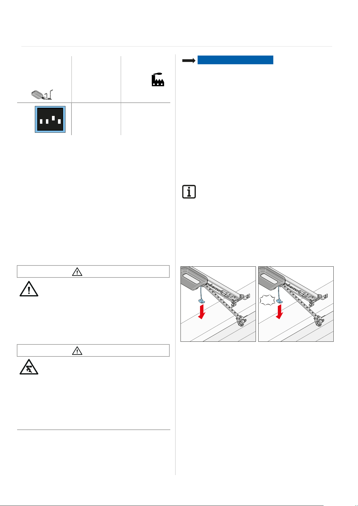
13. Operation
“clic ”
Setting the DIP
switches of
the ceiling
control unit
3
ON
1234
ON OFF
• Continuous
power to the
complete system
activated
• Power-saving
mode activated
13.6 In the event of a power failure
The programmed force values and end positions of the
operator remain saved in the event of a power failure.
After the voltage supply has been restored, the first
movement of the operator after a pulse is always door
OPEN. The door moves the entire way into the door
OPEN end position.
Also follow the instructions for emergency release in
Chapter "11.10 Installing and removing the accumula-
tor" and "13.7 Function of the emergency release".
13.7 Function of the emergency release
In the event of a power failure, the door can be opened
and closed manually from the inside using a mechanical
emergency release. In particular, observe the warnings
below.
NOTE
• The emergency release is only suitable for opening or
closing the door in an emergency. The emergency
release is not suitable for regular opening or closing.
This could cause damage to the operator and door.
The emergency release must only be used in
emergencies such as a power failure.
• During emergency release, the door could open or
close by itself surprisingly quickly due to a broken
spring or incorrect setting of the weight balancing.
Damage to the door system could occur.
• After the operator is locked back in, move the door into
the door OPEN end position. Otherwise the guide idler
will be hit with too much force.
• Objects in the movement area of the door may be
jammed and damaged. Objects must not be in
the range of movement of the door.
INFORMATION
• The function of the emergency release must be
checked, particularly in the door CLOSE end
position and if necessary, also from outside.
Unlocking must be possible.
• It can be locked and released in any door position.
• The emergency release must be easy to operate
in all necessary positions.
1. Disconnect the operator from the mains voltage.
Check it is disconnected from the power supply.
WARNING
Danger for trapped persons!
Persons may be trapped inside the garage.
If trapped persons cannot free themselves,
severe injury or death may result.
` Check the function of the emergency release
at monthly intervals, particularly from inside
in the door CLOSE end position and if necessary, also from outside.
` You must have faults repaired professionally
without delay.
WARNING
Danger due to falling parts of doors!
If the emergency release is actuated, weak or
broken springs may cause the door to close
suddenly and unexpectedly. This may cause
serious or fatal injury.
` The emergency release should be used only
with the door closed.
` Use the emergency release with great caution
if the door is open.
` Keep persons and animals clear of the range
of movement of the door.
Fig. 1 Fig. 2
2. Pull once on the emergency release cord.
The motor carriage is released.
Door can be moved by hand.
3. Pull the emergency release cord once more.
The motor carriage is locked.
The door can only be moved by the operator.
4. Connect the operator to the mains voltage.
Check that the power supply is connected.
5. Give the operator a command.
$IWHUDSRZHUIDLOXUHWKH¿UVWSXOVHRIWKHRSHUDWRU
is always in the door OPEN direction.
The operator must drive completely to the door
OPEN end position.
51

14. Maintenance and care
14.1 Important notes and information
Service the operator regularly as directed below.
This ensures safe operation of your operator and a long
service life. In particular, observe the warnings below.
DANGER
Danger if not observed!
If warnings are not observed, serious injury or
death may result.
` All warnings must be complied with.
Danger due to electric current!
Contact with live parts may result in electric
FXUUHQWÀRZLQJWKURXJKWKHERG\(OHFWULF
shock, burns or death may result.
` All work on electrical components must be
carried out by a trained electrician.
` Before performing work on the operator, includ-
ing the connection of accessories, it must be
disconnected from the power supply.
` If an accumulator is connected, disconnect
it from the control unit.
` Check that the operator is not live.
` Secure the operator against being switched
back on.
WARNING
Danger of falling!
Unsafe or defective ladders may tip and cause
fatal or serious accidents.
` Use only a non-slip, stable ladder.
` Ensure that ladders are safely positioned.
Danger for trapped persons!
Persons may be trapped inside the garage.
If trapped persons cannot free themselves,
severe injury or death may result.
` Check the function of the emergency release
regularly, particularly from inside in the door
CLOSE end position and if necessary, also
from outside.
` You must have faults repaired professionally
without delay.
Danger due to falling parts of doors!
Parts of the door may become detached and
fall. If persons or animals are hit, this may
cause serious injury or death.
` Always keep the moving door in sight.
` Keep all persons and animals away from
the door until it is completely opened or
closed.
Danger of crushing and shearing!
If the door moves and there are persons or
animals in the movement area, crushing and
shearing injuries may be caused by the mechanism and safety edges of the door.
` Only use the operator when you have a direct
view of the door.
` All danger zones must be visible during
the entire door operation.
` Always keep the moving door in sight.
` Keep persons and animals clear of the range
of movement of the door.
` Never put your hand near the door when it
is moving or near moving parts. In particular,
do not reach into the moving push arm.
` Do not reach into the ceiling suspension unit
when the motor carriage is running along
the track.
` Do not drive through the door until it has
opened completely.
` Never stand under the opened door.
Danger due to hot surfaces!
After frequent operation, parts of the motor
carriage or the control unit may become hot.
If the cover is removed and hot parts are
touched, they may cause burns.
` Allow the operator to cool down before
removing the cover.
NOTE
• The motor carriage is supplied with safety low voltage
via the chain and the track. The use of oil or grease will
greatly reduce the conductivity of the chain, track and
motor carriage. This may result in faults due to inadequate electrical contact.
The chain and track are maintenance-free and must
not be oiled or greased.
• The use of unsuitable cleaning agents may damage
the surface of the operator.
Clean the operator with a dry lint-free cloth only.
52
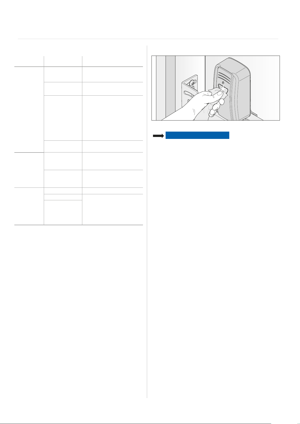
14. Maintenance and care
14.2 Maintenance schedule
How often? What? How?
Once
a month
Once a year
As needed
• Test
the emergency
release
• Test obstacle
detection
• Test
the photocell
• Test obstacle
recognition
• Test the door
and all moving
parts
• Check screws
on door, ceiling
or lintel
• Chain and track • Maintenance-free
• Track • See Chapter "14.3 Care"
• Clean
the housing
of the ceiling
control unit and
motor carriage
• See Chapter
"13.7 Function of the
emergency release"
• See Chapter "12.1 Testing
obstacle detection"
• Interrupt the active photocell
while the door is closing.
The door must stop and
open slightly. If automatic
closing is activated, the door
opens completely.
• If necessary, clean
the photocell,
see Chapter "14.3 Care"
• See Chapter "12.1 Testing
obstacle detection"
• As directed by the door
manufacturer
• Check that screws are tight
and tighten if necessary
Cleaning the photocell
Fig. 1
NOTE
• Do not change the position of the photocell when
cleaning it.
1. Clean the housing and reflectors of the photocell with
a damp, lint-free cloth.
14.3 Care
Clean track, motor carriage and ceiling control
unit
1. Disconnect the operator from the mains voltage.
If an accumulator has been installed, remove
the control unit cover and disconnect the accumulator
from the ceiling control unit, see also Chapter
"11.10 Installing and removing the accumulator".
Then check that the power is disconnected.
2. Remove loose dirt with a moist, lint-free cloth:
ņ from the motor carriage and the ceiling control unit
ņ from the track and the inside of the track
3. If required, install the accumulator in reverse order of
removal.
Re-connect the operator to the mains voltage. Check
the power supply.
The operator is supplied with voltage.
53

15. Troubleshooting
15.1 Important notes and information
Observe the basic warnings listed below.
DANGER
Danger if not observed!
If warnings are not observed, serious injury or
death may result.
` All warnings must be complied with.
Danger due to electric current!
Contact with live parts may result in elec-
WULFFXUUHQWÀRZLQJWKURXJKWKHERG\(OHFWULF
shock, burns, or death may result.
` All work on electrical components must be
carried out by a trained electrician.
` Disconnect the mains plug before working on
the operator.
` If an accumulator is connected, disconnect it
from the control unit.
` Check that the operator is not live.
` Secure the operator against being switched
back on.
WARNING
Danger of falling!
Unsafe or defective ladders may tip and cause
serious or fatal accidents.
` Use only a non-slip, stable ladder.
` Ensure that ladders are safely positioned.
Danger for trapped persons!
Persons may be trapped inside the garage.
If trapped persons cannot free themselves,
severe injury or death may result.
` Check the function of the emergency release
at monthly intervals, particularly from inside
in the door CLOSE end position and if neces-
sary, also from outside.
` You must have faults repaired professionally
without delay.
Danger due to falling parts!
Parts of the door may become detached and
fall. Persons may be hit. Severe injuries or
death may result.
` Always keep the moving door in sight.
` Keep all persons and animals away from
the door until it is completely opened or
closed.
` Do not drive through the door until it has
opened completely.
Danger of entrapment!
Loose clothing or long hair may be trapped by
moving parts of the door.
` Keep clear of the moving door.
` $OZD\VZHDUWLJKW¿WWLQJFORWKLQJ
` Wear a hairnet if you have long hair.
Danger of crushing and shearing!
If the door moves and there are persons or
animals in the movement area, crushing and
shearing injuries may be caused by the mechanism and safety edges of the door.
` Only use the operator when you have a direct
view of the door.
` All danger zones must be visible during
the entire door operation.
` Always keep the moving door in sight.
` Keep persons and animals clear of the range
of movement of the door.
` Never put your hand near the door when it
is moving or near moving parts. In particular,
do not reach into the moving push arm.
` Do not reach into the ceiling suspension unit
when the motor carriage is running along
the track.
` Do not drive through the door until it has
opened completely.
` Never stand under the opened door.
Danger due to optical radiation!
Looking into an LED at short range for an
extended period may cause optical glare.
This may temporarily reduce vision. This may
cause serious or fatal accidents.
` Never look directly into an LED.
Danger due to hot surfaces!
After frequent operation, parts of the motor
carriage or the control unit may become hot.
If the cover is removed and hot parts are
touched, they may cause burns.
` Allow the operator to cool down before
removing the cover.
NOTE
• If the door is not in view and the radio remote control
is actuated, objects in the movement area of the door
may be jammed and damaged. Objects must not be in
the range of movement of the door.
INFORMATION
• The control unit detects a short-circuit between
chain and track and then switches the operator off.
54

15. Troubleshooting
15.2 Preparing for troubleshooting
The following guide to troubleshooting lists potential
problems and their causes and information on correcting
them. In some cases, other chapters and sections with
a more detailed description are referenced. You will be
prompted to call a qualified specialist if this is required.
Work on the electrical system and live parts must be
performed by a trained electrician.
1. Disconnect the operator from the mains voltage.
If an accumulator has been installed, remove
the cover of the control unit and disconnect
the accumulator from the control unit; see Chapter
"7.2 Cover of the ceiling control unit" and Chapter
"11.10 Installing and removing the accumulator".
Then check that the power is disconnected.
2. After working on the operator, if applicable replace
the accumulator in reverse order.
3. Re-connect the operator to the mains voltage. Check
the power supply.
The operator is supplied with mains voltage.
55

15. Troubleshooting
15.3 Time sequences of operator lighting in normal mode and in case of faults
The flash sequences show information on malfunctions for technicians, end customers and telephone support.
In normal mode
Flash sequences Possible cause Corrective action
Normal mode
2SHUDWRUOLJKWLQJÀDVKHVDVZDUQLQJ
light
In the event of faults
Flash sequences Possible cause Corrective action
Requirement
Operator expects a command
for alarm
A process has triggered a fault
Service
A process has triggered a fault
Fault
Operator or parts of the operator faulty
• Programming mode activated
• Pre-warning time activated
• Function for HFL activated
• Interruption of a safety device during
the movement
• Waiting for a conformation during
the position programming movement
of door CLOSE end position
• Photocell or safety device not OK
before movement
• Dead man movement, safety device
not OK
• Motor return from outside
(e.g. due to attempted break-in)
• Service required (service days,
service cycles have been reached)
• Motor temperature is too high
(overheating)
• 3URJUDPPLQJRIGLႈFXOWSRVLWLRQV
in case of reversing with no visible
cause. The complete distance is
traversed from end position to end
position (dead man by radio, under
direct view only)
• Self-test of electronics
• Blockage detection (gear breakage,
Hall sensor fault)
• Limit switch does not operate
(e.g. wire break, limit switch fault)
• Counting pulses sent in the wrong
direction (motor cable was incorrectly
connected)
• Run time exceeded • Movement range too long, movement
• Error during plausibility test of Memo • Have it checked and, if necessary,
• Intrinsically safe wicket door contact
defective
• None, for information
• Remove obstacle
• &RQ¿UPDWLRQRISRVLWLRQSURJUDPPLQJ
run
or
• Sluggish point during programming;
see Chapter "9.3 Carrying out
manual initial operation"
• Check photocell and realign if
necessary
• If necessary, have components
UHSODFHGE\DTXDOL¿HGVSHFLDOLVW
• +DYHLWFKHFNHGE\DTXDOL¿HG
specialist
• For information
• Have the service performed by
DTXDOL¿HGVSHFLDOLVW
• Allow motor to cool
• For information
• Have it checked and, if necessary,
FRPSRQHQWVUHSODFHGE\DTXDOL¿HG
specialist
• Have cable connections checked
E\DTXDOL¿HGVSHFLDOLVWDQG
if necessary, have components
replaced
• Check wiring, correct if necessary
range is restricted to max. 7000 mm
FRPSRQHQWVUHSODFHGE\DTXDOL¿HG
specialist
• Carry out power reset of 20 seconds
• If necessary, have component
replaced
56

15. Troubleshooting
15.4 Troubleshooting table
Problem Possible cause Test/check Remedy
The operator opens
the door when
the transmitter or
command device is
actuated but does not
close it.
Operator cannot
be operated with
the command device.
When a button on
the transmitter is
pressed, the operator
does not open or
close the door.
• Photocell and safety
device interrupted
• Automatic closing
function activated
• No power • Check power supply • Check the power outlet with
• Limit switch on motor
carriage defective
• The operator
was unlocked by
the emergency
release mechanism
• Control device
incorrectly connected
to the operator
• Transmitter defective • Operator cannot be started with
• Operator defective • Operator cannot be started with
• Electrical supply
voltage outside
the approved range
• Transmitter not
programmed
• Battery in
WKHWUDQVPLWWHULVÀDW
• Transmitter defective • LED on transmitter does not light up• Replace transmitter
• Check photocell and safety
devices
• Wait to see whether the operator
starts automatically after
30 seconds
• Unlock operator and push motor
carriage to the centre of the track
• Lock operator
• Actuate transmitter
• If the operator still closes the door
but does not open it, the limit
switch is defective
• Check that the door can be moved
manually
• Check function of operator with
a transmitter
the transmitter
the transmitter or the connected
command device
• Have the mains voltage checked
by a trained electrician
• Radio LED does not light up when
the transmitter is operated
• Remove obstacle
• The photocell must be aligned
• If necessary, have it checked and
UHSODFHGE\DTXDOL¿HGVSHFLDOLVW
• Automatic closing function
deactivated
• Have the cause corrected by
a trained electrician
DGLႇHUHQWGHYLFHIRUH[DPSOH
by plugging in a lamp
• Have the limit switch replaced
E\DTXDOL¿HGVSHFLDOLVW
• Pull the emergency release
handle to lock the operator
• Check wiring and correct
if necessary
• Check transmitter power supply
• If necessary, replace the battery of
the transmitter
• If necessary, replace the transmitter
with a new one
• Have operator repaired or
UHSODFHGE\DTXDOL¿HGVSHFLDOLVW
• Have the cause corrected
by a trained electrician
• Programme transmitter
• Replace the battery of
the transmitter
Radio command
cannot be
programmed.
0(02,GHQWL¿HUHUURU • Incorrect Memo • All four LEDs for radio blink
MEMO device type
error
• Memory full • All four LEDs for radio blink
cyclically for about 3 seconds
cyclically for a short time and
then go out for a long time.
The operator lighting of the motor
carriage blinks 4 times short and
4 times long.
• System error • All four LEDs blink cyclically for
a long time and then go out for
a short time. If voltage is present,
the operator lighting of the motor
carriage blinks an additional four
times.
• Memory full; see Chapter
"10.6 Information on Memo"
and "10.8 Deleting a transmitter
button from the radio channel"
• Disconnect operator from
the power supply, unplug Memo,
re-supply operator with power
• Memo can be deleted via
the Radio button; see Chapter
"10.11 Deleting all radio
channels in the receiver"
57

15. Troubleshooting
Problem Possible cause Test/check Remedy
Operator stops the
door during closing
and opens it partially
or completely.
Operator stops while
the door is opening.
Operator lighting
or the Lumi+
supplemental lighting
does not work
Speed varies while
opening and closing
the door
Motor carriage is
pulled away from limit
stop
• Door has detected
an obstacle
• Photocell was
interrupted
• Photocell defective
or misaligned
• Door has detected
an obstacle
• Operator lighting
defective
• Lumi+ supplemental
lighting defective
• Track dirty • Clean with a moist, lint-free cloth;
• Chain tightened
incorrectly
• Spring tension is too
high, door is opened
too far
• Check whether there are any
obstacles in the movement range
of the door.
• Check LEDs on photocell. • Remove obstacle
• Check whether there are any
obstacles in the movement range
of the door.
• Check the weight balance of
the door – it must run smoothly.
• Check door operation and spring
tension
• Check door OPEN end position
• Remove obstacle
• If necessary, have door
mechanism checked and set
E\DTXDOL¿HGVSHFLDOLVW
• Align photocell
• Check wiring
• If necessary, have defective
photocell replaced
• Remove obstacle
• If necessary, have door
mechanism checked and repaired
E\DTXDOL¿HGVSHFLDOLVW
• Have motor carriage replaced with
DQHZRQHE\DTXDOL¿HGVSHFLDOLVW
• ,IQHFHVVDU\UHWUR¿W/XPL+
supplemental lighting
• Have Lumi+ checked by
DTXDOL¿HGVSHFLDOLVWDQGUHSODFHG
with a new one if necessary
see Chapter "14.3 Care"
• Tighten the chain; see Chapter
"6.3 Installing the drive system"
• Adjust door operation and spring
tension
• Adjust door OPEN end position
• Fit Lock accessory
15.5 Replacing the motor carriage
The instructions for "Disassembling the motor
carriage" can be downloaded from SOMMER at:
www.sommer.eu
If applicable, save the existing settings on the old motor
carriage via SOMlink and a WiFi-enabled device. The
settings can be transferred to the new motor carriage
later.
The new motor carriage is in delivery condition from the
factory. After replacing the motor carriage, make sure that
used accessories have been transferred to the new motor
carriage.
Initial operation must be repeated and the special functions
of the motor carriage reset; see Chapter "9. Initial
operation" and "10. Connections and special functions
of the motor carriage".
58
Handheld transmitters which are used must also be
reprogrammed, see Chapter "10.5 Programming the
transmitter". However, handheld transmitters do not
have to be programmed if the Memo accessory part has
already been used.
After successful initial operation, run a function test and
a final test; see Chapter "12 Function test and final
test".
INFORMATION
• Save the existing settings of the motor carriage
with the help of SOMlink and a WiFi-enabled
device. After the new motor carriage has been
inserted, reinstall the data.

16. Taking out of operation, storage and disassembly
16.1 Important notes and information
Disassembly of the operator may only be performed
by a qualified specialist. In particular, observe
the warnings below.
DANGER
Danger if not observed!
If warnings are not observed, serious injury or
death may result.
` All warnings must be complied with.
Danger due to electric current!
Contact with live parts may result in electric
FXUUHQWÀRZLQJWKURXJKWKHERG\(OHFWULFVKRFN
burns or death will result.
` All disassembly work on electrical components
must be carried out by a trained electrician.
` Disconnect the power plug before
disassembling the operator.
` If an accumulator is connected, disconnect it
from the control unit.
` Check that the operator is not live.
` Secure the operator against being switched
back on.
WARNING
Danger of falling!
Unsafe or defective ladders may tip and cause
serious or fatal accidents.
` Use only a non-slip, stable ladder.
` Ensure that ladders are safely positioned.
Danger of tripping and falling!
Unsafely positioned parts such as packaging,
operator parts or tools may cause trips or falls.
` Keep the disassembly area free of unneces-
sary items.
` Place all parts where no-one is likely to trip or
fall over them.
` The general workplace guidelines must be
observed.
Danger due to hot surfaces!
After frequent operation, parts of the motor
carriage or the control unit may become hot.
If the cover is removed and hot parts are
touched, they may cause burns.
` Allow the operator to cool down before
removing the cover.
Danger due to optical radiation!
Looking into an LED at short range for an
extended period may cause optical glare.
This may temporarily reduce vision. This may
cause serious or fatal accidents.
` Never look directly into an LED.
Risk of eye injury!
&KLSVÀ\LQJZKHQGULOOLQJPD\FDXVHVHULRXV
injuries to eyes and hands.
` Wear safety glasses when drilling.
Risk of injury in the head region!
Impact with suspended objects may cause
serious abrasions and cuts.
` You must wear a safety helmet when
disassembling suspended parts.
CAUTION
Risk of injury to hands!
Rough metal parts may cause abrasions and
cuts when picked up or touched.
` You must wear your personal safety gloves
when working with rough metal parts.
NOTE
• If there is an accumulator in the control unit, it must be
removed by a trained electrician; see Chapter
"11.10 Installing and removing the accumulator".
16.2 Taking out of operation and
disassembly
The operator and its accessories must be disconnected
from the power supply when taking them out of operation
or during disassembly.
1. Pull the power plug out of the power outlet.
If an accumulator has been installed, remove the control unit cover and disconnect the accumulator from
the control unit. See also Chapter "11.10 Installing
and removing the accumulator".
Then check that the power is disconnected.
2. Disassembly is carried out in reverse order of
installation.
16.3 Storage
Store the packaging units as follows:
• in enclosed, dry rooms so that they are protected from
moisture
• at a storage temperature from –25 °C to +65 °C
• secure to prevent falling
• leave room for unhindered passage
NOTE
• Improper storage may damage the operator.
The operator must be stored in closed and dry rooms.
16.4 Disposal of waste
Observe the instructions for disposal of packaging,
components, batteries and, if applicable, the accumulator.
59

16. Taking out of operation, storage and disassembly
WARNING
Danger of hazardous substances!
Improper storage, use or disposal of accumulators, batteries and operator components are
dangerous for the health of humans and animals. Serious injury or death may result.
` Accumulators and batteries must be stored
out of the reach of children and animals.
` Keep accumulators and batteries away from
FKHPLFDOPHFKDQLFDODQGWKHUPDOLQÀXHQFHV
` Do not recharge old accumulators and
batteries.
` Components of the operator as well as old
accumulators and batteries must not be
disposed of with household waste. They must
be disposed of properly.
NOTE
• Dispose of all components in accordance with local and
national regulations to avoid environmental damage.
INFORMATION
• All components that have been taken out of
service, old accumulators and operator batteries
must not be disposed of with household waste.
Dispose of components which are no longer in
use, old accumulators and batteries properly.
You must observe the local and national
regulations.
60

17. Short instructions for installation
The short instructions do not replace the installation and operating manual.
Read this Installation and Operating Manual carefully and, most importantly, observe all safety instructions and
warnings.
This will ensure that you can install the product safely and optimally.
5 mm
10 mm
17 mm
10 mm
13 mm
17 mm
3
4
5
90°
90°
6
1
2
7
90°
90°
8
10 mm 17 mm 17 mm
9
“clic”
“clic”
61

70 mm 70 mm
100-700 mm
10 mm
B
ACK
H
INTEN
10
100-700 mm
11
13 mm
22
23
“clic ”
12
13
X
35 mm
min.
14 15
½½½
16 17
10 mm
½
65 mm
5–65 mm
21 mm
24
25
5 mm
X
26
15
27
30 mm
18
20
min.
15 mm
15 mm
13 mm
19
21
½½½
½
28
X
¹⁄
¹⁄
X
HM
65 mm
13 mm
29
“clic ”
62

< 1100 mm
30
36
31
32
33
RADIO
4
3
2
1
ON
RESET
RADIO
4
3
2
1
ON
RESET
RADIO
4
3
2
1
ON
RESET
37
38
≈2 x
34
35
¹⁄
¹⁄
STATUS
2
1
RESET
rt
sw
STATUS
SENSO
BUZZER
MEMO
63

18. Connection diagrams and functions of the DIP switches for
+-
base/base+
Fig. Connection
diagram, motor carriage
wh
gn
br
8k2
+12 V
OSE
Supply of external accessories
12 V/max.100 mA
GND
Optional
pushbutton
switch
Warning
light
DC 24 V/
max.
25 W
max.
100 mA
24 V/ max. 100 mA (500 mA*)
COM
Signal
GND
DC 24 V
Fig. Connection diagram
ceiling control unit
+
gn
+
rd
-
ChainTrack
GND
AC 24 V
Transformer
AC 220–240 V
L`
AC 220–240 V
LNN`
Mains
connection
external device
* 500 mA are only available if an LED warning light (max. 3 W) or no warning light is
connected
• When connecting external devices, power-saving mode must be deactivated to ensure the power supply.
• The version can vary depending on the type. This means, for example, that the use of accessories can vary.
ON OFF
4
3
2
1
ON
4
3
2
1
ON
4
3
2
1
ON
4
3
2
1
ON
4
3
2
1
ON
• Automatic
closing function
activated
• Partial opening
activated/
lighting function
deactivated
• Automatic
closing function
deactivated
• Partial opening
deactivated/
lighting function
activated
• "Conex" additional
ON
1
23
4
ON
1234
ON
circuit board
• 7GH¿QHVGRRU
OPEN
• 7GH¿QHVGRRU
CLOSE
• Relay is activated
during door
movement and if
the door is not closed*
• Continuous power to
the complete system
activated
1234
• COM and Signal
ON
activated as button
input (partial opening
1234
*e.g.: door status display
ON
OFF
• "Conex" additional
circuit board
• T1 pulse sequence
• T2 lighting
function/partial
opening
• Lighting function
• Power-saving
mode activated
• COM and Signal
activated as
safety contact for
)
photocell
64


SOMMER Antriebs- und Funktechnik GmbH
Hans-Böckler-Straße 21-27
D-73230 Kirchheim/Teck
Germany
+49 (0) 7021 8001-0
+49 (0) 7021 8001-100
info@sommer.eu
www.sommer.eu
© Copyright 2019 All rights reserved
 Loading...