


 Loading...
OPERATION / INSTRUCTION MANUAL
AND
GENERAL INFORMATION
165 Independence Court, Lancaster, PA 17601
Telephone 717-397-5100 Fax 717-291-0877
1-800-23-SOMAT (1-800-237-6628)
www.somatcompany.com
rev 3/09

SAFETY
INSTRUCTIONS
READ THE MANUAL COMPLETELY BEFORE ATTEMPTING TO OPERATE THE UNIT.
HIGH VOLTAGE! DO NOT PERFORM ANY REPAIRS TO MOTORS OR CONTROL SYSTEMS WITHOUT TURNING OFF THE MAIN POWER.
ALWAYS TURN THE MAIN POWER OFF AND LET ALL MOTORS COME TO A STANDSTILL BEFORE DOING ANY MAINTENANCE ADJUSTMENTS OR CLEANING OF THE UNIT.
BEFORE STARTING, BE SURE ALL PERSONNEL ARE CLEAR OF MOVING PARTS.
KNOW LOCATION AND FUNCTIONS OF ALL START/STOP BUTTONS AND SAFETY SWITCHES.
DURING PERIODIC MAINTENANCE, CHECK ALL SAFETY SWITCHES TO BE SURE THEY ARE OPERATING PROPERLY.
DO NOT REMOVE OR ALTER GUARDS.
DO NOT REMOVE SAFETY LABELS. IF LABELS ARE MISSING OR DESTROYED, CONTACT FACTORY FOR REPLACEMENT.
DO NOT OBSTRUCT ELECTRICAL PANELS OR PUSH BUTTONS.
GOOD HOUSEKEEPING IS THE MOST IMPORTANT SAFETY PROCEDURE.

IMPORTANT
The Instruction Manual is important to the proper operation and maintenance of your
SOMAT® System. It should be readily available to those who are responsible for the operation and
performance of the SOMAT® equipment.
For ordering duplicate manuals, please contact:
SERVICE DEPARTMENT
SOMAT COMPANY
165 Independence Court, Lancaster, PA 17601 USA Telephone 717-397-5100, Fax 717-291-0877 1-800-23-SOMAT (1-800-237-6628)
Internet: www.somatcompany.com parts@somatcompany.com
SOMAT COMPANY
LIMITED WARRANTY
SOMAT COMPANY warrants each new product manufactured by it to be free from defects in material and workmanship under normal use and service, which does not include normal wear of parts, ("normal use and service", with respect to Pulpers, Presses, water Hydra-Extractors, Waste Handling and Processing Systems, shall mean the handling only of waste items of the types listed in the SOMAT® Quotation or Sales Order therefore and within the LIMITATIONS THEREIN set forth), its obligation under this warranty being limited to repairing or replacing any part or parts thereof, free of charge INCLUSIVE of labor to remove and replace, f.o.b. factory from which shipped, which shall, within one year from initial start-up of the SOMAT® System or from date of original installation of the product if not a system, or eighteen months from date of shipment, whichever shall first occur, be returned to SOMAT® at the factory from which shipped, with transportation charges prepaid, and which SOMAT's examination shall disclose to its satisfaction to have been thus defective. This warranty shall not apply to any product or part which shall have been repaired or altered by any person not employed or retained by SOMAT®, so as in the judgment of SOMAT® to affect its operation and reliability, nor which has been installed, operated, or maintained contrary to SOMAT® OPERATION or PREVENTIVE MAINTENANCE INSTRUCTION MANUALS or to other written instructions or drawings approved by SOMAT®, nor which has been subject to misuse, negligence, or accident. This warranty shall not apply should the SOMAT® System be initially started up without a duly authorized SOMAT® representative present.
EXCEPT AS HEREIN EXPRESSLY STATED, NO WARRANTY, EXPRESS, IMPLIED OR BY LAW, (INCLUDING BUT NOT LIMITED TO ANY IMPLIED WARRANTY OF MERCHANTABILITY OR FITNESS FOR A PARTICULAR PURPOSE), IS MADE BY SOMAT; AND IN ANY EVENT SOMAT’S LIABILITY, WHETHER IN CONTRACT, TORT, STRICT LIABILITY, OR UNDER ANY WARRANTY, OR OTHERWISE, SHALL NOT EXCEED THE PURCHASE PRICE RECEIVED BY IT AND SHALL IN NO EVENT INCLUDE ANY CONSEQUENTIAL, INCIDENTAL, PUNITIVE OR OTHER SPECIAL DAMAGES.
NO CHANGE IN THIS WARRANTY AND LIMITATION OF LIABILITY AND NO SUBSTITUTE THEREFORE (WHETHER INCORPORATED IN A PURCHASE ORDER OR OTHERWISE) SHALL BE EFFECTIVE UNLESS SPECIFICALLY SET FORTH IN A WRITTEN INSTRUMENT SIGNED BY AN OFFICER OF SOMAT®.
rev. 08/01/00
SYSTEM DESCRIPTION
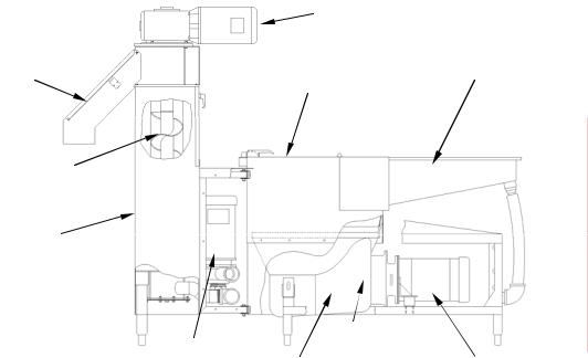
The SOMAT® System prepares solid waste materials for disposal by transforming the materials, mixed with water, into a pulp. This transformation takes place in a unit called a pulper which is designed to reduce all forms of paper, plastic, foil, and food waste to small sizes. The waste material is manually fed to the pulper. The continual flow of water and the rotation of the cutting mechanism create a strong vortex action which pulls the waste against the cutting blades of the impeller. A portion of the resultant slurry passes through a perforated stainless steel ring surrounding the pumping impeller. This ring allows sufficiently small particles to pass through the sizing holes. These particles are carried in the slurry to the extractor where the water is separated and returned to the pulper. Refer to the pulper section for detail views of the cutting mechanism.
Items such as tin cans, silverware, nails, bolts and other non-pulpable objects which may be inadvertently fed into the pulper are separated out by centrifugal force and gravity. These items settle to the bottom of the tank. These items should be emptied manually while wearing gloves during cleanup.
|
Extractor Drive Motor |
|
|
Discharge |
Pulper Lid |
Feed Tray |
|
Chute |
|||
|
|
Screw
Extractor
Return Water |
|
Cutting |
|
|
Pulper |
Mechanism |
Pulper Drive |
||
Pump |
||||
|
||||
Tank |
|
Motor |
||
|
|
SUPER 60 CLOSE-COUPLED SYSTEM
The SOMAT® System is designed to pump the mixture of macerated solids and water, called a slurry, to the extractor where the slurry is reduced to a semi-dry pulp. Within the extractor, the slurry is carried upward by a helical screw within a perforated tubular screen. The water passes through the screen and is pumped back to the pulping unit. The solids continue up the screw to a compression chamber, where additional water is removed. The solids in this area are called the plug. This plug is broken up at the discharge opening by a cutter. The pulp then falls out of the discharge chute in to a waste container. This system is capable of reducing the volume of average non-compacted waste by approximately 80 percent. During the process some water is absorbed by the pulp. Fresh make-up water is supplied to the pulper automatically through a solenoid valve which responds to a PLC.
The system is powered by electric motors with the associated controls housed in the Som-A-Trol enclosure (electric control panel).
In addition to the basic system as discussed to this point, numerous additional items of equipment may or may not be required to comprise a specific system.
OPERATING INSTRUCTIONS
TYPICAL STARTUP AND OPERATING PROCEDURE - The following startup procedures must be followed prior to operating the System:
1. Check to ensure that the main power switch of the SOM-A-TROL® panels is in the "ON" position.
2Push GREEN pushbutton on SOM-A-TROL panel or remote pushbutton station to close drain if opened. If drain is open, you will see a slow GREEN flash to indicate the drain is open. Once pressed, the drain will automatically close and refill the pulper tank.
3.Unlock the Pulper "STOP” button. The Pulper will begin to fill with water, this is indicated by a flashing GREEN light. When the water has reached the prescribed level as indicated by a solid GREEN light, press the Pulper "START" button and wait until there is a continuous flow of return water. Then begin feeding waste to the Pulper either manually or by starting waste down the flushed trough, if so equipped.
Waste Feeding Instructions - Best results are obtained if the Pulper is fed waste at a UNIFORM RATE. Under normal conditions, waste may be fed to the Pulper as long as a strong vortex is maintained in the tank. If waste is fed too fast the vortex will diminish to a point where it will no longer pull the material into the impeller for efficient grinding.
Do not "starve" the Pulper. If no waste is available for disposal, TURN THE PULPER OFF. Don't "slug" the Pulper for short periods of time with excessive feeding. Overloading interferes with the grinding process and takes longer to dispose of a given quantity of waste than if the machine is fed at a UNIFORM RATE.
When shutting down the Pulper for short periods, it is not necessary to run the Pulper until all the waste has been pumped out of the tank. Run the Pulper for a few minutes to thin down the slurry and then shut off the machine.
SHUTDOWN PROCEDURES - The following shutdown procedures must be followed prior to performing necessary cleaning and maintenance duties.
1.Allow the Pulper to operate approximately fifteen minutes after the last waste has been fed.
2.Depress black “TIMED STOP” pushbutton once to engage spray rinse system, system will then time out on its own. The Pulper will stop when the shutdown timer has timed out.
3.Press the "STOP" button and engage the locking attachment. Press “DRAIN EMPTY” pushbutton on panel door to drain system. This pushbutton will DRAIN ONLY, you must press GREEN start button to close drain.
4.Refer to the applicable Pulper and Hydra-Extractor® maintenance sections of this manual for daily, weekly and long term shutdown cleaning procedures and maintenance instructions.

Light Codes:
Newer SOMAT systems employ a micro-computer to control many of the unit functions. If a fault or overload is detected, the system will flash a series of codes by lights located either on the pushbutton station OR on the panel enclosure itself. Below is a list of the most commonly used for Close Coupled machines.
Solid Green: All safeties are latched and secure, system is ready to run
Flashing Green: System is in timed stop mode, extractor will spray, after less than 10 minutes system will shut down.
Slow flashing Green: Unit drain is open, press Green pushbutton to close drain.
Two Green flash, pause, and repeat: All safeties are latched and secure, tank is filling.
Solid Red: One of systems 3 motors is overloaded and must be reset
Flashing Red: Lid switch on pulper or extractor lid is open, shut lid to resume normal operation
Multi-flash Red: See system electrical prints for diagnosis
SPECIAL OPERATING CONDITIONS - While applications vary widely the following conditions could occur and should be watched for:
A.Overfeeding - The SOMAT® Pulper is designed as a continuous process machine. In general, the feed rate should not exceed one tenth of the rated hourly capacity in any six minute period. Exceeding this will cause the machine to bog down and operate under its rated capacity.
B.Foaming - this is caused by contaminants in the water, or by certain materials in the waste, such as
glue in corrugated cardboard. Add a de-foamer, such as Somat® defoamer, or any of a number of commercial preparations.
C.Corrosion - If the water and/or the waste are acidic or alkaline, use a buffering agent to neutralize the water. Regular testing is recommended, since rapid corrosion due to acidic or alkaline conditions can result in costly repairs.
D.Freezing - All equipment and piping should be protected from freezing. Insulation and heating cable are often used where equipment is exposed.
E.Non-Pulpables - The SOMAT® Pulper is designed to handle a limited amount of non-pulpable material. The lighter items are eventually ground and the heavier material is discharged into the junk box.
However, the SOMAT® Pulper is not designed to handle heavy masonry materials or tramp iron and other materials of this nature. Such items will break away the cutting teeth and seriously reduce the machine's ability to handle material of any kind.
OPERATING INSTRUCTIONS
Occasionally, the amounts of non-pulpables may become excessive and, due to their slower processing rate, create a material build-up in the Pulper tank. Safely stop the Pulper, scoop out the non-pulpable matter, and then re-start the Pulper.
F.Wear - Moving parts, and their mating surfaces, will wear with service, especially those which are part of cutting mechanisms. Your routine maintenance and inspection, as described in the applicable component sections, will disclose which parts are wearing and provide an indication as to when replacement will be necessary. The maintenance plan should include pre-ordering of spare parts and scheduled replacement.
G.Rotating blades may be re-sharpened. To remove blades please follow instructions located in the “Cutting Mechanism” section of this manual.

CLEANING INSTRUCTIONS
After feeding waste to the SOMAT® System has been completed for the day, the equipment should be thoroughly cleaned. The cleaning operation requires only a few minutes daily and, if properly done, will keep the machine free of odor and at topoperating efficiency. A regular cleaning program will eliminate costly maintenance and unsatisfactory operation.
CLEANING THE PULPER:
With the system properly shut down, in accordance with the System "Shutdown Procedures", perform the following:
TURN THE MAIN POWER OFF
BEFORE DOING ANY
MAINTENANCE OR CLEANING.
1. Clean the Junk Box of non-pulpable material
CAUTION
THERE MAY BE BROKEN GLASS PRESENT
IN THE PULPER
2.Wash the interior of the Pulper shell with a hose, suitable brush, detergent and deodorant or other cleaning solution. Exercise particular care in cleaning the underside of the upper shell flange.
3.Wipe down the equipment exterior.
4.Leave lid open (if allowed) to let machine air out and reduce odors. Close lid and follow start procedure to refill unit.
CLEANING THE HYDRA-EXTRACTOR®:
1.With high pressure hose, wash down screens and interior walls of Hydra-Extractor® housing. If necessary, a longhandled brush can be used.
B.Long Term Shut Down Procedure - If the Pulper is to remain idle for a relatively long period (four weeks or more), special procedures should be taken to protect the equipment. These procedures are as follows:
1.Perform the daily cleaning procedure, and then circulate a solution of a cleaning and disinfecting agent through the lines to combat bacteria growth and odor.
2.Remove the impeller from the Pulper, (refer to Pulper Maintenance Section). Do not remove the mechanical seal. Using a hose and brush, thoroughly clean the mechanical seal, slurry chamber, and the underside of the impeller.
CLEANING COMPOUNDS
The ideal cleaning compounds available for use with SOMAT® equipment combine four important functions: detergency, disinfection, pH buffering and odor counter action.
In order to help our customers overcome the problem of selecting chemicals for use with their SOMAT® System, we offer the chemicals that we believe will best meet their needs.
We offer:
SOMAT® NEUTRO PLUS (72000)
Designed for use in the SOMAT® System to keep it clean, to deodorize, and to reduce grease build-up. This is an industrial strength product. The surfactants in this detergent/deodorant are bio-degradable.
SOMAT® DEFOAMER (73000)
A neutral, liquid silicone emulsion specifically designed for suppressing and controlling undesirable foam. This is an industrial strength product.
The surfactants in this defoamer are bio-degradable.
Dilution: Five (5) parts water to one (1) part defoamer.
Please direct all orders, whether by mail, phone, fax or email to our SERVICE DEPARTMENT. If you have any questions, please feel free to contact us at this office. Phone- 717-397-5100, Fax-171-291-0878, parts@somatcompany.com

SUPER 60, CLOSE-COUPLED, PULPER / EXTRACTOR
GENERAL DESCRIPTION - PULPER
The Super 60 Pulper represents advancement in pulping technology incorporating a number of features to increase efficiency and reduce operator adjustments. The overall size is smaller requiring less floor space and the height is lower reducing operator fatigue. Some of the revised components include: a one piece cast stainless steel tank, a horizontally mounted single drive motor with a directly coupled cutting / pumping mechanism, replaceable pumping vanes, integral valves and piping, adjustable rate overflow, automatic water level control, motor operated drain valve, vibration isolation system, tubular stainless steel frame, integral junction box, full polished stainless steel shrouding and a removable trough. A cross-section of the Super 60 Pulper identifies these items.
Lid Latch
|
|
Trough |
Extractor Upper |
Shell Vibration |
Top Shroud |
Attachment Support |
Isolating Gasket |
|
Trough
Flushing
Water
Return
Upper Hose
Shell
Lower
Shell 
Drain |
|
Tank |
|
|
|
|
|
|
Pulper Drive |
Junction |
|
Valve |
Vibration |
|
Vibration |
||
|
Motor |
Box |
|||
|
Cutting |
||||
|
Isolator |
Isolator |
|||
|
|
|
|||
|
Mechanism |
|
|
SUPER 60 PULPER, CLOSE-COUPLED, CROSS-SECTION
The one-piece stainless steel tank is connected to the upper shell through a urethane gasket to create the pulping chamber. In addition to sealing the joint between the tank and upper shell, this gasket is part of the vibration isolation system. On the side of the tank is mounted the cutting and pumping mechanism with a single drive motor. This entire assembly consisting of the tank, cutting / pumping mechanism and motor rests on four vibration isolation mounts which are attached to the tubular stainless steel frame. These four mounts and the urethane gasket form the vibration isolation system, which reduces vibration in the trough and noise, transmitted through the trough and the upper shell. The frame is supported on stainless steel legs with threaded adjustable feet. Attached to the upper shell are polished stainless steel covers, which completely shroud the drive motor and piping. These covers are easily removable by unscrewing attaching screws and lifting the covers. The polished stainless steel lower shell covers the tank and frame. It is supported by the frame, attached at the top to the upper shell, and therefore does not add to the transmission of noise.
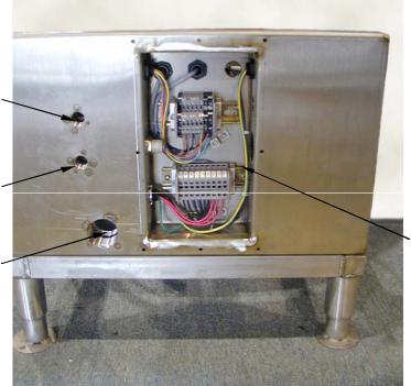
Customer water and electrical connections are made through the end plate, except the drain valve connection at the other end. Note that overflow is the small amount of excess water due to the make-up supply at the solenoid valve, while the return water is the large volume from the extractor return pump that is sent directly into the tank.
Cold Water
Connection
Hot Water |
|
|
Connection |
|
|
Trough or |
Junction |
|
Tray Flush |
||
Box |
||
Water Hose |
||
Connection |
|
SUPER 60 PULPER, CLOSE-COUPLED, END PLATE
The combined action of the rotating blade and the return water inlet to the tank create a swirling action, which aids in the pulping and suspension of material.
Water level is controlled by a PLC which adds fresh water through a solenoid operated valve based on an adjustable timer on the PLC. Overflow is controlled by an adjustable gate valve.
The cutting mechanism is shown in the exploded view. It is driven by a single motor shown at the left side of the assembly. The drive motor, adapter ring and slurry chamber are mounted horizontally and directly to the outside of a tank. The motor drive shaft is fitted with a mechanical seal that prevents the slurry liquid from leaking onto the drive motor or the floor. Between the mechanical seal and the cutting mechanism are the pumping vanes. They are attached to the back of the impeller which is keyed to the drive shaft. The impeller is surrounded by a perforated stainless steel security ring. This ring controls the particle size of the solids entering the slurry chamber. The security ring also holds hardened stationary blades. In front of and attached to the impeller is the hardened stainless steel rotating blade which acts in conjunction with the stationary blades in a scissors action. Also, due to the blade design, it agitates the pulper water as it rotates, improving the slurry suspension and cutting rate. All parts are self aligning during assembly due to the adapter ring and slurry chamber fitting closely with the flange on the motor "C" face and the concentric tolerance of the parts piloting on the motor shaft.

Drive Adapter |
Slurry Chamber |
Motor |
Mechanical Seal |
Seal Ring |
Impeller |
|
Rotating |
|
Pumping |
Security |
Blade |
|
Vanes |
Ring |
|
SUPER 60, CUTTING MECHANISM, EXPLODED VIEW
PERIODIC MAINTENANCE AND INSPECTION
These procedures consist primarily of regularly scheduled cleaning and inspections. The time intervals cited are based on normal use of the SOMAT® unit; approximately six hours per day, seven days per week. Equipment operating more than this or in severe service will require more frequent inspection and maintenance.
Particular attention should be paid to the rotating and stationary blades as these will sustain the highest degree of wear. Continued adherence to these inspections will provide adequate lead time when ordering spare parts, thereby minimizing unnecessary and costly equipment downtime.
WARNING!
TURN THE MAIN POWER OFF AND LOCKOUT BEFORE
DOING ANY MAINTENANCE OR
CLEANING.
PERIODIC MAINTENANCE AND INSPECTION
These procedures consist primarily of regularly scheduled cleaning and inspections. The time intervals cited are based on normal use of the SOMAT® unit; approximately six hours per day, seven days per week. Equipment operating more than this or in severe service will require more frequent inspection/maintenance.
Particular attention should be paid to cutting blades and grinding teeth as these will sustain the highest degree of wear. Continued adherence to these inspections will provide adequate lead time when ordering spare parts, thereby minimizing unnecessary and costly equipment downtime.
PREVENTIVE MAINTENANCE INSPECTION SCHEDULE
|
|
|
DAILY |
WEEKLY |
MONTHLY |
QUARTERLY |
|
|
|
|
|
||
1. GENERAL |
|
|
|
|
||
|
|
|
|
|
|
|
|
a. |
Check shell and slurry chamber |
|
|
|
|
|
|
for wear. |
|
|
X |
|
|
|
|
|
|
|
|
|
b. |
Check exterior finish for |
|
|
X |
|
|
|
corrosion. |
|
|
|
|
|
|
|
|
|
|
|
2. |
IMPELLERS |
|
|
|
|
|
|
|
|
|
|
|
|
|
a. |
Check impeller blades for wear. |
|
X |
|
|
|
|
|
|
|
|
|
|
b. |
Check stationary blades for |
|
X |
|
|
|
|
wear. |
|
|
|
|
|
|
|
|
|
|
|
|
c. |
Check impeller teeth for wear. |
|
X |
|
|
|
|
|
|
|
|
|
|
d. |
Check security ring for wear. |
|
X |
|
|
|
|
|
|
|
|
|
3. |
DRIVE |
|
|
|
|
|
|
|
|
|
|
|
|
|
a. |
Check seal for leakage. |
X |
|
|
|
|
|
|
|
|
|
|
|
b. |
Check bearings for noise and |
|
|
|
X |
|
|
wear. |
|
|
|
|
|
|
|
|
|
|
|

Notes for the Maintenance Procedures listed above.
1.While the tank is filling, open the pulper lid. The machine should stop. Close the pulper lid and lift the extractor chute lid. Again the machine should stop. If the machine continues to fill with either lid open, replace the appropriate proximity switch.
2.Check for a constant flow from the overflow fitting.
3.Look for nicks in the inside leading edges. Grind the inside leading edge of the rotating blade if required as shown below. Do not grind the outer surface. See photo below.
4.Remove covers. Look for water under the spacer ring (between the motor and tank).
5.Lock-out the electrical power at the breaker panel. Rotate the motor with a gloved hand for a few turns. Keep your fingers in contact with the rotating blade to feel for a roughness in the bearings. Listen for a rumble also.
6.Using a hand operated grease gun, slowly dispense approximately a teaspoon (one squeeze of the handle), of one of the following greases into each bearing: Exxon Mobil Polyrex EM, Texaco Polystar, Rykon Premium #2, Pennzoil Pen 2 Lube, Chevron SRI.
7.Remove oil fill plug and check level. Fill, if necessary, to the bottom of the plug hole. Use Amoco American Worm Gear Oil or Mobil Gear Oil #629.
8.Using a hand operated grease gun, slowly dispense approximately a teaspoon (one squeeze of the handle) of water repellant grease.
Rotating Blade
Grind leading edge only
Do not grind this surface
SUPER 60 PULPER, ROTATNG BLADE SHARPENING METHOD
Loading...