

Snorkel S3219E User Manual
Serial number 000000 and after
OPERATOR’S
MANUAL
Part Number 1500834
July 2014

The aerial platform is not electrically insulated. Death or serious injury will result from contact
with, or inadequate clearance from, an energized conductor.
Do not go closer than the minimum safe approach distance as dened by the Minimum Safe
Approach Distance section in Chapter 3–Safety.
Regard all conductors as energized.
Allow for electrical wire sag and aerial platform sway.
If the platform, scissors structure, or any part of the aerial platform contacts a high-voltage electrical
conductor, the entire machine can become electrically charged.
If that happens, remain on the machine and do not contact any other structure or object. This includes
the ground, adjacent buildings, poles, and any other objects that are not part of the aerial platform.
Such contact could make your body a conductor to the other object, creating an electrical shock hazard
resulting in death or serious injury.
If an aerial platform is in contact with an energized conductor the platform operator must warn ground
personnel in the vicinity to stay away. Their bodies can conduct electricity creating an electrical shock
hazard resulting in death or serious injury.
Do not approach or leave the aerial platform until the electricity has been turned off.
Do not attempt to operate the lower controls when the platform, scissors structure, or any part of the
aerial platform is in contact with a high-voltage electrical conductor or if there is an immediate danger
of such contact.
Personnel on or near an aerial platform must be continuously aware of electrical hazards, recognizing
that death or serious injury can result from contact with an energized conductor.
California
Proposition 65 Warning
Battery posts, terminals, and related accessories contain
lead and lead components, chemicals known to the
State of California to cause cancer and birth defects or
other reproductive harm. Wash hands after handling.

Table of Contents
Electrical Danger .............................. inside front cover
Proposition 65 Warning .................... inside front cover
Chapter 1 – Introduction
Aerial Platform Features .............................................1
Options .......................................................................1
Operator’s Manual ......................................................1
Safety Alerts ...............................................................1
Operation ....................................................................1
Maintenance ...............................................................2
Manual of Responsibilities ..........................................2
Additional Information .................................................2
Chapter 2 – Specications
Component Identication ............................................3
General Specications – S3219E ...............................4
Aerial Platform .........................................................4
Platform ...................................................................4
Function Speed .......................................................4
Drive System ...........................................................4
Drive/Lift Level Sensor Interlock .............................4
Tires ........................................................................4
Electrical System .....................................................4
Hydraulic System ....................................................4
Ambient Air Temperature Operating Range ............4
Maximum Wind Speed ............................................4
Chapter 5 – Gauges and Displays
Battery Charge Indicator ..........................................13
Battery Condition Indicator .......................................13
Diagnostic Center Display ........................................13
Chapter 6 – Batteries
General Maintenance ...............................................15
Charging ...................................................................15
Chapter 7 – Controls
Battery Disconnect ...................................................17
Lower Controls .........................................................17
Emergency Stop Button ........................................17
Control Selector/Ground Operation Switch ...........17
Platform Raise/Lower Switch ................................17
Upper Controls .........................................................18
Emergency Stop Button ........................................18
Drive/Lift Selector Switch ......................................18
Joystick .................................................................18
Interlock Switch .....................................................19
Steer Switch ..........................................................19
Drive Range Switch – S4732E ..............................19
Horn Button ...........................................................19
Battery Condition Indicator ....................................19
Circuit Breaker Reset Button ....................................19
Chapter 8 – Prestart Inspection
Chapter 3 – Safety
Electrocution Hazards ................................................5
Minimum Safe Approach Distance .............................5
Prestart Inspection......................................................6
Work Place Inspection and Practices .........................6
Operation ....................................................................6
Tip-Over and Falling Hazards .....................................6
Electrical System ........................................................7
Hydraulic System........................................................7
Placards and Decals...................................................7
Chapter 4 – Safety Devices
Emergency Stop Controls...........................................9
Control Select/Ground Operation Switch....................9
Upper Control Interlock Switch ...................................9
Drive Motion Alarm ...................................................10
Pothole Protector Skids ............................................10
Drive/Lift Pothole Protector Interlock ........................10
Drive/Lift Level Sensor Interlock ...............................10
Lowering Alarm .........................................................10
Emergency Lowering Lever ......................................10
Safety Prop ............................................................... 11
Guardrails ................................................................. 11
Ground Fault Circuit Interrupter ................................ 11
Tilt Alarm ................................................................... 11
Horn .......................................................................... 11
Flashing Light ........................................................... 11
S3219E/S4732E – 1500834
Operator’s Manual ....................................................21
Electrical System ......................................................21
Battery Fluid Level ................................................21
Battery Terminals ...................................................22
Battery Charger .....................................................22
Safety Prop ...............................................................22
Cables and Wiring Harness ......................................23
Hydraulic System......................................................23
Fluid Level .............................................................23
Hoses, Tubes, and Fittings ....................................23
Free-Wheeling Valve ............................................. 23
Diagnostic Center Display ........................................24
Tires and Wheels ......................................................24
Ground Strap ............................................................24
Lower Control Station ...............................................24
Operating Controls ................................................24
Emergency Stop .................................................... 25
Lowering Alarm .....................................................25
Pothole Protector Interlock ....................................25
Emergency Lowering System ...................................26
Structures .................................................................26
Weldments ............................................................26
Rollers and Slide Blocks .......................................26
Fasteners ..............................................................27
Upper Control Station ...............................................27
Guardrail System ..................................................27
Platform Extension ................................................27
Operating Controls ................................................28
Emergency Stop .................................................... 29
Horn Button ...........................................................29
Lowering Alarm .....................................................29
Drive Alarm ............................................................29

Table of Contents
Electrical Power Outlet .............................................29
Flashing Light ...........................................................29
Placards and Decals.................................................30
Prestart Inspection Checklist ....................................33
Chapter 9 – Operation
Preparing for Operation ............................................35
Lower Controls .........................................................35
Upper Controls .........................................................35
Platform ....................................................................36
Raising and Lowering ............................................ 36
Extending ..............................................................36
Driving and Steering .................................................37
Drive Range Switch – S4732E ..............................37
Drive Speeds ........................................................ 38
Drive/Lift Level Sensor Interlock ...........................38
Swing-Out Trays .......................................................38
Electrical Power Outlet .............................................39
Chapter 10 – Stowing and Transporting
Stowing .....................................................................41
Transporting .............................................................41
Lifting With a Forklift .............................................. 41
Winching ...............................................................42
Driving ...................................................................42
Hoisting .................................................................43
Securing for Transport ...........................................44
Chapter 11 – Emergency Operation
Emergency Lowering ................................................45
Towing ......................................................................45
Chapter 12 – Troubleshooting
Troubleshooting Chart ..............................................47
Appendix A – Glossary
Limited Warranty
S3219E/S4732E – 1500834

Chapter 1 – Introduction
Aerial Platform Features
The aerial platform is a self-propelled scissors lift that has
been designed to raise personnel, their tools, and material
to the workstation. The aerial platform has been designed
for use on hard surface oors such as concrete.
The S3219E uses a single hydraulic cylinder to raise
and lower the platform. The S4732E machines have
two hydraulic cylinders to raise and lower the platform. A
hydraulic motor on each of the front drive wheels provides
power to move the aerial platform.
The standard machine includes the following features:
Proportional drive and lift up control
Driveable at full height
Two speed drive – S4732E
Drive motion alarm
Non-marking tires
Automatic pothole protection system
Level sensor with drive/lift interlock
Diagnostic Center Display
Battery condition indicator
Manual lowering valve
Lockable battery disconnect switch
Tie-down/lifting lugs
Heavy duty battery charger
Swing-out hydraulic component and battery trays
Non-slip metal platform oor
Three foot platform extension
125 volt AC electrical outlet with GFCI
Scissor arm safety support prop
Lowering alarm
Horn
Forklift loadable from three sides
Rear forklift pockets
Saloon style entry doors
Five year limited warranty
The aerial platform has been manufactured to conform to all
applicable requirements of the following organizations.
Occupational Safety and Health Administration
(OSHA)
American National Standards Institute (ANSI)
Canadian Standards Association (CSA)
Options
The following options may be provided on the machine:
Flashing light
Operator’s Manual
This manual provides information for safe and proper
operation of the aerial platform. Some information in this
manual refers to options that may or may not be on your
machine. Read and understand the information in this
Operator’s Manual before operating the aerial platform
on the job.
Additional copies of this manual may be ordered from
Snorkel. Supply the model and manual part number from
the front cover to assure that the correct manual will be
supplied.
All information in this manual is based on the latest
product information at the time of publication. Snorkel
reserves the right to make product changes at any time
without obligation.
Safety Alerts
A safety alert symbol is used throughout this manual to
indicate danger, warning, and caution instructions. Follow
these instructions to reduce the likelihood of personal
injury and property damage. The terms danger, warning,
and caution indicate varying degrees of personal injury
or property damage that can result if the instruction is
not followed.
Danger
Indicates an imminently hazardous situation which,
if not avoided, will result in death or serious injury.
This signal word is to be used in the most extreme
situations.
Warning
Indicates a potentially hazardous situation which, if
not avoided, could result in death or serious injury.
Caution
Indicates a potentially hazardous situation which, if
not avoided, may result in minor or moderate injury. It
may also be used to alert against unsafe practices.
Notes
Notes are used to provide special information or helpful
hints to assist in aerial platform operation, but do not
indicate a hazardous situation.
Operation
The aerial platform has built-in safety features and has
been factory tested for compliance with Snorkel specications and industry standards. However, any personnel
lifting aerial platform can be potentially dangerous in the
hands of untrained or careless operators.
Warning
The potential for an accident increases when the
aerial platform is operated by personnel who are not
trained and authorized. Death or serious injury could
result from such accidents. Read and understand the
information in this manual and on the placards and
decals on the machine before operating the aerial
platform on the job.
S3219E/S4732E – 1500834 1

Chapter 1 – Introduction
Training is essential and must be performed by a quali-
ed person.
Become procient in knowledge and actual operation
before using the aerial platform on the job.
The operator must be trained and authorized to per-
form any functions of the aerial platform.
Operation of the aerial platform must be within the
scope of the machine specications.
The operator bears ultimate responsibility for following
all manufacturer’s instructions and warnings, regulations
and safety rules of their employer and/or any state or
federal law.
Maintenance
Every person who maintains, inspects, tests, or repairs
the aerial platform must be qualied to do so. Following
the daily prestart inspection in this Operator’s Manual will
help keep the aerial platform in optimum working condition. Other maintenance functions must be performed
by maintenance personnel who are qualied to work on
the aerial platform.
Caution
Welding current can be very intense. Damage to
electronic components may result. Connect the
ground clamp as close as possible to the area being
welded. Disconnect battery cables and any microprocessors and control modules before welding on
the machine.
Manual of Responsibilities
All owners and users of the aerial platform must read,
understand, and comply with all applicable regulations.
Ultimate compliance to OSHA regulations is the responsibility of the user and their employer.
ANSI publications clearly identify the responsibilities of all
personnel who may be involved with the aerial platform.
A reprint of the “Manual of Responsibilities for Dealers,
Owners, Users, Operators, Lessors and Lessees of
ANSI/SIA A92.6-2006 Self-Propelled Elevating Work
Platforms” is available from Snorkel dealers or from the
factory upon request.
Copies are also available from:
Scaffold Industry Association, Inc.
P. O. Box 20574
Phoenix, AZ 85036-0574 USA
Additional Information
For additional information contact your local dealer or
Snorkel at:
Snorkel International
P.O. Box 1160
St. Joseph, MO 64502-1160 USA
1-800-255-0317
http://www.snorkellifts.com
If it becomes necessary to weld aerial platform components as a method of repair, take all precautions to
prevent damage to electronic circuitry and devices on
the machine. This includes, but may not be limited to,
disconnecting battery cables and electronic devices.
Do not modify this aerial platform without prior written con-
sent of the Snorkel Engineering Department. Modication
may void the warranty, adversely affect stability, or affect
the operational characteristics of the aerial platform.
2 S3219E/S4732E – 1500834

Component Identication
Chapter 2 – Specications
Entry
Step
Groundstrap
Freewheeling Valve/Brake Release Valve
Hand Pump/Diagnostic Display
Platform
Toeboards
Control Valve Tray
Right Side
Platform Extension
Battery Tray
Emergency
Lowering Lever
Serial
Number
Drive and Steer
Wheels
Tie-Down/Lifting Lugs
Front
Scissors
Structure
Chassis
Upper
Controls
Battery Tray
Electrical
Power Outlet
Hydraulic Tray
Pump/Reservior/Fluid Filter
Left Side
Guardrails
Pothole
Protector Skid
Entry
Doors
Tie-Down/Lifting
Lugs
Power to Platform
Operator’s
Manual
Receptacle
Controls
Lower
Battery Charger
LED Charge Indicators
Rear
Forklift
Pockets
Battery
Charger
Receptacle
S3219E/S4732E – 1500834 3

Chapter 2 – Specications
General Specications – S3219E
Aerial Platform
Working height 25′ (7.6 m)
Maximum platform height 19′ (5.8 m)
Turning radius
Inside 4″ (10.16 cm)
Outside 64.25″ (1.63 m)
Wheelbase 52″ (1.32 m)
Ground clearance
Pothole protector raised 2.63″ (6.68 cm)
Pothole protector lowered 0.75″ (1.9 cm)
Maximum wheel load 1,416 lbs (642 kg)
Maximum ground pressure 175 psi (12.3 kg/cm²)
Weight, EVW
Approximate 2,750 lbs (1,247 kg)
Stowed width 32″ (81.3 cm)
Stowed length 70″ (1.78 m)
With step removed 68.25″ (1.73 m)
Stowed height 79″ (2.0 m)
Platform
Dimensions
Main 28″ x 60.6″ (71.1 cm x 153.9 cm)
Extension 24″ x 47″ (61 cm x 119.4 cm)
Total length with extension 98.75″ (250.8 cm)
Guardrail height 39″ (99 cm)
Toeboard height 6″ (15.2 cm)
Rated work load
Total 550 lb (250 kg)
Extension 250 lb (113 kg)
Maximum number of occupants 1 outdoors
2 indoors
Function Speed
Platform raise 12 to 20 seconds
Platform lower 20 to 26 seconds
High Drive
Platform lower than 6′ (1.8 m)
0 to 2 mph (0 to 3.2 km/h)
Low Drive
Platform higher than 6′ (1.8 m)
0 to 0.4 mph (0 to 0.6 km/h)
Drive System
Standard Two-wheel drive
Gradeability 25%
Maximum drive height 19′ (5.8 m)
Drive/Lift Level Sensor Interlock
Side-to-side 1.5 degrees
Front-to-rear 4 degrees
Tires
Nonmarking solid rubber 12″ x 4″ (30.5 cm x 10.2 cm)
Electrical System
Voltage 24 V DC negative chassis ground
Source Four - 6 V 220 amp hour batteries
Fluid recommended distilled water
Charger 25 amp
Hydraulic System
Maximum pressure 3,000 psi (20,684 kPa)
Reservoir capacity 3 US gal (11.35 l)
System capacity 3.5 US gal (13.2 l)
Maximum operating temperature 160°F (71°C)
Hydraulic uid recommended
Above 10°F (-12°C) ISO VG32 (Mobil DTE-13M)
Below 10°F (-12°C) ISO VG15 (Mobil DTE-11M)
Ambient Air Temperature Operating Range
Fahrenheit 0°F to 110°F
Celsius -18°C to 43°C
Maximum Wind Speed
Gust or steady 28 mph (12.5 m/s)
4 S3219E/S4732E – 1500834
Chapter 3 – Safety
Figure 3 – Minimum Safe Approach Distance
Voltage Range
(Phase to Phase)
Minimum Safe Approach Distance
Feet Meters
0 to 300V Avoid Contact
Over 300V to 50kV 10 3.05
Over 50kV to 200kV 15 4.60
Over 200kV to 350Kv 20 6.10
Over 350kV to 500kV 25 7.62
Over 500kV to 750kV 35 10.67
Over 750kV to 1000kV 45 13.72
D enotes
pro hib ited
zon e
Knowledge of the information in this manual, and proper
training, provide a basis for safely operating the aerial platform. Know the location of all controls and how they operate to act quickly and responsibly in an emergency.
Safety devices reduce the likelihood of an accident.
Never disable, modify, or ignore any safety device.
Safety alerts in this manual indicate situations where
accidents may occur.
If any malfunction, hazard or potentially unsafe condition
relating to capacity, intended use, or safe operation is suspected, stop aerial platform operation and seek assistance.
The operator bears ultimate responsibility for following
all manufacturer’s instructions and warnings, regulations
and safety rules of their employer and/or any state or
federal law.
Electrocution Hazards
The aerial platform is made of metal components and is
not insulated. Regard all conductors as energized. Do
not operate outside during a thunderstorm.
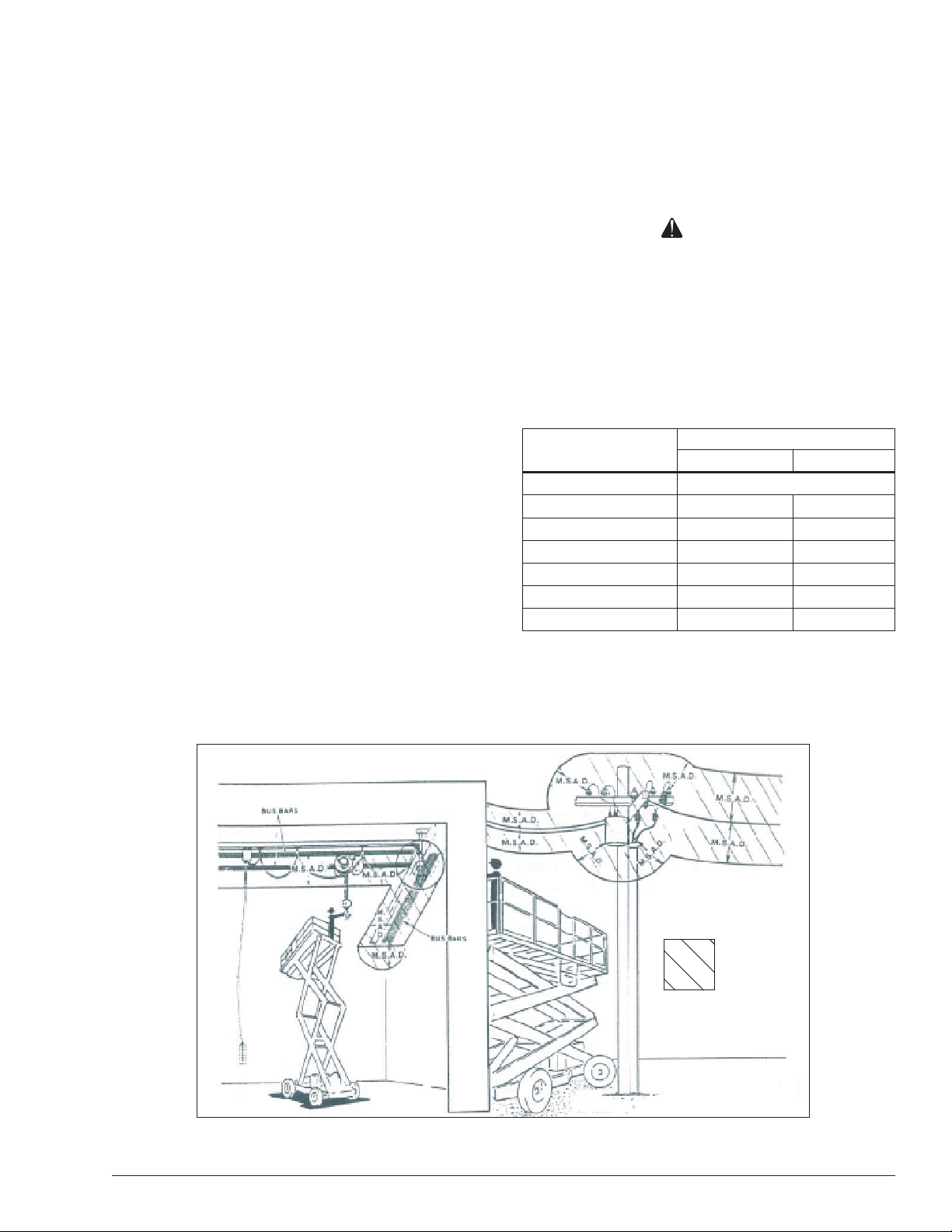
Minimum Safe Approach Distance
Minimum safe approach distances to energized power
lines and their associated parts must be observed while
operating the aerial platform.
Danger
The aerial platform is not electrically insulated. Death
or serious injury will result from contact with, or
inadequate clearance from, an energized conductor.
Do not go closer than the minimum safe approach
distance as dened by ANSI.
ANSI publications dene minimum distances that must
be observed when working near bus bars and energized
power lines. Table 1 and Figure 3 are reprinted courtesy
of Scaffold Industry Association, ANSI/SIA A92.6.
S3219E/S4732E – 1500834 5
Table 1 – Minimum Safe Approach Distance

Chapter 3 – Safety
Prestart Inspection
Perform a prestart inspection before each shift as described in Chapter 8. Do not use the aerial platform on
the job unless you are trained and authorized to do so.
Work Place Inspection and Practices
Do not use the aerial platform as a ground connection
when welding.
The welding ground clamp must be attached to the
same structure that is being welded.
Electrical current ow can be very intense, causing
serious internal damage to some components.
Inspect the area before and during aerial platform use.
The following are some potential hazards that may be in
the work place:
Debris
Slopes
Drop-offs or holes
Bumps and oor obstructions
Overhead obstructions
Unauthorized persons
High voltage conductors
Wind and weather conditions
Inadequate surface and support to withstand load
forces applied by the aerial platform in all operating
congurations
Before using the aerial platform in any hazardous (clas-
sied) location, make certain it is approved and of the
type required by ANSI/NFPA 505 for use in that particular
location.
Know and understand the job site trafc-ow patterns and
obey the agmen, road signs and signals.
to stop movement to avoid contact with structures
or other hazards.
Always look in the direction of movement.
Drive with care and at speeds compatible with the
work place conditions.
Use caution when driving over rough ground, on
slopes and when turning.
Do not engage in any form of horseplay or permit rid-
ers any place other than in the platform.
Secure all accessories, containers, tools and other materials in the platform to prevent them from accidentally
falling or being kicked off the platform. Remove all objects
that do not belong in or on the aerial platform.
Never steady the platform by positioning it against another platform.
Warning
The potential for an accident increases when operating an aerial platform that is damaged or malfunctioning. Death or serious injury could result from such
accidents. Do not operate the aerial platform if it is
damaged or malfunctioning.
Do not operate the aerial platform if it is damaged or not
functioning properly. Qualied maintenance personnel
must correct the problem before putting the aerial platform
back into service.
Operation
Use three points of support when entering or exiting the
platform. For example, use two hands and one foot when
climbing into the platform.
While operating the aerial platform, a good safety prac-
tice is to have qualied personnel in the immediate work
area to:
Help in case of an emergency
Operate emergency controls as required
Watch for loss of control by platform operator
Warn the operator of any obstructions or hazards that
may not be obvious to them
Watch for soft terrain, sloping surfaces, drop-offs, etc.
where stability could be jeopardized
Watch for bystanders and never allow anyone to be
under, or to reach through the scissors structure while
operating the aerial platform
Make sure the area below the platform is free of personnel before lowering.
Keep both feet positioned rmly on the platform oor.
Operate the controls slowly and deliberately to avoid
jerky and erratic operation.
Always stop the controls in neutral before going in the
opposite direction.
Do not dismount while the aerial platform is in motion or
jump off the platform.
Properly stow the aerial platform and secure it against
unauthorized operation at the end of each work day,
Danger
before transporting, or if it is left unattended.
Pinch points may exist between moving components.
Death or serious injury will result from becoming
trapped between components, buildings, structures,
or other obstacles. Make sure there is sufcient
clearance around the machine before moving the
chassis or platform. Allow sufcient room and time
6 S3219E/S4732E – 1500834
Tip-Over and Falling Hazards
Operate the aerial platform only on a rm, at, level
surface capable of withstanding all load forces imposed
by the aerial platform in all operating conditions. Refer
to the General Specications chart for the maximum

Chapter 3 – Safety
wheel load and drive/lift level sensor interlock information. Raise the platform only when the aerial platform is
on level ground.
Danger
The aerial platform can tip over if it becomes unstable.
Death or serious injury will result from a tip-over accident. Do not drive or position the aerial platform
for elevated use near any drop-off, hole, slope, soft
or uneven ground, or other tip-over hazard. Do not
raise the platform outdoors in wind speeds above 28
mph (12.5 m/s).
Do not operate the aerial platform within 4′ (1.2 m) of any
drop-off or hole.
Do not raise the platform in winds above 28 mph (12.5
m/s). Do not add anything to the aerial platform that will
increase the wind loading such as billboards, banners,
ags, etc.
Never operate the aerial platform without all parts of the
guardrail system in place and the entry doors closed.
Make sure that all protective guards, cowlings, and doors
are securely fastened.
Do not exceed the platform capacity nor the platformextension capacity as indicated on the platform rating
placard on the platform. Do not carry loads that extend
beyond the platform guardrails without prior written consent from Snorkel.
1. If you are using a fall restraint, transfer your anchorage from one structure to the other before stepping
across.
2. Remember that you might be transferring to a structure where personal fall arrest is required.
3. Use the platform entrance, do not climb over or
through the guardrails.
Electrical System
Charge the batteries in a well-ventilated area free of
ame, sparks, or other hazards that might cause re or
explosion.
Do not operate any of the aerial platform functions while
the battery charger is plugged in.
Warning
Batteries give off hydrogen and oxygen that can combine explosively. Death or serious injury could result
from a chemical explosion. Do not smoke or permit
open ames or sparks when checking the batteries.
Battery acid can damage the skin and eyes. Serious
infection or reaction could result if medical treatment
is not given immediately. Wear face and eye protection when working near the batteries.
Batteries contain sulfuric acid that can damage your
eyes or skin on contact.
Do not operate the aerial platform from trucks, trailers, rail-
way cars, oating vessels, scaffolds, or similar equipment
unless the application is approved in writing by Snorkel.
Do not use the aerial platform as a crane, hoist, jack or
for any purpose other than to position personnel, tools,
and materials.
Do not climb on the guardrails or use ladders, planks,
or other devices to extend or increase the work position
from the platform.
Take care to prevent rope, electrical cords, and hoses,
etc., from becoming caught in or on the aerial platform.
If the platform or scissors structure becomes caught
on an adjacent structure or other obstacle and is
prevented from normal motion, reverse the control to
free the platform.
If control reversal does not free the platform, evacuate
the platform before attempting to free it.
It is best not to transfer from the platform to another
structure or from the structure to the platform, unless
that is the safest way to do the job. Judge each situation
separately taking the work environment into account. If
it is necessary to transfer from the platform to another
structure the following guidelines apply:
Wear a face shield, rubber gloves, and protective
clothing when working around batteries.
If acid contacts your eyes, ush immediately with clear
water and get medical attention.
If acid contacts your skin, wash off immediately with
clear water.
Hydraulic System
The hydraulic system contains hoses with hydraulic uid
under pressure.
Danger
Hydraulic uid escaping under pressure can have
enough force to inject uid into the esh. Serious
infection or reaction will result if medical treatment is
not given immediately. In case of injury by escaping
hydraulic uid, seek medical attention at once.
Do not place your hand or any part of your body in front
of escaping hydraulic uid. Use a piece of cardboard or
wood to search for hydraulic leaks.
Placards and Decals
The aerial platform is equipped with placards and decals
that provide instruction for operation and accident prevention. Do not operate the aerial platform if any placards or
decals are missing, damaged, or illegible.
S3219E/S4732E – 1500834 7

Chapter 3 – Safety
8 S3219E/S4732E – 1500834
Chapter 4 – Safety Devices
15 0 04 3815 0 04 38
This aerial work platform is manufactured with safety
devices, placards, and decals to reduce the likelihood
of an accident.
For the safety of all personnel, do not disable, modify,
or ignore any safety device.
Safety devices are included in the daily prestart
inspection.
Warning
The potential for an accident increases when safety
devices do not function properly. Death or serious
injury could result from such accidents. Do not alter,
disable, or override any safety device.
Emergency
Stop Button
Figure 4.2 – Upper Control Panel Front
If any safety devices are defective, remove the aerial
platform from service until qualied maintenance personnel can make repairs.
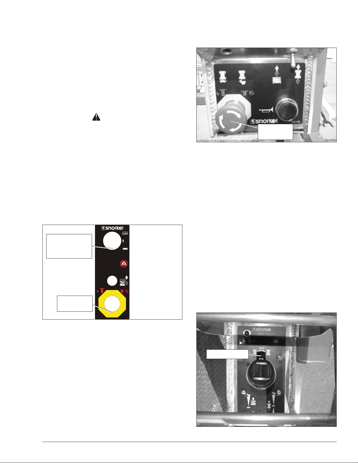
Emergency Stop Controls
There is an emergency stop control at the lower and
upper controls.
At the lower controls, the emergency stop is a two-position red push button (refer to Figure 4.1).
Control
Select/Ground
Operation Switch
Emergency
Stop Button
Figure 4.1 – Lower Controls
Push the emergency stop button inward to disconnect
power to the upper control circuits.
Pull the button outward to restore power.
Control Select/Ground Operation Switch
The control select/ground operation switch (refer to
Figure 4.1) prevents platform movement if the platform
raise/lower switch on the lower control panel is accidently
moved.
Hold the switch downward continually in the lower control
position to enable the platform raise/lower switch functions.
Upper Control Interlock Switch
The interlock switch (refer to Figure 4.3) prevents platform
movement if the joystick on the upper control panel is
accidently moved.
Engage the interlock by grasping the joystick and pulling the switch toward the handle to activate the steering,
drive, or lift functions.
Push the emergency stop button inward to disconnect
power to all control circuits.
Pull the button outward to restore power.
Interlock Switch
Note
The lower controls override the upper controls. If the upper control emergency stop button is engaged, the lower
controls can still be used to operate the aerial platform.
At the upper controls, the emergency stop is a two-position red push button (refer to Figure 4.2).
Figure 4.3 – Upper Control Panel Top
S3219E/S4732E – 1500834 9
Chapter 4 – Safety Devices
Drive Motion Alarm
When the joystick is moved out of neutral to drive the
aerial platform, the alarm emits a loud beeping sound to
warn personnel in the work area to stand clear.
Pothole Protector Skids
The pothole protector skids automatically lower when the
platform is elevated approximately 24″ (61 cm). Ground
clearance is reduced from 2.63″ (6 cm) to 3/4″ (1.9 cm)
when the skids lock into position (refer to Figure 4.4).
Pothole Protector Skids
Figure 4.4 – Pothole Protector Skids
Danger
The aerial platform can tip over if it becomes unstable.
Death or serious injury will result from a tip-over accident. Do not drive or position the aerial platform for
elevated use within 4′ (1.2 m) of any drop-off, hole, or
other tip-over hazard.
interlock operates when the platform is elevated approximately 6′ (1.8 m).
If the chassis is tilted more than one and a half degrees sideto-side or more than four degrees front-to-rear, the drive and
lift functions will not operate and an alarm will sound.
Lower the platform and drive to a level surface when the
drive/lift level sensor alarm sounds.
The drive/lift level sensor system is for added protection
and does not justify operating on anything other than rm,
at, level surfaces.
Lowering Alarm
When the joystick is moved out of neutral to lower the
platform, the alarm emits a loud beeping sound to warn
personnel in the work area to stand clear.
Danger
Pinch points exist on the scissors structure. Death
or serious injury will result if the scissors structure
lowers onto personnel within the scissors arms or
under the raised platform. Stand clear while raising
and lowering the platform.
Be careful when lowering the platform. Keep hands and
ngers away from the scissors structures components.
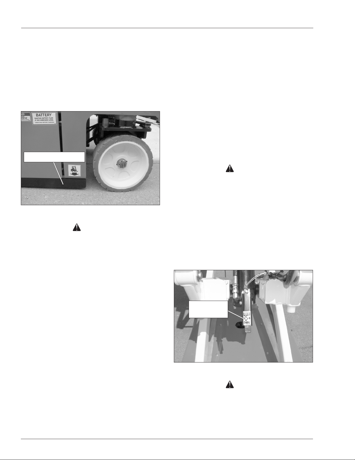
Emergency Lowering Lever
The emergency lowering lever may be used to lower
the platform if there is a malfunction in the hydraulic or
electrical system. The lever is mounted at the front of the
aerial platform (refer to Figure 4.5).
This protection system limits the tilt angle if a wheel is
driven into a drop-off or hole. This greatly reduces the
likelihood of the aerial platform tipping over.
The pothole protection system is for added protection and
does not justify operating near drop-offs or holes.
Drive/Lift Pothole Protector Interlock
The aerial platform drive and lift functions are interlocked
through a limit switch that senses whether or not the
pothole protection linkage is locked into position. The
drive/lift pothole interlock operates when the platform is
elevated approximately 6′ (1.8 m).
If an obstruction under the skids, or some other impairment prevents the skids from locking into position, the
drive and lift functions will not operate and an alarm will
sound.
Lower the platform and remove the obstruction when the
drive/lift pothole protector interlock alarm sounds.
Drive/Lift Level Sensor Interlock
The aerial platform drive and lift functions are interlocked
through a level sensor system. The drive/lift level sensor
Emergency
Lowering Lever
Figure 4.5 – Front of Machine
Danger
Pinch points exist on the scissors structure. Death or
serious injury will result if the scissors structure lowers onto personnel within the scissors arms or under
the raised platform. Stand clear while operating the
emergency lowering lever to lower the platform.
10 S3219E/S4732E – 1500834
Keep hands and ngers away from the scissors
structure components.
Push downward on the lever to lower the platform.
Safety Prop
The safety prop (refer to Figure 4.6) is used to support
the scissors structure when access to the scissors arm
components or the chassis is required. Always use the
safety prop when the platform is raised during inspection
and maintenance.
Safety Prop
Chapter 4 – Safety Devices
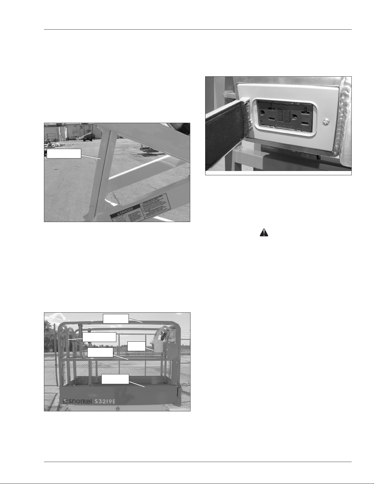
Ground Fault Circuit Interrupter
The electrical power outlet (refer to Figure 4.8), at the
platform contains a ground fault circuit interrupter (GFCI)
to provide protection for personnel.
Figure 4.8 – Upper Controls
Tilt Alarm
An alarm will sound if the aerial platform chassis is out
of level more than one and a half degrees side-to-side or
four degrees front-to-rear when the platform is raised.
Figure 4.6 – Safety Prop
Guardrails
The guardrails (refer to Figure 4.7) help protect personnel
from falling off the platform.
The guardrail system includes:
A top rail
A mid rail
Saloon style entry doors
Toeboards around the sides of the platform.
Top Rail
Entry Doors
Horn
Mid Rail
Toeboard
Danger
The aerial platform can tip over if it becomes unstable.
Death or serious injury will result from a tip-over
accident. Do not drive or position the aerial platform
for elevated use near any drop-off, hole, slope, soft
or uneven ground, or other tip-over hazard.
Completely lower the platform and drive to a level surface
when the tilt alarm sounds.
The tilt alarm is for added protection and does not justify op-
erating on anything other than rm, at, level surfaces.
Horn
The horn may be used to warn personnel on the ground.
The horn is operational when the machine is set up for
operation from the upper controls.
The horn button is located on the front of the upper control
panel (refer to Figure 4.7).
Flashing Light
An optional red or amber ashing light may be located
at the rear of the aerial platform. The ashing light warns
personnel that the aerial platform is in the area.
The light ashes at about one ash per second when the
Figure 4.7 – Platform
machine is set up for operation from the upper controls.
The entry doors allow for access to the platform. The
doors must be securely closed except when personnel
are entering or leaving the platform.
S3219E/S4732E – 1500834 11

Chapter 4 – Safety Devices
12 S3219E/S4732E – 1500834
Chapter 5 – Gauges and Displays
The aerial platform is equipped with several gauges to
monitor the condition of the machine before and during
operation.
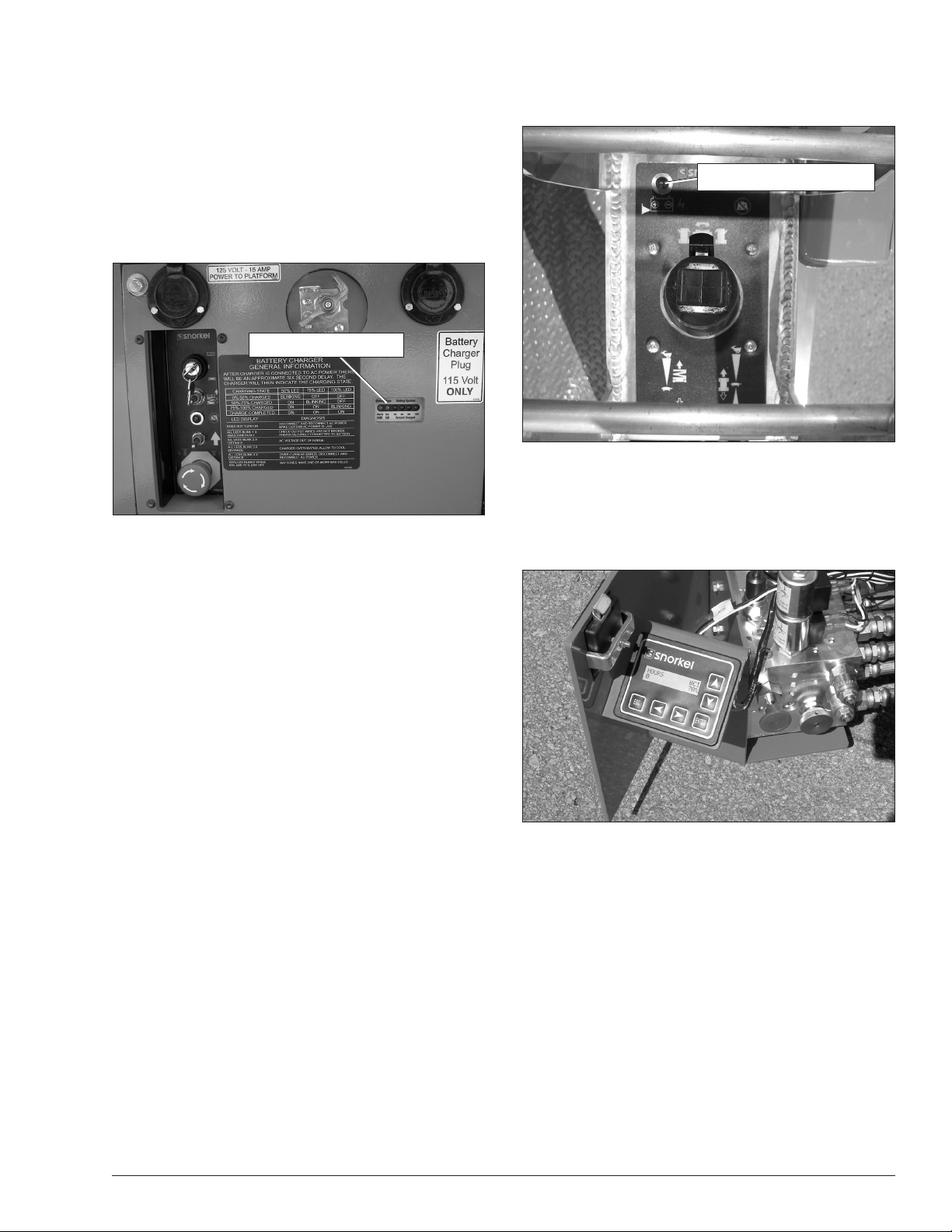
Battery Charge Indicator
The battery
which indicate the charger status.
The LED’s are visible on the battery tray.
charger has three LED’s
LED Charge Indicators
Figure 5.1 –Rear of Chassis
(refer to Figure 5.1)
Battery Condition Indicator
Figure 5.2 – Top of Upper Controls
Diagnostic Center Display
The diagnostic center LCD display (refer to Figure 5.3)
is located in the control valve tray on the right side of the
machine.
• 30% red LED blinking – indicates that the batteries
are 0% to 30% charged.
• 60% red LED blinking – indicates that the batteries
are 30% to 60% charged.
• 90% red LED blinking – indicates that the batteries
are 60% to 90% charged.
• 100% green LED solid On – indicates that the charge
cycle is complete.
Battery Condition Indicator
The battery condition indicator (refer to Figure 5.2) is
located on the top of the upper control panel. When the
light comes on, the lift function is cut out and drive speed
is reduced to slow.
Figure 5.3 – Diagnostic Center LCD Display
When the battery disconnect and emergency stop button at the lower controls are in the on position, the LCD
display shows:
• The accumulated aerial platform operating time
•
The available battery power to operate the machine.
S3219E/S4732E – 1500834 13

Chapter 5 – Gauges and Displays
14 S3219E/S4732E – 1500834
 Loading...