

Page 1

Operator’s
Manual
P/N 0410002
February,2001
Page 2

Electrical Hazard
DANGER
The aerial platform is not electrically insulated. Death or serious injury can result
from contact with, or inadequate clearance from, an energized conductor.
Do not go closer than the minimum safe approach distance as defined by the
Minimum Safe Approach Distance section in Chapter 3–Safety.
Regard all conductors as energized.
Allow for electrical wire sag and aerial platform sway.
If the platform, scissors structure, or any part of the aerial platform contacts a high-voltage electrical
conductor, the entire machine can become electrically charged.
If that happens, remain on the machine and do not contact any other structure or object. This includes
the ground, adjacent buildings, poles, and any other objects that are not part of the aerial platform.
Such contact could make your body a conductor to the other object, creating an electrical shock hazard
resulting in death or serious injury.
If an aerial platform is in contact with an energized conductor the platform operator must warn ground
personnel in the vicinity to stay away. Their bodies can conduct electricity creating an electrical shock
hazard resulting in death or serious injury.
Do not approach or leave the aerial platform until the electricity has been turned off.
Do not attempt to operate the lower controls when the platform, scissors structure, or any part of the
aerial platform is in contact with a high-voltage electrical conductor or if there is an immediate danger
of such contact.
Personnel on or near an aerial platform must be continuously aware of electrical hazards, recognizing
that death or serious injury can result from contact with an energized conductor.
Battery posts, terminals and related accessories contain
lead and lead components, chemicals known to the State
of California to cause cancer and birth defects or other
reproductive harm. Wash hands after handling.
S2545 – 0410002
Page 3

Table of Contents
Chapter 1. Introduction
Safety Alerts . . . . . . . . . . . . . . . . . . . . . . . . . . 1-1
Notes . . . . . . . . . . . . . . . . . . . . . . . . . . . . . . . . 1-1
Options . . . . . . . . . . . . . . . . . . . . . . . . . . . . . . 1-1
Operation. . . . . . . . . . . . . . . . . . . . . . . . . . . . . 1-1
Maintenance . . . . . . . . . . . . . . . . . . . . . . . . . . 1-2
Manual of Responsibilities. . . . . . . . . . . . . . . . 1-2
Additional Information . . . . . . . . . . . . . . . . . . . 1-2
Chapter 2. Specifications
Component Identification. . . . . . . . . . . . . . . . . 2-1
General Specifications. . . . . . . . . . . . . . . . . . . 2-2
Chapter 3. Safety
Electrocution Hazards . . . . . . . . . . . . . . . . . . . 3-1
Minimum Safe Approach Distance . . . . . . . 3-1
Prestart Inspection . . . . . . . . . . . . . . . . . . . . . 3-2
Work Place Inspection and Practices . . . . . . . 3-2
Operation. . . . . . . . . . . . . . . . . . . . . . . . . . . . . 3-2
Tip-Over and Falling Hazards . . . . . . . . . . . . . 3-3
Electrical System . . . . . . . . . . . . . . . . . . . . . . . 3-3
Hydraulic System. . . . . . . . . . . . . . . . . . . . . . . 3-3
Placards and Decals . . . . . . . . . . . . . . . . . . . . 3-3
Chapter 4. Safety Devices
Emergency Stop Controls . . . . . . . . . . . . . . . . 4-1
Drive Motion Alarm . . . . . . . . . . . . . . . . . . . . . 4-1
Lowering Alarm . . . . . . . . . . . . . . . . . . . . . . . . 4-1
Pothole Protector Skids . . . . . . . . . . . . . . . . . . 4-2
Drive/Lift Pothole Protector Interlock. . . . . . . . 4-2
Drive/Lift Level Sensor Interlock . . . . . . . . . . . 4-2
Guardrails . . . . . . . . . . . . . . . . . . . . . . . . . . . . 4-2
Emergency Lowering Handle . . . . . . . . . . . . . 4-2
Safety Prop . . . . . . . . . . . . . . . . . . . . . . . . . . . 4-3
Flashing Light . . . . . . . . . . . . . . . . . . . . . . . . . 4-4
Lanyard Anchors . . . . . . . . . . . . . . . . . . . . . . . 4-4
Horn. . . . . . . . . . . . . . . . . . . . . . . . . . . . . . . . . 4-4
Electrical Power Outlet . . . . . . . . . . . . . . . . . . 4-4
Chapter 5. Gauges
Hour Meter. . . . . . . . . . . . . . . . . . . . . . . . . . . . 5-1
Ammeter . . . . . . . . . . . . . . . . . . . . . . . . . . . . . 5-1
Battery Condition Indicator . . . . . . . . . . . . . . . 5-1
Chapter 6. Batteries
General Maintenance . . . . . . . . . . . . . . . . . . . 6-1
Charging . . . . . . . . . . . . . . . . . . . . . . . . . . . . . 6-1
Chapter 7. Controls
Lower Controls. . . . . . . . . . . . . . . . . . . . . . . . . 7-1
Battery Disconnect Switch . . . . . . . . . . . . . 7-1
Emergency Stop Switch . . . . . . . . . . . . . . . 7-1
Control Selector Switch. . . . . . . . . . . . . . . . 7-1
Platform Raise/Lower Switch . . . . . . . . . . . 7-1
Circuit Breaker Reset Button. . . . . . . . . . . . 7-1
Low Voltage Warning Light . . . . . . . . . . . . . 7-1
Upper Controls . . . . . . . . . . . . . . . . . . . . . . . . 7-2
Emergency Stop Button . . . . . . . . . . . . . . . 7-2
Drive/Lift Selector Switch . . . . . . . . . . . . . . 7-2
Joystick . . . . . . . . . . . . . . . . . . . . . . . . . . . . 7-2
Interlock . . . . . . . . . . . . . . . . . . . . . . . . . 7-2
Steer Switch . . . . . . . . . . . . . . . . . . . . . . 7-2
Low Voltage Warning Light . . . . . . . . . . . . . 7-3
Horn Button . . . . . . . . . . . . . . . . . . . . . . . . . 7-3
Battery Condition Indicator . . . . . . . . . . . . . 7-3
Chapter 8. Prestart Inspection
Operator’s Manual . . . . . . . . . . . . . . . . . . . . . . 8-2
Electrical System . . . . . . . . . . . . . . . . . . . . . . . 8-2
Battery Fluid Level . . . . . . . . . . . . . . . . . . . 8-2
Battery Terminals . . . . . . . . . . . . . . . . . . . . 8-2
Battery Charger. . . . . . . . . . . . . . . . . . . . . . 8-2
Cables and Wiring Harness . . . . . . . . . . . . 8-3
Hydraulic System. . . . . . . . . . . . . . . . . . . . . . . 8-3
Fluid Level. . . . . . . . . . . . . . . . . . . . . . . . . . 8-3
Hoses, Tubes, and Fittings . . . . . . . . . . . . . 8-3
Free-Wheeling Valve . . . . . . . . . . . . . . . . . . 8-4
Tires and Wheels. . . . . . . . . . . . . . . . . . . . . . . 8-4
Parking Brakes . . . . . . . . . . . . . . . . . . . . . . 8-4
Ground Strap . . . . . . . . . . . . . . . . . . . . . . . . . . 8-4
Lower Control Station . . . . . . . . . . . . . . . . . . . 8-4
Operating Controls . . . . . . . . . . . . . . . . . . . 8-4
Emergency Stop . . . . . . . . . . . . . . . . . . . . . 8-5
Lowering Alarm . . . . . . . . . . . . . . . . . . . . . . 8-5
Pothole Protector Interlock . . . . . . . . . . . . . . . 8-5
Level Sensor Interlock . . . . . . . . . . . . . . . . . . . 8-6
Emergency Lowering. . . . . . . . . . . . . . . . . . . . 8-6
Safety Prop . . . . . . . . . . . . . . . . . . . . . . . . . . . 8-6
Flashing Light . . . . . . . . . . . . . . . . . . . . . . . . . 8-7
Structures . . . . . . . . . . . . . . . . . . . . . . . . . . . . 8-7
Weldments . . . . . . . . . . . . . . . . . . . . . . . . . 8-7
Rollers and Slide Blocks . . . . . . . . . . . . . . . 8-7
Fasteners . . . . . . . . . . . . . . . . . . . . . . . . . . 8-7
Upper Control Station . . . . . . . . . . . . . . . . . . . 8-8
Guardrail System . . . . . . . . . . . . . . . . . . . . 8-8
Platform Extension . . . . . . . . . . . . . . . . . . . 8-8
Swing-Down Rails . . . . . . . . . . . . . . . . . . . . 8-8
Operating Controls . . . . . . . . . . . . . . . . . . . 8-8
Emergency Stop . . . . . . . . . . . . . . . . . . . . . 8-9
Lowering Alarm . . . . . . . . . . . . . . . . . . . . . . 8-9
Drive Motion Alarm . . . . . . . . . . . . . . . . . . . 8-9
Battery Condition Indicator . . . . . . . . . . . . . 8-9
Lanyard Anchors . . . . . . . . . . . . . . . . . . . . . 8-9
Horn . . . . . . . . . . . . . . . . . . . . . . . . . . . . . . 8-9
Electrical Power Outlet . . . . . . . . . . . . . . . . 8-9
Placards and Decals . . . . . . . . . . . . . . . . . . . 8-10
S2545 – 0410002
Page 4

Table of Contents
Chapter 9. Operation
Preparing for Operation . . . . . . . . . . . . . . . . . . 9-1
Lower Controls. . . . . . . . . . . . . . . . . . . . . . . . . 9-1
Upper Controls . . . . . . . . . . . . . . . . . . . . . . . . 9-1
Driving . . . . . . . . . . . . . . . . . . . . . . . . . . . . . 9-2
Drive Speeds . . . . . . . . . . . . . . . . . . . . . 9-2
Drive/Lift Level Sensor Interlock. . . . . . . 9-2
Steering. . . . . . . . . . . . . . . . . . . . . . . . . . . . 9-2
Platform. . . . . . . . . . . . . . . . . . . . . . . . . . . . 9-3
Raising and Lowering . . . . . . . . . . . . . . . 9-3
Extending . . . . . . . . . . . . . . . . . . . . . . . . 9-3
Lift-Up Entry Gate. . . . . . . . . . . . . . . . . . 9-4
Swing-Down Rails. . . . . . . . . . . . . . . . . . 9-4
Brakes . . . . . . . . . . . . . . . . . . . . . . . . . . . . . . . 9-5
Swing-Out Trays . . . . . . . . . . . . . . . . . . . . . . . 9-5
Electrical Power Outlet . . . . . . . . . . . . . . . . . . 9-6
Chapter 10. Stowing and Transporting
Stowing . . . . . . . . . . . . . . . . . . . . . . . . . . . . . 10-1
Transporting. . . . . . . . . . . . . . . . . . . . . . . . . . 10-1
Winching . . . . . . . . . . . . . . . . . . . . . . . . . . 10-1
Driving . . . . . . . . . . . . . . . . . . . . . . . . . . . . 10-2
Hoisting . . . . . . . . . . . . . . . . . . . . . . . . . . . 10-2
Lifting With a Forklift . . . . . . . . . . . . . . . . . 10-2
Securing for Transport. . . . . . . . . . . . . . . . 10-3
Chapter 11. Emergency Operation
Emergency Lowering. . . . . . . . . . . . . . . . . . . 11-1
Towing . . . . . . . . . . . . . . . . . . . . . . . . . . . . . . 11-1
Chapter 12. Troubleshooting
Troubleshooting Chart . . . . . . . . . . . . . . . . . . 12-1
Appendix A. Glossary
S2545 – 0410002
Page 5

Chapter 1. Introduction
CAUTIO
The aerial platform is a self-propelled scissors lift
used to raise personnel, their tools, and material
to the workstation. The platform is raised and
lowered with a hydraulic cylinder. Hydraulic
motors on each of the front drive wheels provide
power to move the aerial platform.
The aerial platform has been manufactured to
conform to all applicable requirements of the
following organizations.
●
Occupational Safety and Health
Administration (OSHA)
●
American National Standards Institute (ANSI)
●
Canadian Standards Association (CSA)
This manual provides information for safe and
proper operation of the aerial platform. Read and
understand the information in this manual before
operating the aerial platform on the job.
Additional copies of this manual may be ordered
from Snorkel. Supply the model and manual part
number from the front cover to assure that the
correct manual will be supplied.
All information in this manual is based on the
latest product information at the time of
publication. Snorkel reserves the right to make
product changes at any time without obligation.
■
Safety Alerts
A safety alert symbol is used throughout this
manual to indicate danger and caution
instructions. Follow these instructions to reduce
the likelihood of personal injury and property
damage. The terms danger and caution indicate
varying degrees of personal injury or property
damage that can result if the instruction is not
followed.
DANGER
Indicates a situation which if not avoided can
result in death or serious injury.
N
Indicates a situation which if not avoided can
result in minor injury or property damage.
■
Notes
Notes are used to provide special information or
helpful hints to assist in aerial platform operation, but
do not indicate a hazardous situation.
■
Options
This manual provides information about the
following options even though some machines
may not be equipped with them.
●
Horn
●
Flashing light
●
Lanyard anchors
●
Swinging platform gate
●
Fixed platform rails
●
AC generator
●
Battery condition indicator
●
Electrical power outlet with ground fault circuit
interrupter
■
Operation
The aerial platform has built-in safety features
and has been factory tested for compliance with
Snorkel specifications and industry standards.
However, any personnel lifting aerial platform can
be potentially dangerous in the hands of
untrained or careless operators.
DANGER
The potential for an accident increases when
the aerial platform is operated by personnel
who are not trained and authorized. Death or
serious injury can result from such accidents.
Read and understand the information in this
manual and on the placards and decals on the
machine before operating the aerial platform
on the job.
Training is essential and must be performed by a
qualified person. Become proficient in knowledge
and actual operation before using the aerial
platform on the job. You must be trained and
authorized to perform any functions of the aerial
platform. Operation of the aerial platform must be
within the scope of the machine specifications.
The operator bears ultimate responsibility for
following all manufacturer's instructions and
warnings, regulations and safety rules of their
employer and/or any state or federal law.
S2545 – 0410002 page 1 - 1
Page 6

Chapter 1. Introduction
■
Maintenance
Every person who maintains, inspects, tests, or
repairs the aerial platform must be qualified and
authorized to do so. Following the daily prestart
inspection in this Operator’s Manual will help
keep the aerial platform in optimum working
condition. Other maintenance functions must be
performed by maintenance personnel who are
qualified to work on the aerial platform.
Do not modify this aerial platform without prior
written consent of the Snorkel Engineering
Department. Modification may void the warranty,
adversely affect stability, or affect the operational
characteristics of the aerial platform.
■
Manual of Responsibilities
All owners and users of the aerial platform must
read, understand, and comply with all applicable
regulations. Ultimate compliance to OSHA
regulations is the responsibility of the user and
their employer.
ANSI publications clearly identify the
responsibilities of all personnel who may be
involved with the aerial platform. A reprint of the
“Manual of Responsibilities for Dealers, Owners,
Users, Operators, Lessors and Lessees of
ANSI/SIA A92.6-1990 Self-Propelled Elevating
Work Platforms” is available from Snorkel dealers
or from the factory upon request.
Copies are also available from:
Scaffold Industry Association
20335 Ventura Blvd. Suite 310
Woodland Hills, CA 91364-2471 USA
■
Additional Information
For additional information contact your local
dealer or Snorkel at:
Snorkel International, Inc.
P.O. Box 1160
St. Joseph, MO 64502-1160 USA
816-364-0317
http://www.snorkelusa.com
page 1 - 2 S2545 – 0410002
Page 7
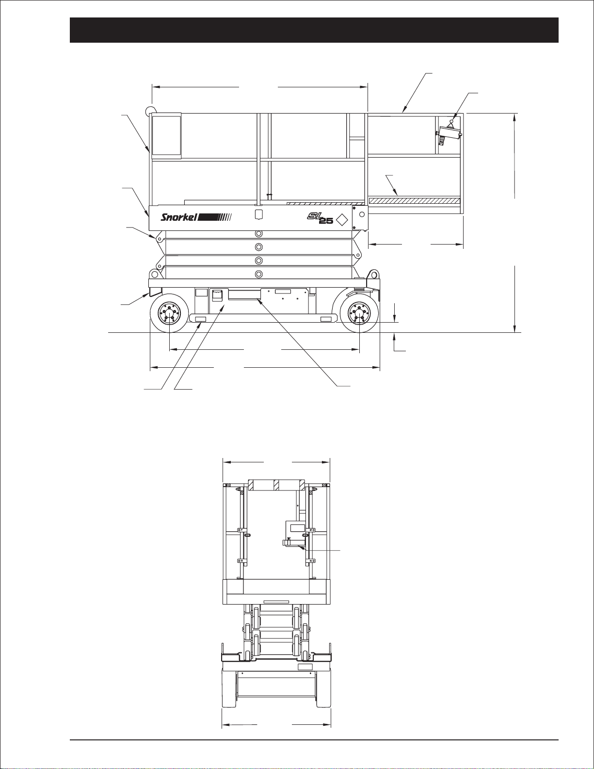
■
3
Component Identification
Guardrails
Platform
Scissors
Structure
Chassis
90 in
228.6 cm
Chapter 2. Specifications
Platform Extension
Upper Controls
Toeboards
78.5 in - 199.4 cm
Rails Lowered
36 in
91.4 cm
89 in - 226.1 cm
Rails Raised or
Fixed Rails
Rear
Pothole
Protector Skid
78 in
198.1 cm
95 in
241.3 cm
Hydraulic Tray (Right Side)
Battery Tray (Left Side)
44 in
111.8 cm
Front (Steer)
4 in - 10.2 cm Platform Lowered
1.25 in - 3.2 cm Platform Raised
Lower Controls
Operator’s
Manual Holder
45 in
cm
114.
S2545 – 0410002 page 2 - 1
Page 8

Chapter 2. Specifications
■
General Specifications
Maximum platform height . . . . . . . . . . . 25′ (7.6 m)
Working height . . . . . . . . . . . . . . . . . . . 31′ (9.4 m)
Platform size
Main . . . . . . . . . 44″ x90″ (111.8 cm x 228.6 cm)
Extension . . . . . . 36″ x40″ (91.4 cm x 101.6 cm)
Guardrail height
Platform. . . . . . . . . . . . . . . . . . . 44.3″ (112.5 cm)
Platform extension . . . . . . . . . . . . 43.3″ (110 cm)
Toeboard height . . . . . . . . . . . . . . . . . 6″ (15.2 cm)
Wheelbase . . . . . . . . . . . . . . . . . . . 78″ (198.1 cm)
Platform rated work load
Total . . . . . . . . . . . . . . . . . . . . . 850 lb (385.6 kg)
Platform extension. . . . . . . . . . . 250 lb (113.4 kg)
Weight (GVW approx.) . . . . . . 4,700 lb (2,131.9 kg)
Drive
Speed #1, elevated . . . . . . . . . 0.4 mph (0.6 kph)
Speed #2, stowed . . . . . . . . . . 1.1 mph (1.8 kph)
Speed #3, stowed . . . . . . . . . . 2.0 mph (3.2 kph)
Gradeability. . . . . . . . . . . . . . . . . . . . . . . . . . . 25%
Platform function speed
Platform raise
Speed #1 . . . . . . . . . . . . . . . . . . . . . . . 105 sec
Speed #2 . . . . . . . . . . . . . . . . . . . . . . . . 45 sec
Speed #3 . . . . . . . . . . . . . . . . . . . . . . . . 25 sec
Platform lower . . . . . . . . . . . . . . . . . . . . . 45 sec
Turning radius
Inside . . . . . . . . . . . . . . . . . . . . . . . 30″ (76.2 cm)
Outside . . . . . . . . . . . . . . . . . . . 115″ (292.1 cm)
Overall length . . . . . . . . . . . . . . . . . 95″ (241.3 cm)
Overall width . . . . . . . . . . . . . . . . . . 45″ (114.3 cm)
Ground clearance
Pothole protector lowered . . . . . . . 1.25″ (3.2 cm)
Pothole protector raised . . . . . . . . . . 4″ (10.2 cm)
Tires
Solid rubber, non-marking . . . . . . . . . . . . 16″ x5″
. . . . . . . . . . . . . . . . . . . . . (40.6 cm x 12.7 cm)
Electrical system. . . . . . . . . . . . . . . . . . . . 24 V DC
Hydraulic system
Maximum pressure. . . . . . 2,750 psi (18,961 kPa)
Hydraulic fluid recommended
Above 10°F (-13°C) . . . . . . . . . Mobil DTE-13M
. . . . . . . . . . . . . . . . . . . . . . . . . . (ISO VG32)
Below 10°F (-13°C) . . . . . . . . . Mobil DTE-11M
. . . . . . . . . . . . . . . . . . . . . . . . . . (ISO VG15)
Reservoir capacity
Total . . . . . . . . . . . . . . . . . 6.5 gal USA (24.6 L)
To full mark . . . . . . . . . . . . . 6 gal USA (22.7 L)
Ambient air temperature operating range
Fahrenheit . . . . . . . . . . . . . . . . . . . . 0°F to 110°F
Celsius . . . . . . . . . . . . . . . . . . . . . -18°C to 43°C
Drive system . . . . . . . . . . . . . . . . . . . 2 wheel drive
Overall height, stowed
Platform rails lowered . . . . . . . . 78.5″ (199.4 cm)
Platform rails raised . . . . . . . . . . . 89″ (226.1 cm)
Fixed platform rails . . . . . . . . . . . . 89″ (226.1 cm)
Floor loading pressure
Local concentrated pressure . . . . . . . . . . 213 psi
Overall uniform pressure . . . . . . . . . . . . . 187 psf
page 2 - 2 S2545 – 0410002
Page 9
Chapter 3. Safety
Knowledge of the information in this manual, and
proper training, provide a basis for safely
operating the aerial platform. Know the location of
all controls and how they operate to act quickly
and responsibly in an emergency.
Safety devices reduce the likelihood of an
accident. Never disable, modify, or ignore any
safety device. Safety alerts in this manual
indicate situations where accidents may occur.
If any malfunction, hazard or potentially unsafe
condition relating to capacity, intended use, or
safe operation is suspected, stop aerial platform
operation and seek assistance.
The operator bears ultimate responsibility for
following all manufacturer’s instructions and
warnings, regulations and safety rules of their
employer and/or any state or federal law.
■
Electrocution Hazards
The aerial platform is made of metal components
and is not insulated. Regard all conductors as
energized. Do not operate outside during a
thunderstorm.
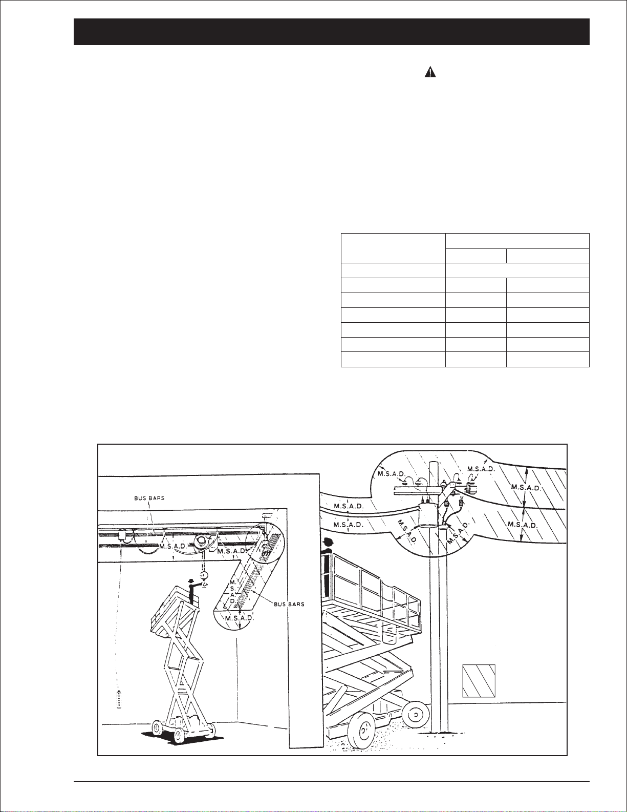
Minimum Safe Approach Distance
❑
Minimum safe approach distances to energized
power lines and their associated parts must be
observed while operating the aerial platform.
DANGER
The aerial platform is not electrically
insulated. Death or serious injury can result
from contact with, or inadequate clearance
from, an energized conductor. Do not go
closer than the minimum safe approach
distance as defined by ANSI.
ANSI publications define minimum distances that
must be observed when working near bus bars
and energized power lines. Table 1 and Figure 3
are reprinted courtesy of Scaffold Industry
Association, ANSI/SIA A92.6, page 26.
Voltage range
(phase to phase)
0 to 300V
Over 300V to 50kV
Over 50kV to 200kV
Over 200kV to 350kV
Over 350kV to 500kV
Over 500kV to 750kV
Over 750kV to 1000kV
Table 1—Minimum Safe Approach Distance
Minimum safe approach distance
(Feet) (Meters)
Avoid contact
10
15
20
25
35
45
3.05
4.60
6.10
7.62
10.67
13.72
Denotes
prohibited
zone
Figure 3—Minimum Safe Approach Distance
S2545 – 0410002 page 3 - 1
Page 10

Chapter 3. Safety
■
Prestart Inspection
Perform a prestart inspection before each shift as
described in Chapter 8. Do not use the aerial
platform on the job unless you are trained and
authorized to do so.
■
Work Place Inspection and Practices
Do not use the aerial platform as a ground
connection when welding. The welding ground
clamp must be attached to the same structure
that is being welded. Electrical current flow can
be very intense, causing serious internal damage
to some components.
Inspect the area before and during aerial platform
use. The following are some potential hazards
that may be in the work place.
●
Debris
●
Slopes
●
Drop-offs or holes
●
Bumps and floor obstructions
●
Overhead obstructions
●
Unauthorized persons
●
High voltage conductors
●
Wind and weather conditions
●
Inadequate surface and support to withstand
load forces applied by the aerial platform in
all operating configurations
DANGER
Pinch points may exist between moving
components. Death or serious injury can
result from becoming trapped between
components, buildings, structures, or other
obstacles. Make sure there is sufficient
clearance around the machine before moving
the chassis or platform. Allow sufficient room
and time to stop movement to avoid contact
with structures or other hazards.
Always look in the direction of movement. Drive
with care and at speeds compatible with the work
place conditions. Use caution when driving over
rough ground, on slopes, and when turning. Do
not engage in any form of horseplay or permit
riders any place other than in the platform.
Secure all accessories, containers, tools, and
other materials in the platform to prevent them
from accidentally falling or being kicked off the
platform. Remove all objects that do not belong in
or on the aerial platform.
Never steady the platform by positioning it
against another platform. Do not use boards, or
other temporary means to support or level the
aerial platform.
Do not operate the aerial platform if it is damaged
or not functioning properly. Qualified maintenance
personnel must correct the problem before
putting the aerial platform back into service.
Before using the aerial platform in any hazardous
(classified) location, make certain it is approved
and of the type required by ANSI/NFPA 505 for
use in that particular location.
Know and understand the job site traffic-flow
patterns and obey the flagmen, road signs, and
signals.
While operating the aerial platform, a good safety
practice is to have qualified personnel in the
immediate area to:
●
Help in case of an emergency
●
Operate emergency controls as required
●
Watch for loss of control by platform operator
●
Warn the operator of any obstructions or
hazards that may not be obvious to them
●
Watch for soft terrain, sloping surfaces,
drop-offs, etc. where stability could be
jeopardized
●
Watch for bystanders and never allow anyone
to be under, or to reach through, the scissors
structure while operating the aerial platform
■
Operation
Use three points of support when entering or
exiting the platform. For example, use two hands
and one foot when climbing into the platform.
Make sure the area below the platform is free of
personnel before lowering.
Keep both feet positioned firmly on the platform
floor. Operate the controls slowly and deliberately
to avoid jerky and erratic operation. Always stop
the controls in neutral before going in the
opposite direction.
Do not dismount while the aerial platform is in
motion or jump off the platform.
Properly stow the aerial platform and secure it
against unauthorized operation at the end of
each work day, before transporting, or if it is left
unattended.
page 3 - 2 S2545 – 0410002
Page 11

■
Tip-Over and Falling Hazards
Operate the aerial platform only on a firm, flat,
level surface capable of withstanding all load
forces imposed by the aerial platform in all
operating conditions. Raise the platform only
when the aerial platform is on level ground.
Do not operate the machine within 4′ (1.2 m) of
any drop-off or hole.
It is best not to transfer from the platform to
another structure or vice versa, unless that is the
safest way to do the job. Judge each situation
separately taking the work environment into
account. If it is necessary to transfer from the
platform to another structure use the platform
entrance. Do not climb over the guardrails.
Do not operate the aerial platform in windy or
gusty conditions. Do not add anything to the
aerial platform that will increase the wind loading
such as billboards, banners, flags, etc.
Chapter 3. Safety
DANGER
Batteries give off hydrogen and oxygen that
can combine explosively. Death or serious
injury can result from a chemical explosion.
Do not smoke or permit open flames or
sparks when checking the batteries.
Battery acid can damage the skin and eyes.
Serious infection or reaction can result if
medical treatment is not given immediately.
Wear face and eye protection when working
near the batteries.
Batteries contain sulfuric acid that can damage
your eyes or skin on contact. Wear a face shield,
rubber gloves, and protective clothing when
working around batteries. If acid contacts your
eyes, flush immediately with clear water and get
medical attention. If acid contacts your skin, wash
off immediately with clear water.
Never operate the aerial platform without all parts
of the guardrail system in place and the safety
chain or gate closed.
Do not exceed the platform capacity as indicated
on the platform rating placard on the platform.
Carry all loads from inside the platform.
Do not operate the aerial platform from trucks,
trailers, railway cars, floating vessels, scaffolds,
or similar equipment unless the application is
approved in writing by Snorkel.
Do not use the aerial platform as a crane, hoist,
jack, or for any purpose other than to position
personnel, tools, and materials.
Do not climb on the guardrails or use ladders,
planks, or other devices to extend or increase the
work position from the platform.
Take care to prevent rope, electrical cords, and
hoses, etc., from becoming caught in or on the
aerial platform. If the platform or scissors
structure becomes caught on an adjacent
structure or other obstacle and is prevented from
normal motion, reverse the control to free the
platform. If control reversal does not free the
platform, evacuate the platform before attempting
to free it.
■
Electrical System
Charge batteries in a well-ventilated area free of
flame, sparks, or other hazards that might cause
fire or explosion.
■
Hydraulic System
The hydraulic system contains hoses with
hydraulic fluid under pressure.
DANGER
Hydraulic fluid escaping under pressure can
have enough force to inject fluid into the
flesh. Serious infection or reaction can result
if medical treatment is not given immediately.
In case of injury by escaping hydraulic fluid,
seek medical attention at once.
Do not place your hand or any part of your body
in front of escaping hydraulic fluid. Use a piece of
cardboard or wood to search for hydraulic leaks.
■
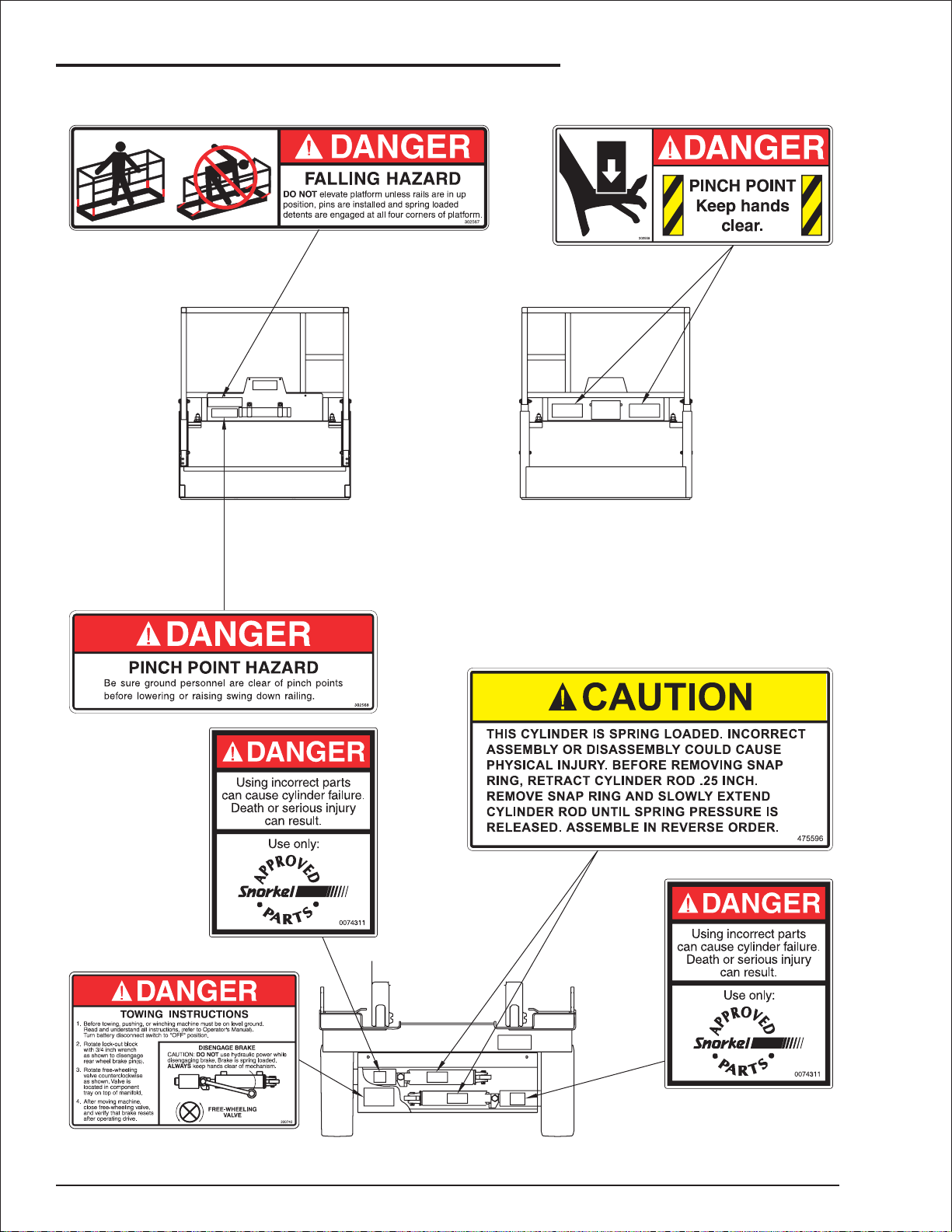
Placards and Decals
The aerial platform is equipped with placards and
decals that provide instruction for operation and
accident prevention. Do not operate the aerial
platform if any placards or decals are missing or
not legible. The location, part numbers and
descriptions of all placards and decals are
illustrated in Chapter 8 under Placards and
Decals.
The placards and decals may be cleaned with
soap and water, and a soft cloth if the words or
pictures cannot be seen. Do not use solvents.
The safety related placards and decals are
illustrated on the following pages.
S2545 – 0410002 page 3 - 3
Page 12
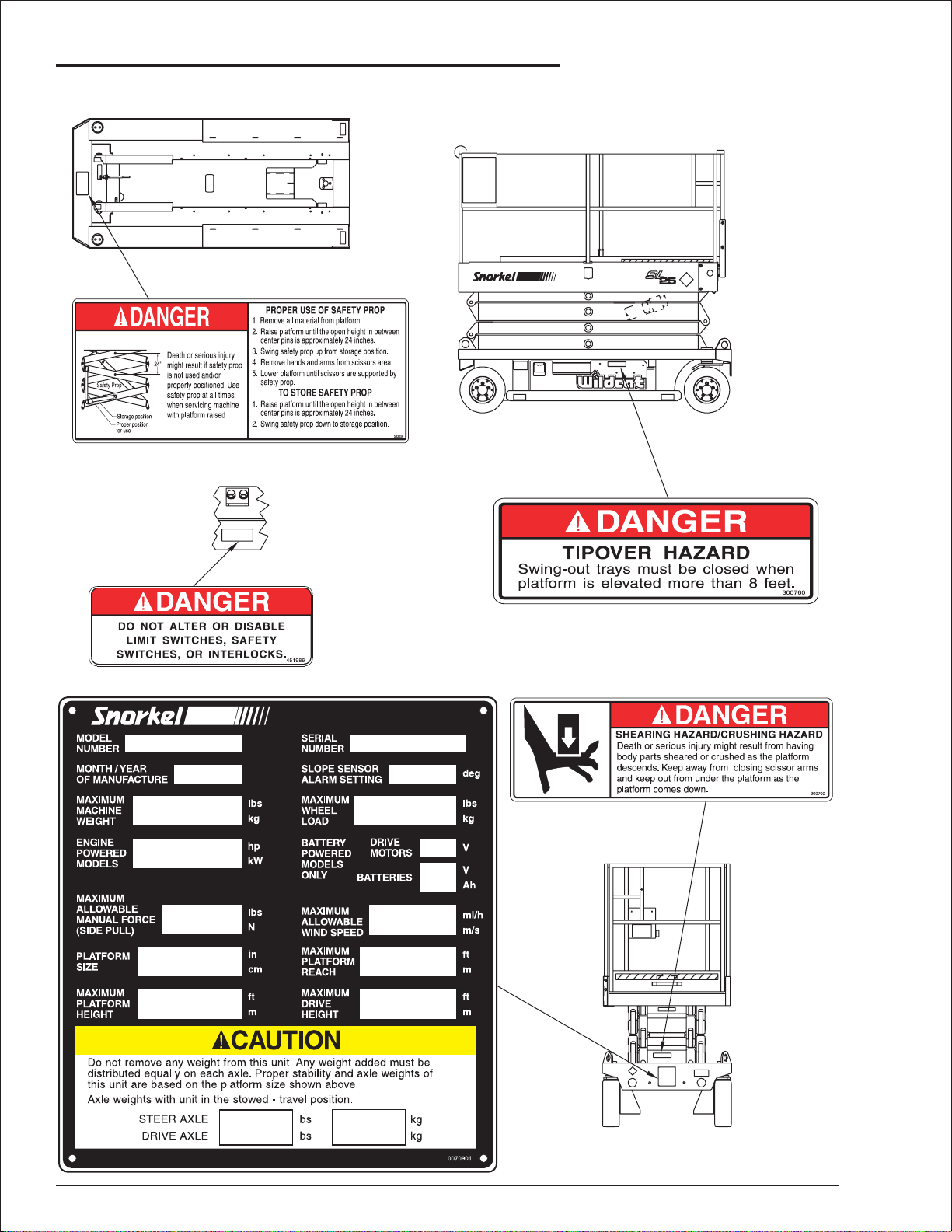
Chapter 3. Safety
Top of Chassis
2nd Inner Arm Top
Right Side
Front
page 3 - 4 S2545 – 0410002
Page 13
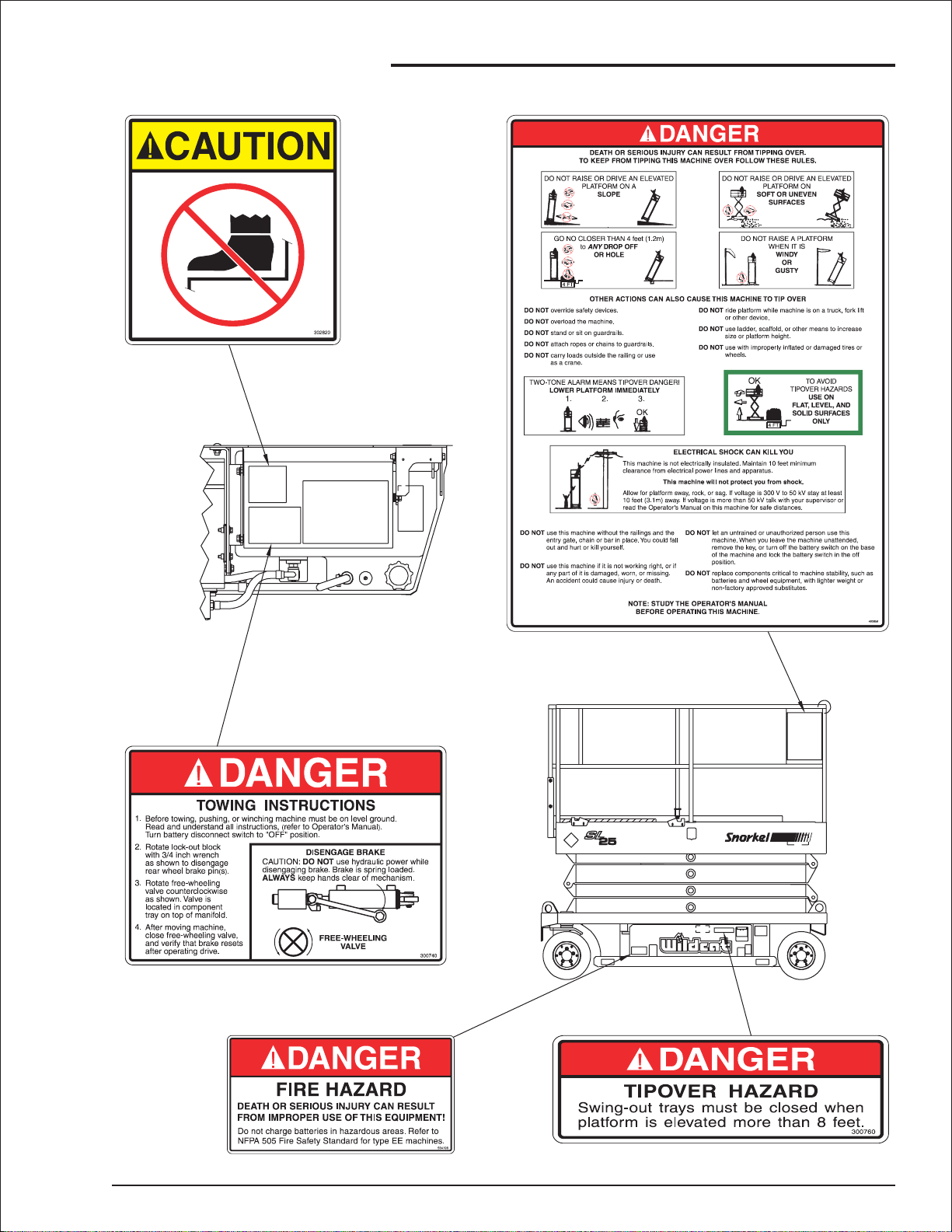
Chapter 3. Safety
Top of Control Panel
in HydraulicTray
(Both Sides)
Left Side
(EE Machines Only)
S2545 – 0410002 page 3 - 5
Page 14
Chapter 3. Safety
Swing-Down Platform Rails
Rear of Chassis
page 3 - 6 S2545 – 0410002
Page 15
This aerial platform is manufactured with safety
devices, placards, and decals to reduce the
likelihood of an accident. For the safety of all
personnel, do not disable, modify, or ignore any
safety device. Safety devices are included in the
daily prestart inspection.
DANGER
The potential for an accident increases when
safety devices do not function properly. Death
or serious injury can result from such
accidents. Do not alter, disable, or override
any safety device.
Chapter 4. Safety Devices
Horn
Button
Emergency
Stop Button
If any safety devices are defective, remove the
aerial platform from service until qualified
maintenance personnel can make repairs.
■
Emergency Stop Controls
There is an emergency stop control at the lower
and upper control station.
At the lower controls, the emergency stop is a
two-position toggle switch (refer to Figure 4.1)
with a red safety guard. Push the red safety
guard down over the toggle switch to disconnect
power to all control circuits. Lift the guard and
push the toggle switch up to restore power.
Circuit Breaker
Reset Button
Platform
Raise/Lower
Switch
Control Selector
Switch
Low Voltage
Warning Light
Battery
Disconnect
Switch
Emergency
Stop Switch
Figure 4.1—Lower Control Station
Figure 4.2—Upper Control Station
Push the emergency stop button in to disengage
power to all control circuits. Pull the button out to
restore power.
■
Drive Motion Alarm
When the joystick is positioned to move the aerial
platform forward or in reverse, the drive motion
alarm emits a loud beeping sound. This alarm
warns personnel in the work area to stand clear.
■
Lowering Alarm
When the platform is being lowered, an alarm
sounds to warn personnel in the work area to
stand clear.
DANGER
Pinch points exist on the scissors structure.
Death or serious injury can result if the
scissors structure lowers onto personnel
within the scissors arms or under the raised
platform. Make sure all personnel stand clear
while raising and lowering the platform.
Be careful when lowering the platform. Keep
hands and fingers away from the scissors
structure components.
NOTE
The lower controls override the upper controls. If
the upper control emergency stop button is
engaged the lower controls can still be used to
operate the aerial platform.
At the upper controls, the emergency stop is a
two-position push button (refer to Figure 4.2).
S2545 – 0410002 page 4 - 1
Page 16
Chapter 4. Safety Devices
■
Pothole Protector Skids
The pothole protector skids automatically lower
when the platform is elevated approximately 24″.
Ground clearance is reduced from 4″ to about
1
″ when the skids lock into position (refer to
1
4
Figure 4.3).
Pothole Protector Skid
Figure 4.3—Pothole Protector Skids
DANGER
The aerial platform can tip over if it becomes
unstable. Death or serious injury can result
from a tip-over accident. Do not drive or
position the aerial platform for elevated use
within four feet of any drop-off, hole, or other
tip-over hazard.
This protection system limits the tilt angle if a
wheel is driven into a drop-off or hole. This
greatly reduces the likelihood of the aerial
platform tipping over.
The pothole protection system is for added
protection and does not justify operating near
drop-offs or holes.
■
Drive/Lift Pothole Protector Interlock
The aerial platform drive and lift functions are
interlocked through a limit switch that senses
whether or not the pothole protection linkage is
locked into position. The drive/lift pothole interlock
operates when the platform is elevated
approximately seven feet.
If an obstruction under the skids, or some other
impairment prevents the skids from locking into
position, the drive and lift functions will not
operate and an alarm will sound.
■
Drive/Lift Level Sensor Interlock
The aerial platform drive and lift functions are
interlocked through a level sensor system. The
drive/lift level sensor interlock operates when the
platform is elevated approximately seven feet.
If the aerial platform chassis is tilted more than
two degrees side-to-side or four degrees
front-to-rear, the drive and lift functions will not
operate and an alarm will sound.
Lower the platform and drive to a level surface
when the drive/lift level sensor alarm sounds.
The drive/lift level sensor system is for added
protection and does not justify operating on
anything other than firm, flat, level surfaces.
■
Guardrails
The guardrail system includes a top rail, mid rail,
and toeboards around the sides of the platform
(refer to Figure 4.4).
Top Rail
Mid Rail
Toeboard
Entry Chain
Figure 4.4—Guardrails
A safety chain or an optional swinging gate
allows for access to the platform. The swinging
gate closes automatically after entering or exiting
the platform. The chain or gate is part of the
guardrail system and must be securely fastened
after entering the platform.
■
Emergency Lowering Handle
The emergency lowering handle may be used to
manually lower the platform if there is a
malfunction in the hydraulic or electrical system.
The handle (refer to Figure 4.5) is mounted at the
front of the aerial platform.
Lower the platform and remove the obstruction
when the drive/lift pothole protector interlock
alarm sounds.
page 4 - 2 S2545 – 0410002
Page 17

Emergency
Lowering Handle
Figure 4.5—Emergency Lowering Handle
Chapter 4. Safety Devices
DANGER
Pinch points exist on the scissors structure.
Death or serious injury can result if the
scissors structure drops onto personnel
working within the scissors arms or under the
raised platform. Properly position the safety
prop before reaching through the scissors
structure.
When inspecting or servicing the aerial platform
with the platform raised, use the following
procedure to properly position the safety prop.
1. Remove all tools and material from the
platform.
The emergency lowering handle may be used to
lower the scissors arms onto the safety prop
before inspecting the machine.
■
Safety Prop
The safety prop (refer to Figure 4.6) is used to
support the scissors structure when access to the
scissors arm components or the chassis is
required. Always use the safety prop when the
platform is raised during inspection and
maintenance.
Safety Prop
24"
2. Using the lower controls, raise the platform
until the open height between the arm center
pins is approximately 24″ (refer to Figure 4.6).
3. Swing the safety prop upward from the
storage position to the support position.
4. Remove hands and arms from the scissors
structure area.
5. Lower the platform until the scissors are
supported by the safety prop.
Use the following procedure to stow the safety
prop.
1. Using the lower controls, raise the platform
until the open height between the arm center
pins is approximately 24″.
2. Swing the safety prop down to the stowed
position.
Figure 4.6—Safety Prop
S2545 – 0410002 page 4 - 3
Page 18

Chapter 4. Safety Devices
■
Flashing Light
An optional flashing light may be located at the
front of the aerial platform (refer to Figure 4.7).
The flashing light warns personnel that the aerial
platform is in the area.
Flashing Light
Figure 4.7—Flashing Light
The light flashes at about one flash per second
when the machine is set up for operation from the
upper controls.
■
Horn
The optional horn (refer to Figure 4.2) may be
used to warn personnel on the ground. The horn
is operational when the machine is set up for
operation from the upper controls.
■
Electrical Power Outlet
The optional electrical power outlet (refer to
Figure 4.9) at the platform contains a ground fault
circuit interrupter (GFCI) to help prevent
accidental conductor grounding.
■
Lanyard Anchors
Two optional lanyard anchors for fall restraint
anchorage may be provided, one at the front of
the platform extension (refer to Figure 4.8) and
one at the side of the platform.
Lanyard Anchor
Figure 4.8—Lanyard Anchors
NOTE
The lanyard anchors are not for lifting or tying the
machine down.
Figure 4.9—Electrical Power Outlet
If local work rules require the use of a fall
restraint device, properly connect it to a lanyard
anchor before raising the platform. Do not use the
aerial platform for
page 4 - 4 S2545 – 0410002
personal fall arrest
anchorage.
Page 19

Chapter 5. Gauges
The aerial platform is equipped with an ammeter,
an hour meter and may have an optional battery
condition indicator.
■
Hour Meter
The hour meter is located at the lower controls
(refer to Figure 5.1). It measures the accumulated
aerial platform operating time.
Hour Meter
Figure 5.1—Lower Controls
■
Battery Condition Indicator
The optional battery condition indicator (refer to
Figure 5.3) is located on the upper control panel.
It displays the level of available battery power to
operate the aerial platform. The number one on
the scale indicates full power and zero indicates
no power.
Battery Condition
Indicator
Figure 5.3—Battery Condition Indicator
■
Ammeter
The ammeter is located on the battery charger
(refer to Figure 5.2). When the batteries are
charging, the ammeter displays the level of
current flow to the batteries.
Ammeter
Figure 5.2—Battery Charger
S2545 – 0410002 page 5 - 1
Page 20

Chapter 6. Batteries
CAUTIO
The battery tray contains 4, 240 amp, 6 volt
batteries. The batteries supply 24 volt DC
electrical power to operate the aerial platform
electrical and electro hydraulic components.
Proper machine operation depends on well
maintained and charged batteries.
■
General Maintenance
Always keep the batteries clean, free of dirt and
corrosion. A film on top of the battery can
accelerate discharge.
Cold reduces battery capacity and retards
charging. Heat increases water usage and can
result in overcharging. Very high temperatures
can cause thermal run away which may lead to
an explosion or fire. Consult a battery charger
specialist if extreme temperature use is
unavoidable.
DANGER
Battery acid can damage the skin and eyes.
Serious infection or reaction can result if
medical treatment is not given immediately.
Wear face and eye protection when working
near the batteries.
N
The batteries can be overcharged and/or
damaged if the charger fails to shut off
automatically. Do not leave the battery
charger on for more than two days.
It may take from 1½ to 16 hours to recharge the
batteries depending on the amount of discharge.
If the charging cycle exceeds 16 hours without
the batteries being fully recharged, shut off the
charger and have the batteries checked.
Use the following procedure to charge the
batteries.
1. Turn the battery disconnect switch off (refer
to Figure 6.1).
Battery
Disconnect
Switch
Use distilled water to refill the batteries. Avoid
water containing metallic solids such as iron.
■
Charging
Fully recharge the batteries, immediately after
use. One charging cycle per day is preferred.
Fully charged batteries perform best. The deeper
the discharge, the fewer number of cycles a
battery will deliver. Deep discharges deteriorate
the battery quicker than light shallow cycles.
An overly discharged battery may need to be
cycled a few times before it can fully recover. If a
battery begins to heat before becoming fully
charged, it may be necessary to recharge and
discharge the battery a few times.
The aerial platform is equipped with an automatic
battery charger that will completely recharge the
batteries and turn off after the charge cycle is
completed.
DANGER
Batteries give off hydrogen and oxygen that
can combine explosively. Death or serious
injury can result from a chemical explosion.
Charge the batteries only in a well ventilated
area away from sparks or flame.
Figure 6.1—Lower Controls
2. Check the battery water level. Add water to
individual cells only if the plates are exposed.
3. Plug the charger into a properly grounded
outlet using a 3 conductor, 14 gauge or
larger extension cord. After a short delay the
charger will turn on. The ammeter (refer to
Figure 6.2) will indicate near 20 amps initially
then taper off to 5 to 10 amps as the
batteries charge.
Ammeter
Figure 6.2—Battery Charger
S2545 – 0410002 page 6 - 1
Page 21

Chapter 6. Batteries
NOTE
If the batteries are fully charged when the
charger is plugged in, the ammeter will initially
read 15 to 20 amps then quickly read zero.
4. Leave the charger plugged in until it shuts
itself off.
5. Unplug the extension cord after the battery
charger turns itself off. Allow the batteries to
cool off after charging.
6. Check the battery water level and refill cells
as necessary.
page 6 - 2 S2545 – 0410002
Page 22

Chapter 7. Controls
CAUTIO
CAUTIO
Aerial platform functions may be operated with
controls at the lower control station or the upper
control station.
■
Lower Controls
The lower controls (refer to Figure 7.1) are
located in the hydraulic tray on the right side of
the chassis. The following are located at the
lower control station.
●
Battery disconnect switch
●
Emergency stop switch
●
Control selector switch
●
Platform raise/lower switch
●
Circuit breaker reset button
●
Low voltage warning light
Circuit Breaker
Reset Button
Control Selector
Switch
Battery
Disconnect
Switch
Emergency Stop Switch
❑
The emergency stop is a two-position toggle
switch with a red safety guard. Push the red
safety guard down over the toggle switch to
disconnect power to all control circuits. Lift the
guard and push the toggle switch up to restore
power.
Control Selector Switch
❑
Place the control selector switch in the down
position to operate aerial platform functions from
the lower controls. The upper controls will not
operate while the control selector is in the lower
position.
Place the selector switch in the up position to
operate the aerial platform functions from the
upper controls.
Platform Raise/Lower Switch
❑
Pull up on the platform switch to raise the
platform. Release the switch when the desired
height is reached.
Platform
Raise/Lower
Switch
Low Voltage
Warning Light
Emergency
Stop Switch
Figure 7.1—Lower Controls
❑
Battery Disconnect Switch
The battery disconnect removes electrical power
from all electrically controlled functions when in
the off position. Place the switch in the on
position to operate any electrically controlled
function.
N
Only authorized personnel should operate the
aerial platform. Unqualified personnel may
cause injury to coworkers or property
damage. Lock the battery disconnect switch
in the off position before leaving the aerial
platform unattended.
Lock the battery disconnect switch in the off
position to prevent unauthorized use of the aerial
platform.
Push down on the switch to lower the platform.
The lowering alarm will sound as the platform
lowers.
❑
Circuit Breaker Reset Button
A circuit breaker is located in the electrical power
line of the lower control panel. The circuit breaker
protects the wiring and components from
electrical overload in case of a short circuit or
other fault.
Push the button to reset the circuit breaker.
N
A tripped circuit breaker indicates a
malfunction in the electrical system.
Component damage can result if the cause of
the malfunction is not corrected. Do not
operate the aerial platform if the circuit
breaker trips repeatedly.
❑
Low Voltage Warning Light
When the voltage of the battery pack falls to a
preset level too low for proper machine operation
the following happens.
●
The low voltage warning light turns on
●
An alarm sounds
●
The platform will not raise
S2545 – 0410002 page 7 - 1
Page 23

Chapter 7. Controls
Lower the platform to the stowed position when
the warning light is on and the alarm is activated.
Drive to a battery recharging area and fully
recharge the battery pack before returning the
aerial platform to service.
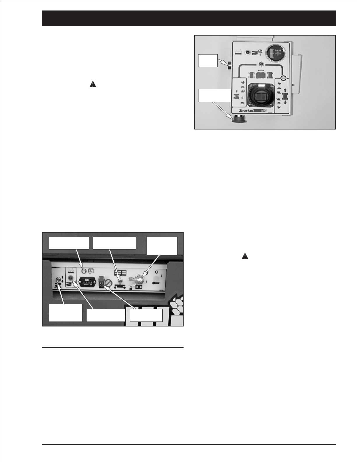
■
Upper Controls
The upper controls (refer to Figure 7.2) are
located on the control box at the platform. The
following are located at the upper control station.
●
Emergency stop button
●
Drive/lift selector switch
●
Joystick to control platform lift, drive and steer
●
Low voltage warning light
The optional horn button and battery condition
indicator gauge may also be located at the upper
control station.
Low Voltage
Warning Light
Horn
Button
Interlock
Switch
Steer
Switch
Emergency Stop Button
Battery
Condition
Indicator
Drive/Lift
Selector
Switch
Joystick
Figure 7.2—Upper Controls
❑
Emergency Stop Button
The emergency stop is a two-position red push
button on the front of the upper control box. Push
the button in to disconnect power to all control
circuits at the upper controls. Pull the button out
to restore power.
NOTE
The lower controls override the upper controls. If
the upper control emergency stop button is
engaged the lower controls can still be used to
operate the aerial platform.
Drive/Lift Selector Switch
❑
Place the drive/lift selector switch in the drive
position to drive the aerial platform using the
joystick. The platform will not raise or lower while
driving.
Place the drive/lift selector switch in the lift
position to raise and lower the platform using the
joystick.
Joystick
❑
The joystick (refer to Figure 7.2) allows for
operating more than one function at a time. Use
the joystick to operate the following functions.
●
Aerial platform steering
●
Aerial platform drive and speed
●
Platform raise/lower and speed
Movement of the joystick in a given direction
produces a corresponding movement of the
aerial platform. The steering and drive functions
may be operated separately or simultaneously.
Interlock
◆
The joystick has an interlock switch in the handle.
Engage the interlock by grasping the joystick and
pulling the switch toward the handle. Engage the
interlock to activate the steering, drive, or lift
functions.
◆
Steer Switch
The steer switch is a momentary contact, rocker
switch on top of the joystick. This switch controls
the two front wheels to steer the aerial platform.
To steer to the right, engage the interlock on the
joystick and hold down the right side of the steer
switch. To steer to the left, engage the interlock
on the joystick and hold down the left side of the
steer switch.
NOTE
The steering wheels are not self-centering. Set
the steering wheels straight ahead after
completing a turn.
Push the emergency stop button in when the
upper controls are not in use to help protect
against unintentional platform operation.
page 7 - 2 S2545 – 0410002
Page 24

Low Voltage Warning Light
❑
When the voltage of the battery pack falls to a
preset level too low for proper machine operation
the following happens.
●
The low voltage warning light turns on
●
An alarm sounds
●
The platform will not raise
Lower the platform to the stowed position when
the warning light is on and the alarm is activated.
Drive to a battery recharging area and fully
recharge the battery pack before returning the
aerial platform to service.
Horn Button
❑
The optional horn button is on the left side of the
upper control box. Press the push button switch
to sound the horn.
Battery Condition Indicator
❑
The optional battery condition indicator gauge is
on the top of the upper control box. It indicates
the level of available battery power to operate the
aerial platform.
Chapter 7. Controls
S2545 – 0410002 page 7 - 3
Page 25

Chapter 8. Prestart Inspection
Potential service and safety problems may be
detected by inspecting the aerial platform every
day. This chapter includes a prestart inspection
table (refer to Figure 8.1) and information on
properly inspecting each item listed in the table.
Perform a prestart inspection at the beginning of
each shift before using the aerial platform on the
The potential for an accident increases when
operating an aerial platform that is damaged or
malfunctioning. Death or serious injury can
result from such accidents. Do not operate the
aerial platform if it is damaged or malfunctioning.
DANGER
job. The inspection site must have a smooth and
level surface. Use the prestart inspection table to
ensure no areas are overlooked.
Item Inspect for
Operator’s manual In manual holder
Electrical system
Battery fluid level
Battery terminals
Battery charger
Cables and wiring harness
Hydraulic system
Fluid level
Hoses, tubes, and fittings
Free-wheeling valve
Tires and wheels Good condition
Parking brakes Proper cam orientation
Ground strap In place and securely fastened
Lower control station
Operating controls
Emergency stop
Lowering alarm
Pothole protector interlock Proper operation
Level sensor interlock Proper operation
Emergency lowering Proper operation
Safety prop No damage or deformation
Flashing light Proper operation
Structures
Weldments
Rollers and slide blocks
Fasteners
Upper control station
Guardrail system
Platform extension
Swing-down rails
Operating controls
Emergency stop
Lowering alarm
Drive motion alarm
Battery condition indicator
Lanyard anchors
Horn
Electrical power outlet
Placards and decals In place and readable
Proper level
Clean, connections tight
Proper operation
No wear or physical damage
Between Full and Add marks
No leaks
Fully closed
Proper operation
Shuts off lower controls
Sounds when platform lowers
Welds intact, no damage or deformation
Proper operation, no damage
In place and tight
Welds intact, no damage or deformation
All components in place, no damage or deformation
Proper operation
Fasteners in place, proper operation
Proper operation
Shuts off upper controls
Sounds when platform lowers
Sounds when aerial platform moves
Proper operation
No damage or deformation
Sounds when activated
Proper operation
Figure 8.1—Prestart Inspection Table
S2545 – 0410002 page 8 - 1
Page 26

Chapter 8. Prestart Inspection
CAUTIO
■
Operator’s Manual
Make certain the manual holder (refer to Figure
8.2) is securely fastened to the platform.
Figure 8.2—Operator’s Manual Holder
Caps
Terminals
Figure 8.3—Batteries
Replace the caps on the batteries. The caps must
be in place and tight during machine operation
and battery charging.
Check to see that the proper Operator’s manual
is with the aerial platform. The manual should be
complete with all pages intact and in readable
condition.
■
Electrical System
Electrical power is supplied from 4, 240 amp, 6
volt batteries. These batteries supply 24 volt DC
electrical power to operate the aerial platform
electrical and electro hydraulic components.
DANGER
Batteries give off hydrogen and oxygen that
can combine explosively. Death or serious
injury can result from a chemical explosion.
Do not smoke or permit open flames or
sparks when checking the batteries.
N
Even with low voltage electrical systems,
severe arcing can occur. Electrical shock or
component damage can result from contact
with energized conductors. Use caution when
working with any electrical device.
Battery Terminals
❑
Check the battery terminals and cable ends (refer
to Figure 8.3). They should be clean and free of
corrosion and dirt. If necessary, clean the
terminals and cable ends with a wire brush or
terminal cleaning tool. All cable ends must be
securely fastened to the terminals.
❑
Battery Charger
Inspect the battery charger (refer to Figure 8.4) to
ensure that it is operating properly.
1. Turn the battery disconnect switch off.
2. Plug the charger into a source of power.
3. Observe the reading on the ammeter. The
reading should be 20 amps.
Ammeter
The batteries are in the swing-out tray on the left
side of the aerial platform.
❑
Battery Fluid Level
Remove the caps from each battery (refer to Figure
8.3). Visually check the battery fluid level. If the level
is not within
inside each hole, add distilled water.
page 8 - 2 S2545 – 0410002
1
″ (6 mm) of the bottom of the filler neck
4
Figure 8.4—Battery Charger
Page 27

Cables and Wiring Harness
CAUTIO
❑
Inspect all cables and wiring for wear and/or
physical damage such as loose connections,
broken wires, and frayed insulation. Check the
wiring in areas where a change in routing
direction may cause them to become pinched
(refer to Figure 8.5). Make sure the cables and
wires are properly routed to avoid sharp edges,
pinching, and scuffing.
Chapter 8. Prestart Inspection
Figure 8.6—Fluid Level Indicator
N
Not all hydraulic fluid is suitable to use in the
hydraulic system. Some have poor lubricating
characteristics and can increase component
wear. Only use hydraulic fluid as
recommended.
Figure 8.5—Cables and Wiring Harness
■
Hydraulic System
Hydraulic power is supplied from a single stage
hydraulic pump with a 4.1 horsepower DC
electrical motor.
DANGER
Hydraulic fluid escaping under pressure can
have enough force to inject fluid into the
flesh. Serious infection or reaction can result
if medical treatment is not given immediately.
In case of injury by escaping hydraulic fluid,
seek medical attention at once.
The hydraulic reservoir, pump, filter, and control
valve is located in the hydraulic tray on the right
side of the chassis.
❑
Fluid Level
Check the hydraulic fluid level with the aerial
platform on a level surface and the platform
stowed. The fluid level must be between the Full
and Add marks as viewed on the level indicator
(refer to Figure 8.6).
If necessary, remove the filler cap and add fluid of
the proper type. Refer to Chapter 2—Specifications
for the proper type and grade of hydraulic fluid to
use. The need to regularly add fluid indicates a
leak that should be corrected.
❑
Hoses, Tubes, and Fittings
Inspect all hydraulic hoses, tubes, and fittings for
wear, leakage, or damage (refer to Figure 8.7).
Make sure the hoses are properly routed to avoid
sharp edges, kinking, and scuffing. Inspect the
tubes for dents or other damage that may restrict
fluid flow. Make sure all hoses and tubes are held
firmly in their support brackets.
Figure 8.7—Hose, Tubes, and Fittings
Hydraulic fluid leaks are easily visible on the
ground. Check under the chassis for fluid that has
leaked.
S2545 – 0410002 page 8 - 3
Page 28

Chapter 8. Prestart Inspection
Free-Wheeling Valve
❑
Unlatch and swing out the hydraulic tray. The
free-wheeling valve is located on the hydraulic
manifold (refer to Figure 8.8). Check the
free-wheeling valve to make sure it is fully closed
(clockwise).
Ground Strap
Free-Wheeling
Val ve
Figure 8.8—Free-Wheeling Valve
■
Tires and Wheels
Visually inspect the tires (refer to Figure 8.9).
They should be smooth without any cuts, gouges,
or missing rubber that might affect aerial platform
stability.
Brake
Engaged
Cam
Figure 8.10—Brake Release Cam
■
Ground Strap
Make certain the ground strap (refer to Figure
8.10) is securely fastened to the chassis. It
should be long enough to contact the ground
surface to eliminate static electricity from the
machine.
■
Lower Control Station
With no personnel in the platform, test the
operation of each control from the lower control
station (refer to Figure 8.11).
Circuit Breaker
Reset Button
Control Selector
Switch
Battery
Disconnect
Switch
Figure 8.9—Tires and Wheels
Check the wheel lug nuts to see that none are
missing or loose.
❑
Parking Brakes
Inspect the brake release cam for rust, dirt, and
proper orientation. When the brakes are engaged
the release cam should swing freely when
pushed with a finger and be oriented as shown in
Figure 8.10.
Platform
Raise/Lower
Switch
Figure 8.11—Lower Controls
❑
Operating Controls
Place the battery disconnect switch in the on
position, lift the red emergency stop safety guard
up, and push the toggle switch up to turn on the
electrical power. Place the control selector in the
down position to operate the aerial platform from
the lower controls.
Test the operation of the platform raise/lower
switch in both directions.
Low Voltage
Warning Light
Emergency
Stop Switch
Place the battery disconnect switch in the off
position. The platform should not raise or lower
with the disconnect in this position.
page 8 - 4 S2545 – 0410002
Page 29

Emergency Stop
❑
Push the red emergency stop safety guard down
to turn off the electrical power. The lower control
functions should not operate with the emergency
stop in this position.
Lowering Alarm
❑
Raise the platform and then lower it to ensure
that the alarm sounds to warn personnel in the
area that the platform is lowering.
■
Pothole Protector Interlock
Perform this test using the lower controls.
1. Stow the aerial platform on a smooth, flat,
level concrete slab.
2. Remove all persons and materials from the
platform.
3. With the swing-out trays closed, check the
ground clearance under the pothole protector
skids (refer to Figure 8.12). Clearance should
3
be at least 3
″ on both sides of the aerial
4
platform.
Chapter 8. Prestart Inspection
Figure 8.13—Pothole Protector Interlock Test
7. The board will prevent the skid from lowering
fully. Raise the platform while watching the
skid. When the skid contacts the board, the
platform should stop raising and an alarm
should sound at less than seven feet platform
floor height. The alarm should then sound
when the platform lift switch is activated. The
platform should not raise any farther.
8. Lower the platform. Place the board under
the skid on the left side.
Figure 8.12—Pothole Protector Skids
4. Raise the platform while watching movement
of the skids. The skids should lower to less
than 1
1
″ ground clearance when the platform
4
is raised approximately 24″.
5. Fully lower the platform while watching
movement of the skids. The skids should
raise to their original position when the
platform is lowered to approximately 24″.
1
6. Place a 1
″ thick board, such asa2x4,
2
under the skid on the right side (refer to
Figure 8.13).
9. Raise the platform while watching the skid.
When the skid contacts the board, the
platform should stop raising and an alarm
should sound at less than seven feet platform
floor height. The alarm should then sound
when the platform raise switch is activated.
The platform should not raise any farther.
DANGER
The potential for an accident increases when
safety devices do not function properly. Death
or serious injury can result from such
accidents. Do not alter, disable, or override
any safety device.
10. If the platform raise function is not disabled,
or the alarm does not sound remove the
aerial platform from service until the problem
is corrected.
S2545 – 0410002 page 8 - 5
Page 30

Chapter 8. Prestart Inspection
■
Level Sensor Interlock
Perform this test after verifying proper operation
of the pothole protector interlock.
1. Position the aerial platform on a smooth, flat,
level surface.
2. Remove all persons and materials from the
platform.
3. From the lower controls, raise the platform to
access the level sensor at the rear of the
chassis (refer to Figure 8.14).
Level Sensor
Emergency
Lowering Handle
Figure 8.15—Emergency Lowering Handle
While standing clear of the scissors structure, pull
the handle outward. The platform will begin to
lower as the handle is pulled. Release the handle
to stop.
■
Safety Prop
Using the lower controls, raise the platform until
the open height between the arm center pins is
approximately 24″ (refer to Figure 8.16).
Figure 8.14—Level Sensor
4. Pull the level sensor to the side as far as
possible while raising the platform. The
platform should stop raising and the alarm
should sound at less than 7′ (2 m) of platform
elevation.
DANGER
The potential for an accident increases when
safety devices do not function properly. Death
or serious injury can result from such
accidents. Do not alter, disable, or override
any safety device.
5. If platform does not stop raising or the alarm
does not sound, remove the machine from
service until the problem is corrected.
■
Emergency Lowering
Using the lower controls fully raise the platform.
Locate the emergency lowering handle (refer to
Figure 8.15) at the front of the aerial platform.
Safety Prop
24"
Figure 8.16—Safety Prop
Swing the safety prop upward from the storage
position to the support position. Inspect the safety
prop for damage and deformation. Check for
cracks in the welds that hold the handle and the
support channel onto the tube.
page 8 - 6 S2545 – 0410002
Page 31

■
Flashing Light
If the machine is equipped with the optional
flashing light (refer to Figure 8.17), visually check
to see that it flashes. The light should flash when
the lower controls battery disconnect and
emergency stop switches are on.
Flashing Light
Chapter 8. Prestart Inspection
Rollers and Slide Blocks
❑
Visually inspect the scissors arm rollers and slide
blocks (refer to Figure 8.18). They must be free to
move without obstruction.
Slide
Block
Roller
Figure 8.18—Rollers and Slide Blocks
Figure 8.17—Flashing Light
■
Structures
Visually inspect all mechanical structures
including the weldments and related components.
It is important to inspect the fasteners that
connect the components.
❑
Weldments
Visually inspect all weldments for abnormal wear,
abrasion, or deformation that could cause
interference between moving parts.
Inspect the welds on the structural components.
The area to be inspected should be clean and
free of dirt and grease. Look for visible cracks in
the weld and at the weld to parent material joint.
A bright light may be used to provide adequate
visibility of the inspection area.
Pay close attention to welds in areas where
changes in cross section take place and near the
attachment points of highly loaded components.
Raise the platform from the lower controls to
visually inspect the slide blocks underneath the
front of the platform (refer to Figure 8.19).
Slide Block
Figure 8.19—Platform Slide Blocks
There is one side block on each side of the
platform. The slide blocks must be in good
condition and free to move without obstruction.
❑
Fasteners
Visually inspect all fasteners to see that none are
missing or loose.
Pay particular attention to all of the bolts, nuts,
rollpins, collars, and snap rings that connect the
scissors arms. They should all be present, tight,
and not damaged in any way.
S2545 – 0410002 page 8 - 7
Page 32

Chapter 8. Prestart Inspection
■
Upper Control Station
Inspect the platform and upper controls only if all
functions operated properly from the lower
controls.
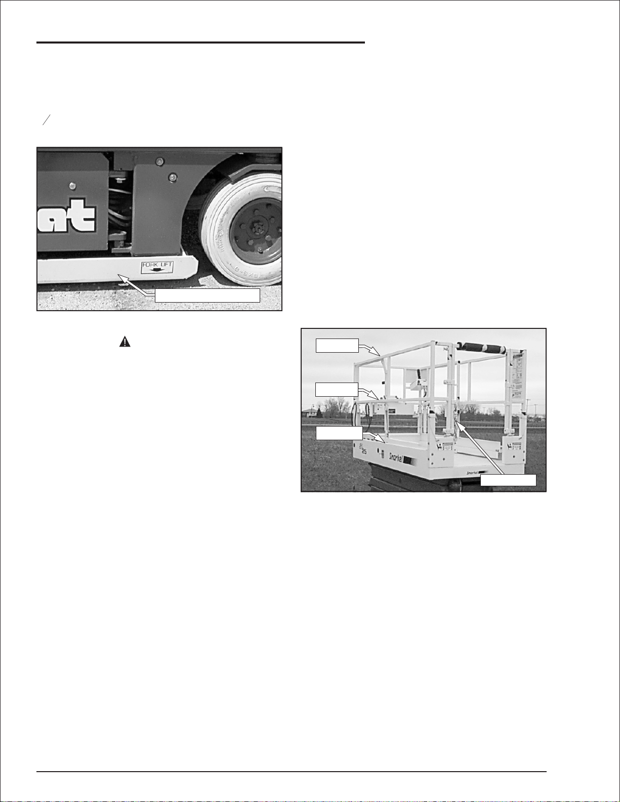
Guardrail System
❑
The guardrail system (refer to Figure 8.20)
includes the top rail, mid rail, toeboards and a
safety chain or optional swinging gate.
Top Rail
Mid Rail
Toeboard
Entry Chain
Figure 8.20—Guardrail System
Inspect all components of the guardrail system.
The rails and toeboards must all be in place and
free of any damage or deformation. Visually
check the rail and toeboard welds for cracks. All
bolts and nuts fastening the guardrails in place
must be present and not show any signs of
looseness.
Latch
Figure 8.21—Platform Extension Latch
Extend the platform and inspect the weldments
for deformation and damage. Visually check the
platform welds for cracks.
Swing-Down Rails
❑
Inspect the snapper and detent pins to make sure
they are in place and are not deformed. There
are two snapper pins and two detent pins at the
front and rear of the platform. The pins must
securely fasten the swing-down rails in the
upright position.
❑
Operating Controls
With the aerial platform stowed, test the
operation of each control from the upper control
station (refer to Figure 8.22).
Inspect the lift up gate at the platform entrance to
be sure it is present and securely fastened to the
rail. The gate must be free of damage and
deformation that may prevent if from functioning
properly. Inspect the detent pins that secure the
gate.
Inspect the safety chain to be sure it is present
and securely fastened to the rail. The chain must
be free of damage and deformation that may
prevent if from functioning properly. Inspect the
hook and eye that secures the chain to the rail.
Inspect the swinging gate to see that it swings
freely, closes firmly, and is not deformed in any
way. Make sure the latch closes and secures the
gate when the gate is closed.
❑
Platform Extension
Inspect the extension latch (refer to Figure 8.21)
to ensure that it properly secures the extended
platform. The latch must also release to extend
the platform. Extend the platform while checking
for proper operation.
Low Voltage
Warning Light
Horn
Button
Interlock
Switch
Steer
Switch
Emergency Stop Button
Battery
Condition
Indicator
Drive/Lift
Selector
Switch
Joystick
Figure 8.22—Upper Controls
From the lower controls, place the battery
disconnect switch in the on position and the
control selector in the up position. Lift the red
emergency stop safety guard up and push the
toggle switch up to turn on the electrical power to
the upper controls.
page 8 - 8 S2545 – 0410002
Page 33

Chapter 8. Prestart Inspection
From the upper controls, test the interlock by
moving the joystick without engaging the interlock
switch. If movement occurs the interlock is not
functioning properly. Do not operate the machine
until the problem is corrected.
Place the drive/lift selector switch in the drive
position and test the operation of the joystick in
both directions. The lift functions should not
operate with the selector in the drive position.
Place the drive/lift selector switch in the lift
position and test the operation of the joystick in
both directions. The drive functions should not
operate with the selector in the lift position.
Emergency Stop
❑
Push the red emergency stop button in to turn off
the electrical power. The upper control functions
should not operate with the emergency stop in
this position.
Lowering Alarm
❑
Raise the platform and then lower it to ensure
that the alarm sounds to warn personnel in the
area that the platform is lowering.
❑ Drive Motion Alarm
Drive in both the forward and reverse directions
to ensure that the alarm sounds to warn
personnel in the area that the aerial platform is in
motion.
❑
Battery Condition Indicator
The optional battery condition indicator (refer to
Figure 8.23) is located on the upper control
panel.
Battery Condition
Indicator
Lanyard Anchors
❑
If the machine is equipped with the optional
lanyard anchors (refer to Figure 8.24), visually
inspect them to make sure they are in place, are
not deformed and are securely fastened to the
platform.
Lanyard Anchor
Figure 8.24—Lanyard Anchors
There is one anchor at the front of the platform
extension and one at the side of the platform.
Horn
❑
If the machine is equipped with the optional horn,
depress the horn button on the left side of the
upper control box (refer to Figure 8.22) to ensure
that it sounds to warn personnel in the area.
❑
Electrical Power Outlet
If the machine is equipped with the optional electrical
power outlet, connect a source of 125 volt AC power
to the power plug. The power plug is located at the
rear of the chassis near the right tire.
Some machines may have an electrical outlet at
the platform, but no power-input connector. In that
case, power is supplied by an optional AC
generator. An external power source is not
required. Plug an electrical tool into the
receptacle and try to operate the tool to verify
proper operation of the outlet.
The outlet may be equipped with a ground fault
circuit interrupter (GFCI). Use the following
procedure to test the GFCI.
1. Push the black test button (refer to Figure 8.25).
Figure 8.23—Battery Condition Indicator
With the machine set up to operate from the
upper controls, check to see that the battery
condition indicator gauge displays a power
reading.
S2545 – 0410002 page 8 - 9
Page 34

Chapter 8. Prestart Inspection
Reset
Button
Figure 8.25—Electrical Power Outlet
2. Plug an electrical tool into the outlet and
verify the power is off.
●
If the power was off, push the reset button
to restore power.
●
If the power was on, repair or replace the
receptacle.
■
Placards and Decals
Inspect all safety and operational placards and
decals. Make certain they are in place, in good
condition, and are legible.
Replace any missing or illegible placards or
decals before operating the aerial platform.
Placard and decal kits are available from Snorkel
dealers.
Figure 8.26 provides the item number, Snorkel
part number, description, and the quantity of
each placard and decal required for standard
aerial platform features.
No Part No Description Req
302326 Platform ratings
1
302985 Ground controls schematic
2
416836 Battery charger 115 volt only
3
300740 Danger towing instructions
4
480658 Danger tipover/electrical hazard
5
300760 Danger tipover hazard
6
451986 Danger do not alter switch
7
300694 ANSI standards
8
0070420 Emergency bleed down valve
9
475596 Caution cylinder disassembly
10
302950 Hydraulic oil level
11
583656 Danger safety prop
12
302844 SL 25 logo
13
560239 Snorkel logo 28 inch orange/black
14
451726 Check battery before charging
15
Test
Button
2
1
1
2
2
2
1
1
1
2
1
1
2
2
1
No Part No Description Req
0070901 Caution serial number
16
300698 Snorkel logo 10 inch orange/black
17
0072545 Emergency stop
18
0074311 Danger cylinder failure (1 per cyl)
19
451776 Hydraulic fluid level
20
302784 Hydraulic schematic
21
300700 Danger shearing/crushing hazard
22
0073585 Made in USA
23
621486 Forklift
24
302782 Ground controls
25
969249 Warning stripes
26
302781 Platform control box top
27
7030002 Lube recommendations
28
302820 Caution - no step
29
Additional decals for fixed rail platforms
300699 Operator's checklist
50
562426 Operating manual enclosed
51
Additional decals for swing-down rail platforms
300699 Operator’s checklist
100
302559 Danger pinch point
101
302562 Pinch point keep clear
102
302567 Danger swing down rails
103
302568 Danger pinch point
104
969249 Warning stripes
105
562426 Operating manual enclosed
106
10
Figure 8.26—Standard Feature
Placards and Decals
Figure 8.27 provides the item number, Snorkel
part number, description, and the quantity of
each placard and decal required for optional
features.
No Part No Description Req
467376 EE logo yellow (EE machines)
A
486006 Factory mutual (EE machines)
B
563066 Horn
C
584196 Danger fire hazard NFPA505
D
584216 Notice use OEM parts
E
0150606 125 volt 15 amp power to platform
F
0152251 EE logo white (EE machines)
G
Figure 8.27—Optional Feature
Placards and Decals
1
2
1
3
1
1
1
2
6
1
1
1
1
1
1
1
1
4
3
3
1
1
1
2
1
1
2
1
2
page 8 - 10 S2545 – 0410002
Page 35

Chapter 8. Prestart Inspection
D
14
13
G
5
14
105
26
3
24
5
15
Left Side
23
23
6
24
26
(Both Sides)
(Inside
1
Platform)
E
13
G
50
19
26
102
262626
10
10
4
Rear
105
(Both Sides)
51
17
F
19
(Inside
1
Platform)
17
29
22
8
B
A
16
Front
2 (Inside Control Panel)
E
19
(1 Per Cyl)
24
6
24
12
24
25
24
9
Right Side
20
4
Top of Chassis
S2545 – 0410002 page 8 - 11
HydraulicTray
21
Page 36

Chapter 8. Prestart Inspection
104
103
101 101
Rear
106
104 (Inside Platform)104 (Inside Platform)
105
103 (Both Sides) 105 (4 Places)
102
105
Main Platform Swing-Down Rails
(4 Places)
Right Side
102
102
(Both Sides)
100
101
101
Inside Front
C
Upper Control Box
102
(2 Places)
Platform Extension Swing-Down Rails
27
18
Right Side
Top of Second
Inner Arm
26
105
7
Outside Front
11
28
Hydraulic Oil
Reservoir
26
Safety Prop
page 8 - 12 S2545 – 0410002
Page 37

Chapter 9. Operation
The aerial platform may be operated from either
the lower or upper controls.
DANGER
The aerial platform is not electrically
insulated. Death or serious injury can result
from contact with, or inadequate clearance
from, an energized conductor. Do not go
closer than the minimum safe approach
distance as defined by ANSI.
Pinch points may exist between moving
components. Death or serious injury can
result from becoming trapped between
components, buildings, structures, or other
obstacles. Make sure there is sufficient
clearance around the machine before moving
the chassis or platform. Allow sufficient room
and time to stop movement to avoid contact
with structures or other hazards.
The aerial platform can tip over if it becomes
unstable. Death or serious injury can result
from a tip-over accident. Operate the aerial
platform on a firm, flat, level surface. Avoid
travel speeds and/or rough terrain that could
cause sudden changes in platform position.
The operator bears ultimate responsibility for
ensuring that the aerial platform is properly set
up for the particular conditions encountered.
■
Preparing for Operation
Make certain the batteries are charged and the
charger is unplugged before operating the aerial
platform. Use the following procedure to prepare
the aerial platform for operation.
1. Close and latch the swing-out battery and
hydraulic component trays.
2. From the lower controls, place the battery
disconnect switch in the on position (refer to
Figure 9.1).
Control Selector
Switch
Battery
Disconnect
Switch
3. Lift the emergency stop guard and push the
toggle switch up.
4. Place the control selector switch in the lower
position.
5. Operate the platform raise/lower switch to
make sure the aerial platform is functioning
properly.
■
Lower Controls
The lower controls override the upper controls.
This means that the lower controls can always be
used to operate the platform regardless of the
position of the upper controls emergency stop
switch.
The lower controls may be used for initial set up
of the aerial platform and raising and lowering the
platform while testing or inspection.
The lower controls (refer to Figure 9.1) are
located on the right side of the chassis. The
following are located at the lower control station.
●
Battery disconnect switch
●
Emergency stop switch
●
Control selector switch
●
Platform raise/lower switch
●
Circuit breaker reset button
●
Low voltage warning light
■
Upper Controls
The upper controls may be used for positioning
the aerial platform and raising and lowering the
platform while on the job.
The upper controls (refer to Figure 9.2) are
located on the right side of the platform. The
following are located at the upper control station.
●
Emergency stop button
●
Drive/lift selector switch
●
Low voltage warning light
●
Joystick to control platform lift, drive, and
steer
The optional horn button and battery condition
indicator gauge may also be located at the upper
control station.
Platform
Raise/Lower
Switch
Emergency
Stop Switch
Figure 9.1—Lower Controls
S2545 – 0410002 page 9 - 1
Page 38

Chapter 9. Operation
Low Voltage
Warning Light
Horn
Button
Interlock
Switch
Steer
Switch
Emergency Stop Button
Figure 9.2—Upper Controls
Before operating from the upper controls,
properly set up the aerial platform as described
under Preparing for Operation. Use the following
procedure to operate the aerial platform from the
upper controls.
1. From the lower controls, place the control
selector switch in the upper position. The
upper controls will not operate while the
control selector is in the lower position.
2. Enter the platform. The top rail at the platform
entrance may be swung upward to load the
platform if necessary. Secure the chain, or
optional swinging gate, and the top rail.
3. Pull the emergency stop button outward.
4. The aerial platform may be positioned and
the platform may be raised and lowered from
the upper controls.
Battery
Condition
Indicator
Drive/Lift
Selector
Switch
Joystick
●
To move forward, slowly push the joystick
forward until the desired speed is reached.
The aerial platform may travel at three
different speeds depending on how far
forward the joystick is moved. The three
speed ranges are separated by detents
that can be felt as the joystick is moved
from neutral.
●
To move backward, slowly pull the joystick
backward. There is only one reverse
speed.
Drive Speeds
◆
The aerial platform can travel at three different
drive speeds. Drive speed ranges are interlocked
through a limit switch that senses scissors arm
position. When the platform is elevated below
approximately seven feet, the aerial platform may
be driven forward or backward at three different
speeds. Above seven feet of elevation, the two
fastest speeds are locked out and only the
slowest drive speed will work.
DANGER
The potential for an accident increases when
safety devices do not function properly. Death
or serious injury can result from such
accidents. Do not alter, disable, or override
any safety device.
Do not use the aerial platform if it drives faster
than ½ mile per hour (25′ in 30 seconds) when
elevated above 7′ even if the joystick is in the mid
or high speed position.
❑
Driving
DANGER
The aerial platform can tip over if it becomes
unstable. Death or serious injury can result
from a tip-over accident. Do not drive an
elevated aerial platform on soft, uneven, or
sloping surfaces. Do not drive a fully stowed
machine on grades that exceed 25 percent.
A fully stowed machine may be operated on
grades up to 25 percent. A grade of 25 percent is
a30″ (76.2 cm) vertical rise in 10′ (3.05 m)
horizontal length. Use the following procedure to
drive the aerial platform using the upper controls.
1. Place the drive/lift selector switch (refer to
Figure 9.2) in the drive position.
2. Squeeze and hold the interlock switch
against the joystick.
◆
Drive/Lift Level Sensor Interlock
When the platform is elevated above approximately
seven feet, lift and drive functions are interlocked
through a level sensor system. If the chassis is
tilted more than two degrees side-to-side, or four
degrees front-to-rear, platform raise and drive
functions are disabled and an alarm sounds
when those controls are activated.
If the drive/lift level sensor interlock shuts off the
platform raise and drive functions, lower the
platform and drive to a level surface.
Platform raise and drive functions may also be
disabled by the pothole protection interlock.
❑
Steering
The steer control switch is located on the joystick
(refer to Figure 9.2). Use the following procedure to
steer the aerial platform using the upper controls.
1. Squeeze and hold the interlock switch
against the joystick.
page 9 - 2 S2545 – 0410002
Page 39

Chapter 9. Operation
●
To turn to the left, tap lightly on the left side
of the steer switch.
●
To turn to the right, tap lightly on the right
side of the steer switch.
NOTE
Holding the steer switch down too long may result
in a sharp turn. This is especially true when
driving and steering at the same time. It may be
easier to turn the wheels in small increments
using a series of quick taps on the steer switch.
2. Reverse the steer control direction after
completing a turn to return to a straight line
travel. The steering wheels are not
self-centering.
Platform
❑
The platform rated work load is the total weight of
the personnel and equipment that may be lifted in
the platform. The work loads are stated on the
platform rating placard mounted on the toeboard
at the front of the platform.
●
To raise the platform, slowly push the
joystick forward until the desired speed is
reached. The platform can be raised at
three different speeds depending on how
far forward the joystick is moved. The three
speed ranges are separated by detents
that can be felt as the joystick is moved
from neutral.
●
To lower the platform, slowly pull the
joystick backward. There is only one
lowering speed.
Extending
◆
The platform can be extended and securely
locked into seven different positions. Use the
following procedure to extend or retract the
platform.
1. Stand on the non-extendible part of the
platform floor, facing the front of the platform.
2. Squeeze and hold the trigger (refer to Figure
9.3) while pushing or pulling on the
retractable rails.
DANGER
The aerial platform can tip over if it becomes
unstable. Death or serious injury can result
from a tip-over accident. Do not exceed the
capacity values indicated on the platform
rating placard.
Capacity values indicate the rated lifting capacity
and do not indicate aerial platform stability.
Use care when entering and exiting the platform
to avoid slipping and/or falling. Securely close the
safety chain or optional swinging gate when the
platform is occupied.
DANGER
The potential for an accident increases when
the swing-down rails are lowered. Death or
serious injury can result from such accidents.
Do not elevate the platform with the
swing-down rails lowered.
Be sure the swing-down rails are up, the detent
pins are engaged, and the snapper pins are
installed at each corner of the platform, except
when passing through a low clearance area with
the platform completely lowered.
Trigger
Figure 9.3—Platform Extend Trigger
3. Release the trigger when the platform is at
the desired position.
4. Try to move the rails back and forth to make
sure they are locked in position.
◆
Raising and Lowering
1. Place the drive/lift selector switch (refer to
Figure 9.2) in the lift position.
2. Squeeze and hold the interlock switch
against the joystick.
S2545 – 0410002 page 9 - 3
Page 40

Chapter 9. Operation
CAUTIO
CAUTIO
Lift-Up Entry Gate
◆
The platform entrance has a lift-up entry gate
(refer to Figure 9.4) to load large objects in the
platform.
Lift-Up Gate
Snapper Pins
Detent Pins
Detent Pins
Figure 9.4—Lift-Up Gate
To raise the gate, pull the detent pins outward
and then pull up on the top rail. When the gate is
fully raised the detent pins will engage to hold the
gate up.
Swing-Down Rails
◆
The platform rails may be lowered 10
1
″ to fit the
2
machine under low height obstructions.
DANGER
The potential for an accident increases when
the swing-down rails are lowered. Death or
serious injury can result from such accidents.
Do not elevate the platform with the
swing-down rails lowered.
N
The rails are free to move downward after
pulling backward on them. Improper lifting
can cause personal injury. Be prepared to
hold the weight of the rails (approximately 20
pounds) before beginning to lower them to
the platform.
Figure 9.5—Platform Extension Release Pins
N
The rails are free to move when the foot is
completely off its rest. Uncontrolled movement
of the rails can cause personal injury. Do not
move the foot more than a quarter inch (6 mm)
to offset the detent pin and the hole.
3. Pull both detent pins up. With both pins up,
pull back on the guardrail about ¼" (6 mm) or
just enough to offset the pins from the holes.
4. Stand facing the front of the platform, grasp
the handles and pull backward.
5. Lower the guardrails to the platform floor.
Make sure the cables for the upper controls
and the electrical outlet are not pinched.
To lower the main platform rails, use the following
procedure.
1. Remove both snapper pins at the rear of the
platform (refer to Figure 9.6).
Snapper Pins
The platform extension and the main platform rails
must be lowered separately. Use the following
procedure to lower the platform extension rails.
Detent Pins
1. Enter the platform and close the entry chain
or swinging gate.
2. Remove both snapper pins at the front of the
platform (refer to Figure 9.5).
page 9 - 4 S2545 – 0410002
Figure 9.6—Main Platform Release Pins
Page 41

CAUTIO
N
The rails are free to move when the foot is
completely off its rest. Uncontrolled movement
of the rails can cause personal injury. Do not
move the foot more than a quarter inch (6 mm)
to offset the detent pin and the hole.
2. Pull one of the detent pins down and pull
back on the guardrail about
enough to offset the pin from the hole.
Repeat this step for the detent pin on the
other side of the entrance.
1
″ (6 mm) or just
4
Chapter 9. Operation
This system operates automatically to stop and
hold the aerial platform when the drive controls
are released or power is interrupted. Manually
disengage the brakes before towing or winching
the aerial platform as described under Towing in
Chapter 11—Emergency Operation.
■
Swing-Out Trays
Batteries and hydraulic components are enclosed
in swing-out trays (refer to Figure 9.8) on each
side of the chassis.
3. Stand facing the rear of the platform, grasp
the top rail and pull backward.
4. Lower the guardrails to the platform floor.
Use the following procedure to raise the extension
and main platform rails.
1. Carefully lift upward on the rails.
2. Push the rails forward firmly to automatically
seat the detent pins into their holes.
3. Check the detent pins to make sure they are
properly seated.
4. Install the snapper pins with the head to the
outside of the platform.
■
Brakes
Each rear wheel is equipped with a mechanical
spring-applied, hydraulically released parking
brake. When the drive control is in neutral, a
spring-activated pin protrudes through an
opening in the brake disc to prevent movement
(refer to Figure 9.7). A flow control valve slows
the pin movement to allow the aerial platform to
stop before the parking brakes engage.
Latch
Tray
Figure 9.8—Swing-Out Tray
The tray on the right side of the chassis contains
the electrical panel for the lower controls, the
hydraulic directional control valve, the
free-wheeling valve, reservoir, pump, and the
hydraulic fluid filter. The tray on the left side
contains the four batteries and the charger.
DANGER
The aerial platform can tip over if it becomes
unstable. Death or serious injury can result
from a tip-over accident. Do not open the
swing-out trays when the platform is raised
more than nine feet.
To open a tray, pull up on the latch, step down on
Brake
Engaged
Cam
the pothole protector skid, and swing the tray
open.
If the platform is raised to approximately 24″ and
the pothole protection skids are down, the trays will
swing out without lowering the skids.
Figure 9.7—Mechanical Brake
S2545 – 0410002 page 9 - 5
Page 42

Chapter 9. Operation
■
Electrical Power Outlet
The optional electrical box has 2, 3-prong, 125
volt AC electrical connectors (refer to Figure 9.9).
Their combined output is limited by a 20 amp
circuit breaker.
Figure 9.9—Electrical Power Outlet
The power-input connector for the electrical outlet
is located at the rear of the chassis near the right
tire (refer to Figure 9.10). Plug a source of power
into the power-input connector when electrical
power is required at the platform.
Power-Input Connector
Figure 9.10—Power-Input Connector
Unplug the source of power before moving the
aerial platform.
Some machines may have an electrical outlet at
the platform, but no power-input connector. In that
case, power is supplied by an optional AC
generator. An external power source is not
required.
page 9 - 6 S2545 – 0410002
Page 43

Chapter 10. Stowing and Transporting
To prevent unauthorized use and damage,
properly stow the aerial platform at the end of
each work day. It must also be properly stowed
while transporting.
■
Stowing
Use the following procedure to properly stow the
aerial platform.
1. Retract the platform extension.
2. Fully lower the platform.
3. Close the emergency stop switch cover to
activate the emergency stop switch.
4. Turn the battery disconnect switch off.
5. Padlock the battery disconnect switch.
■
Transporting
The aerial platform may be moved on a transport
vehicle. Depending on the particular situation, the
aerial platform may be lifted with a forklift,
winched, driven, or hoisted onto a vehicle such
as a truck or trailer. Lifting with a forklift is the
preferred method.
DANGER
The aerial platform can tip over if it becomes
unstable. Death or serious injury can result
from a tip-over accident. Do not drive on
ramps that exceed 25 percent grade, or where
conditions of the ramp could cause driving to
be hazardous.
The user assumes all responsibility for choosing
the proper method of transportation, and the
proper selection and use of transportation and
tie-down devices, making sure the equipment
used is capable of supporting the weight of the
aerial platform and that all manufacturer’s
instructions and warnings, regulations and safety
rules of their employer, the DOT and/or any other
state or federal law are followed.
Winching
❑
Use the following procedure to winch the aerial
platform onto the transport vehicle.
1. Locate the transport vehicle so the aerial
platform will not roll forward after it is loaded.
2. Remove any unnecessary tools, materials, or
other loose objects from the platform.
3. From the upper controls, center the aerial
platform with the loading ramps and transport
vehicle bed. Make sure that the steering
wheels are straight.
4. Properly stow the aerial platform.
3
5. Use a
″ wrench to rotate each brake release
4
cam 90° (refer to Figure 10.1). Rotate the cam
on the right brake cylinder counterclockwise
and the one on the left brake cylinder
clockwise. This will retract the brake pins from
the wheel lugs releasing the brakes. Remove
the wrench.
Use a winch to load and unload the aerial
platform on ramps that exceed 25 percent grade.
A 25 percent grade is a 30″ (76.2 cm) vertical
rise in 10′ (3.05 m) horizontal length. A winch
may also be used when poor traction, uneven
surfaces, or stepped ramp transitions make
driving hazardous.
Drive the aerial platform onto the transport
vehicle if a winch is not available and the ramp
incline is within the 20 percent grade capability of
the aerial platform.
The aerial platform weighs approximately 4,700
pounds. The equipment used to load, unload, and
transport the aerial platform must have adequate
capacity.
Figure 10.1—Brake Release Cam
6. Unlatch and swing out the hydraulic tray. The
free-wheeling valve is located on the
hydraulic manifold (refer to Figure 10.2). Turn
the free-wheeling valve counterclockwise to a
fully opened position.
S2545 – 0410002 page 10 - 1
Page 44

Chapter 10. Stowing and Transporting
Free-Wheeling
Val ve
Figure 10.2—Free-Wheeling Valve
7. Attach the winch to the tie-down lugs (refer to
Figure 10.3) on the front of the chassis.
Lift Lug
5. Place the joystick in speed two for climbing a
ramp or speed one for descending a ramp.
6. Drive the aerial platform on or off the
transport vehicle in a straight line through the
grade transitions with minimal turning.
Hoisting
❑
Use the following procedure to hoist the aerial
platform onto the transport vehicle.
1. Inspect the lift lugs to make sure they are free
of cracks, rust, and are in good condition. There
are two lugs on the rear of chassis and two on
the front of chassis (refer to figure 10.3).
2. Remove all personnel, tools, materials, or
other loose objects from the platform.
3. Connect chains or straps to create a four
point lift using the tie-down lugs.
4. Use a spreader bar of sufficient length to
keep the chains or straps from contacting the
upper structure of the aerial platform.
Tie-Down Lug
Figure 10.3—Tie-Down Lugs
8. Use the winch to position the aerial platform
on the transport vehicle.
9. Close the free-wheeling valve.
10. Manually reset the parking brakes using a
wrench or drive the aerial platform to reset them.
❑
Driving
Use the following procedure to drive the aerial
platform onto the transport vehicle.
1. Locate the transport vehicle so the aerial
platform will not roll forward after it is loaded.
2. Remove any unnecessary tools, materials, or
other loose objects from the platform.
3. Fully lower the platform and retract the
platform extension.
5. Adjust the length of each chain or strap so
the aerial platform remains level when raised
off the ground.
6. Use the hoist to carefully raise and position
the aerial platform onto the transport vehicle.
❑
Lifting With a Forklift
Use the following procedure to lift the aerial
platform with a forklift.
1. Properly stow the aerial platform.
2. Remove all personnel, tools, materials, or
other loose objects from the platform.
3. Insert the forklift forks into the pockets (refer to
Figure 10.4) or at the designated points under
the pothole protector skids to lift the machine.
Forklift Pocket
4. From the upper controls, center the aerial
platform with the loading ramps and transport
vehicle bed. Make sure that the steering
wheels are straight.
page 10 - 2 S2545 – 0410002
Figure 10.4—Forklift Pockets
Page 45

4. Do not raise the aerial platform higher than
CAUTIO
necessary to transport it. Drive the forklift slowly
and carefully when transporting the platform.
Securing for Transport
❑
Use the following procedure to secure the aerial
platform on the transport vehicle.
1. Properly stow the aerial platform.
2. Remove all personnel, tools, materials, or
other loose objects from the platform.
3. Chock the wheels.
4. Place four inch blocks under the front ends of
the pothole protection skids to limit excessive
loading on the front drive wheel bearings.
N
Ratchets, winches, and come-alongs can
produce enough force to damage machine
components. Do not over tighten the straps or
chains when securing the aerial platform to
the transport vehicle.
Chapter 10. Stowing and Transporting
5. Use chains or straps to securely fasten the
aerial platform to the transport vehicle using the
front and rear tie-down lugs as attachment
points. Proper tie-down and hauling is the
responsibility of the carrier.
S2545 – 0410002 page 10 - 3
Page 46

Chapter 11. Emergency Operation
If the aerial platform cannot be operated due to a
loss of hydraulic power, such as motor or pump
failure, the platform lift cylinder and drive wheels
may be operated manually. Refer to the
Emergency Lowering or Towing section for the
appropriate procedure.
■
Emergency Lowering
Use the following procedure to manually lower
the platform.
1. Retract the platform extension, if possible.
2. Locate the emergency lowering handle at the
front of the aerial platform (refer to Figure 11.1).
Emergency
Lowering Handle
and the one on the left brake cylinder clockwise.
Remove the wrench.
Figure 11.2—Brake Release Cam
4. Unlatch and swing out the hydraulic tray. The
free-wheeling valve is located on the
hydraulic manifold (refer to Figure 11.3). Turn
the free-wheeling valve counterclockwise to a
fully opened position. Close the tray.
Figure 11.1—Emergency Lowering Handle
3. Make sure there is nothing in the way to
obstruct the platform when it lowers.
DANGER
Pinch points exist on the scissors structure.
Death or serious injury can result from
becoming trapped within the scissors
structure. Make sure all personnel stand clear
while lowering the platform with the
emergency lowering handle.
4. Pull the handle outward to lower the platform.
5. Release the handle to stop.
■
Towing
The aerial platform may be pushed or pulled after
disengaging the brakes. Use the following
procedure to manually disengage the brakes.
1. Restrain the aerial platform if it is not on a
level surface to prevent movement when the
brakes are released.
2. Turn the battery disconnect switch off.
3
3. Use a
cam 90° (refer to Figure 11.2). Rotate the cam
on the right brake cylinder counterclockwise
″ wrench to rotate each brake release
4
Free-Wheeling
Val ve
Figure 11.3—Free-Wheeling Valve
5. Do not exceed two miles per hour when
towing.
DANGER
The aerial platform is free to move when the
brakes and free-wheeling valve are disabled.
Death or serious injury can result. Close the
free-wheeling valve and reset the brakes
before operating the aerial platform.
6. Close the free-wheeling valve after moving
the aerial platform.
7. Manually reset the parking brakes using a
wrench or drive the aerial platform to reset
them.
8. Verify that the brakes reset properly.
S2545 – 0410002 page 11 - 1
Page 47

Chapter 12. Troubleshooting
The chart below lists situations where machine operation may be interrupted. If the problem cannot be
corrected with the action listed, stow the machine and remove it from service. Repairs must be made
by qualified maintenance personnel.
■
Troubleshooting Chart
Symptom Possible Cause Corrective Action
All functions stop working. Motor or pump failure.
Manually stow the machine.
Low fluid level in reservoir.
Circuit breaker on the lower control
panel has tripped.
Electrical system malfunction.
Platform will not raise or
lower from lower controls.
Upper controls will
not work.
Platform will not raise or
lower from upper controls.
Platform will not raise and
alarm is sounding.
Platform drifts down. Emergency lowering handle not
Control selector switch in the upper
control position.
Battery disconnect switch turned off.
Emergency stop switch in the off
position.
Emergency lowering handle not
properly disengaged.
Control selector switch in the lower
control position.
Battery disconnect switch turned off.
Emergency stop button pushed inward
to the off position.
Drive/lift selector is in the drive position.
Emergency lowering handle not
properly disengaged.
Machine is not on a level surface. Lower the platform and drive to a level
properly disengaged.
Check fluid level. Add correct type of
fluid if necessary.
Press the circuit breaker reset button.
Manually stow the machine.
Place switch in the lower control
position.
Place switch in the on position.
Raise safety guard and place switch in
the on position.
Ensure handle returns to normal
operating position.
Place switch in the upper control
position.
Place switch in the on position.
Pull the emergency stop button outward
to the on position.
Place switch in the lift position.
Ensure handle returns to normal
operating position.
surface.
Ensure handle returns to normal
operating position.
Hydraulic system malfunction.
Platform will not lower. Safety prop in place. Stow the safety prop.
Platform will not extend. Latch not fully releasing. Fully engage the platform extend trigger
Drive functions
don’t work.
S2545 – 0410002 page 12 - 1
Drive/lift selector is in the lift position.
Machine is not on a level surface or too
steep a grade.
Free-wheeling valve is open.
Load capacity exceeded.
Low hydraulic system pressure.
Manually stow the machine.
to release the latch before extending
the platform.
Place the switch in the drive position.
Lower the platform and drive to a level
surface.
Fully close the free-wheeling valve.
Remove load from platform. Refer to
platform capacity placard for maximum
capacity.
Manually stow the machine.
Page 48

Chapter 12. Troubleshooting
Symptom Possible Cause Corrective Action
Only slow drive
speed works.
Machine will not steer. Joystick interlock switch not engaged. Engage the interlock switch before
Low voltage warning
light on.
Electrical outlet does not
work.
Platform elevated above seven feet. Lower platform to drive machine at mid
and high speed.
operating the steer switch.
Low battery voltage. Lower the platform, drive to recharging
area and charge the batteries.
Power supply not plugged in.
Plug in power supply at outlet at rear of
chassis.
GFCI is tripped.
Wheels won’t turn when
winching or pushing.
Circuit breaker will not
reset.
Brakes don’t work. Brake pins not engaged. Manually release brake cams with a
Swing-out tray will not
open or close.
Ammeter does not
indicate a reading when
charging the batteries.
Severe hydraulic leak. Failure of hose, tube, fitting, seal, etc. Manually stow the machine.
Brake pins engaged.
Free-wheeling valve closed.
Electrical system malfunction. Manually stow the machine.
Pothole protector skid in the way. Step down on skid and swing tray out.
No source of power.
Circuit breaker on the lower control
panel has tripped.
Charger power fuse is blown.
Push reset button on outlet.
Rotate brake release cams to
disengage brakes.
Fully open free-wheeling valve.
wrench or drive the machine to reset
the brakes.
Make sure power source is plugged in
and turned on.
Press the circuit breaker reset button.
Manually stow the machine.
page 12 - 2 S2545 – 0410002
Page 49

Appendix A. Glossary
aerial platform—a mobile device that has an
adjustable position platform, supported from
ground level by a structure.
authorized personnel—personnel approved as
assigned to perform specific duties at a specific
location.
base—the relevant contact points of the aerial
platform that form the stability support (e.g.
wheels, casters, outriggers, stabilizers).
battery tray—a swing-out compartment that
holds the batteries and battery charger.
chassis—the integral part of the aerial platform
that provides mobility and support for the scissors
structure.
fall restraint—a system that is used while
working on a boom lift within the boundaries of
platform guardrails to provide restraint from being
projected upward from the platform. This system
includes a harness or belt, lanyard, and a lanyard
anchor. Although federal OSHA, ANSI, and
Snorkel do not require the use of fall restraint on
scissors lift aerial platforms, local, state, or
employer rules may require their use.
free-wheeling valve—a needle valve that when
adjusted open allows hydraulic fluid to flow
through the wheel drive motors. This allows the
aerial platform to be pushed or towed without
damage to the drive motors.
gradeability—the maximum slope that the aerial
platform is capable of travel.
local concentrated pressure—floor loading
pressure of an aerial platform based on the
maximum load exerted on one tire and the
calculated footprint area of the tire. This value is
of concern when the floor surface, on which the
machine is being used, needs to be protected
from indentations or breakage due to high
pressure being exerted on a relatively small area.
lower controls—the controls located at ground
level for operating some or all of the functions of
the aerial platform.
maximum travel height—the maximum platform
height or the most adverse configuration(s) with
respect to stability in which travel is permitted by
the manufacturer.
Minimum Safe Approach Distance—the
minimum safe distance that electrical conductors
may be approached when using the aerial
platform. Also called M.S.A.D.
operation—the performance of any aerial
platform functions within the scope of its
specifications and in accordance with the
manufacturer’s instruction, the users work rules,
and all applicable governmental regulations.
overall uniform pressure—floor loading
pressure of an aerial platform based on the gross
vehicle weight and the rated work load. This
value may be of concern when the aerial platform
is used on a beam supported floor or surface.
The maximum allowable floor loading pressure is
determined its architect or engineer.
ground fault circuit interrupter—a fast-acting
circuit breaker that opens to stop electrical circuit
flow if it senses a very small current leakage to
ground. Also called GFCI. The GFCI is used to
protect personnel against a potential shock
hazard from defective electrical tools or wiring.
guardrail system—a vertical barrier around the
platform to prevent personnel from falling.
hazardous location—any location that contains,
or has the potential to contain, an explosive or
flammable atmosphere as defined by ANSI/NFPA
505.
hydraulic tray—a swing-out compartment that
holds the electrical panel for the lower controls,
the hydraulic directional control valve, the
free-wheeling valve, and the hydraulic fluid
reservoir, pump and filter.
personal fall arrest system—a fall protection
system that is used while working on an
unprotected edge (such as a roof top with no
guardrail). This system includes a harness,
lanyard or other connecting device, a fall arrestor,
an energy absorber or decelerator, an anchorage
connector, and a secure anchorage such as a
building beam, girders or columns. An aerial
platform is not a fall arrest anchorage.
platform—the portion of an aerial platform
intended to be occupied by personnel with their
tools and materials.
platform height—the vertical distance measured
from the floor of the platform to the surface upon
which the chassis is being supported.
pothole protection—a mechanical system
intended to reduce the likelihood of aerial
platform tip-over.
qualified person—a person, who by reason of
knowledge, experience, or training is familiar with
the operation to be performed and the hazards
involved.
S2545 – 0410002
Page 50

Glossary
rated work load—the designed carrying capacity
of the aerial platform as specified by the
manufacturer.
scissors structure—the mechanisms used to
position the platform relative to the aerial platform
chassis.
stow—to place a component, such as the
platform, in its rest position.
unrestricted rated work load—the maximum
designed carrying capacity of the aerial platform
allowed by the manufacturer in all operating
configurations.
upper controls—the controls located on or
beside the platform used for operating some or
all of the functions of the aerial platform.
S2545 – 0410002
Page 51

Index
A
AC generator, 1-1
aerial platform drive and speed, 7-2
aerial platform stability, 8-4
aerial platform steering, 7-2
American National Standards Institute (ANSI),
1-1
ammeter, 5-1, 6-1
B
batteries, 8-2
battery charger, 6-1
battery condition indicator, 1-1, 5-1, 7-3, 8-9,
9-1
battery disconnect switch, 7-1, 9-1
battery fluid level, 8-2
battery terminals, 8-2
cable ends, 8-2
brakes, 9-4
brake disc, 9-5
brake pin, 9-5
disengaging, 9-5
release cam, 8-4
C
cables and wiring harness, 8-3
Canadian Standards Association (CSA), 1-1
circuit breaker reset button, 7-1, 9-1
component identification, 2-1
control selector switch, 7-1, 9-1
D
DC electrical motor, 8-3
drive motion alarm, 4-1, 8-9
drive speeds, 9-2
drive/lift level sensor interlock, 4-2, 9-2
drive/lift pothole protector interlock, 4-2
drive/lift selector switch, 7-2, 9-1
driving, 9-2, 10-2
E
electrical overload, 7-1
electrical power, 1-1
electrical power outlet, 4-4, 8-9, 9-6
power-input connector, 9-6
electrical system, 2-2, 3-3, 8-2
electrocution hazards, 3-1
emergency lowering, 8-6, 11-1
lowering handle, 4-2, 8-6, 11-1
emergency stop, 7-1, 8-9
button, 7-2
controls, 4-1
switch, 7-1, 8-5
entering or exiting the platform, 3-2
F
fasteners, 8-7
flashing light, 1-1, 4-4, 8-7
free-wheeling valve, 8-4, 11-1
closing, 8-4
G
general maintenance, 6-1
general specifications, 2-2
gradeability, 2-2
25 percent grade, 9-2
ground clearance, 2-2, 4-2, 8-5
ground fault circuit interrupter, 8-9
reset button, 8-10
test button, 8-9
ground strap, 8-4
guardrail system, 8-8
guardrails, 4-2
mid rail, 8-8
safety chain, 8-8
swinging gate, 8-8
toeboards, 8-8
top rail, 8-8
H
hoisting, 10-2
horn, 1-1, 4-4, 8-9
button, 7-3, 9-1
hoses, tubes, and fittings, 8-3
routing, 8-3
hour meter, 5-1
hydraulic system, 3-3, 8-3
fluid level, 8-3
fluid recommended, 2-2
hydraulic pump, 8-3
I
inspection, 1-2
interlock, 8-9, 9-2
J
joystick
lift and steer, 7-2, 9-1
S2545 – 0410002
Page 52

Index
L
lanyard anchors, 1-1, 4-4, 8-9
level ground, 3-3
level sensor interlock, 8-6
lifting with a forklift, 10-2
loss of hydraulic power, 11-1
low voltage warning light, 7-1, 7-2, 7-3, 9-1
lower control station, 8-4
lower controls, 4-1, 7-1, 9-1
lowering alarm, 4-1, 8-5, 8-9
M
maintenance, 1-2
manual of responsibilities, 1-2
minimum safe approach distance, 3-1
O
Occupational Safety and Health Administration
(OSHA), 1-1
operation, 3-2
operator’s manual, 8-2
manual holder, 8-2
options, 1-1
overall height, stowed, 2-2
overall length, stowed, 2-2
overall width, 2-2
P
parking brakes, 8-4
placards and decals, 3-3, 8-10
cleaning, 3-3
Snorkel part number, 8-10
platform, 9-3
raising and lowering, 9-3
platform capacity, 3-3
platform extend trigger, 9-3
platform extension, 8-8
platform raise/lower and speed, 7-2
platform raise/lower switch, 7-1, 9-1
positioning safety prop, 4-3
pothole protector
interlock, 8-5
interlock test, 8-5
skids, 4-2
preparing for operation, 9-1, 9-2
prestart inspection, 3-2
prestart inspection table, 8-1
reservoir, 8-3
capacity, 2-2
fluid level, 8-3
level indicator, 8-3
S
safety alerts, 1-1
safety prop, 4-3
scissors arm rollers, 8-7
securing for transport, 10-3
slide blocks, 8-7
steering, 9-2
stowing safety prop, 4-3
stowing work platform, 10-1
structures, 8-7
mechanical, 8-7
weldments, 8-7
swinging gate, 1-1, 4-2
swing-out tray, 8-2, 9-5
latch keeper, 9-5
T
tie-down lugs, 10-2
tip-over and falling hazards, 3-3
tires, 2-2
toeboard height, 2-2
towing, 11-1
training, 1-1
transporting work platform, 10-1
turning radius, 2-2
U
upper control station, 8-8
upper controls, 4-1, 7-2, 9-1
W
wheel lug nuts, 8-4
winching work platform, 10-1
windy or gusty conditions, 3-3
work place inspection and practices, 3-2
working height, 2-2
R
rated work load, 9-3
S2545 – 0410002
Page 53

LIMITED WARRANTY
Snorkel warrants each new machine manufactured and sold by it to be free from defects in material and workmanship for a
period of one (1) year fromdate of delivery to a Customer or for one year after themachine has been placed in first service in a
Dealer rental fleet, whichever comes first.Any part or parts which, upon examination by the Snorkel Service Department, are
found to be defective, will be replaced or repaired, at the sole discretion of Snorkel, through its local Authorized Dealer at no
charge.
Snorkel further warrants the structural components; specifically, the mainframe chassis, turntable, booms and scissor arms,
of each new machine manufactured by it to be free from defects in material and workmanship for an additional period of four
(4) years. Any such part or parts which, upon examination by the Snorkel Service Department, are found to be defective will
be replaced or repaired by Snorkelthrough its local Authorized Dealer atno charge;however,any labor charges incurred as a
result of such replacement or repair will be the responsibility of the Customer or Dealer.
The Snorkel Service Department must be notified within forty-eight (48) hours of any possible warranty situation during the
applicable warranty period. Personnel performing warranty repair or replacement must obtain specific approval by Snorkel
Service Department prior to performing any warranty repair or replacement.
Customer and Dealer shall not be entitled to the benefits of this warranty and Snorkel shall have no obligations hereunder
unless the “Pre-Delivery and Inspection Report” has been properly completed and returned to the Snorkel Service
Department within ten (10) days after delivery of the Snorkel product to Customer or Dealer’s rental fleet. Snorkel must be
notified, in writing, within ten (10) days, of any machine sold to a Customer from a Dealer’s rental fleet during the warranty
period.
At the direction of the Snorkel Service Department, any component part(s) of Snorkel products to be replaced or repaired
under this warranty program must be returned freight prepaid to the Snorkel Service Department for inspection. All warranty
replacement parts will be shipped freight prepaid (standard ground) from the Snorkel Service Department or from Snorkel’s
Vendor to Dealer or Customer.
REPLACEMENT PARTS WARRANTY
Any replacement or service part made or sold by Snorkel is not subject to the preceding Limited Warranty beyond the
normal warranty period of the machine upon which the part was installed.
THIS WARRANTY EXCLUDES AND SNORKEL DOES NOT WARRANT:
1. Engines, motors, tires and batteries which are manufactured by suppliers to Snorkel, who furnish their own warranty.
Snorkel will, however, to the extent permitted, pass through any such warranty protection to the Customer or Dealer.
2. Any Snorkel product which has been modified or altered outside Snorkel’s factory without Snorkel’s written approval, if
such modification or alteration, in the sole judgment of Snorkel’s Engineering and/or Service Departments, adversely
affects the stability, reliability or service life of the Snorkel product or any component thereof.
3. Any Snorkel product which has been subject to misuse, improper maintenance or accident. “Misuse” includes but is not
limited to operation beyond the factory-rated load capacity and speeds. “Improper maintenance” includes but is not
limited to failureto follow the recommendations contained in the Snorkel Operation,Maintenance, Repair Parts Manuals.
Snorkel is not responsible for normal maintenance, service adjustments and replacements, including but not limited to
hydraulic fluid, filters and lubrication.
4. Normal wear of any Snorkel component part(s). Normal wear of component parts may vary with the type application or
type of environment in which the machine may be used; such as, but not limited to sandblasting applications.
5. Any Snorkel product that has come in direct contact with any chemical or abrasive material.
6. Incidental or consequential expenses, losses, or damages related to any part or equipment failure, including but not
limited to freight cost to transport the machine to a repair facility, downtime of the machine, lost time for workers, lost
orders, lost rental revenue, lost profits or increased cost.
This warranty is expressly in lieu of all other warranties, representations or liabilities of Snorkel, either expressed or implied,
unless otherwise amended in writing by Snorkel’s President, Vice President-Engineering, Vice President-Sales or Vice
President-Marketing.
SNORKEL MAKES NO WARRANTIES WHICH EXTEND BEYOND THE DESCRIPTION OF THIS LIMITED WARRANTY.
SNORKEL MAKES NO IMPLIED WARRANTY OF MERCHANTABILITY OR FITNESS FOR A PARTICULAR PURPOSE
AND DISCLAIMS ALL LIABILITY FOR INCIDENTAL OR CONSEQUENTIAL DAMAGES, INCLUDING BUT NOT
LIMITED TO INJURY TO PERSONS OR PROPERTY.
The Customer shall make all warranty claims through its local Authorized Dealer and should contact the Dealer from whom
the Snorkel product was purchased for warranty service. Or, if unable to contact the Dealer, contact the Snorkel Service
Department for further assistance.
Effective July 1995
© Snorkel – all rights reserved
Printed in USA
 Loading...