

Page 1

P/N 0163187
February, 2001
Page 2

LIMITED WARRANTY
Snorkel warrants each new machine manufactured and sold by it to be free from defects in material and workmanship for a
period of one (1) year from date of delivery to a Customer or for one year after the machine has been placed in first service in a
Dealer rental fleet, whichever comes first. Any part or parts which, upon examination by the Snorkel Service Department, are
found to be defective, will be replaced or repaired, at the sole discretion of Snorkel, through its local Authorized Dealer at no
charge.
Snorkel further warrants the structural components;specifically, the mainframe chassis, turntable, booms and scissor arms,
of each new machine manufactured by it to be free from defects in material and workmanship for an additional period of four
(4) years. Any such part or parts which, upon examination by the Snorkel Service Department, are found to be defective will
be replaced or repaired by Snorkel through its local Authorized Dealer at no charge; however, any labor charges incurredas a
result of such replacement or repair will be the responsibility of the Customer or Dealer.
The Snorkel Service Department must be notified within forty-eight (48) hours of any possible warranty situation during the
applicable warranty period. Personnel performing warranty repair or replacement must obtain specific approval by Snorkel
Service Department prior to performing any warranty repair or replacement.
Customer and Dealer shall not be entitled to the benefits of this warranty and Snorkel shall have no obligations hereunder
unless the “Pre-Delivery and Inspection Report” has been properly completed and returned to the Snorkel Service
Department within ten (10) days after delivery of the Snorkel product to Customer or Dealer’s rental fleet. Snorkel must be
notified, in writing, within ten (10) days, of any machine sold to a Customer from a Dealer’s rental fleet during the warranty
period.
At the direction of the Snorkel Service Department, any component part(s) of Snorkel products to be replaced or repaired
under this warranty program must be returned freight prepaid to the Snorkel Service Department for inspection. All warranty
replacement parts will be shipped freight prepaid (standard ground) from the Snorkel Service Department or from Snorkel’s
Vendor to Dealer or Customer.
REPLACEMENT PARTS WARRANTY
Any replacement or service part made or sold by Snorkel is not subject to the preceding Limited Warranty beyond the
normal warranty period of the machine upon which the part was installed.
THIS WARRANTY EXCLUDES AND SNORKEL DOES NOT WARRANT:
1. Engines, motors, tires and batteries which are manufactured by suppliers to Snorkel, who furnish their own warranty.
Snorkel will, however, to the extentpermitted, passthrough any such warranty protection to the Customeror Dealer.
2. Any Snorkel product which hasbeen modified or altered outside Snorkel’s factory without Snorkel’swritten approval, if
such modification or alteration, in the sole judgment of Snorkel’s Engineering and/or Service Departments, adversely
affects the stability, reliability or service life of the Snorkel product or any component thereof.
3. Any Snorkel product which has beensubject to misuse, improper maintenance or accident.“Misuse” includes but is not
limited to operation beyond the factory-rated load capacity and speeds. “Improper maintenance” includes but is not
limited to failure to follow the recommendations contained in the Snorkel Operation, Maintenance, Repair Parts
Manuals.Snorkel is notresponsible for normal maintenance,service adjustments and replacements, including but not
limited to hydraulic fluid, filters and lubrication.
4. Normal wear of any Snorkelcomponent part(s).Normal wear of component parts may vary with the type application or
type of environment in which the machine may be used; such as, but not limited to sandblasting applications.
5. Any Snorkel product that has come in direct contact with any chemical or abrasive material.
6. Incidental or consequential expenses, losses, or damages related to any part or equipment failure, including but not
limited to freight cost to transport the machine to a repair facility, downtime of the machine, lost time for workers, lost
orders, lost rental revenue, lost profits or increased cost.
This warranty is expressly in lieu of all other warranties, representations or liabilities of Snorkel, either expressed or implied,
unless otherwise amended in writing by Snorkel’s President, Vice President-Engineering, Vice President-Sales or Vice
President-Marketing.
SNORKEL MAKES NO WARRANTIES WHICH EXTEND BEYOND THE DESCRIPTION OF THIS LIMITED WARRANTY.
SNORKEL MAKES NO IMPLIED WARRANTY OF MERCHANTABILITY OR FITNESS FOR A PARTICULAR PURPOSE
AND DISCLAIMS ALL LIABILITY FOR INCIDENTAL OR CONSEQUENTIAL DAMAGES, INCLUDING BUT NOT
LIMITED TO INJURY TO PERSONS OR PROPERTY.
The Customer shall make all warranty claims through its local Authorized Dealer and should contact the Dealer from whom
the Snorkel product was purchased for warranty service. Or, if unable to contact the Dealer, contact the Snorkel Service
Department for further assistance.
Effective July 1995
© Snorkel – all rights reserved
Printed in USA
Page 3

Electrical Hazard
■
Electrical Hazard Warning
DANGER
THE SNORKELIFT AERIAL WORK PLATFORM
IS NOT ELECTRICALLY INSULATED.
If the platform, booms, or any other conductive part of a Snorkelift contacts a high-voltage electrical
conductor, the result can be SERIOUS INJURY or DEATH for persons on or near the machine.
GO NO CLOSER THAN THE MINIMUM SAFE APPROACH DISTANCES
(M.S.A.D) - AS OUTLINED IN TABLE 1. AND FIGURE 3.,
ON THE NEXT PAGE.
Be sure to allow for sag and sway in the wires and the work platform.
If a Snorkelift comes in contact with a live electrical conductor, the entire machine can be charged.
If that happens, you should remain on the machine and not contact any other structure or object within
reach. That includes the ground, adjacent buildings, poles, and any object not a part of the Snorkelift.
Such contact could make your body a conductor to the other object creating an electrical shock hazard
resulting in SERIOUS INJURY or DEATH.
DO NOT attempt to enter or leave the Snorkelift until you are sure the electricity has been turned off.
If a Snorkelift is in contact with a live conductor, the platform operator MUST warn others on the ground
in the vicinity of the Snorkelift to STAY AWAY from the machine, since their bodies can also form a
path for electricity to ground thus creating an electrical shock hazard with possible ELECTROCUTION
and DEATH.
DO NOT attempt to operate the Snorkelift ground controls when the platform, booms, or any other
conducting part of a Snorkelift is in contact with electrical wires or if there is an immediate danger of
such contact.
Regard all conductors as energized.
Personnel working on or near a Snorkelift must be continuously aware of electrical hazards,
recognizing that SERIOUS INJURY or DEATH can result if contact with an electrical wire does occur.
AB46J – 0163187 page - i
Page 4
Electrical Hazard
■
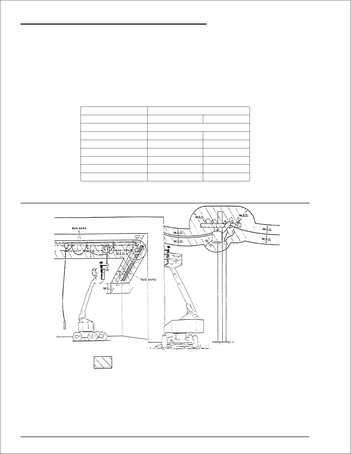
Minimum Safe Approach Distance
The Snorkelift is an all metal boom, NOT ELECTRICALLY INSULATED, aerial work platform. DO NOT
operate it near ELECTRICAL conductors. Regard all conductors as being energized. Use the table and
illustration below to determine safe clearance from electrical conductors. Table 1 and Figure 3 are
reprinted courtesy of Scaffold Industry Association, ANSI/SIA A92.5, page 23.
Table 1 - (M.S.A.D.)
❑
Minimum Safe Approach Distance
to energized (exposed or insulated power lines)
Voltage range Minimum safe approach distance
(phase to phase)
0 to 300V
over 300v to 50kv
over 50kv to 200kv
over 200kv to 350kv
over 350kv to 500kv
over 500kv to 750kv
over 750kv to 1000kv
(Feet) (Meters)
Avoid contact
10
15
20
25
35
45
3.05
4.60
6.10
7.62
10.67
13.72
Figure 3 - (M.S.A.D.)
❑
Denotes prohibited zone
Danger: - Do not allow machine personnel or conductive
materials inside prohibited zone.
- Maintain M.S.A.D. from all energized lines and parts
as well as those shown.
- Assume all electrical parts and wires are energized
unless known otherwise.
Caution:
page - ii AB46J – 0163187
- Diagrams shown are only for purposes of illustrating
M.S.A.D. work positions, not all work positions.
Page 5
Introduction
The most important chapter in this manual is
"Safety" chapter 1. Take time, now, to study it
closely. The information in chapter 1, might save
your life or prevent serious injury.
■
Signs
The following three conventions are used
throughout this manual.
1. Danger sign
DANGER
means: Attention! Become alert! Your safety is
involved.
2. Caution sign
CAUTION
means one of two things: (1) an action, about
to be performed, is potentially hazardous and
might result in minor personal injury if not
done correctly, or (2) an action, about to be
performed, can harm the Snorkelift if not done
correctly.
3. Note sign
■
Operation rules
The following rules will help ensure the safety of
personnel and help prevent needless downtime
because of damaged equipment.
1. Only TRAINED and AUTHORIZED operators
shall be permitted to operate the equipment.
2. All manufacturer’s operating instructions and
safety rules and all employers’ safety rules
and all OSHA and other government safety
rules must be strictly adhered to.
3. Repairs and adjustments shall be made only
by QUALIFIED TRAINED maintenance
personnel.
4. No modification shall be made to the
equipment without prior written consent of
the Snorkel Engineering Department.
5. You must make a pre-start inspection of the
Snorkelift at the beginning of each shift. A
malfunctioning machine must not be used.
6. You must make an inspection of the work
place to locate possible hazards before
operating the Snorkelift.
DANGER
means: The information following is to assist
you in either the proper steps to take for an
action or as addition information concerning
your present situation, but does not indicate a
dangerous condition to either you or the
Snorkelift unit.
■
Qualified operators
The Snorkelift aerial platform has built-in safety
features and has been factory tested for
compliance with Snorkel specifications and
industry standards. However, any
personnel-lifting device can be potentially
dangerous in the hands of untrained or careless
operators.
Training is vitally important and MUST be done
under the direction of a QUALIFIED person. You
must display proficiency in knowledge and actual
operation of the Snorkelift.
Before operation of the Snorkelift you must read
and understand the operating instructions in this
manual as well as the decals, warnings, and
instructions on the machine itself.
Before operating the Snorkelift you must be
AUTHORIZED by the person in charge to do so.
DO NOT operate this equipment unless you
are TRAINED and AUTHORIZED and have
read and thoroughly understand all of the
information given in this Operator’s Manual
and on all DANGER and CAUTION signs on
the machine. Misuse of this machine can
result in DEATH or SERIOUS INJURY.
■
Maintenance
Every person who maintains, inspects, tests, or
repairs these machines, and every person
supervising any of these functions, MUST be
properly trained.
This Operator’s Manual provides a daily
inspection procedure that will help you keep your
Snorkelift in good operating condition. DO NOT
perform other maintenance unless you are a
TRAINED mechanic, QUALIFIED to work on the
Snorkelift. Call QUALIFIED maintenance
personnel if you find problems or malfunctions.
DO NOT modify this machine without written
approval from the Engineering Department of
Snorkel.
Information contained in this manual concerns
only current Snorkelift's, and the right is reserved
to make changes at any time without obligation.
AB46J – 0163187 page - iii
Page 6

Introduction
■
Responsibilities of parties
It is imperative that all owners and users of the
Snorkelift read, understand, and conform to all
applicable regulations. Ultimate compliance to
OSHA regulations is the responsibility of the
employer using the equipment.
DANGER
ANSI Standard A92.5-1992 clearly identifies
requirements of all parties who might be
involved with Boom-Supported Elevating Work
Platforms.
A reprint of the “Manual of Responsibilities for
Dealers, Owners, Users, Operators, Lessors
and Lessees of ANSI/SIA A92.5-1992 Boom
Supported Elevating Work Platforms” is
available from Snorkel dealers or from the
factory upon request.
Copies are also available from:
Scaffold Industry Association
20335 Ventura Blvd. Suite 310
Woodland Hills, CA 91364-2471 USA
■
OSHA, ANSI and CSA Standards
The Snorkelift is a boom-supported elevating
work-platform built to conform to the following
standards:
OSHA Paragraph 1910.67 Title 29, C.F.R.
Vehicle-Mounted Elevating and Rotating
Work Platforms - Labor.
CALIFORNIA
Proposition 65 Warning
Battery posts, terminals and related accessories contain
lead and lead components, chemicals known to the
State of California to cause cancer and birth defects or
other reproductive harm. Wash hands after handling.
■
Options
The use of optional equipment is discussed in the
“Options” chapter 11.
The options you will find discussed there are:
1. Air line to platform.
2. BumpGard system.
3. Flashing lights.
4. Motion warning alarm.
5. Platform swinging gate.
■
Additional information
For additional information contact your local
dealer or Snorkel at:
Snorkel International, Inc.
P.O. Box 1160
St. Joseph, MO 64502-1160 USA
816-364-0317
http://www.snorkelusa.com
OSHA Paragraph 1926.556 Title 29, C.F.R.
Aerial Lifts - Construction.
ANSI Standard A92.5-1992
Boom-Supported Elevating Work Platforms.
CSA Standard CAN 3-B354.4-M82
Boom-type Elevating Work Platforms.
■
California Proposition 65 warning
The state of California requires that all equipment
used within its boundaries shall have the
following warning noted in the Operator’s Manual.
CALIFORNIA
Proposition 65 Warning
Diesel and gasoline engine exhaust and some of its
constituents are known to the State of California to
cause cancer, birth defects, and other reproductive
harm.
page - iv AB46J – 0163187
Page 7

Table of Contents
Electrical Hazard
Electrical Hazard Warning . . . . . . . . . . . . . . . . . . i
Minimum Safe Approach Distance . . . . . . . . . . . ii
Table 1 - (M.S.A.D.). . . . . . . . . . . . . . . . . . . . . . ii
Figure 3 - (M.S.A.D.) . . . . . . . . . . . . . . . . . . . . . ii
Introduction
Signs. . . . . . . . . . . . . . . . . . . . . . . . . . . . . . . . . . iii
Qualified operators . . . . . . . . . . . . . . . . . . . . . . . iii
Operation rules. . . . . . . . . . . . . . . . . . . . . . . . . . iii
Maintenance. . . . . . . . . . . . . . . . . . . . . . . . . . . . iii
Responsibilities of parties . . . . . . . . . . . . . . . . . iv
OSHA, ANSI and CSA Standards . . . . . . . . . . . iv
California Proposition 65 warning . . . . . . . . . . . iv
Options. . . . . . . . . . . . . . . . . . . . . . . . . . . . . . . . iv
Additional information. . . . . . . . . . . . . . . . . . . . . iv
1. Safety
Safe Operation. . . . . . . . . . . . . . . . . . . . . . . . . 1-1
Pre-start Inspection . . . . . . . . . . . . . . . . . . . . 1-1
Work Place Inspection and Practices . . . . . . 1-1
Electrocution . . . . . . . . . . . . . . . . . . . . . . . . . 1-2
Tipover and Falling Hazards . . . . . . . . . . . . . 1-2
Crushing . . . . . . . . . . . . . . . . . . . . . . . . . . . . 1-2
General Safety Precautions. . . . . . . . . . . . . . . 1-2
Personnel Precautions . . . . . . . . . . . . . . . . . 1-2
Operator General Precautions . . . . . . . . . . . 1-2
Mounting and Dismounting Precautions . . . . 1-2
Starting and Stopping Precautions . . . . . . . . 1-3
Operating Precautions . . . . . . . . . . . . . . . . . 1-3
Operator Maintenance Precautions . . . . . . . 1-3
Safety Decals and Placards . . . . . . . . . . . . . . 1-3
2. Safety Devices
Safety device information . . . . . . . . . . . . . . . . 2-1
Emergency Power Battery. . . . . . . . . . . . . . . 2-1
Emergency stop switches . . . . . . . . . . . . . . . 2-1
Flashing Lights . . . . . . . . . . . . . . . . . . . . . . . 2-2
Platform Foot Switch . . . . . . . . . . . . . . . . . . . 2-2
GFCI (Ground Fault Circuit Interrupt) . . . . . . 2-2
Platform Gravity Gate . . . . . . . . . . . . . . . . . . 2-2
Ground Operation Switch. . . . . . . . . . . . . . . 2-3
Platform Guardrails . . . . . . . . . . . . . . . . . . . . 2-3
Operator Horn . . . . . . . . . . . . . . . . . . . . . . . . 2-3
Lanyard Anchor Points . . . . . . . . . . . . . . . . . 2-3
Level Sensor . . . . . . . . . . . . . . . . . . . . . . . . . 2-4
Motion Warning Alarm. . . . . . . . . . . . . . . . . . 2-4
Platform Swinging Gate . . . . . . . . . . . . . . . . 2-4
Tilt Alarm . . . . . . . . . . . . . . . . . . . . . . . . . . . . 2-4
3. Specifications
General Specifications. . . . . . . . . . . . . . . . . . . 3-1
Model drawing and overall dimensions . . . . . . 3-2
Working envelope . . . . . . . . . . . . . . . . . . . . . . 3-3
Nomenclature and serial numbers . . . . . . . . . 3-4
Right hand side of chassis and turntable . . . 3-4
Left hand side of chassis and turntable . . . . 3-4
4. Gauges, Circuit Breakers and Displays
Gauges . . . . . . . . . . . . . . . . . . . . . . . . . . . . . . 4-1
Ammeter . . . . . . . . . . . . . . . . . . . . . . . . . . . . 4-1
Hour Meter . . . . . . . . . . . . . . . . . . . . . . . . . . 4-1
Hydraulic Oil Filter. . . . . . . . . . . . . . . . . . . . . 4-1
Hydraulic Oil Level . . . . . . . . . . . . . . . . . . . . 4-2
Hydraulic Oil Temperature. . . . . . . . . . . . . . . 4-2
Circuit Breakers . . . . . . . . . . . . . . . . . . . . . . . . 4-2
GFCI Circuit Breaker. . . . . . . . . . . . . . . . . . . 4-3
Battery Charger Circuit Breaker . . . . . . . . . . 4-3
Electronic Display . . . . . . . . . . . . . . . . . . . . . . 4-3
5. Batteries and Battery Charging
Batteries . . . . . . . . . . . . . . . . . . . . . . . . . . . . . 5-1
Battery charging . . . . . . . . . . . . . . . . . . . . . . . 5-2
6. Controls
Controls Description . . . . . . . . . . . . . . . . . . . . 6-1
Controls and Control Decals Locations. . . . . 6-1
Electronic Display Window . . . . . . . . . . . . . . 6-1
Ground Control Box. . . . . . . . . . . . . . . . . . . . . 6-2
Ground Control Box Controls . . . . . . . . . . . . 6-3
Platform Control Box . . . . . . . . . . . . . . . . . . . . 6-4
Platform Control Box Controls. . . . . . . . . . . . 6-5
Electronic Display . . . . . . . . . . . . . . . . . . . . . . 6-5
Information messages. . . . . . . . . . . . . . . . . . 6-5
Wait messages . . . . . . . . . . . . . . . . . . . . . . . 6-5
Operator Action messages . . . . . . . . . . . . . . 6-5
Service Required messages . . . . . . . . . . . . . 6-5
Electronic Display Message Tables. . . . . . . . . 6-6
Information message table . . . . . . . . . . . . . . 6-6
Wait message table. . . . . . . . . . . . . . . . . . . . 6-6
Operator Action message table. . . . . . . . . . . 6-7
Service Required message table . . . . . . . . . 6-8
Platform Foot Switch . . . . . . . . . . . . . . . . . . . . 6-9
Chassis Controls . . . . . . . . . . . . . . . . . . . . . . . 6-9
Battery Switch . . . . . . . . . . . . . . . . . . . . . . . . 6-9
Battery Charger. . . . . . . . . . . . . . . . . . . . . . . 6-9
AB46J – 0163187 page - v
Page 8

Table of Contents
7. Daily Inspection and Maintenance
Daily Inspection and Maintenance Table. . . . . 7-1
Wiring harnesses. . . . . . . . . . . . . . . . . . . . . . . 7-2
Battery terminals . . . . . . . . . . . . . . . . . . . . . . . 7-2
Battery fluid level . . . . . . . . . . . . . . . . . . . . . . . 7-3
Hydraulic oil . . . . . . . . . . . . . . . . . . . . . . . . . . . 7-3
Hydraulic oil leaks . . . . . . . . . . . . . . . . . . . . . . 7-3
Tires. . . . . . . . . . . . . . . . . . . . . . . . . . . . . . . . . 7-3
Bolts and fasteners. . . . . . . . . . . . . . . . . . . . . 7-4
Structural damage and welds . . . . . . . . . . . . . 7-5
Lanyard anchor points . . . . . . . . . . . . . . . . . . . 7-5
Platform guardrails . . . . . . . . . . . . . . . . . . . . . 7-5
Platform gravity gate . . . . . . . . . . . . . . . . . . . . 7-6
Platform swinging gate . . . . . . . . . . . . . . . . . . 7-6
Flashing lights . . . . . . . . . . . . . . . . . . . . . . . . . 7-6
Battery charger . . . . . . . . . . . . . . . . . . . . . . . . 7-6
Ground control box . . . . . . . . . . . . . . . . . . . . . 7-7
Level sensor . . . . . . . . . . . . . . . . . . . . . . . . . . 7-7
Platform control box. . . . . . . . . . . . . . . . . . . . . 7-7
Emergency power . . . . . . . . . . . . . . . . . . . . . . 7-8
GFCI (Ground Fault Circuit Interrupt) . . . . . . . 7-8
Slide pads . . . . . . . . . . . . . . . . . . . . . . . . . . . . 7-9
Hydraulic oil filter . . . . . . . . . . . . . . . . . . . . . . . 7-9
Placards and decals . . . . . . . . . . . . . . . . . . . 7-10
Optional placards and decals . . . . . . . . . . . 7-10
Standard placards and decals. . . . . . . . . . . 7-10
Inspection drawing number 1 . . . . . . . . . . . 7-11
Inspection drawing number 2 . . . . . . . . . . . 7-12
10. Stowing and Transporting
Stowing . . . . . . . . . . . . . . . . . . . . . . . . . . . . . 10-1
To Lock the AB46J . . . . . . . . . . . . . . . . . . . 10-1
Transporting. . . . . . . . . . . . . . . . . . . . . . . . . . 10-1
Trailering . . . . . . . . . . . . . . . . . . . . . . . . . . . 10-1
Securing to a Transport Vehicle. . . . . . . . . . . 10-2
Towing . . . . . . . . . . . . . . . . . . . . . . . . . . . . . . 10-4
Lifting . . . . . . . . . . . . . . . . . . . . . . . . . . . . . . . 10-4
11. Options
Air line to platform . . . . . . . . . . . . . . . . . . . . . 11-1
BumpGard System . . . . . . . . . . . . . . . . . . . . 11-1
Flashing Lights . . . . . . . . . . . . . . . . . . . . . . . 11-1
Motion Warning Alarm . . . . . . . . . . . . . . . . . . 11-2
Platform Swinging Gate. . . . . . . . . . . . . . . . . 11-2
12. Fire Fighting and Chemical Containment
Hazardous components. . . . . . . . . . . . . . . . . 12-1
Battery, Lead/Acid (UN 2794) . . . . . . . . . . . 12-1
Foam In Tires . . . . . . . . . . . . . . . . . . . . . . . 12-1
Hydraulic Oil (UN 1270) . . . . . . . . . . . . . . . 12-2
13. Operator's Troubleshooting
Troubleshooting . . . . . . . . . . . . . . . . . . . . . . . 13-1
Operator Troubleshooting Chart . . . . . . . . . 13-1
Accumulator Bleed Down Valve . . . . . . . . . 13-2
8. Operation
Operating Procedures . . . . . . . . . . . . . . . . . . . 8-1
Control Stations . . . . . . . . . . . . . . . . . . . . . . . . 8-1
Emergency Stopping . . . . . . . . . . . . . . . . . . . . 8-1
Starting From Ground Control Box . . . . . . . . . 8-2
Starting From Platform Control Box. . . . . . . . . 8-2
Moving The Platform . . . . . . . . . . . . . . . . . . . 8-3
From Ground Control Box . . . . . . . . . . . . . . . 8-4
From Platform Control Box . . . . . . . . . . . . . . 8-5
Driving . . . . . . . . . . . . . . . . . . . . . . . . . . . . . . . 8-6
Steering . . . . . . . . . . . . . . . . . . . . . . . . . . . . . . 8-6
Electrical (GFCI) Outlets at Platform . . . . . . . 8-6
Securing for Day . . . . . . . . . . . . . . . . . . . . . . . 8-6
9. Emergency Operation
Emergency Operation Procedures . . . . . . . . . 9-1
Operation From Platform Control Box . . . . . . 9-1
Operation From Ground Control Box . . . . . . 9-2
page - vi AB46J – 0163187
Page 9

■
Safe Operation
The following safety information is vitally
important for safe operation of the AB46J. Failure
to follow these instructions can result in personal
injury or DEATH.
Pre-start Inspection
❑
Prior to each shift, the AB46J shall be given a
visual inspection and function test. See the “Daily
Inspection and Maintenance” chapter 7, in this
manual for a list of items to inspect and test.
CAUTION
1. Safety
When moving the platform, check the clearance
around the AB46J to avoid contact with
structures or other hazards. Always look in the
direction of motion.
Keep ground personnel from under the platform
when the platform is raised.
Secure all accessories, containers, tools, and
other materials in the platform to prevent them
from accidentally falling or being kicked off the
platform.
Remove all loose objects stored in or on the
machine, particularly in the platform. Remove all
objects which do not belong in or on the machine.
DO NOT operate the AB46J unless you are
TRAINED and AUTHORIZED, understand the
operation characteristics of the AB46J, and
have inspected and tested all functions to be
sure they are in proper working order.
Work Place Inspection and Practices
❑
Before the AB46J is used, and during use, check
the area in which the AB46J is to be used for
possible hazards such as, but not limited to:
1. Drop-offs or holes.
2. Side slopes.
3. Bumps and floor obstructions.
4. Debris.
5. Overhead obstructions and high voltage
conductors.
6. Hazardous locations.
7. Inadequate surface and support to withstand
all load forces imposed by the aerial platform
in all operating configurations.
8. Wind and weather conditions.
9. Presence of unauthorized persons.
10. Other possible unsafe conditions.
Before the AB46J is used, determine the hazard
classification of any particular atmosphere or
location according to ANSI/NFPA 505-1987.
Any AB46J operated in a hazardous location
must be approved and of the type required by
ANSI/NFPA 505-1987.
DO NOT engage in any form of “horseplay” or
“stunt driving” while operating the AB46J.
DO NOT permit riders on the machine anyplace
other than on the platform.
When other moving equipment is in the area,
take special precautions to comply to local
regulations regarding warnings.
Never steady the platform by positioning it
against another platform.
DO NOT operate an AB46J that is not functioning
properly, or has been damaged, until the machine
has been repaired by a qualified maintenance
person.
DO NOT operate an AB46J that does not have all
its Decals and Placards attached and legible.
Drive the machine with care and at speeds
compatible with conditions. Use extra caution
when driving over rough ground, on slopes, and
when turning.
Know and understand the job site traffic flow
patterns and obey the flagmen, road signs, and
signals.
Watch for bystanders and never allow anyone to
be under, or to reach through, the machine and
its equipment while operating.
Use the recommended transport device when
loading the machine.
A recommended safety practice is to have
personnel that are trained in the operation of the
emergency controls working in the immediate
area of the AB46J to assist the platform operator
in the event of an emergency.
AB46J – 0163187 page 1 - 1
Page 10

1. Safety
Electrocution
❑
The AB46J is an all metal boom, NONINSULATED, aerial work platform. DO NOT
operate it near ELECTRICAL conductors. Regard
all conductors as being energized.
DO NOT operate outside during a thunderstorm.
Tipover and Falling Hazards
❑
DO NOT operate an AB46J from a position on
trucks, trailers, railway cars, floating vessels,
scaffolds, or similar equipment unless the
application is approved in writing by Snorkel.
If the platform or elevating assembly becomes
caught, snagged, or otherwise prevented from
normal motion by an adjacent structure or other
obstacles such that control reversal does not free
the platform, remove all personnel from the
platform before attempts are made to free the
platform using ground controls.
The guardrail system is your primary fall
protection. Never operate without all parts of the
guardrail system in place and the gate closed.
Under normal working conditions it is best not to
transfer from the platform to another structure or
vice versa, unless that is the safest way to do the
job. Each situation must be judged separately
taking the work environment into account. The
following guidelines apply:
1. Where possible, place the work platform over
a roof or walking structure to do the transfer.
2. Transfer your anchorage from one structure
to another before you step across.
3. Remember, you might be departing the work
platform to a structure where fall arrest is
required.
4.
DO NOT climb the rails. Use the entrance.
Maintain a firm footing on the platform floor.
Climbing on the guardrails is prohibited.
DO NOT use ladders, planks, or other devices to
extend or increase your work position from the
platform.
All platform occupants MUST use fall restraint.
Attach fall restraints to the platform anchorage
points.
DO NOT exceed the unrestricted platform
capacity as indicated on the capacity placard on
the platform.
DO NOT raise the boom if the AB46J is on soft
ground. Operate the boom only on a firm surface
capable of withstanding all load forces imposed
by the aerial platform in all operating conditions.
Raise the platform only when the AB46J is on
level ground.
DO NOT carry loads from any point outside of the
platform.
Care shall be taken to prevent rope, electric
cords, and hoses, etc., from becoming entangled
in the aerial platform.
DO NOT jerk the controls. Move the controls
slowly and deliberately to avoid jerky and erratic
operation. Always stop the controls in the neutral,
off, position before going in the opposite direction.
DO NOT use the boom for any purpose other than
to position personnel, their tools, and materials.
DO NOT use the AB46J as a crane, hoist, or jack.
DO NOT operate the AB46J in winds, or wind
gusts, of 28 mph (45 km/h) or more.
DO NOT add anything to the AB46J that will
increase the wind loading ( banners, flags, etc.).
Crushing
❑
Always look in the direction of travel. Avoid
overhead obstructions.
Never cover the floor grating or otherwise
obstruct your view below.
Make sure the area below the platform is free of
personnel before lowering.
■
General Safety Precautions
❑
Personnel Precautions
If you encounter any suspected malfunction of
the aerial platform, or any hazard or potentially
unsafe condition relating to capacity, intended
use, or safe operation, cease operation and seek
assistance from management.
❑
Operator General Precautions
Make sure that all protective guards, cowlings,
and doors are in place and secure.
Be sure the guardrail system, including the gate,
is in place and secure.
❑
Mounting and Dismounting Precautions
Use three points of support when getting on or off
the platform (e.g., two hands and one foot).
Keep the platform clean.
DO NOT jump off the machine.
DO NOT dismount while the machine is in motion.
page 1 - 2 AB46J – 0163187
Page 11

Starting and Stopping Precautions
❑
DO NOT start until all personnel are clearly away
from the machine.
Before leaving the operator’s station, place the
machine in the stowed position.
When leaving the machine parked or unattended,
remove the starter key from the Master Switch,
set the Battery switch to OFF, then lock the
Battery switch.
Operating Precautions
❑
DO NOT modify the AB46J in any way.
When parts or components are replaced, they
shall be identical or equivalent to original Snorkel
parts or components.
DO NOT override any of the safety features of the
AB46J.
Limit travel speeds according to conditions. Take
into account: grade, surface, congestion, visibility,
side slope, location of personnel, and other
hazards.
Operator Maintenance Precautions
❑
Charge batteries in a well-ventilated area free of
flame, sparks, or other hazards that might cause
fire or explosion.
1. Safety
■
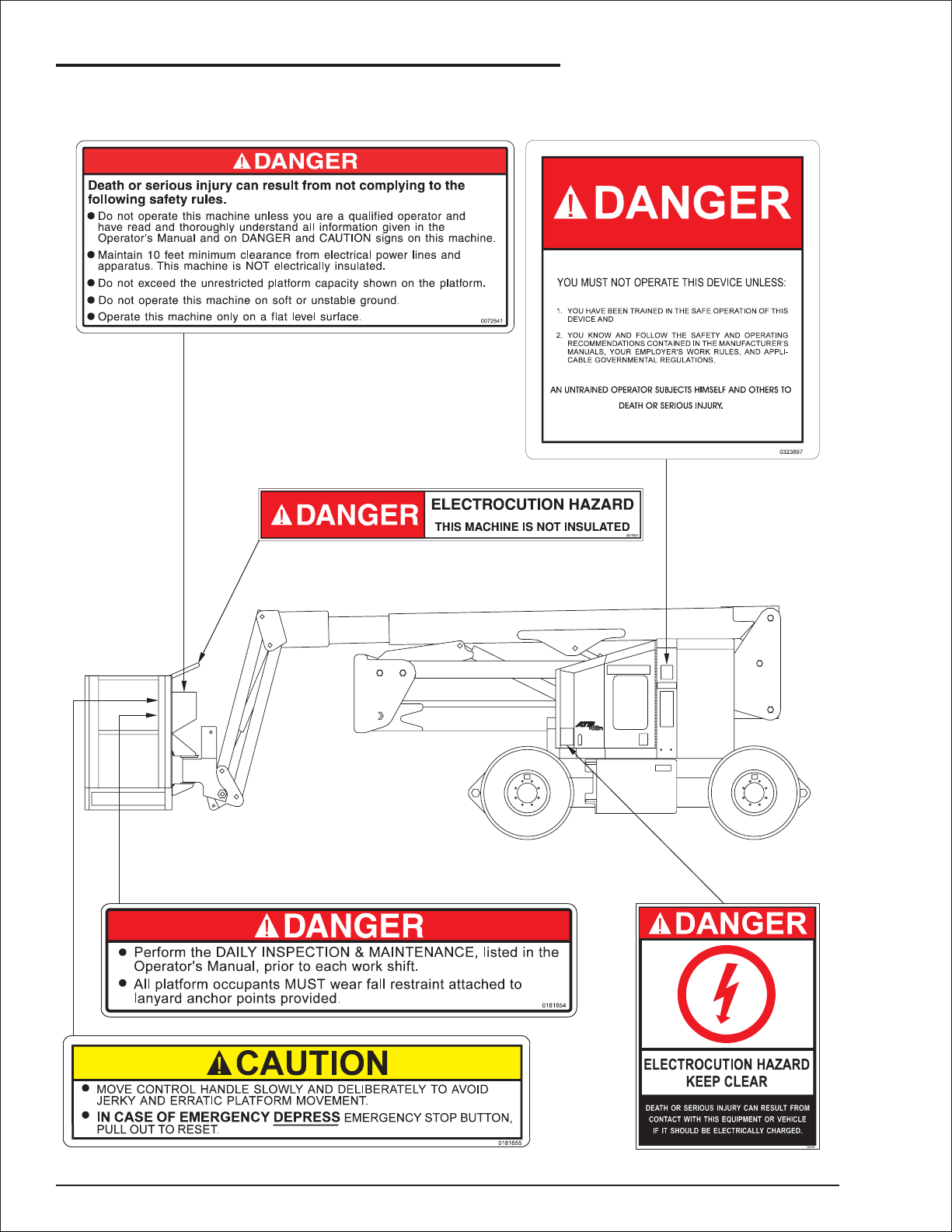
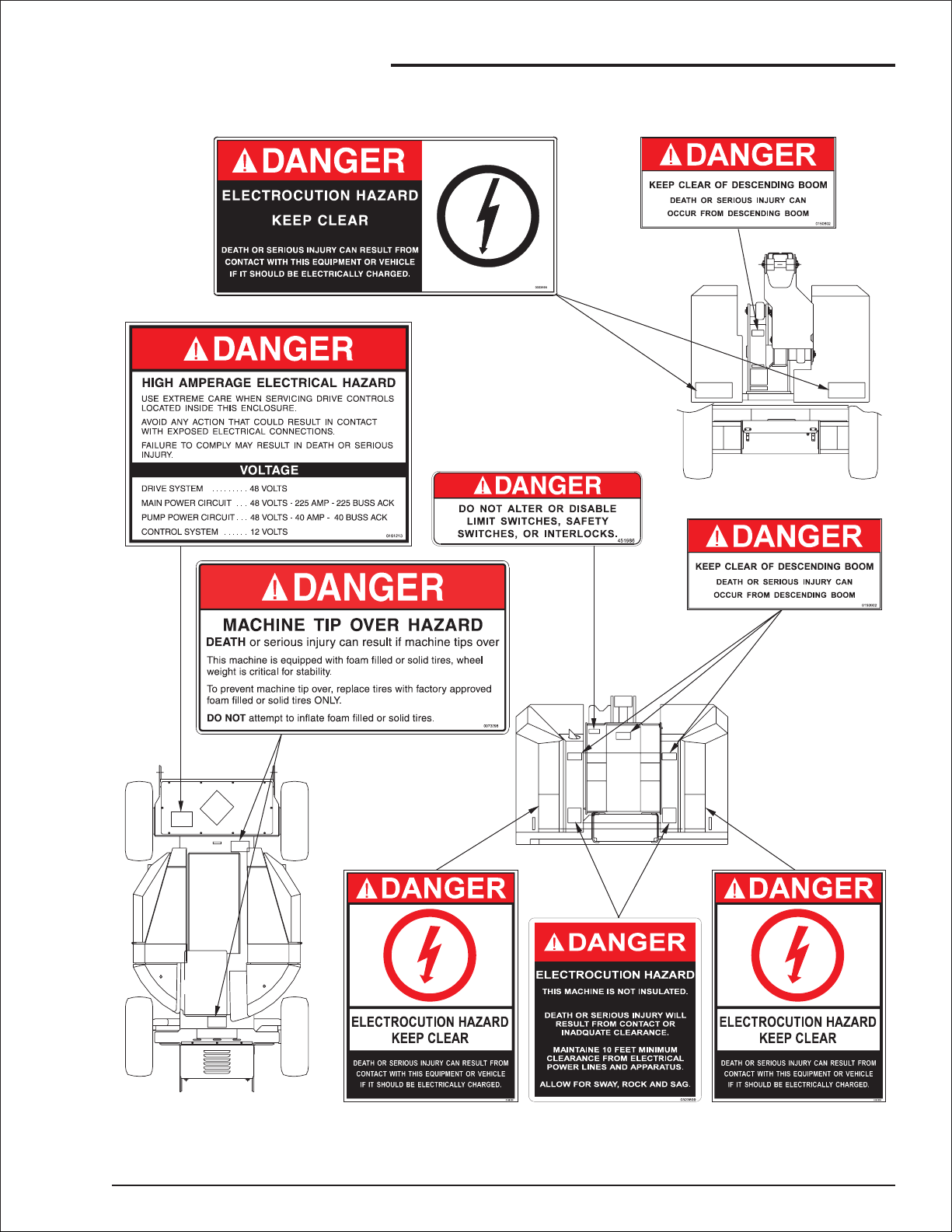
Safety Decals and Placards
There are several safety decals and placards on
the AB46J. Their locations and descriptions are
shown in this section. Take time to study them.
CAUTION
Be sure that all the safety decals and placards
on the AB46J are legible. Clean or replace
them if you cannot read the words or see the
pictures. Clean with soap & water and a soft
cloth. DO NOT use solvents.
You must replace a decal or placard if it is
damaged, missing, or cannot be read. If it is
on a part that is replaced, make sure a new
decal or placard is installed on the replaced
part. See your Snorkel dealer for new decals
and placards.
Refer to Placards and Decals Inspection Chart
and drawing in the “Daily Inspection and
Maintenance” chapter 7, for part numbers,
location, and required quantities of all placards
and decals.
Lead-acid batteries contain sulfuric acid. Sulfuric
acid will damage your eyes or skin on contact.
When you work around lead-acid batteries, wear
a face shield to avoid getting acid in your eyes.
Wear rubber gloves and protective clothing to
keep acid off your skin. If acid contacts your eyes,
flush immediately with clear water and get
medical attention. If acid contacts your skin, wash
off immediately with clear water.
CAUTION
DO NOT use your hand to search for hydraulic
oil leaks. High pressure hydraulic oil can easily
cut and penetrate your skin-averyserious
injury that requires immediate attention by a
medical specialist trained in that type of injury.
Use a piece of cardboard or wood to search
for hydraulic oil leaks.
DO NOT attempt repairs unless you are
trained. Refer to manuals and experienced
repair personnel for help.
AB46J – 0163187 page 1 - 3
Page 12
1. Safety
page 1 - 4 AB46J – 0163187
Page 13
1. Safety
AB46J – 0163187 page 1 - 5
Page 14

Page 15
2. Safety Devices
■
Safety device information
For emergency operation controls and
procedures, see the “Emergency Operation”
chapter 9, in this manual.
The devices listed in this chapter are safety
devices. They are on an AB46J to increase safety
in the work place for both the operator and other
people near an AB46J. DO NOT by-pass, disable,
modify, or ignore any of these devices. Check
them carefully at the start of each work shift to
see that they are in working order (see “Daily
Inspection and Maintenance” chapter 7).
If any is found to be defective, immediately
remove the AB46J from service until a qualified
service technician can make repairs.
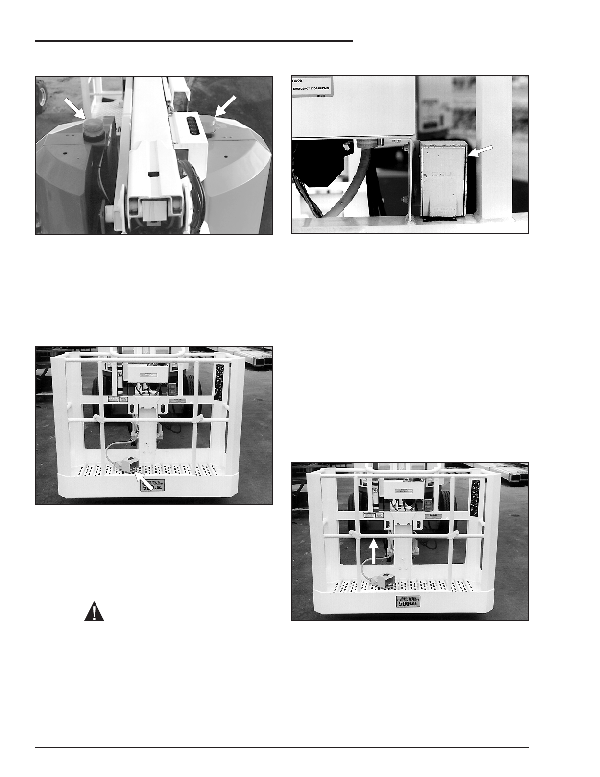
Emergency Power Battery
❑
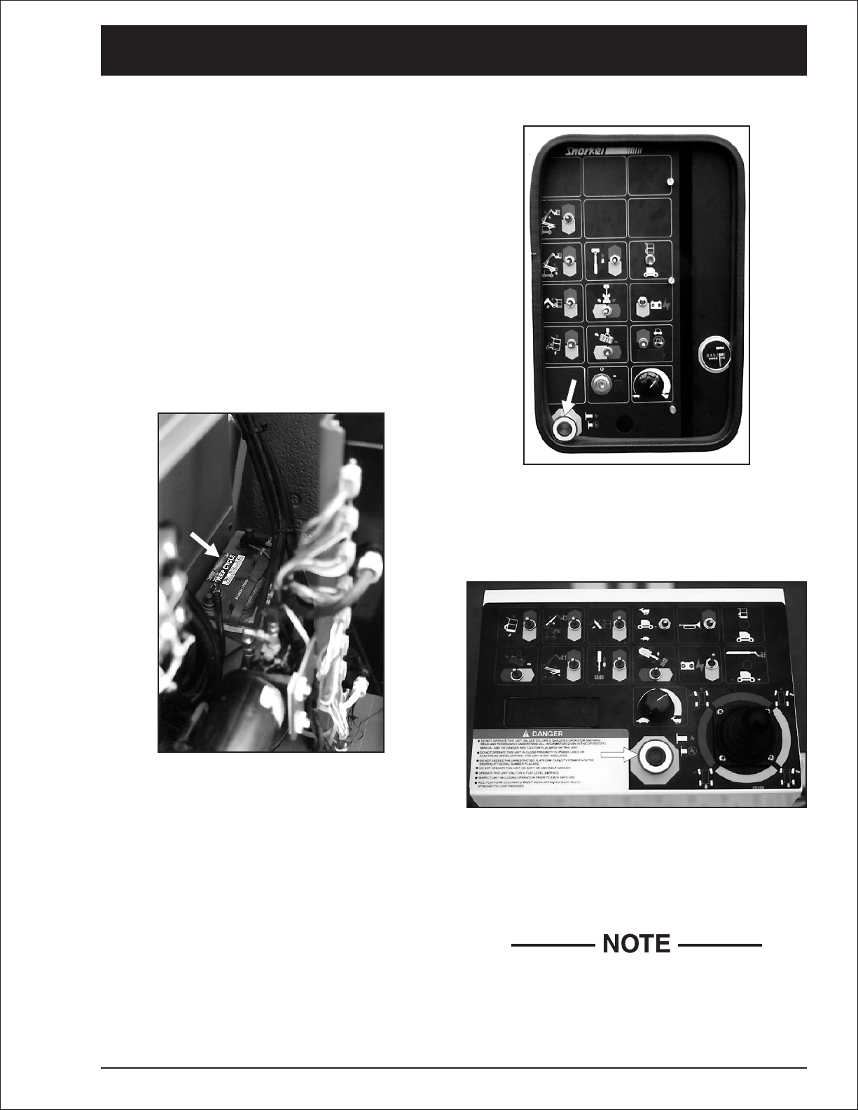
Emergency stop switches
❑
At the ground control box: Press the large red
Emergency Stop button in, at any time, under
any conditions, and the entire machine stops, the
drive motors and pump turn off, the brakes
automatically set, and nothing moves. This switch
must be pulled out (on) for anything to work.
The emergency power battery powers the
emergency operating circuits. If the platform is
aloft when regular power fails, emergency battery
power is the only way to lower the platform, there
is no manual bleed down procedure.
Thus, maintenance of the emergency power
battery is very important. The emergency power
battery should always be kept at full charge and
the battery terminals kept free of corrosion.
AB46J – 0163187 page 2 - 1
At the platform control box: Press the large red
Emergency Stop button down (off) and the
entire machine stops, the drive motors and pump
turn off, the brakes automatically set, and nothing
moves. This switch must be pulled to its up (on)
position to control the AB46J from the platform.
The ground control box will override the
platform control box. If the platform control box
Emergency Stop button is down (off) the
ground control box can still be used to start
and operate the AB46J.
Page 16
2. Safety Devices
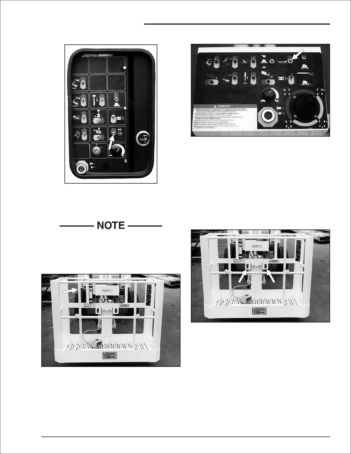
Flashing Lights
❑
GFCI (Ground Fault Circuit Interrupt)
❑
The optional flashing lights alert people that the
AB46J is present. The lights flash at about one
flash per second any time the Battery switch,
Master Key Switch, and the Emergency Stop
switch (at the ground) are all ON. There is no
ON/OFF switch for the flashing lights.
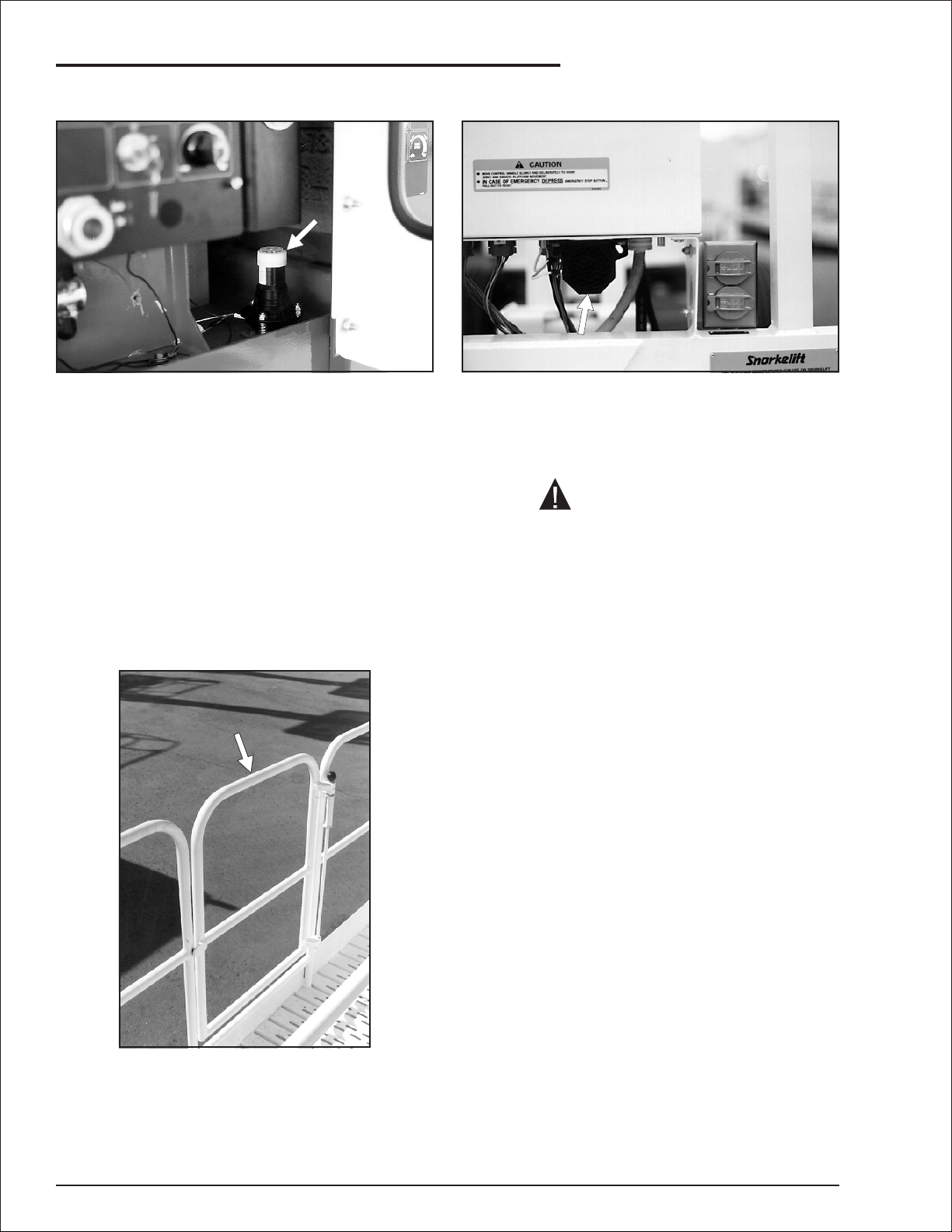
Platform Foot Switch
❑
The platform foot switch prevents the platform
from moving if something accidentally pushes
one of the platform moving controls on the
platform control box. (Stepping on the foot switch
is an action that must be performed, at the same
time as another action, to make the platform
move.)
The (GFCI) ground fault circuit interrupt is located
near the platform control box. To use the outlets,
connect the power input connector, on the top
rear of the chassis, to a source of 125 volt AC,
15 A electrical power.
The GFCI protects against electricity flowing to
ground. When electricity flows to ground the
GFCI shuts off power to the electrical outlets.
To reset the outlets:
1. Unplug the equipment being used.
2. Press the RESET button on the GFCI.
This should restore power to the outlets. If it does
not, unplug the source of power and refer the
problem to a trained service technician.
❑
Platform Gravity Gate
DANGER
Serious Injury can result from sudden stops.
To avoid sudden stops, Do Not remove your
foot from the foot switch while the AB46J is in
motion.
page 2 - 2 AB46J – 0163187
The platform gravity gate is the place in the
platform guardrail system where you should enter
and leave the platform. Raise the gate and step
under it onto the platform. Once you have entered
the platform and attached your fall restraint
lanyard to an anchor point, check to see that the
gravity gate has fallen back into place.
Page 17
Ground Operation Switch
❑
The Ground Operation switch prevents the
platform from moving if something accidentally
pushes one of the platform moving switches at
the ground control box.
2. Safety Devices
Operator Horn
❑
The operator horn is used primarily to get the
attention of people on the ground when you are
working aloft.
For the horn to work the Battery switch must be
ON and the following switches, on the ground
control box, must be set as indicated:
Platform/Ground Selector . . . . . . PLATFORM
Emergency Stop . . . . . . . . . . . . . . . Pulled Out
Master Key Switch . . . . . . . . . . . . . . . . . . . ON
Pushing the Ground Operation switch is an
action that MUST be performed, at the same time
as another action, to make the platform move.
❑
Platform Guardrails
The platform guardrails help protect you from
falling off the platform. Be sure the guardrails are
properly installed and that the gate is in place.
Lanyard Anchor Points
❑
All personnel on the platform should attach their
fall restraint lanyards to one of the lanyard anchor
points.
AB46J – 0163187 page 2 - 3
Page 18
2. Safety Devices
Level Sensor
❑
The level sensor detects how far out of level the
turntable is. If the turntable gets over 5° out of
level the level sensor activates the tilt alarm
(described in this chapter).
Motion Warning Alarm
❑
The optional motion warning alarm emits a loud
beeping sound, at ground level, anytime the
Drive/Steer controller is in FORWARD or
REVERSE or anytime the booms move. This
alarm alerts people on the ground that the AB46J
is traveling along the ground.
❑
Platform Swinging Gate
Tilt Alarm
❑
The tilt alarm warns the AB46J operator that the
AB46J is over 5° out of level.
If the tilt continues to increase, the AB46J will
eventually tip over.
CAUTION
When you hear the loud two toned alarm,
(high-low-high-low...), immediately retract and
lower the platform. When the platform is
completely down, determine and correct the
cause of the tilt before raising the platform
again.
The optional platform swinging gate is designed
to automatically close after you enter or leave the
platform.
It helps prevent people from falling off the
platform.
page 2 - 4 AB46J – 0163187
Page 19

3. Specifications
The Snorkelift AB46J is a boom-supported
elevating work-platform built to conform to all
applicable OSHA, ANSI or CSA standards as
previously outlined.
■
General Specifications
Working height (nominal) . . . . . 52 ft-0in(15.8m)
Platform height (maximum) . . . . 46 ft-0in(14.0m)
Platform reach (maximum) . . . . . 24 ft-8in(7.5m)
Length, overall
(booms down and retracted). . . 19 ft-1in(5.8m)
Width, overall . . . . . . . . . . . . . . . . 5 ft-9in(1.8m)
Height (booms down) . . . . . . . . . . 6 ft-6in(2.0m)
Wheelbase . . . . . . . . . . . . . . . . . . 6 ft-7in(2.0m)
Ground clearance . . . . . . . . . . . . 6.25 in (15.9 cm)
Tailswing:
stowed. . . . . . . . . . . . . . . . . . .1ft-7in(0.48m)
working. . . . . . . . . . . . . . . . . . . . . . . . . 0 in (0 m)
Weight (approximate) . . . . . . 15,900 lbs (7,212 kg)
Electrical system . . . 48 V dc (neg. chassis ground)
Hydraulic oil system:
maximum pressure . . . . . 3,000 psi (20,700 kPa)
system capacity. . . . . . . . . 9 gal USA (34.0 liters)
maximum temperature (at tank) . . . 200°F(93°C)
Hydraulic oil - recommended type
above 10°F (-13°C) . . . . . . . . . . Mobil DTE-13M
below 10°F (-13°C). . . . . . . . . . . Mobil DTE-11M
Boom movement times
(complete range of movement):
Turntable Swing, 360° non-continuous
CW or CCW. . . . . . . . . . . . . 100 - 110 seconds
Platform Rotation, 180°
CW or CCW, . . . . . . . . . . . . . . 16 - 20 seconds
Main Boom Elevation, +74°/-1° to horizontal
UP. . . . . . . . . . . . . . . . . . . . . . 30 - 45 seconds
DOWN. . . . . . . . . . . . . . . . . . . 30 - 45 seconds
Riser Boom Elevation
UP. . . . . . . . . . . . . . . . . . . . . . 45 - 60 seconds
DOWN. . . . . . . . . . . . . . . . . . . 50 - 65 seconds
Maximum single wheel load. . . . 8200 lbs (3719 kg)
Ground pressure (maximum). . . . 115 psi (794 kPa)
Travel speeds (maximum)
(See “Controls” chapter 6, for explanation
of settings for different speeds.):
booms down and retracted
high speed . . . . . . . . . . . . . 3.0 mph (4.8 km/hr)
low speed. . . . . . . . . . . . . 0.75 mph (1.2 km/hr)
Gradeability. . . . . . . . . . . . . . . . . . . . . . . . . . . 25%
Platform size:
standard aluminum. . . . . 30 x 60 in (76 x 152 cm)
Unrestricted rated work load
(total weight of personnel, tools and
equipment that platform is designed
to carry above its floor):
rated work load . . . . . . . . . . . . 500 lbs (227 kg)
occupants . . . . . . . . . . . . . . . . . . . . . . 2 people
Environmental operating ranges:
ambient air temperature
Fahrenheit . . . . . . . . . . . . . . . . . . . 0°Fto+110°F
Centigrade. . . . . . . . . . . . . . . . . . -18°Cto+43°C
Main Boom Extension
OUT . . . . . . . . . . . . . . . . . . . . 20 - 40 seconds
IN . . . . . . . . . . . . . . . . . . . . . . 20 - 40 seconds
Jib Boom, +45°/-75° to horizontal
UP. . . . . . . . . . . . . . . . . . . . . . 25 - 40 seconds
DOWN. . . . . . . . . . . . . . . . . . . 25 - 40 seconds
wind speed
(maximum gust or steady) . . 28 mph (45 km/hr)
Turning radius, inside . . . . . . . . . 5 ft - 11 in (1.8 m)
Tires (foam filled) . . . . . . . . . . . 9.50 x 16.5 in, 8 ply
AB46J – 0163187 page 3 - 1
Page 20
3. Specifications
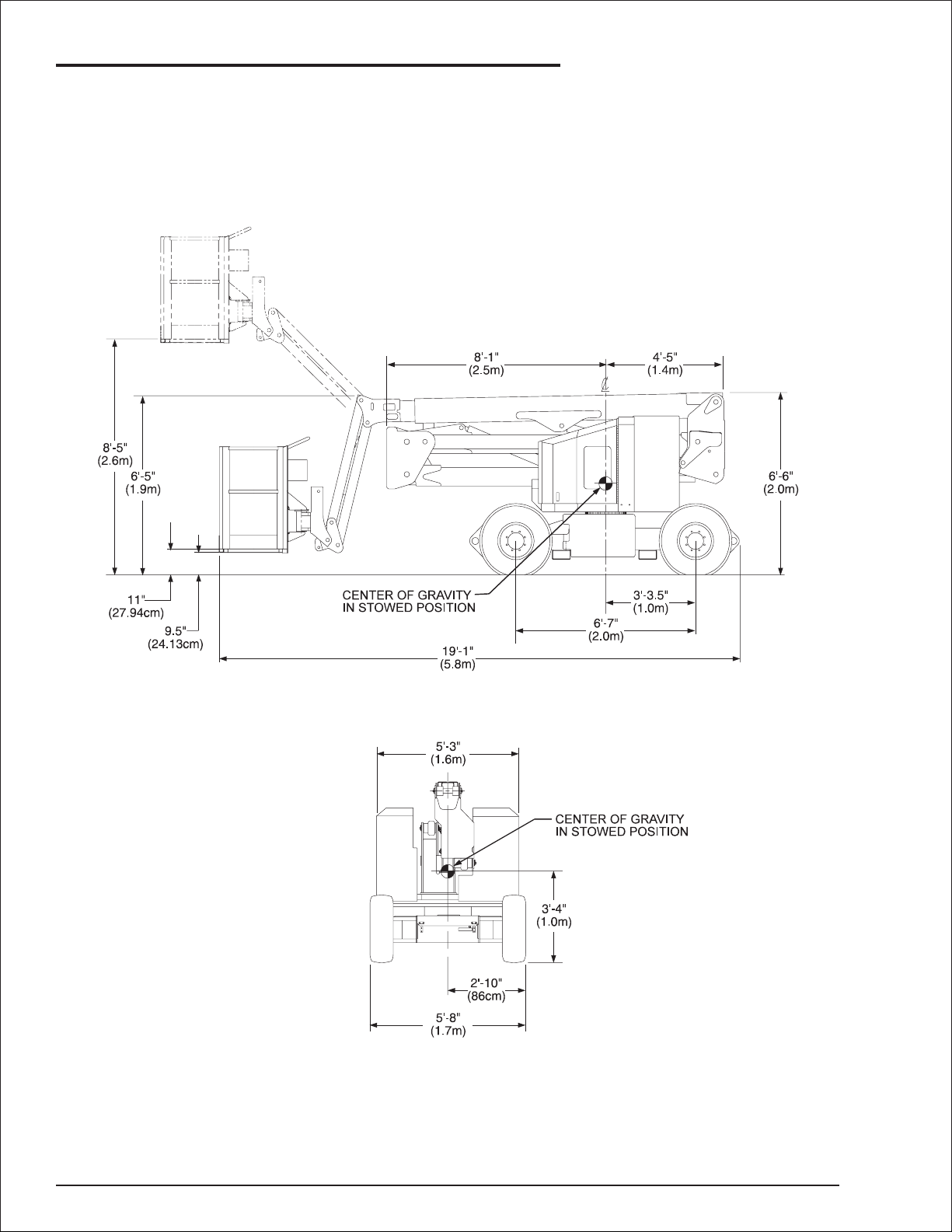
■
Model drawing and overall dimensions
page 3 - 2 AB46J – 0163187
Page 21
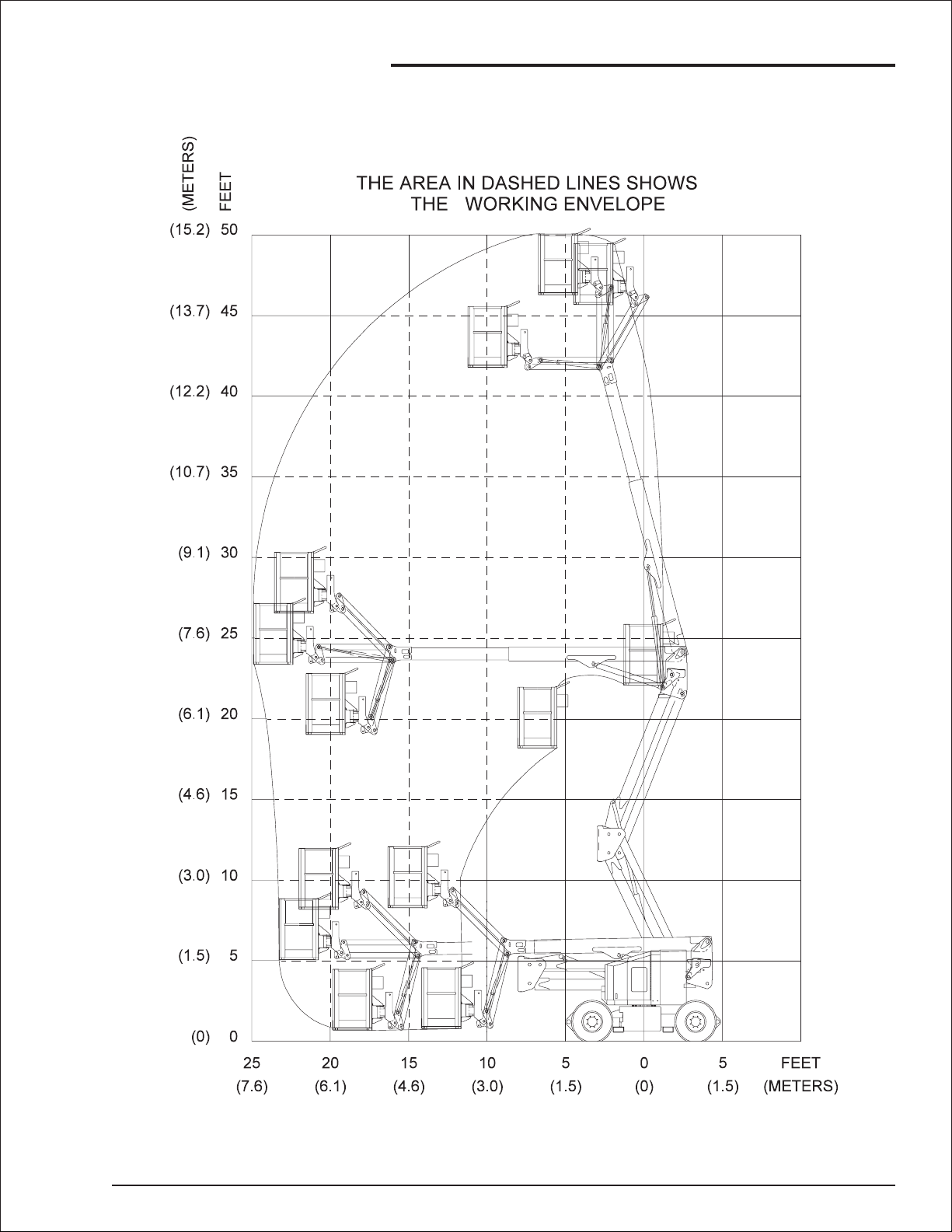
■
Working envelope
3. Specifications
AB46J – 0163187 page 3 - 3
Page 22
3. Specifications
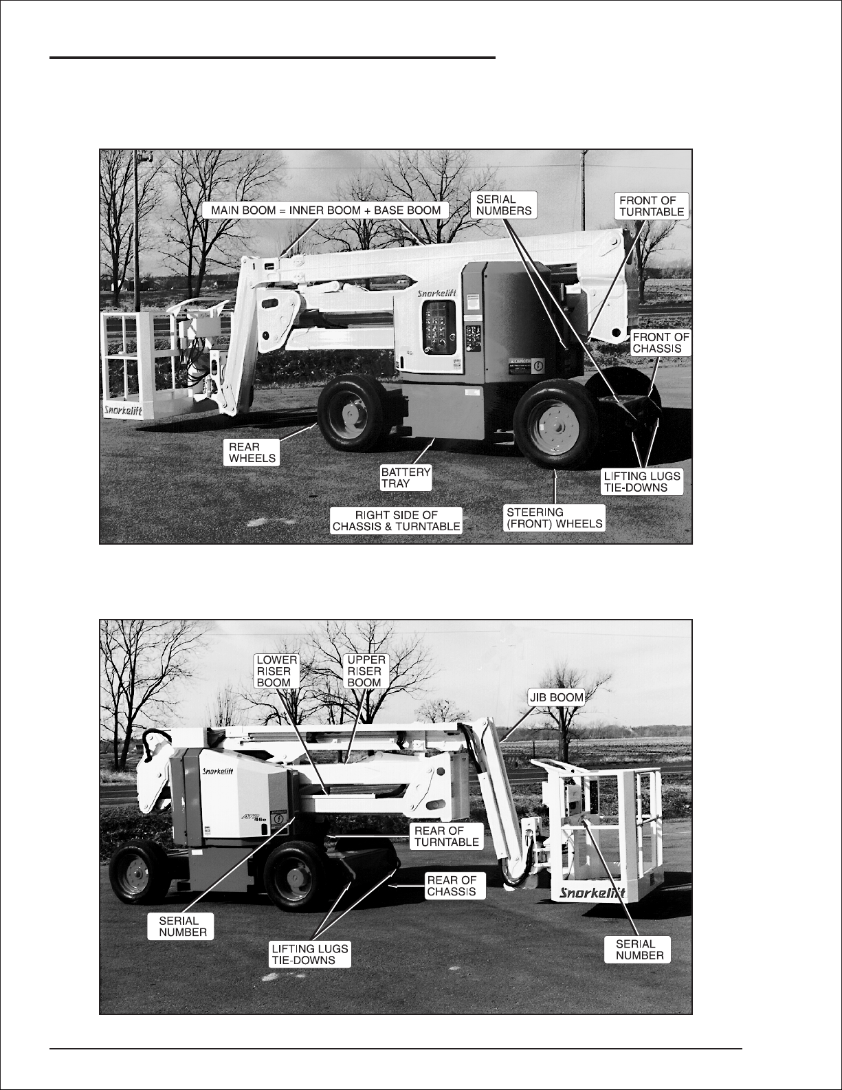
■
Nomenclature and serial numbers
Right hand side of chassis and turntable
❑
❑
Left hand side of chassis and turntable
page 3 - 4 AB46J – 0163187
Page 23
■
Gauges
4. Gauges, Circuit Breakers and Displays
Time will also accumulate when:
Ammeter
❑
The ammeter on the battery charger, shows the
DC charging current going to the batteries. See
the “Batteries and Battery Charging” chapter 5,
for a detailed discussion of the charging current.
Hour Meter
❑
Battery charger is disconnected,
Battery switch . . . . . . . . . . . . . . . . . . . . . . . ON
Platform/Ground Selector . . . . . . PLATFORM
Emergency Stop (ground). . . . . . . . . . . . . . ON
Master Key switch . . . . . . . . . . . . . . . . . . . . ON
Emergency Stop (platform). . . . . . . . . . . . . ON
Foot Switch . . . . . . . . . . . . . . . . . . Stepped On
The hour meter gauge cannot be reset. Use it to
tell when it is time to perform the periodic
maintenance listed in the Maintenance Manual.
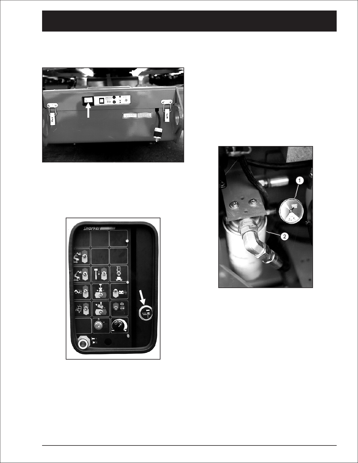
Hydraulic Oil Filter
❑
The hydraulic oil filter gauge (1) is located above
the hydraulic oil filter (2). The gauge measures
pressure into the filter. As the filter clogs, the
pressure goes up.
Check the condition of the filter, at the start of
each work shift, according to the procedure
described in the “Daily Inspection and
Maintenance” chapter 7, in this manual.
The Hour Meter gauge is basically an electric
clock. It accumulates time when any part of the
AB46J is in motion. Time will accumulate when
the following conditions occur simultaneously:
Battery charger is disconnected,
Battery switch . . . . . . . . . . . . . . . . . . . . . . . ON
Platform/Ground Selector . . . . . . . . GROUND
Emergency Stop (ground). . . . . . . . . . . . . . ON
Master Key Switch . . . . . . . . . . . . . . . . . . . ON
Ground Operation switch . . . . . . . . . . . . . . UP
AB46J – 0163187 page 4 - 1
Page 24

4. Gauges, Circuit Breakers and Displays
Hydraulic Oil Level
❑
The hydraulic oil level gauge (1) is on the side of
the hydraulic oil tank (2).
Hydraulic Oil Temperature
❑
The hydraulic oil temperature gauge measures
the temperature of the oil in the tank. The
temperature should not exceed 200°F (93°C).
If the temperature reaches its limits, reduce your
driving speed or stop the AB46J and let the
hydraulic oil cool.
■
Circuit Breakers
With the exceptions of the optional GFCI outlet at
the platform and the circuit breaker on the battery
charger, there are no other circuit breakers on an
AB46J that are accessible to an operator.
The gauge shows the actual level of oil inside the
tank.
Read it only when the booms are completely
down and completely retracted. Otherwise, the
boom hydraulic cylinders become large reservoirs
for hydraulic oil and the oil level in the tank will be
low. The oil level (3) should be between the high
mark (4) and low mark (5).
All of the other circuit breakers on an AB46J
automatically reset themselves about one minute
after they trip.
When a circuit breaker trips that will not reset, or
if it resets automatically but trips again,
immediately attempt to lower the platform to the
ground by using normal operating procedures.
If normal procedures do not work, use
emergency procedures see “Emergency
Operation” chapter 9, to lower the platform.
If the cause of the problem is not immediately
obvious, refer the problem to a qualified
service technician.
page 4 - 2 AB46J – 0163187
Page 25

4. Gauges, Circuit Breakers and Displays
GFCI Circuit Breaker
❑
If the 15 A circuit breaker on the GFCI outlet
trips, disconnect whatever is plugged into the
outlet, wait one minute, then press the circuit
breaker button back in. If the circuit breaker trips
a second time, refer the problem to a qualified
service technician.
Battery Charger Circuit Breaker
❑
If the circuit breaker in the battery charger trips,
wait one minute then press the circuit breaker
back in. If the circuit breaker trips a second time,
refer the problem to a qualified service
technician.
■
Electronic Display
The Electronic Display gives information about
the AB46J Drive system only.
The display does NOT give any information about
boom-moving functions or conditions.
If the ground fault circuit breaker on the GFCI
outlet trips, disconnect whatever is plugged into
the outlet, wait one minute, then press the
RESET button back in. If the circuit breaker trips
a second time, refer the problem to a qualified
service technician.
AB46J – 0163187 page 4 - 3
For a complete discussion of the Electronic
Display, see the “Electronic Display” section of
the “Operation” page 6-5.
Page 26

Page 27

■
Batteries
The following information about battery care and
maintenance was supplied by Interstate Batteries
and is reprinted here with their permission.
1. New batteries need to be cycled several
times before reaching full capacity (20-50
cycles, depending on type). Use should be
limited during this period.
2. Always fully recharge batteries immediately
after use. Batteries perform best when they
are fully charged. More capacity and longer
life will result from this practice.
3. The deeper the discharge, the fewer number
of cycles a lead/acid battery will deliver.
Deep discharges deteriorate the battery
quicker than lighter shallow cycles.
4. Battery cables should be intact, and
connectors kept tight at all times. Systematic
inspection is recommended.
5. Vent caps should be kept in place and tight
during vehicle operation and battery
charging.
6. Batteries should be kept clean - free of dirt
and corrosion - at all times. Always keep the
top of batteries clean. A film on top of the
battery can cause the current to migrate
between the posts, accelerating self
discharge.
7. Never let the electrolyte level of a lead-acid
battery fall below the plates. Lack of
maintaining the electrolyte in a lead-acid
battery causes damage to the exposed
portion of the plate which reduces capacity.
8. Always check electrolyte level before
charging. Do not add water to individual cells
unless plates are exposed. Batteries should
be watered after charging unless the plates
are exposed before charging. If exposed
before charging, the plates should be
covered by approximately 1/8” of water.
Check water level after charging. Water
should be kept 1/4” (6 mm) below the bottom
of the fill tube in the cell cover.
9. Water used to replenish batteries should be
distilled or treated to not exceed 200 T.D.S.
(total dissolved solids... parts per million).
Particular care should be taken to avoid
metallic solids (iron).
5. Batteries and Battery Charging
10. Always allow batteries to cool off after
charging. The cooling time is very important
because heat is generated during the
recharge and discharge cycles. Without the
cooling time the heat grows, accelerating grid
corrosion which is one of the major causes of
battery failure. Charging practice should
enable batteries to cool before use.
11. As batteries age, their maintenance
requirements change, Generally their specific
gravity is higher and gassing voltage goes
up. This means longer charging time and/or
higher finish rate (higher amperage at the
end of charge). Usually, older batteries need
to be watered more often and their capacity
decreases.
12. “Opportunity charging,” a short partial charge
during an extended duty cycle, is a
controversial subject. If you cannot charge the
batteries normally because of extreme
operating conditions (24 hour intermittent use,
as an example), “opportunity charging” is
better than excessive battery discharging.
However, the practice can cause batteries to
over heat, require more watering, and usually
will shorten battery life. “Opportunity charging”
is a trade off; something to avoid if possible.
One charging cycle per day is preferable.
13. Extreme temperatures can substantially affect
battery performance and charging. Cold
reduces battery capacity and retards
charging. Heat increases water usage and
can result in overcharging. Very high
temperature can cause “thermal run away”
which may lead to an explosion or fire. If
extreme temperature is an unavoidable part of
an application, consult a battery/charger
specialist about ways to deal with the
problem.
14. An overly discharged battery might need to be
cycled a few times before it can recover fully. If
a battery begins to heat before coming up to a
full charge, it might be necessary to discharge
the battery and recharge it a few times. The
charge and discharge cycle might help the
current acceptance of the battery and facilitate
its recovery to a usable condition.
15. Inactivity can be harmful to deep cycle
batteries. If they sit for several months, a
“boost” charge should be given - more
frequently in warm climate (about once a
month) than in cold (every 2-3 months).
16. Never store a battery in a discharged state.
The sulfate that forms during discharge can
make the battery impossible to recharge fully.
AB46J – 0163187 page 5 - 1
Page 28

5. Batteries and Battery Charging
■
Battery charging
CAUTION
DO NOT leave the battery charger on for more
than two days. The batteries might be severely
overcharged and/or damaged if the charger
fails to automatically turn off.
Keep all battery charger ventilation ports open
to prevent accumulation of explosive gasses
and heat.
1.
Turn the Master Key Switch on the ground
control box to OFF and the Battery switch
(1) ON.
4. Visually inspect the ammeter (4) for proper
charging rate.
●
Initial charge rate will vary from 18 to 22 A
depending on how deeply the batteries
have been discharged.
●
As the batteries become charged, the
ammeter will decrease to5Ato10A
depending on the condition of the
batteries. Allowing the charger to finish at
this low rate is essential to equalize the
charge of all battery cells. Leave the
battery charger plugged in until it
automatically turns itself off.
If the batteries are already fully charged when
you connect the charger, the ammeter (4) will
initially jump to 15 A to 20 A then quickly
decay to zero.
2. Set the Input Voltage switch (2) to 125 or 250
depending on whether you are going to plug
the battery charger into a 125 volt AC source
of power or a 250 volt AC source of power,
respectively.
If the ammeter (4) does not respond, check
the source of input power to be sure it is
turned on. Reset the 60 A circuit breaker (5) if
it has tripped. If the ammeter (4) still does not
respond, have a qualified service technician
check the input-power fuses (6).
5. After the battery charger has automatically
turned itself off, unplug the power cord.
3. Plug the battery charger (3) into a grounded
AC outlet (90 - 125/180 - 250 volt AC, 50/60
Hz), using a 3-conductor 12 gauge extension
cord that is in good electrical condition. Keep
the extension cord as short as possible.
The battery charger will start 3 to 5 seconds
after a complete electrical connection is
made.
page 5 - 2 AB46J – 0163187
Page 29

■
Controls Description
This chapter shows the controls at the ground
control box and the platform control box, and
explains what each control does.
This chapter DOES NOT explain how to use
the controls to produce useful work.
“Operation” chapter 8, covers the proper use
of controls.
See the “Emergency Operation” chapter 9, for
correct emergency operation procedures.
See the “Options” chapter 11, for correct
operation procedures of any optional equipment.
Controls and Control Decals Locations
❑
6. Controls
The main operating functions of an AB46J can be
controlled from the ground control box or from the
platform control box.
The names of the different controls on the ground
control box are shown on a decal next to the box.
The decal also shows the names of the different
settings to which each control can be set.
The names of the controls on the platform control
box are shown on a decal to the right of the box,
on the platform corner post. The decal also
shows the names of the different switch settings.
The Electronic Display automatically turns on
when platform control is selected, and displays
messages about the status of the drive system.
❑
Electronic Display Window
Platform Controls
Platform Controls Decal
(inside platform post)
Ground Controls Decal
Ground Controls
The Emergency Stop switch MUST be On
(pulled up) for the platform control box Electronic
Display to show messages.
After initial system diagnostics check, the system
will display a message that the system is "OK!
Depress platform foot switch to test battery.
DRIVE SYSTEM CHECK
***SYSTEM OK!***
Drive System is operable, only after the
"NEUTRAL VEL = 0.0 MPH" message is
displayed provided batteries have sufficient
charge for operation.
AB46J – 0163187 page 6 - 1
Page 30

6. Controls
■
Ground Control Box
Controls for operating the AB46J from the
ground, are located on the right side of the
turntable.
The number of each control below corresponds
to the control’s call out on the control box
illustration.
1.
Emergency Stop: Press the red button in, at
any time, under any conditions, and the
entire machine stops — the drive motors and
pump turn off, the brakes automatically set,
and nothing moves. This switch must be out
for anything on the machine to work.
2.
Platform/Ground Selector : Must be in the
GROUND position (down) for the ground
control box to work. The switch MUST be in
the PLATFORM position (up) for the platform
control box to work.
3.
Master Key Switch: This is the master on/off
switch. Turn the switch to ON to begin work
with the AB46J.
4.
Boom Speed: This control determines how
fast the booms move. Set it to SLOW (turtle)
until you are very familiar with the way the
machine works or if the platform is working in
dangerous or cramped surroundings.
5.
Ground Operation: You must manually hold
this switch up any time you use one of the
seven platform moving switches, (switches 6
through 12), to move the platform. Holding
the switch up turns the hydraulic pump on in
preparation to do work.
10.
Swing: CW (left) rotates the entire turntable
clockwise (as seen from above). CCW (right)
rotates the turntable counterclockwise.
11.
Platform Level: UP rotates the platform up
relative to the end of the jib boom. DOWN
rotates the platform down.
12.
Platform Rotate: CW (left) rotates the
platform clockwise (as seen from above)
relative to the end of the jib boom. CCW
(right) rotates the platform counterclockwise.
13.
Emergency Power: Continuously holding
this switch down activates a small, battery
powered hydraulic pump that supplies
emergency hydraulic power for the machine.
Boom movements will be slow and have long
lag times under EMERGENCY POWER.
DO NOT use this switch for normal operation.
Control switches 6 through 12 are the
platform moving switches. Each is a three
position, momentary contact, normally OFF
switch.
(See “Nomenclature and Serial Numbers” in
the “Specifications” chapter 3, for boom
identification.)
6.
Riser Lift: UP raises the upper and lower
riser booms. DOWN lowers them.
7.
Main Boom Lift: UP raises the base boom.
DOWN lowers the base boom.
8.
Extend/Retract: EXTEND extends the inner
boom out of the base boom. RETRACT
retracts the inner boom into the base boom.
9.
Jib: UP raises the jib boom. DOWN lowers
the jib boom.
page 6 - 2 AB46J – 0163187
Page 31

Ground Control Box Controls
❑
6. Controls
0161225
AB46J – 0163187 page 6 - 3
Page 32

6. Controls
■
Platform Control Box
Controls for operating the AB46J from the
platform are located on the platform control box,
with the exception of the foot switch which is on
the platform floor.
The number of each control below
corresponds to the control’s call-out on the
control box illustration.
1.
Emergency Stop: Press the large red button
down at any time, under any conditions, and
the entire machine stops — the drive motors
and pump turn off, the brakes automatically
set, and nothing moves. This switch must be
pulled to its up (or out) position if the AB46J
is to be controlled from the platform.
2.
Boom Speed: This control determines how
fast the booms move. Set it to SLOW (turtle)
until you are very familiar with the way the
machine works or if the platform is working in
dangerous or cramped surroundings.
3.
Drive Range: Switching from LOW to HIGH
changes the driving conditions from low
speed and high torque to the wheels to high
speed and low torque to the wheels. Set this
switch to LOW for driving on loading ramps
or other steep grades and when safety
considerations demand slow deliberate
machine movements. Set the switch to HIGH
to travel across hard surfaces when the
booms are down and retracted.
9.
Platform Rotate: CW (left) rotates the
platform clockwise (as seen from above)
relative to the end of the jib boom. CCW
(right) rotates the platform counterclockwise.
10.
Swing: CW (left) rotates the entire turntable
clockwise (as seen from above). CCW (right)
rotates the turntable counterclockwise.
11.
Emergency Power: Hold the switch toward
you and a small, battery powered hydraulic
pump comes on to supply power for the
machine. Boom movements will be slow and
have long lag times under EMERGENCY
POWER. DO NOT use this switch for normal
operation.
12.
Horn: The horn is used to get the attention of
people on the ground.
13.
Drive/Steer Controller: The Drive/Steer
Controller is a joystick type controller to
regulate the drive and steer movement as
follows:
●
DRIVE FORWARD: Slowly push the
Drive/Steer controller FORWARD and the
AB46J moves forward. The further forward
you push the controller the faster the AB46J
goes (max. 3.0 mph, 4.8 km/hr).
●
DRIVE REVERSE: Same as DRIVE
FORWARD except the AB46J chassis
moves backward
●
STEER RIGHT: Slowly push the Drive/Steer
controller to the right and the front wheels
move in the direction for a right hand turn.
The longer you hold the controller to the right
the further the wheels turn.
●
Items 4 through 10 are the platform moving
switches. Each is a three position, momentary
STEER LEFT: Works the same as STEER
RIGHT only for a left hand turn.
contact, normally OFF switch.
(See “Nomenclature and Serial Numbers” in
the “Specifications” chapter 3, for boom
identification.)
4.
Jib: UP raises the jib boom. DOWN lowers
the jib boom.
5.
Extend/Retract: EXTEND extends the inner
boom out of the base boom. RETRACT
retracts the inner boom into the base boom.
6.
Main Boom Lift: UP raises the base boom.
DOWN lowers the base boom.
7.
Riser Lift: UP raises the upper and lower
riser booms. DOWN lowers them.
8.
Platform Level: UP rotates the platform up
relative to the end of the jib boom. DOWN
rotates the platform down.
page 6 - 4 AB46J – 0163187
The wheels stay the direction you turn them,
they do not automatically return to center the
way automobile wheels do.
There are blue and yellow arrows on top of the
chassis. The blue arrows point to the
FORWARD end of the chassis and to the
LEFT side of the chassis. The yellow arrows
point to the REVERSE end of the chassis and
to the RIGHT side of the chassis.
The Drive/Steer controller is color coded to
match the arrows. The color coding is
designed to keep you from becoming
disoriented when you are aloft and the
platform is rotated with respect to the chassis.
Page 33

Platform Control Box Controls
❑
6. Controls
Electronic Display window
■
Electronic Display
The Electronic Display automatically turns on
when the AB46J is set for platform control box
operation. The Emergency Stop switch (1)
MUST be ON (pulled up), to provide power to the
Electronic Display to show a message.
The display can show four different types of
messages about the status of the drive system
and two service status messages:
1. Information messages
2. Wait messages
3. Operator Action messages
4. Service Required messages.
5. Set Up Data.
6. Fault Service Messages Stored In Memory.
To save the batteries, the Electronic Display
automatically turns itself off after 15 minutes if
the AB46J is not operated. To turn the display
back on, step on the foot switch or press the
Ground Operation switch.
❑
Information messages
Report normal operating conditions for the AB46J
drive system. Anytime the AB46J is operated
correctly and is controlled from the
platform-control box an Information message will
appear in the electronic display.
❑
Wait messages
Appear when certain components have
overheated. The AB46J cannot be driven while a
Wait message is being displayed. When the
message goes out the AB46J can be driven, until
then the operator should just wait for the
component to cool naturally. Boom-moving
functions continue to work during these
messages.
❑
Operator Action messages
Tell the operator to perform some action that will
make the AB46J work correctly. The operator
should perform the action then check the display
to see that an Information message has returned.
An Information message shows the AB46J has
returned to a normal operating condition.
❑
Service Required messages
Indicate conditions that are beyond the ability of
an operator to correct. The AB46J should be
taken out of service immediately and remain out
of service until a qualified service technician
repairs the problem. The operator should note
and report the ERROR (in the second line of the
message) to the service technician.
AB46J – 0163187 page 6 - 5
Page 34

6. Controls
■
Electronic Display Message Tables
The following tables list the four types of
messages that the Electronic Display will indicate
and an explanation of each message.
Information message table
❑
Electronic display message:
DRIVE SYSTEM CHECK
***SYSTEM OK!***
CLOSE FOOT SWITCH
TO TEST BATTERY
NEUTRAL VEL = 0.0 MPH
BATT E F
FORWARD VEL = _._ MPH
BATT E F
Explanation of message:
This is the first message to appear after the platform control
box is turned on. This message indicates the drive system
electrical circuits are operating correctly and will only be
displayed a few seconds, then the CLOSE FOOT SWITCH
message will appear.
This is the second message to appear during the DRIVE
SYSTEM check. It tells the operator that the platform foot
switch must be closed (stepped on), to allow the system to
check the condition of the battery.
The third message will indicate that in neutral position the drive
velocity is 0.0 MPH and will show the state of charge of the
batteries. The second line reads like an automobile fuel gauge.
If all 10 indicator box's are lit, the batteries are at full (F)
charge. If no indicator box's are lit, the batteries are fully
discharged. The drive system cannot be operated until this
message appears.
After the NEUTRAL message is displayed and you push the
Drive/Steer controller to FORWARD, this message appears. It
tells you the direction of travel along the ground, the VELOCITY
(speed in mph) of travel and the BATTERY condition.
REVERSE VEL = _._ MPH
BATT E F
❑
Wait message table
Electronic display message: Explanation of message:
WAIT - CNTRL COOLING
MOTOR CNTRL OVERTEMP
After the NEUTRAL message is displayed and you push the
Drive/Steer controller to REVERSE, this message appears. It
tells you the direction of travel along the ground, the VELOCITY
(speed in mph) of travel and the BATTERY condition.
Either WAIT message will automatically clear itself after the
component cools to normal operating temperature.
If the component repeatedly overheats, notify a qualified
service technician about the problem.
WAIT - MOTOR COOLING
MOTOR OVERTEMP
page 6 - 6 AB46J – 0163187
Page 35

Operator Action message table
❑
Electronic display message: Explanation of message:
6. Controls
CENTER JOYSTICK
INITIAL STARTUP
CENTER JOYSTICK
JOYSTICK IS FORWARD
CENTER JOYSTICK
JOYSTICK IS BACK
CENTER JOYSTICK
TOO FAST FOR GRADE
This message occurs immediately after the system diagnostic
has been performed if the Drive/Steer joystick controller is not
centered. Move the controller to its center position and remove
your foot from the foot switch. The CLOSE FOOT SWITCH
message should then appear.
This message occurs when you are trying to drive in
FORWARD but have forgotten to step on the foot switch before
pushing the Drive/Steer joystick controller. Move the controller
to its center position, release the foot switch, then step on the
foot switch before you move the Drive/Steer joystick controller
to FORWARD.
This message occurs when you are trying to drive in REVERSE
but have forgotten to step on the foot switch before pushing the
Drive/Steer joystick controller. Move the controller to its center
position, release the foot switch, then step on the foot switch
before you move the Drive/Steer joystick controller to
REVERSE.
The AB46J automatically stops when its ground speed in 1 mph
over the speed determined by the Drive/Steer joystick
controller setting. This action prevents the AB46J from "running
away" down steep grades. Release the controller then slowly
move it the direction you want to go.
CHARGE BATTERIES
BATTERY VOLTS LOW
INCLINE TOO STEEP
MOTOR STALLED
CYCLE FOOT SWITCH
TO DRIVE
Battery voltage is too low for normal operation.
Remove the AB46J from service, set the Battery switch to
OFF, and follow the battery charging instructions in this manual
or on the decal at the front of the chassis.
Reverse the direction of travel to get off the incline.
Find a different route to get where you were going.
This message appears when the foot switch has been closed
for over 30 seconds but no attempt has been made to drive the
machine. Release the foot switch.
DO NOT step on the foot switch until you are ready to use a
control on the platform control box.
AB46J – 0163187 page 6 - 7
Page 36

6. Controls
Service Required message table
❑
Electronic display message: Explanation of message:
SERVICE REQUIRED
ERROR: ARMATURE DRV
SERVICE REQUIRED
ERROR: ARMATURE VOLT
SERVICE REQUIRED
ERROR: FIELD DRIVE
SERVICE REQUIRED
ERROR: FIELD VOLTAGE
SERVICE REQUIRED
When you read any of the SERVICE REQUIRED messages,
you should immediately:
1. Record the error message shown on the second line of the
display. You will need this error message when you contact
a qualified service technician for repairs.
2. Take the AB46J out of service IMMEDIATELY.
3. Notify a qualified service technician that the AB46J is out
of service, and what the Electronic Display ERROR
message said.
ERROR: JOYSTICK VOLT
SERVICE REQUIRED
ERROR: VELOCITY READ
SERVICE REQUIRED
ERROR: 14V PWR SUPLY
page 6 - 8 AB46J – 0163187
Page 37

■
Platform Foot Switch
You must step down on the platform foot switch,
and hold it down, when you use any platform
control that causes the platform to move.
Stepping on the platform foot switch activates the
other switches and controls in preparation to do
work. The foot switch is to the platform control
box what the Ground Operation switch is to the
ground control box.)
■
Chassis Controls
Battery Switch
❑
6. Controls
Battery Charger
❑
Set the Battery switch to ON and connect the
battery charger to a source of power.
Set the INPUT VOLTAGE switch to 125 or 250
depending on whether you are going to plug the
battery charger into a 125 volt AC source of
power or a 250 volt AC source of power,
respectively.
For a more complete discussion of battery
charging see the “Battery Charging” description
of the “Batteries and Battery Charging” chapter 5,
in this manual.
When the Battery switch is set to OFF, the
positive terminal of the battery is disconnected
from the electrical system of the AB46J.
AB46J – 0163187 page 6 - 9
Page 38

Page 39

7. Daily Inspection and Maintenance
At the start of each work day (or 8 hour shift), an
AB46J qualified operator must perform the Daily
Inspection and Maintenance as listed in the table
below.
The purpose of the Daily Inspection and
Maintenance is to keep the AB46J in proper
working condition and to detect signs of
malfunction at the earliest possible time.
The AB46J should be in the STOWED POSITION
and the Master Key Switch set to OFF before
you begin this inspection.
■
Daily Inspection and Maintenance Table
Item Service Required
Wiring harnesses Visually inspect (installation, condition)
Battery terminals Visually inspect (no corrosion)
Battery fluid level Check fluid level (in contact with filler neck)
Hydraulic oil Visually inspect level (between lines on gauge)
Hydraulic oil leaks Visually inspect (hoses, tubes)
Tires Visually inspect (condition)
Bolts and fasteners Visually inspect (condition)
Structural damage and welds Visually inspect (weld cracks, dents)
Lanyard anchor points Visually inspect (condition)
Platform guardrails Visually inspect (condition)
Platform gravity gate Check condition and operation
Platform swinging gate (option) Check condition and operation
Flashing lights (option) Visually inspect (operation)
Battery charger Check operation
Ground-control box Actuate and inspect for operation
Level sensor Check operation
Platform-control box Actuate and check for operation
Emergency power Check operation (causes correct motion)
GFCI (Ground Fault Circuit Interrupt) Check operation
Slide pads Visually inspect for installation and boom wear marks
Hydraulic-oil filter Check condition
Placards and decals Visually inspect (installation, condition)
Defective parts and/or equipment malfunctions
jeopardize the safety of the operator and other
personnel, and can cause damage to the
machine.
DANGER
DO NOT operate an AB46J that is known to
be damaged or malfunctioning.
Repair all equipment damage or malfunctions,
before placing the AB46J into service.
AB46J – 0163187 page 7 - 1
Page 40

7. Daily Inspection and Maintenance
The rest of this chapter shows how to perform the
inspection and maintenance required for each
item in the Daily Inspection and Maintenance
Ta bl e .
■
Wiring harnesses
■
Battery terminals
Battery terminals should be clean and free of
corrosion and dirt.
Inspect all the wiring harnesses on the machine
for loose connections, broken wires, and frayed
insulation.
page 7 - 2 AB46J – 0163187
Page 41

7. Daily Inspection and Maintenance
■
Battery fluid level
DANGER
Batteries emit hydrogen and oxygen, elements
that can combine explosively.
DO NOT smoke or permit open flames or
sparks when checking batteries.
Remove the caps from each battery, including the
emergency power battery, and visually check to
see that the battery fluid is 1/4” (6 mm) below the
bottom of the filler neck inside each hole.
■
Hydraulic oil
To check the hydraulic oil level:
■
Hydraulic oil leaks
DANGER
Leaking hydraulic oil can cause burns, fires,
falls (slipping), cuts, and puncture wounds (if
under high pressure). Have a qualified trained
maintenance person repair all hydraulic fluid
leaks before you operate an AB46J.
Hydraulic oil leaks are easily visible and can
show up anyplace. Visually inspect the entire
machine for hydraulic oil. Check the ground under
the machine for leaked oil. Carefully inspect the
ends of the base and inner booms. Oil can run
down the inside of the booms and drip out the
ends.
Completely lower and completely retract the
booms.
The hydraulic oil temperature (1) should be less
than 200°F (93°C).
The hydraulic oil level should be between the two
marks (2) - (3) on the sight glass gauge.
If necessary, add hydraulic oil at the filler cap (4).
See the “specifications” chapter 3, for type and
grade of hydraulic oil.
■
Tires
AB46J tires are foam filled. Punctures of the type
caused by bolts, screws, or nails are not a
problem. Look for large holes or long cuts
completely through the tire body: holes or cuts
where foam is being forced or eroded out of the
tire. Also, look for large imbedded objects, such
as angle iron, that can rip a tire body open under
some conditions.
AB46J – 0163187 page 7 - 3
Page 42

7. Daily Inspection and Maintenance
■
Bolts and fasteners
Visually inspect all fasteners to see that none is
missing or obviously loose.
Pay particular attention to all of the pin caps (1)
and snap rings (2) that connect the booms,
they should all be present and not damaged in
any way.
Check the turntable end of the booms and the
end of the lift cylinders for other pin caps and
snap rings.
Check both sides of the machine.
Pay particular attention to all of the wheel nuts
and bolts.
None should be visibly loose, missing, or
deformed.
Pay particular attention to all of the lower, (view
from under the machine), rotation bearing bolts.
None should be visibly loose, missing, nor have
broken heads.
Pay particular attention to all of the upper rotation
bearing bolts.
None should be visibly loose, missing, nor have
broken heads.
page 7 - 4 AB46J – 0163187
Page 43

7. Daily Inspection and Maintenance
■
Structural damage and welds
Visually inspect all welds for cracks, all structural
members for deformity, and all sheet metal for
dents that could interfere with machine operation.
■
Lanyard anchor points
Visually check the lanyard anchor points to see
that they are not deformed, cut off, or cracked.
■
Platform guardrails
Visually inspect the platform guardrails to see that
none of the tubing has been cut out, removed, or
deformed in any way.
Visually check the platform guardrail welds to see
that none is cracked or ground down.
Pay particular attention to boom welds.
Closely inspect boom welds, all the way around,
for cracks.
AB46J – 0163187 page 7 - 5
Page 44

7. Daily Inspection and Maintenance
■
Platform gravity gate
Inspect the platform gravity gate to be sure it is
present, that it moves freely, and is not damaged
in any way.
■
Platform swinging gate
■
Flashing lights
Visually check to see that the optional flashing
lights flash at approximately one flash per second
when the Battery switch, Master Key Switch,
and the Emergency Stop switch (at the ground)
are all ON.
■
Battery charger
Turn the Master Key Switch on the ground
control box to OFF and the Battery switch ON.
Plug (1) the charger into a source of power.
Inspect the optional platform swinging gate, at
the platform entrance, to see that it swings freely,
closes firmly, and is not deformed in any way.
page 7 - 6 AB46J – 0163187
Visually inspect the ammeter (2) to see that
approximately 20 A of charging current is
produced.
For a more complete discussion of battery
charging see the “Battery Charging” section of
the “Batteries and Battery Charging” chapter 5,
in this manual.
Page 45

7. Daily Inspection and Maintenance
■
Ground control box
When you check turntable Swing at CW (1) the
turntable will move directly toward you. Be sure
you have room to step backward.
DANGER
Death or Serious Injury could occur if you
should rotate the turntable into a position that
would cause you to be crushed.
■
Level sensor
Use Riser Lift to raise the platform about six feet
(2 m). With the Master Key Switch and the
Emergency Stop switch (at the ground) on, pull
the level sensor to the side as far as possible.
The tilt alarm should sound. The level sensor is
located in the right side of the turntable, below
the ground control box.
Check each of the seven platform-moving
switches (2) using Ground Operation (3) to see
that they cause the AB46J to move the way it
should.
Check both positions of each switch. For correct
operating procedures see “Operation” chapter 8.
Pay particular attention to the Emergency
Stop switch (4) to see that it turns the AB46J
off when struck.
■
Platform control box
Check all of the platform-moving (1), drive and
steering (2) functions from the platform control
box to see that they cause the AB46J to move
the way it should. For correct operating
procedures see the ”Operation” chapter 8.
Pay particular attention to the Emergency Stop
switch (3) to see that it turns 46e off when struck.
Pay particular attention to the foot switch to see
that the platform-moving switches and controller
are deactivated when the switch is not stepped on.
Press the operator horn (4) to see that it works.
Listen for the motion alarm (if the AB46J has that
option) as you drive forward and backward.
Check Electronic Display (5) to see that it is lit.
AB46J – 0163187 page 7 - 7
Page 46

7. Daily Inspection and Maintenance
■
Emergency power
DANGER
When the turntable rotates clockwise (CW) it
will move directly toward you. When you check
turntable Swing at CW (1) be sure you have
room to step backward.
Use the Emergency Power switch (5), to check
all positions of each control.
For correct emergency power operating
procedures see the “Emergency Operation”
chapter 9.
■
GFCI (Ground Fault Circuit Interrupt)
Connect a source of 125 volt AC power to the
power plug at the back of the chassis.
Check each of the seven platform-moving
switches (2) from the ground control box.
Use the Emergency Power switch (3), to see
that they work correctly.
Check both positions of each platform-moving
switch (2). For correct emergency power
operating procedures see the “Emergency
Operation” chapter 9.
1.
Push the Test button (1) in on the GFCI.
2.
The Reset button (2) should pop out.
3.
Press the Reset button (2) back in.
Check each of the boom-movement functions (4)
from the platform control box.
page 7 - 8 AB46J – 0163187
Page 47

7. Daily Inspection and Maintenance
■
Slide pads
Use ground control box to extend the inner boom
about 1 foot (30 cm). Inspect to see that all slide
pads are in place in the rear end of base boom.
■
Hydraulic oil filter
To check the condition of the hydraulic oil filter do
the following:
1. Be sure the battery charger is disconnected.
2.
Set the Battery switch (1) to ON.
Look at the surface that slides on each slide pad.
The paint should still be in place and there should
not be any signs of bare metal gouging.
Check the slide pads and paint inside the front end
of the base boom similarly. Completely retract the
boom then turn Master Key Switch off.
3. Open the cowling door (2) to gain access to
the hydraulic oil filter gauge (3).
4.
Set the Platform/Ground Selector switch to
GROUND (4).
5.
Set the Emergency Stop switch (5) to on.
6.
Hold the Ground Operation switch (6) up.
7.
Hold the Riser Lift switch (7) to DOWN.
If the indicator needle reads in the red part of
the gauge (8) the filter (9) should be replaced
before the AB46J is put into service.
AB46J – 0163187 page 7 - 9
Page 48

7. Daily Inspection and Maintenance
■
Placards and decals
Look to see that all placards and decals are in place and legible. Replace any missing or illegible
placards or decals before placing the Snorkelift into service for the daily work shift.
Decal and placard kits for the AB46J are available from Snorkel dealers.
Standard placards and decals
❑
●
●
See facing page for the following items:
No Part No Description Req
0070418 Snorkelift logo
1
0071425 Platform identification
2
467376 EE rating logo
3
0071927 Hydraulic oil
4
0072277 Lug nut torque 200-225 ft lb
5
0072531 Danger - electrocution hazard
6
0073224 Notice - manual reorder
7
0181655 Caution -move control handle slowly
8
0073585 Made in USA
9
0074209 Pre start instructions
10
0090589 Platform capacity 500
11
0150448 Attach fall restraint
12
0161683 Ground control symbols definition
13
0150602 Danger - descending boom
14
0161682 Platform control box symbols
15
0161218 125 or 250 volt power supply
16
0161215 Battery servicing instructions
17
0101384 Lug nut torque 70-80 ft lb
18
0161180 Snorkelift logo
19
0070901 Caution - serial number
20
0161178 ATB 46e logo
21
0181562 ANSI A92.5-1992
22
0161819 Emergency lowering procedure
23
0161237 Ground controls
24
0323896 Danger - electrocution hazard
25
0323897 Danger - you must not operate
26
0074311 Danger - cylinder failure
27
0161329 Patents applied for
28
0070921 125 volts 15 amps
29
0161225 Platform control box top
30
definition
2
1
1
1
1
1
1
1
1
1
1
1
1
1
1
1
1
1
1
1
1
1
1
1
2
1
5
1
1
1
❑
See page 7-12 for the following items:
No Part No Description Req
0072277 Lug nut torque 200-225 ft lb
40
0073298 Danger - foam/solid tires
41
0073285 Made in the USA
42
467376 EE rating logo
43
0161014 Battery disconnect switch
44
0150452 Directional arrows
45
0150602 Danger - descending boom
46
451986 Danger - do not alter limit switch
47
0151917 Arrows FWD/REV
48
0101384 Lug nut torque 70-80 ft lb
49
0161180 Snorkelift logo
50
0161205 Danger - electrocution hazard
51
0323899 Danger - electrocution hazard
52
0150606 125 volt 15 amp power to platform
53
0073492 Rotate while greasing
54
0161178 ATB 46e logo
55
0161215 Battery service instructions
56
0161216 Battery charging instructions
57
0161213 Danger - electrocution hazard
58
Optional placards and decals
●
See facing page for the following items:
No Part No Description Req
0161699 Caution - do not run engine
A
1
2
1
1
1
1
3
1
1
1
1
2
2
1
1
1
1
1
1
1
page 7 - 10 AB46J – 0163187
Page 49

Inspection drawing number 1
❑
7. Daily Inspection and Maintenance
A-
Sandblast
option only.
7
12
23
14
CC
30
A-
Airline to platform
option only.
8
11
15
20
25
2
View B–B
29
28
22
25
16
View A–A
4
View C–C
6-
Center on
handle
21
24
B
5
27 - One per cylinder
Ground controls
door open
19
26
A
10
13
18
B
1 - Typ both sides
9
17
A
3
AB46J – 0163187 page 7 - 11
Page 50

7. Daily Inspection and Maintenance
Inspection drawing number 2
❑
57
48
41
41
53
58
45
44
49
56
42
43
50
54
55
40
51
46
47
46
46
51
5252
page 7 - 12 AB46J – 0163187
Page 51

8. Operation
■
Operating Procedures
This chapter explains how to properly start and
operate an AB46J. Read and understand all the
previous chapters in this manual before you
begin to operate an AB46J.
CAUTION
If you use the AB46J for painting be sure the
optional sandblast protection kit is installed to
protect the hydraulic cylinder rods from paint.
■
Control Stations
An AB46J can be operated from the ground
control box or from the platform control box.
There are basically two differences between
ground control and platform control operations,
both are safety related:
1. The ground control box can override the
platform control box at any time. If a person
operating the machine from the platform
becomes incapacitated, a person on the
ground can always take over machine
control.
2. The AB46J can only be driven from the
platform control box. The wheels cannot be
made to move from the ground control box.
This prevents ground control operators from
running over themselves.
■
Emergency Stopping
To stop an AB46J, push either the Emergency
Stop button at the ground control box or at the
platform control box in.
Ground control box Emergency Stop switch
location.
DANGER
The AB46J is not Electrically Insulated.
Death or Serious Injury to operating
personnel, can occur if the machine should
come into contact with energized electrical
wires during operation.
DO NOT attempt to operate the AB46J ground
controls if the platform, booms, or any other
conducting part of an AB46J is in contact with
energized electrical wires or if there is an
immediate danger of such contact.
See the "Electrical Hazard" section, in this
manual for a complete explanation of the
hazards concerning electricity.
Platform control box Emergency Stop switch
location.
For a complete discussion of the Emergency
Stop switches, see “Controls” chapter 6, in
this manual.
AB46J – 0163187 page 8 - 1
Page 52

8. Operation
■
Starting From Ground Control Box
Before you begin to operate the AB46J from the
ground control box, a qualified operator must
perform the "Daily Inspection and Maintenance"
as described in chapter 7, of this manual.
None of the ground controls work when the
battery charger is plugged in. Unplug the
battery charger before you begin to operate.
To start from the ground control box do the
following:
5.
Insert key (5) and set the Master Key
Switch (6) to ON.
The 46e is ready to begin work.
1.
Set the Battery switch (1) to ON.
■
Starting From Platform Control Box
Before you begin to operate the AB46J from the
platform control box, a qualified operator must
perform the "Daily Inspection and Maintenance"
as described in chapter 7, of this manual.
None of the platform controls work when the
battery charger is plugged in. Unplug the
battery charger before you begin to operate.
To start the AB46J from the platform control box
you must first set some switches on the ground,
do the following:
2.
Set the Emergency Stop switch (2) to ON
(pulled out).
3.
Set the Platform/Ground Selector switch
(3) to GROUND (down).
4.
Set Boom Speed (4) as shown.
page 8 - 2 AB46J – 0163187
1.
Set the Battery switch (1) to ON.
Page 53

2.
Set the Emergency Stop switch (2) to ON
(pulled out).
3.
Set the Platform/Ground Selector switch
(3) to platform (up).
4.
Insert the key (4) and set the Master Key
Switch (5) to ON.
8. Operation
7.
Pull the Emergency Stop switch (8) up
(ON).
The Emergency Stop switch MUST be on
(pulled up) for the platform control box
Electronic Display to show messages.
After initial system diagnostics check, the
system will display a message that the
system is "OK!." Depress platform foot
switch to test battery.
Drive System is operable, only after the
"NEUTRAL VEL = 0.0 MPH" message is
displayed provided batteries have
sufficient charge for operation.
8.
Set the Drive Range (9) to SLOW (turtle).
9.
Set Boom Speed (10) as shown.
The AB46J is ready to begin work.
■
Moving The Platform
The AB46J should already be turned on (as
described earlier in this chapter) before you start
this section.
5. Enter the platform, close the platform gravity
gate (6).
6. Attach the lanyard of your fall restraint to one
of the anchor points (7).
AB46J – 0163187 page 8 - 3
DO NOT operate near energized electrical
conductors. Maintain the (M.S.A.D.), Minimum
Safe Approach Distance to energized power
lines. See the "Electrical Hazard" section, in
this manual for a complete explanation of the
hazards concerning electricity.
Be certain that the space into which you are
about to move the platform, boom, turntable,
and/or chassis is free of obstructions.
ALWAYS look in the direction of movement.
DANGER
Page 54

8. Operation
From Ground Control Box
❑
Each of the ways the platform can move is shown
in the following photograph and switch illustration:
The photograph shows the platform switches that
cause the platform or booms to move.
These platform-moving switches, (1 through 7),
will produce the movement as indicated by the
illustration's to the right.
Ground control box operation
platform-moving switch illustration:
1. Main Boom Lift
MAIN BOOM LIFT
UP
DOWN
3. Jib Boom
JIB
UP
DOWN
2. Extend/Retract
4. Turntable Swing
SWING
CW CCW
EXTEND
RETRACT
Although the Ground Operation switch (8) is not
a platform moving-switch, its use is required
whenever any of the other switches is operated.
You must hold the Ground Operation switch
(8) up when you use any of the platform-moving
switches (1 through 7) to move the platform.
This is a safety feature to prevent the platform
from moving if a single platform-moving switch
is accidentally pushed.
5. Platform Level
PLATFORM LEVEL
UP
DOWN
7. Riser Lift
RISER LIFT
UP
DOWN
6. Platform Rotation
PLATFORM ROTATE
CW CCW
8. Ground Operation
GROUND OPERATION
HOLD UP
TO
OPERATE
MACHINE
IDLE - NO
MACHINE
FUNCTIONS
page 8 - 4 AB46J – 0163187
Page 55

From Platform Control Box
❑
When you operate from the platform control box,
be sure that the lanyard of your fall restraint is
attached to an anchor point on the platform
mount. Also, be sure the gate is closed. Each of
the ways the platform can move is shown in the
following photograph and switch illustration:
The photograph shows the platform switches that
cause the platform or booms to move.
These platform-moving switches, (1 through 7),
will produce the movement as indicated by the
illustration's to the right.
8. Operation
If no Drive Function has been utilized for 5
minutes; then the footswitch will have to be
recycled.
Platform control box operation
platform-moving switch illustration:
1. Main Boom Lift
MAIN BOOM LIFT
UP
2. Extend/Retract
RETRACT
DOWN
3. Jib Boom
JIB
UP
DOWN
5. Platform Level
PLATFORM LEVEL
UP
DOWN
EXTEND
4. Turntable Swing
SWING
CW CCW
6. Platform Rotation
PLATFORM ROTATE
CW CCW
7. Riser Lift
RISER LIFT
UP
You must be stepping on the platform foot switch
(9) when you use any of the platform-moving
switches (1 through 7) or the Drive/Steer
Controller to move the platform. The platform foot
switch is a safety feature to prevent the platform
from moving if a platform-moving switch, or
controller, is accidentally pushed.
AB46J – 0163187 page 8 - 5
DOWN
Page 56

8. Operation
■
Driving
DANGER
Death or Serious Injury can result from
sudden stops. To avoid sudden stops, do not
remove your foot from the platform foot switch
while the AB46J is in motion.
The AB46J chassis can only be driven from the
platform control box. You cannot drive from the
ground control box.
There is a blue arrow on the forward end of the
chassis and a yellow arrow on the reverse end of
the chassis.
Pushing the Drive/Steer controller to FORWARD
causes the chassis to move in the direction of the
blue arrow on the end of the chassis.
You must be stepping on the platform foot
switch for the Drive/Steer controller to work.
When you release the Drive/Steer controller the
wheels stay where you set them. The wheels do
not return to the "straight ahead" position the way
automobile wheels do.
■
Electrical (GFCI) Outlets at Platform
If the 15 A circuit breaker on the GFCI outlet
trips, disconnect whatever is plugged into the
outlet, wait one minute, then press the circuit
breaker button back in. If the circuit breaker trips
a second time, refer the problem to a qualified
service technician.
Pushing the Drive/Steer controller to REVERSE
causes the chassis to move in the direction of the
yellow arrow on the opposite end of the chassis.
You must be stepping on the platform foot
switch for the Drive/Steer controller to work.
■
Steering
The AB46J can only be steered from the platform
control box. You cannot steer the AB46J from the
ground control box.
There are two blue arrows on the left side of the
chassis and two yellow arrows on the right side of
the chassis.
Pushing the Drive/Steer controller to LEFT
causes the front wheels to turn for a left turn.
Pushing the Drive/Steer controller to RIGHT
causes the front wheels to turn for a right turn.
The power input connector (3) for the electrical
box (1) is on the top rear of the chassis. Plug a
source of power into the power input connector
(3) if you intend to use the electrical box (1) to
power equipment. Unplug power source before
you move the AB46J.
■
Securing for Day
At the end of each work day the AB46J should be
returned to the STOWED POSITION and locked
as described under “Stowing” in the "Stowing and
Transporting" chapter 10.
page 8 - 6 AB46J – 0163187
Page 57

■
Emergency Operation Procedures
The following procedures are emergency
procedures only. DO NOT use them for normal
operation. Their purpose is to get the platform and
operator safely to ground when a problem keeps
the platform from lowering in the normal way.
Operation From Platform Control Box
❑
Switch settings listed in the first four steps below
must exist at the ground before emergency
operation procedures will work at the platform
control box:
9. Emergency Operation
5.
Set the Emergency Stop switch (5) to ON
(pulled up).
6. Hold appropriate platform-moving switch (7)
the direction you want the platform to move.
1.
The Battery switch (1) must be ON.
2.
The Master Key Switch (2) must be ON.
3.
The Emergency Stop switch (3) must be
pulled out (ON).
4.
The Platform/Ground Selector switch (4)
must be set to PLATFORM (up).
7. Step on the platform foot switch (8).
8.
Hold the Emergency Power switch (9) down
and the platform will move.
Boom movements will be slow and have long lag
times under Emergency Power.
AB46J – 0163187 page 9 - 1
Page 58

9. Emergency Operation
Operation From Ground Control Box
❑
1.
Set the Battery switch (1) to ON.
5. Hold appropriate platform-moving switch (6)
the direction you want the platform to move.
6.
Hold the Ground Operation switch (7) up.
7.
Hold the Emergency Power switch (8) down
and the platform will move.
2.
Set the Master Key Switch (2) to ON.
3.
Pull the Emergency Stop switch (3) out (on).
4.
Set the Platform/Ground Selector switch
(4) to GROUND (down).
Boom movements will be slow and have long lag
times under Emergency Power.
page 9 - 2 AB46J – 0163187
Page 59

10. Stowing and Transporting
■
Stowing
At the end of each work day (or in preparation for
lifting or storage) a qualified operator should put
the AB46J into its STOWED POSITION then lock
it.
The correct STOWED POSITION is shown here.
To bring the AB46J into the STOWED POSITION
use the controls on the ground control box or
platform control box to:
1. Fully retract the booms.
2. Fully lower the booms.
3. Center the base boom between the rear
wheels.
■
Transporting
The user assumes all responsibility for choosing
the proper method of transportation, and the
proper selection and use of transportation and
tie-down devices, making sure the equipment
used is capable of supporting the weight of the
aerial platform and that all manufacturer’s
instructions and warnings, regulations and safety
rules of their employer, the DOT and/or any other
state or federal law are followed.
Trailering
❑
An AB46J weighs approximately 15,900 pounds
(7212 kg). Loading ramps and transport trailers
must be able to support and safely transport that
weight. Forklifts must be able to safely lift that
weight.
DANGER
DO NOT load an AB46J on grades over 25%;
or with the turntable rotated with respect to the
chassis; or on ramps with poor traction,
uneven surfaces, or steps.
Lifting with forklift:
❑
To Lock the AB46J
1.
Set the Master Key Switch to OFF then
remove the key.
2.
Set the Battery switch to OFF and lock the
Battery switch.
3. Close and lock all other doors.
A forklift may be used to lift the AB46J onto a
transport trailer. Insert the forklift fingers into the
forklift tubes on the AB46J shown above.
AB46J – 0163187 page 10 - 1
Page 60

10. Stowing and Transporting
Driving onto transport trailer
To safely drive an AB46J onto a transport trailer,
observe the following steps:
1. Visually inspect the alignment of the loading
ramp (1) and the truck or trailer (2). They
should both be on the same straight line.
2. Chock (3) the wheels of the truck or trailer so
it cannot roll away form the loading ramp (1)
while the AB46J is being loaded.
3. Set ground control box for platform operation.
DANGER
Death or Serious Injury can result from
losing control of an AB46J while loading.
Always set the Drive Range to LOW before
you drive up or down a grade.
8.
Set the Drive Range to LOW.
9.
Use turntable Swing to move the platform
slightly to the side so you are aligned with
the wheels and can see them better.
10.
Use the Drive/Steer controller to slowly drive
the AB46J straight onto the ramp and trailer.
11.
Use turntable Swing to align the base boom
between the rear wheels.
12. Lower the jib boom until it is about one foot
(0.3 m) above the trailer.
13. Chock the AB46J wheels.
■
Securing to a Transport Vehicle
1. Place two 2” x4” wooded blocks (1) under
the rear of the platform (2) as shown. Use
Platform Level, on platform control box, to
lower the platform (2) onto the blocks (1).
2.
Set the Master Key Switch to OFF then
4. Enter the platform and attach the lanyard of
your fall restraint to the lanyard anchor point
(4) on the platform.
5. Use the controls on the platform control box
(5) to raise jib boom (6) to horizontal
position.
6. Use the platform controls to bring the AB46J
into the STOWED POSITION, except jib
boom horizontal, at foot of the loading ramp
(7) with steering wheels (8) nearest ramp (7).
7. Visually check (from the platform) to be sure
the AB46J is aligned with the ramp and the
ramp is still aligned with the truck or trailer.
All should be in a straight line.
page 10 - 2 AB46J – 0163187
remove the key.
Page 61

3.
Set the Battery switch to OFF and lock the
Battery switch.
CAUTION
DO NOT run a strap over the platform toe
board (3). The toe board is not strong enough
to hold the platform down and will be damaged
in transit. Run a strap where shown.
4. Run a nylon strap (4) over the platform
support (5) to hold the platform on the blocks
(1) as shown.
10. Stowing and Transporting
7. Lock the cowling doors closed.
5. Attach chains to the front (6) tie down lugs.
Chocks may be removed at this time, though
it is a good idea to leave them in place.
6. Attach chains to the rear (7) tie down lugs.
Chocks may be removed at this time, though
it is a good idea to leave them in place.
DANGER
Transporting a loose AB46J can cause Death
or Serious Injury.
8. Use wire-ties, as shown, to keep the platform
gravity gate from bouncing around.
9. Use wire-ties, as shown, to keep platform
foot switch from bouncing around.
DO NOT attach tie down chains to the steering
tie rods. The tie rods are not strong enough to
safely hold an AB46J.
AB46J – 0163187 page 10 - 3
Reverse the above procedure after transporting.
Page 62

10. Stowing and Transporting
■
Towing
The Snorkelift AB46J has not been designed to
be towed.
DO NOT tow an AB46J.
DANGER
A runaway AB46J can cause Death or
Serious Injury. If you have to move an AB46J
down a grade, chain a braking vehicle to the
“up hill “ end of the AB46J.
Be certain the braking vehicle has the capacity
to stop and hold both itself and the AB46J on
the steepest grade they will encounter and
under the prevailing environmental conditions.
In an emergency (if you do not have a forklift
large enough to lift an AB46J) when you have to
move a disabled AB46J a few feet to safety or for
repairs, do the following:
1. Chain a forklift or other heavy vehicle to the
front tie down lugs and chain a similar
vehicle to the back tie down lugs.
■
Lifting
An AB46J can be safely lifted.
CAUTION
However, to prevent any damage to the AB46J or
injury to personnel, only a trained qualified
service technician should perform lifting.
2. At each drive wheel, remove the two bolts (1)
and turn the disconnect plate (2) over so that
the nipple (3) points into the drive motor,
then reinstall the bolts (1). (This disengages
the brakes and lets the drive wheels free
wheel.)
3. Pull the AB46J, at less than 1 mph (1.6
km/hr.), to its new position then turn the
disconnect plates back over so the nipples
are out and the drive wheels locked.
4. Unchain the AB46J.
page 10 - 4 AB46J – 0163187
Page 63

■
Air line to platform
The input to the air line is on the lower rear of the
turntable. The outlet is on the platform mounting
frame. The maximum safe working pressure for
the air line is 250 psi (1725 kPa).
CAUTION
Water or antifreeze solution in the air line
might damage some air tools. If you use the
air line to conduct water or antifreeze solution
be sure to drain and blow out the air line
before attaching air tools.
The air line can be used to conduct air, water, or
antifreeze solution. If you want to conduct other
liquids, contact your Snorkel dealer for
compatibility information
To drain the air line:
1. Close the turntable end of the air line.
2. Open the platform end of the air line.
3. Raise the base boom slightly above
horizontal.
4. Open the turntable end of the air line.
11. Options
If the BumpGard comes into contact with a
stationary object, the BumpGard moves and one
or both of the light beams is broken. A dark
switch removes control from the platform control
box, immediately stopping all platform movement.
To override the BumpGard infrared switch, in
order to move away from the stationary object,
do the following:
1.
Hold the Proximity Switch override switch
(2) in the up position.
2. Use the controls on the platform control box
to move the platform away from the
stationary object.
3. Return the switch (2) to normal operation
once you have moved the platform away from
the stationary object.
■
Flashing Lights
■
BumpGard System
The BumpGard system is a spring mounted,
padded railing (1) below the platform.
There are two infrared lights mounted along the
bottom of the platform next to two infrared
sensitive switches.
The lights shine on reflectors on the BumpGard
and are reflected back to the switches.
The flashing lights alert people that the AB46J is
present.
The lights flash at about one flash per second
anytime the Battery switch, Master Key Switch,
and the Emergency Stop switch, at the ground,
are all on.
There is no ON/OFF switch for the flashing lights.
AB46J – 0163187 page 11 - 1
Page 64

11. Options
■
Motion Warning Alarm
The motion warning alarm emits a very loud
sound (...beep...beep...beep...), at ground level,
when the Drive/Steer controller is in FORWARD
or REVERSE or when one or more booms are in
motion.
This alarm alerts people on the ground that the
AB46J is moving.
■
Platform Swinging Gate
The optional platform swinging gate is designed
to automatically close after you enter or leave the
platform.
It helps prevent people from falling off the
platform.
page 11 - 2 AB46J – 0163187
Page 65

12. Fire Fighting and Chemical Containment
■
Hazardous components
An AB46J contains the following materials and
objects that potentially could become significant
fire or environmental hazards during it's lifetime:
1. Battery, lead/acid
2. Foam in tires
3. Hydraulic oil
The rest of this chapter lists manufacturer’s
information you will need if you ever have to
control any of the above items during an upset or
emergency.
Battery, Lead/Acid (UN 2794)
❑
☞
Extinguishing media:
Dry chemical, foam, or CO2.
☞
Special fire fighting procedures:
Use positive pressure, self-contained breathing
apparatus.
☞
Unusual fire and explosion hazards:
Hydrogen and oxygen gases are produced in the
cells during normal battery operation.
DANGER
Hydrogen gas is flammable and oxygen
supports combustion. These gases enter the
air through the battery vent caps. To avoid the
chance of a fire or explosion, keep sparks and
other sources of ignition away from the battery.
☞
Waste disposal method
Sulfuric Acid: Neutralize as above for a spill,
collect residue, and place in a drum or suitable
container. Dispose of as hazardous waste.
DO NOT flush lead contaminated acid to
sewer.
☞
Waste disposal method
Batteries: Send to lead smelter for reclamation
following applicable federal, state, and local
regulations.
Foam In Tires
❑
☞
Extinguishing media:
Water, dry chemical, foam, or CO2.
☞
Special fire fighting procedures:
Evacuate non emergency personnel to a safe
area.
☞
Unusual fire and explosion hazards:
Fire fighters should use self-contained breathing
apparatus. Avoid breathing smoke, fumes, and
decomposition products. Use water spray to
drench smoldering elastomer. Product may melt,
after ignition, to form flammable liquid.
DANGER
☞
Spill or leak:
Remove combustible materials and all sources of
ignition. Contain spill by diking with soda ash
(sodium carbonate) or quicklime (calcium oxide).
Cover spill with either chemical. Mix well. Make
certain mixture is neutral then collect residue and
place in a drum or other suitable container.
Dispose of as hazardous waste.
CAUTION
ALWAYS wear acid resistant boots, face
shield, chemical splash goggles, and acid
resistant gloves when handling acid spills or
leaks.
DO NOT release UN-neutralized acid!
AB46J – 0163187 page 12 - 1
Burning produces intense heat, dense smoke,
and toxic gases, such as carbon monoxide,
oxides of nitrogen, and traces of hydrogen
cyanide.
☞
Spill or leak:
Pick up and handle as any other inert solid
material.
☞
Waste disposal method:
Not considered a hazardous material. Dispose of
material according to any local, state, and federal
regulations.
Page 66

12. Fire Fighting and Chemical Containment
Hydraulic Oil (UN 1270)
❑
☞
Extinguishing media:
Use water spray, dry chemical, foam, or CO2.
☞
Special fire fighting procedures:
Water or foam may cause frothing. Use water to
keep fire-exposed containers cool. Water spray
may be used to flush spills away from exposures.
☞
Unusual fire and explosion hazards:
Products of combustion may contain carbon
monoxide, carbon dioxide, and other toxic
materials.
DANGER
DO NOT enter enclosed or confined space
without proper protective equipment including
respiratory protection.
☞
Spill or leak:
Contain spill immediately in smallest area
possible. Recover as much of the product itself as
possible by such methods as vacuuming,
followed by soaking up of residual fluids by use of
absorbent materials.
Remove contaminated items including
contaminated soil and place in proper containers
for disposal. Avoid washing, draining or directing
material to storm or sanitary sewers .
☞
Waste disposal method:
Recycle as much of the recoverable product as
possible. Dispose of non-recyclable material as a
RCRA hazardous waste by such methods as
incineration, complying with federal, state, and
local regulations.
page 12 - 2 AB46J – 0163187
Page 67

■
Troubleshooting
All of the actions described in this chapter may
be performed by an AB46J operator, a trained
and qualified service technician is not required.
The first column, of the following chart, lists some
common problems encountered by AB46J
operators.
Operator Troubleshooting Chart
❑
Problem Cause Remedy
13. Operator's Troubleshooting
The second column lists some of the causes for
each problem. The third column lists remedies.
CAUTION
Any problem that cannot be fixed by actions
listed below should be referred to a trained
and qualified AB46J service technician.
AB46J will not work from
the ground control box.
AB46J will not work from
the platform control box.
1. Switches are set
wrong.
2. The main circuit
breaker, in the ground
control box, has
tripped.
3. Battery charger
plugged in.
4. Batteries discharged.
1. Switches are set
wrong.
A.
Set Battery switch to ON.
At the ground control box:
B.
Set the Master Key Switch to ON.
C.
Pull Emergency Stop switch (out) ON.
D.
Set Platform/Ground Selector switch to
GROUND.
Wait three minutes, the circuit breaker
should automatically reset in that time,
then try to use the AB46J. If it sill will not
work, refer the problem to a qualified
service technician.
Unplug the battery charger.
Recharge the batteries.
A.
Set Battery switch to ON.
At the ground control box:
B.
Set the Master Key Switch to ON.
C.
Pull Emergency Stop switch (out) ON.
D.
Set Platform/Ground Selector switch to
PLATFORM.
At the platform control box:
E.
Pull the Emergency Stop button up.
2. The main circuit
breaker, in the platform
control box, and/or the
main system circuit
breaker in the ground
control box has tripped.
3. Battery charger
plugged in.
4. Batteries discharged.
AB46J – 0163187 page 13 - 1
Wait three minutes, the circuit breaker
should automatically reset in that time,
then try to use the AB46J. If it sill will not
work, refer the problem to a qualified
service technician.
Unplug the battery charger.
Recharge the batteries.
Page 68

13. Operator's Troubleshooting
Problem Cause Remedy
Booms do not work Accumulator bleed down
valve open.
Accumulator Bleed Down Valve
❑
Close accumulator bleed down valve.
See illustration below for bleed down valve
handle location.
Noting handle position as illustrated above,
completely close the bleed-down valve.
page 13 - 2 AB46J – 0163187
Page 69

Index
!
125 volt AC power, 7-8
A
additional information, A-iv
Additional information
See Introduction - page iv
Air line to platform, 11-1
Alarms
motion warning, 11-2
tilt alarm, 2-4
Ammeter, 4-1
Arrows
blue and yellow, 8-6
B
Battery, 5-1, 12-1
cables, 5-1
care, 5-1
charging, 5-2, 7-6
electrolyte, 5-1
fluid level, 7-3
lead/acid, 5-1, 12-1
maintenance, 5-1
Battery charger, 5-2, 6-9, 8-2
input voltage switch, 6-9
Battery terminals, 7-2
Bolts and fasteners, 7-4
Boom
movement times, 3-1
stowing, 10-1
BumpGard System, 11-1
C
California Proposition 65 warning
See Introduction - page iv
Chemical Containment, 12-1, 12-2
Circuit Breaker
battery charger, 4-2, 4-3
GFCI outlet, 4-2, 4-3
ground fault, 4-3
Control Stations, 8-1
Controls
Control switches
Battery switch, 5-2, 6-9, 7-6, 7-9, 8-2, 9-1,
9-2, 10-1, 10-3, 11-1
Boom Speed, 6-2, 6-4, 8-2, 8-3
Drive Range, 6-4, 8-3, 10-2
Emergency power, 7-8
Emergency Power, 6-2, 6-4, 9-1, 9-2
Emergency Stop, 6-1, 6-2, 6-4, 7-7, 7-9, 8-1,
8-2, 8-3, 9-1, 11-1
Emergency Stop , 9-2
Extend/Retract, 6-2, 6-4
Ground Operation, 6-2, 7-7, 7-9, 8-4, 9-2
Horn, 6-4, 7-7
Jib, 6-2, 6-4
Main Boom Lift, 6-2, 6-4
Master Key Switch, 6-2, 7-1, 7-7, 7-9, 8-2,
8-3, 9-1, 9-2, 10-1, 10-2, 11-1
Platform Level, 6-2, 6-4, 10-2
Platform Rotate, 6-2, 6-4
Platform/Ground Selector, 6-2, 7-9, 8-2, 8-3,
9-1, 9-2
Riser Lift, 6-2, 6-4, 7-7, 7-9
Swing, 6-2, 6-4, 7-7, 7-8, 10-2
Drive/Steer controller, 8-6, 10-2
Drive/Steer Controller, 6-4, 8-5
drive functions, 6-4
Ground Control Box, 6-2
control switches, 6-2
controls location illustration, 6-3
Platform control box, 8-6
control switch location, 6-5
control switches, 6-4
platform foot switch, 6-9
Controls and Control Decals Locations, 6-1
Controls Description, 6-1
Cowling door, 7-9, 10-3
Crushing, 1-2
D
Daily Inspection and Maintenance, 2-1
Daily Inspection and Maintenance Table, 7-1
Decals
controls decals, 6-1
damaged, missing, 1-3
safety decals, 1-3
Driving, 8-6
E
Electrical
Electrocution, 1-2, 8-1, 8-3
Electronic Display, 4-3, 6-1, 6-5, 7-7, 8-3
display window, 6-1
Information messages, 6-5
Message Tables, 6-6
Oprator Action messages, 6-5
AB46J – 0163187 index 1
Page 70

Index
Service Required messages, 6-5
Wait messages, 6-5
System voltage, 3-1
Electrical (GFCI) Outlets at Platform, 8-6
Electrical Hazard Warning
See Electrical Hazard - page i
Emergency Operation Procedures, 9-1
Emergency Power Battery, 2-1
Emergency stop switches, 2-1
Environmental operating ranges, 3-1
F
Fire Fighting, 12-1, 12-2
Flashing Lights, 11-1
G
Gauges
ammeter, 4-1, 5-2, 7-6
hour meter, 4-1
hydraulic oil filter, 4-1
hydraulic oil level, 4-2
hydraulic oil temperature, 4-2
General Safety Precautions, 1-2
General Specifications, 3-1
Gradeability, 3-1
Ground
clearance, 3-1
pressure, 3-1
Ground Control Box Controls, 6-3
Ground Operation Switch, 2-3
H
Hazardous materials
Battery, lead/acid, 12-1
explosive gasses, 5-2
Foam In Tires, 12-1
Hydraulic Oil (UN 1270), 12-2
hydrogen, 7-3
sulfuric acid, 1-3
Hazards
Falling , 1-2
hazardous location, 1-1
hydraulic oil leaks, 1-3
Lifting machine, 10-4
sudden stops, 8-6
Towing, 10-4
work place, 1-1
Height (booms down), 3-1
Hour Meter, 4-1
Hydraulic oil
filter, 4-1, 7-9
fluid leaks, 7-3
maximum pressure, 3-1
maximum temperature, 3-1
oil level, 4-2, 7-3
system capacity, 3-1
tank, 4-2
filler cap, 7-3
sight glass gauge, 7-3
I
Inspection
Operators daily inspection, 7-1
Battery charger, 7-6
battery fluid level, 7-3
battery terminals, 7-2
bolts and fasteners, 7-4
Emergency power, 7-8
GFCI (Ground Fault Circuit Interrupt), 7-8
Ground control box, 7-7
hydraulic oil, 7-3
hydraulic oil filter, 7-9
hydraulic oil leaks, 7-3
Inspection and Maintenance Table, 7-1
lanyard anchor points, 7-5
level sensor, 7-7
Platform control box, 7-7
platform gravity gate, 7-6
platform guardrails, 7-5
platform swinging gate, 7-6
slide pads, 7-9
structural damage and welds, 7-5
tires, 7-3
wiring harnesses, 7-2
Pre-start, 1-1
L
Lanyard Anchor Points, 2-3
Length, overall, 3-1
Level Sensor, 2-4
M
Maintenance personnel
See Introduction - page iii
Maximum single wheel load, 3-1
index 2 AB46J – 0163187
Page 71

Index
Message table, electronic display
Information message, 6-6
Operator Action message, 6-7
Service Required message, 6-8
Wait message, 6-6
Minimum Safe Approach Distance
See Electrical Hazard - page ii
Model drawing, 3-2
Motion Warning Alarm, 2-4
Mounting and Dismounting Precautions, 1-2
Moving The Platform , 8-3
N
Nomenclature and serial numbers, 3-4
O
Operating Precautions, 1-3
Operating Procedures, 8-1
Operation, 8-1
Driving
forward, 8-6
reverse, 8-6
Emergency Operation
From Ground Control Box, 9-2
From Platform Control Box, 9-1
Emergency Stopping, 8-1
From Ground Control Box, 8-4
switch illustration, 8-4
From Platform Control Box, 8-5
switch illustration, 8-5
Starting
from platform control box, 8-2
Steering
left, 8-6
right, 8-6
Operator General Precautions, 1-2
Operator Horn, 2-3
Operator Maintenance Precautions, 1-3
Operators
qualified, 7-1, 8-2
Options
BumpGard system, 11-1
flashing lights, 7-6, 11-1
motion alarm, 7-7, 11-2
platform swinging gate, 11-2
OSHA, ANSI and CSA Standards
See Introduction - page iv
Overall dimensions, 3-2
P
Personnel Precautions, 1-2
Placards
damaged, missing, 1-3
safety, 1-3
Placards and decals, 7-10
Optional placards and decals, 7-10
Standard placards and decals, 7-10
Platform
foot switch, 2-2, 8-5, 8-6, 10-3
gravity gate, 7-6, 8-3, 10-3
guardrails, 7-5
height, 3-1
reach, 3-1
size, 3-1
swinging gate, 7-6
Platform Control Box Controls, 6-5
Platform Foot Switch, 6-9
Pre-start Inspection, 1-1
Q
Qualified operators
See Introduction - page iii
R
Responsibilities of owners and users
See Introduction - page iv
Rotation bearing bolts, 7-4
S
Safe Operation, 1-1
Safety
devices, 2-1
emergency power battery, 2-1
Emergency Stop button, 2-1
fall restraint, 8-3
flashing lights, 2-2
ground fault circuit interrupt, 2-2
Ground Operation switch, 2-3
lanyard anchor points, 2-3
level sensor , 2-4
motion warning alarm , 2-4
operator horn, 2-3
platform foot switch, 2-2
platform gravity gate, 2-2
platform guardrails , 2-3
platform swinging gate, 2-4
Operator General Precautions
AB46J – 0163187 index 3
Page 72

Index
Maintenance Precautions, 1-3
personnel, 1-1
rules, 1-1
safe operation, 1-1
Safety Decals and Placards, 1-3
Sandblast protection kit, 8-1
Securing for Day, 8-6
Signs, Caution, Danger, Notes
See Introduction - page iii
Slide pads, 7-9
Starting and Stopping Precautions, 1-3
Starting From Ground Control Box, 8-2
Starting From Platform Control Box, 8-2
Steering, 8-6
Stowing, 10-1
locking the machine, 10-1
stowed position, 10-1, 10-2
Structural damage and welds, 7-5
T
Tailswing, 3-1
Tipover and Falling Hazards, 1-2
Tires (foam filled), 3-1
Transporting, 10-1
driving onto trailer, 10-2
lifting with forklift, 10-1
loading procedures
loading ramp, 10-2
Trailering, 10-1
securing to transport vehicle, 10-2
Travel speeds, 3-1
Troubleshooting, 13-1
Operator Troubleshooting Chart, 13-1
Turning radius, inside, 3-1
U
Unrestricted rated work load, 3-1
W
Warranty - Limited
See inside front cover
Weight, 3-1
Wheel nuts, 7-4
Wheelbase, 3-1
Width, overall, 3-1
Wind speed, 3-1
Wiring harnesses, 7-2
Work Place Inspection and Practices, 1-1
Working envelope, 3-3
Working height, 3-1
index 4 AB46J – 0163187
Page 73

Page 74

 Loading...