

Page 1

Operator Manual
Guide de lopérateur
Betriebsanleitung
Manual del operador
AB-46 Electric
AB-46 Electric
SERIAL NO. 1000 TO CURRENT
WARNING
All personnel shall carefully read, understand and follow all safety rules, and
operating instructions before performing maintenance on or operating any
UpRight aerial work platform.
Refer to page 2 for the english language version of this Operator Manual.
AVERTISSEMENT
Tout le personnel doit lire attentivement et respecter toutes les consignes de
sécurité avant dentretenir ou dutiliser une plate-forme élévatrice UpRight.
Reportez-vous à la page 12 pour la version française de ce manuel de lutilisateur.
WARNUNG
Alle Bediener müssen die Sicherheitsregeln und Bedienungsanleitung genau durchlesen,
verstehen und befolgen, bevor sie Wartungsarbeiten vornehmen oder eine
UpRight Scheren-Hebebühne in Betrieb nehmen
Siehe Seite 22 zwecks der deutschsprachigen Ausgabe dieser Betriebsanleitung.
ADVERTENCIA
Todo el personal debe leer atentamente, entender y respetar todas las reglas de
seguridad, las instrucciones de operación antes de efectuar trabajos de
mantenimiento o manejar cualquier plataforma aérea de trabajo UpRight.
Referirse a la página 32 para la versión en español de este manual del operador.
1
Page 2
English Language Section
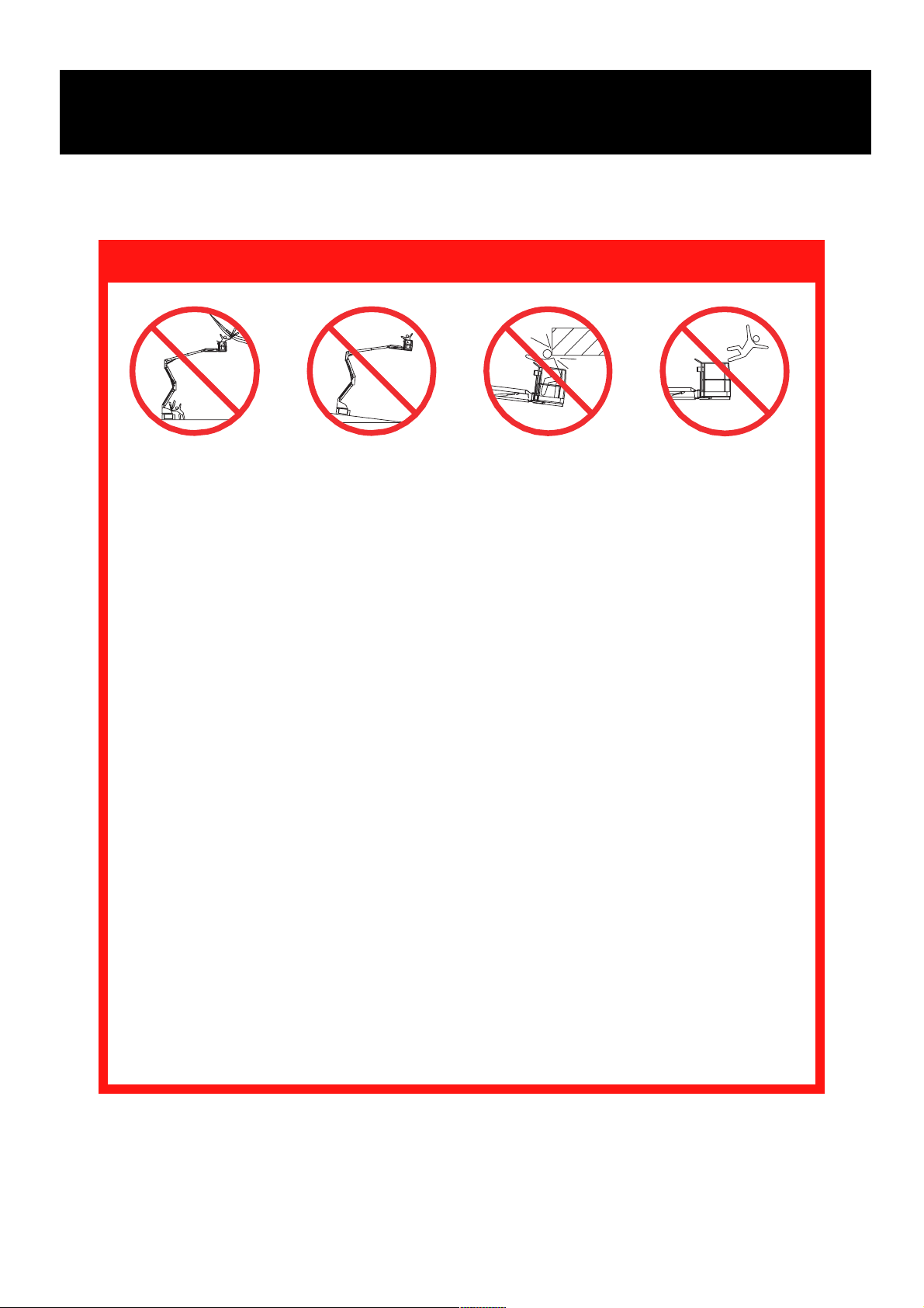
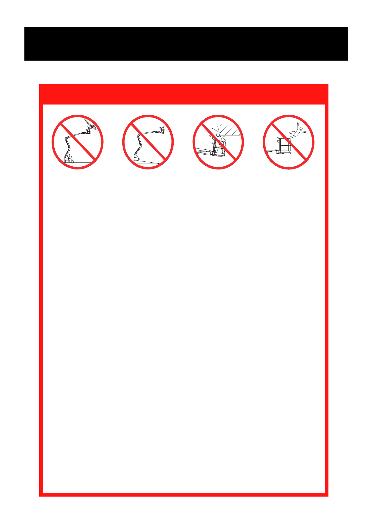
SAFETY RULES
Electrocution Hazard Tip Over Hazard Collision Hazard Fall Hazard
NEVER operate the
machine within ten (10)
feet of power lines. THIS
MACHINE IS NOT
INSULATED.
ALL occupants must wear an approved fall restraint properly attached to designated platform anchorage
point. Attach only one fall restraint to each anchorage point.
NEVER exceed maximum platform load of 500 lbs. (225 kg) and two (2) occupants.
NEVER exceed 45 lbs. (200 N) of side force per occupant.
NEVER Operate the machine when noise levels exceed 80 dB.
DISTRIBUTE all platform loads evenly on the platform.
NEVER operate the machine without first surveying the work area for surface hazards such as holes,
drop-offs, bumps, curbs, or debris; and avoiding them.
OPERATE machine only on surfaces capable of supporting wheel loads.
NEVER elevate the machine when wind speeds exceed 28 mph (12.5 m/sec.).
IN CASE OF EMERGENCY push emergency stop button to cut power to all machine functions.
ALWAYS close and secure gate after entering platform.
NEVER exit or enter platform while elevated.
NEVER use ladders, scaffolding, or other items to gain height; work only from the platform floor.
NEVER climb down elevating assembly while platform is elevated.
INSPECT the machine thoroughly for cracked welds, loose or missing hardware, hydraulic leaks, loose
wire connections, and damaged cables or hoses before using.
VERIFY that all labels are in place and legible before using.
NEVER use a machine that is damaged, not functioning properly, or has damaged or missing labels.
IF ALARM SOUNDS while boom is elevated, STOP, carefully retract boom and lower platform without
rotating. Move machine to a firm, level surface.
NEVER attach overhanging loads or use boom as a crane.
NEVER alter operating or safety systems without manufacturers written consent.
NEVER charge battery near sparks or open flame. Charging batteries emit explosive hydrogen gas.
NEVER replace any component or part with anything other than original UpRight replacement parts
without the manufacturer's written consent.
NEVER tow the machine. Transport by truck or trailer only.
AFTER USE, secure the work platform from unauthorized use by turning both keyswitches off and removing all keys.
NEVER operate the
boom or drive with
platform elevated
unless on firm level
surface.
NEVER position the
platform without first
checking for overhead
obstructions or other
hazards.
NEVER climb, stand or
sit on platform guardrails
or midrail.
2
Page 3

Introduction
This manual covers the operation of electric powered models of the AB-46 Articulated Boom. This
manual must be stored on the machine at all times.
Pre-Operation and Safety
Inspection
Carefully read, understand and follow all safety
rules, labels, and operating instructions, then
perform the following steps each day before use.
Perform a complete visual inspection of the entire
unit prior to operating. Check the following areas for
discrepancies:
1. Open panels and check hydraulic components /
hoses for damage or leaks. Check electrical
components / wiring for damage or loose connections.
2. Inspect chassis, axles, hubs, and steering linkage
for damage, deformation, buckled paint, loose or
missing hardware, and cracked welds.
3. Check tires for damage, punctures, and inflation;
tire pressure must be 75 psi.
4. Check all hoses / cables for wear.
5. Inspect elevating assembly for damage, deformation, buckled paint, loose or missing hardware,
and cracked welds.
6. Inspect platform and guardrails for damage,
deformation, buckled paint, loose or missing
hardware, and cracked welds. Insure that gate
operates freely and latches securely.
7. Check Hydraulic fluid level with platform fully
lowered.
8. Check battery fluid level (see battery maintenance, page 9).
DO NOT use a machine that is damaged or
malfunctioning. Tag and remove the unit
from service until it is repaired.
SYSTEM FUNCTION INSPECTION
Note: Refer to figures 1 and 2 for chassis and
platform control locations.
1. Before performing the following tests, check area
around machine and overhead for obstructions,
holes, drop-offs, and debris.
2. Turn chassis key switch to chassis, and turn on
(rotate clockwise) emergency stop switches at
the chassis control panel and at the platform
control panel.
3. Push in the chassis emergency stop button and
operate any function switch at the chassis control
panel, function should NOT activate. Repeat for
platform emergency stop button, operating
chassis controls. Return both emergency stop
switches to the on position.
4. Operate each function switch to raise / lower,
extend / retract, rotate left / right, each section of
the elevating assembly and observe the operation of the machine. All functions should operate
through full cycle smoothly.
5. Turn chassis key switch to platform.
6. Mount the platform, close and latch the gate, and
attach approved fall restraint to designated platform
anchorage point. Attach only one fall restraint to
each point.
7. Without depressing the foot switch, move the drive
control handle, machine should not function.
8. Depress the foot switch and move the drive
control handle forward and reverse. Observe
that proportional functions operate smoothly, and
that brakes apply quickly after control is released.
9. While depressing foot switch, operate steer
switch to left and right. Observe that steering
wheels turn properly.
10.While depressing foot switch, turn function speed
control knob to desired setting, and operate
boom controls. Observe that boom operates
smoothly, and that upper boom, jib, turret rotation, platform level, and platform rotation controls
operate proportionally in conjunction with function
speed control knob. Observe that platform
maintains level when boom is elevated.
11.With the upper boom elevated one foot, operate
drive control handle. Observe that drive speed is
limited to creep (1/2 foot [.15m] per second).
Lower upper boom to stowed position.
12.Press the service horn button. Observe that horn
is audible.
3
Page 4
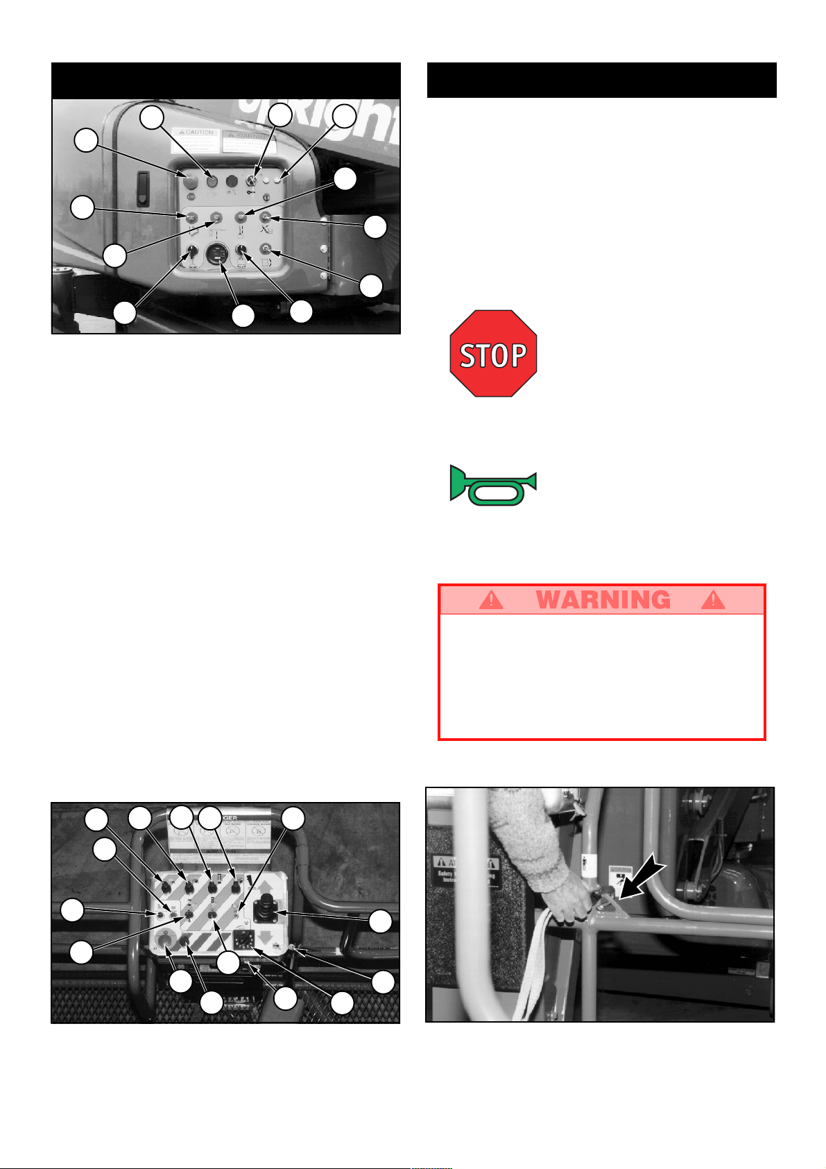
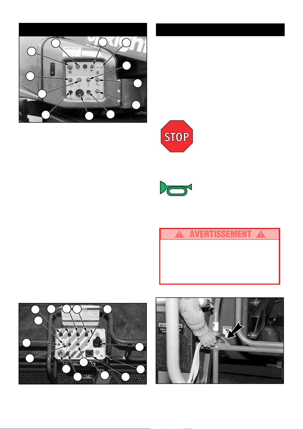
Controls and Indicators
Operation
2
1
6
7
10
Figure 1: Chassis Controls
Note: The following list corresponds to the
numbered items in figures one and two.
1. Emergency stop.
2. Electric motor start.
3. Low Voltage Indicator.
4. Keyswitch
5. Control fuses.
6. Riser control.
7. Upper boom control.
8. Boom extension control.
9. Jib control.
10.Turret rotation control.
11.Platform rotation control.
12.Platform level control.
13.Hourmeter.
14.Service horn button.
15.Drive control handle.
16.Function speed control.
17.Foot switch (located on platform floor).
18.Out of level indicator.
13
4
11
5
8
12
Before operating work platform insure that:
Pre-operation and safety inspection has been
completed, and any discrepancies have been
corrected.
The operator has been thoroughly trained on the
operation of the machine.
9
The work area is clear of all obstructions, holes,
drop-offs, or persons in the route of travel.
The surface is capable of supporting wheel loads.
Refer to figures one and two for control locations.
Emergency Stop
At any time during operation, press the emergency
stop button to stop all functions in an emergency.
Service Horn
At any time during operation, press the service horn
button to sound an audible warning if necessary.
Always wear an approved fall restraint
properly attached to designated platform
anchorage point when driving or elevating
the machine (see figure 3).
Attach only one fall restraint to each anchorage point.
18
10
8
6
7
3
Figure 2: Platform Controls
9
11
1
14
12
5
15
4
16
Figure 3: Typical Fall Restraint Anchorage Point
4
Page 5

POSITIONING THE PLATFORM
Driving
With Boom Lowered
1.
Turn chassis key switch to platform, and turn on
(turn clockwise) the chassis emergency stop switch.
2. Mount the platform, close and latch the gate.
3. Attach approved fall restraint to designated
platform anchorage point. Attach only one fall
restraint to each point.
4. Check that the area around and above the work
platform is clear of obstructions, holes, drop-offs,
persons in the route of travel, and the surface is
capable of supporting wheel loads.
5. Depress the foot switch and move the drive
control handle forward to travel forward and
reverse to travel in the reverse direction.
Note: When the boom is rotated to the front of
the chassis (steering wheels aft) directions of
travel and steering will be reversed. Observe the
color coded arrows on the control panel near the
drive control handle, and on the chassis. They
will indicate the direction of travel when the drive
control handle is moved.
With Boom Elevated
Travel with boom elevated is restricted to firm
level surfaces only.
When driving elevated, the machine will travel at
creep speed (1 foot [.3 m] per second).
Positioning the platform as close as possible to the
work area requires some planning. First, you must
survey the work site to find a suitable place to park
the machine. This must be a firm level area as close
as possible to the work area. Take into consideration all obstructions on the ground and overhead
and avoid them.
Once you have moved the machine to a firm level
surface as near as possible to the work area, follow
the instructions on the next page to position the
platform.
Always, before operating any function, check the
area around and overhead for any obstructions or
electrical conductors.
Multifunction Controls
The UpRight AB-46 employs the use of multifunction
controls. This means that riser or boom extension
will function at full speed while simultaneously
operating upper boom, jib, turret, or rotating the
platform.
The turret may be rotated while driving if necessary
to make turns in tight areas. All other boom functions will not operate while driving.
Lower Control Operation
All boom functions will operate at fixed speed.
1. Turn chassis keyswitch to chassis controls.
2. Operate boom control switches to position the
platform.
Steering
1. While depressing the foot switch, push the steering switch (located on top of the control handle) to
the left to turn left, and right to turn right.
Note: Steering is not self centering. Wheels
must be returned to the straight ahead position
by operating the steering switch.
5
Page 6
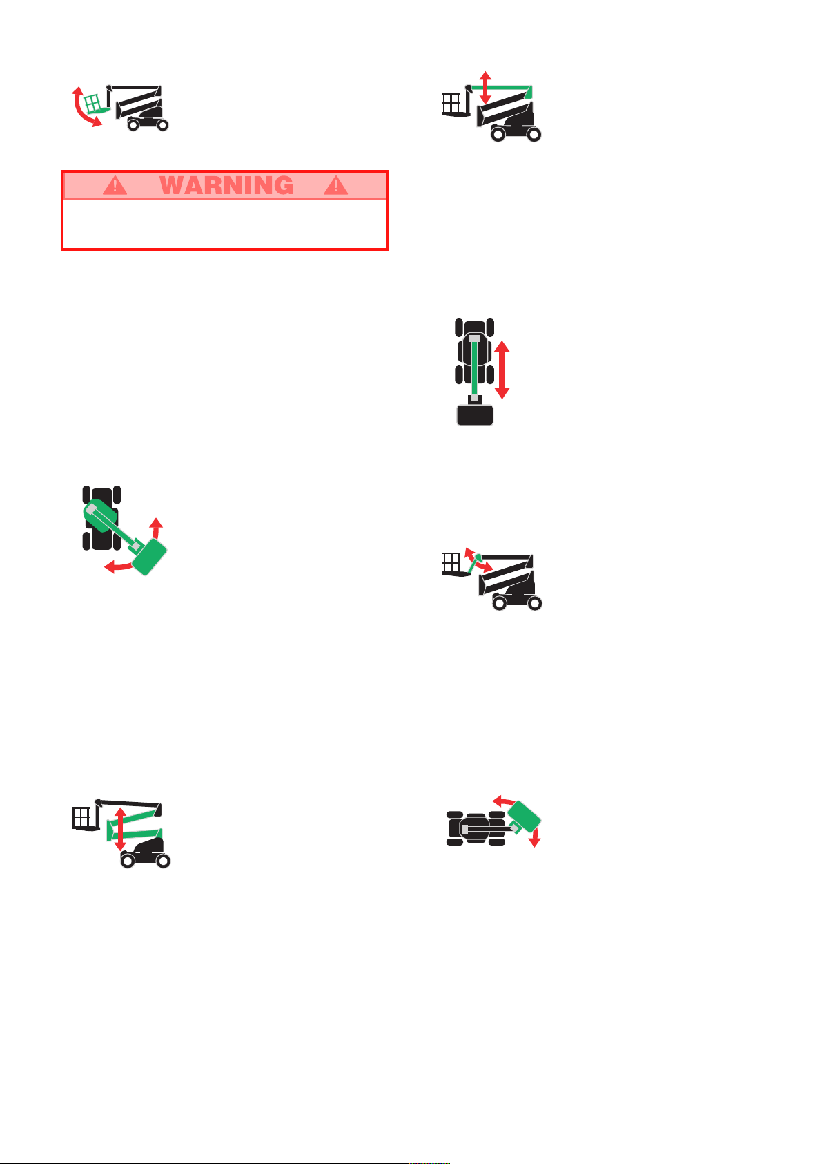
Leveling the Platform
DO NOT operate the machine if the platform
does not maintain level when elevated.
Note: Platform leveling can be performed only
with the boom stowed and should be done only
to calibrate the automatic leveling system.
1. Set the function speed control dial to the desired
setting. Rotate the dial clockwise to increase
speed, counterclockwise to decrease. If you are
not sure what speed to use, start out slow; the
speed can be varied while operating the function.
2. While depressing the foot switch, push the
platform level control switch forward to swing the
platform upward, rearward to swing the platform
downward. Release the switch to stop leveling.
Rotating the Turret
Elevating the Upper Boom
1. Set the function speed control dial to the desired
setting. Rotate the dial clockwise to increase
speed, counterclockwise to decrease. If you are
not sure what speed to use, start out slow; the
speed can be varied while operating the function.
2.
While depressing the foot switch, push the upper
boom control lever forward to elevate the upper
boom, rearward to lower the upper boom. Release
the control lever to stop elevating / lowering.
Extending the Upper Boom
1. While depressing the foot switch, push the boom
extension control lever rearward to extend the
boom, forward to retract the boom. Release the
control lever to stop extending / retracting. The
boom extension will function at a constant speed,
function speed control setting is not necessary.
1. Set the function speed control dial to the desired
setting. Rotate the dial clockwise to increase
speed, counterclockwise to decrease. If you are
not sure what speed to use, start out slow; the
speed can be varied while operating the function.
2. While depressing the foot switch, turn the turret
rotation control switch counterclockwise to rotate
left, clockwise to rotate right. Release the switch
to stop rotation. Observe the area around the
boom when rotating the turret to avoid any
obstructions.
Elevating the Riser
1. While depressing the foot switch, push the riser
control lever forward to elevate the riser, rearward to lower the riser. Release the control lever
to stop elevating / lowering. The riser will function at a constant speed, function speed control
setting is not necessary.
Elevating the Jib
1. Set the function speed control dial to the desired
setting. Rotate the dial clockwise to increase
speed, counterclockwise to decrease. If you are
not sure what speed to use, start out slow; the
speed can be varied while operating the function.
2. While depressing the foot switch, push the jib
control lever forward to elevate the jib, rearward
to lower the jib. Release the control lever to stop
elevating / lowering.
Rotating the Platform
1. Set the function speed control dial to the desired
setting. Rotate the dial clockwise to increase
speed, counterclockwise to decrease. If you are
not sure what speed to use, start out slow; the
speed can be varied while operating the function.
2. While depressing the foot switch, turn the platform rotation control switch counterclockwise to
rotate left, clockwise to rotate right. Release the
switch to stop rotation.
6
Page 7
EMERGENCY OPERATION
In the event of powered function failure, the elevating assembly may be lowered manually by the
following procedure.
Turret Rotation
Gear Box
NEVER climb down the elevating assembly.
If controls do not respond, ask someone on
the ground to lower the boom manually.
Lowering Elevating Assembly
1. Open the cover on the hydraulic module (opposite
side of the turret from the chassis control panel).
2. Remove the wire loop retainer from the hand
pump lever, and extend the handle upward to
gain leverage.
3. Operate the manual override (knurled knob) on the
appropriate valve (see fig. 4). Push in to lower /
extend, pull out to raise / retract as required.
4. While holding the appropriate valve in position,
pump the handle in and out until that section of
the elevating assembly is lowered / retracted.
5. Repeat as necessary operating each valve until
the elevating assembly is fully lowered.
Rotating Turret
1. Obtain a 7/8 inch ratcheting wrench.
2. Place the socket of the wrench onto the hex shaft
stub of the turret rotation gearbox.
3. Turn the wrench clockwise to rotate the turret
counterclockwise, turn counterclockwise to rotate
the turret clockwise.
7
/8 in. Ratcheting
Wrench
Figure 5: Manual Turret Rotation
EMERGENCY TOWING
Perform the following only when the machine will not
operate under its own power and it is necessary to
move the machine or when winching onto a trailer
for transportation.
The batteries must be connected to release the
brakes.
1. Insure that the platform is fully lowered, and that
the turret is rotated so the platform is to the rear
of the machine.
2. Attach chain / cable of sufficient strength for
towing the machine to front or rear tie down lugs.
3. Turn the keyswitch to the parking brake release
position. Alarm will sound.
4. Depress the electric motor start switch and hold
for 2 seconds, release.
5. After moving the machine, return the keyswitch to
the off position and remove the key to prevent
unauthorized operation.
Emergency control pump
Riser Valve
Extend Valve
Boom Valve
Jib Valve
Figure 4: Emergency Control Operation
DO NOT move the machine faster than
3 mph. Faster speeds will damage drive
components and void warranty.
AFTER USE EACH DAY
1. Ensure that the platform is fully lowered.
2. Park the machine on level ground, preferably
under cover, secure against vandals, children or
unauthorized operation.
3. Turn the key switch to OFF and remove all keys
to prevent unauthorized operation.
BATTERY CHARGING
See Maintenance, page 9.
7
Page 8
Transportation
BY CRANE
Stand clear of machine when lifting.
Check specifications on back page, insure
that crane and slings are of correct capacity
to lift weight of unit.
1. Insure that boom is fully lowered and retracted.
2. Attach straps to chassis lifting lugs only. Insure
that straps are adjusted properly to keep unit
level when lifting.
BY TRUCK OR TRAILER
1. Insure that boom is fully lowered and retracted.
2. Maneuver the machine onto bed of truck / trailer.
3. When winching, follow instructions for emergency
towing on page 7. Attach winch cable to front tie
down lugs.
Do not winch machine faster than 3 mph.
4. After winching, insure that brakes are set.
5. Secure the machine to the transport vehicle using
chains / straps of adequate load capacity (refer to
specifications, back page) attached to chassis tie
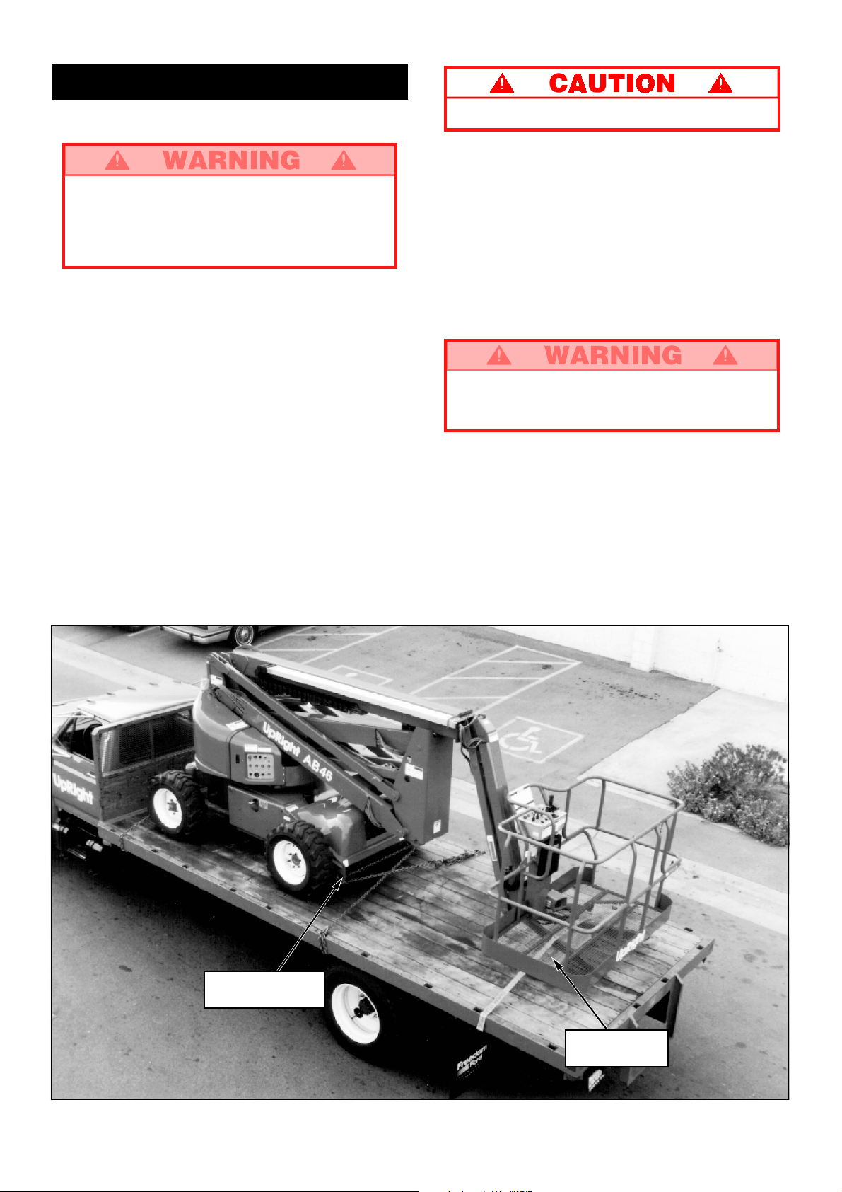
down lugs (see figure 6).
6. Place a wooden block (7.5" x 4" x 28") under
platform support braces as shown (see figure 6).
7. Attach ratchet strap; under platform floor grating,
over support braces (see figure 6). Tighten
securely, do not overtighten.
NEVER elevate the machine while on a truck
or trailer.
Chassis Tie Down /
Lifting Lug (typ.)
Figure 6: Securing the Machine for Transportation
Wooden Block
7.5" x 4" x 28"
8
Page 9
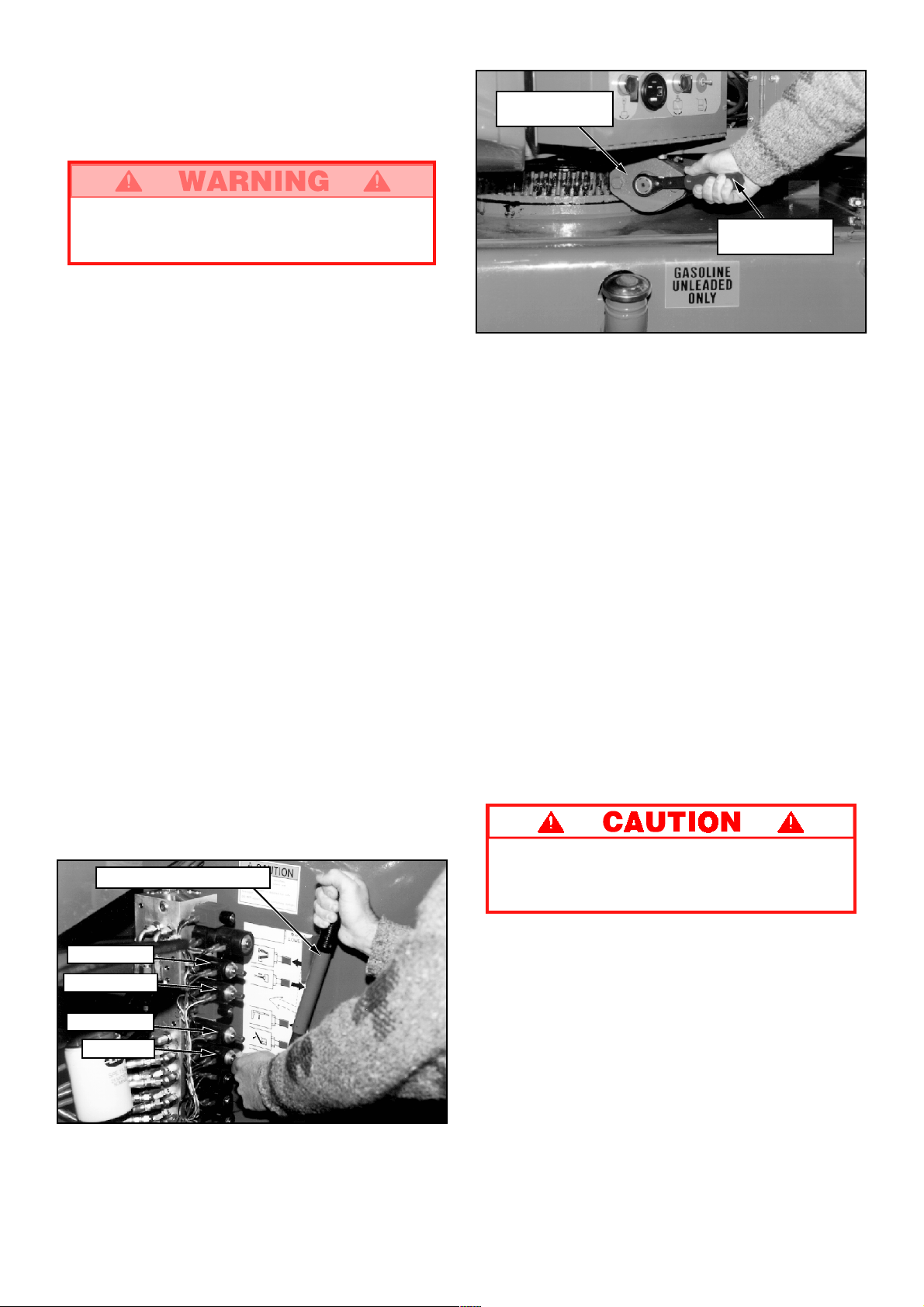
Maintenance
TIRES
Tire selection can affect the stability of the machine.
Use only tires supplied by UpRight unless approved
by the manufacturer in writing
BATTERY CHARGING
Charge batteries only in a well ventilated area.
Hazard of explosive gas mixture. Keep
sparks, flame and smoking materials away
from batteries.
Always wear safety glasses when working
with batteries.
Battery fluid is highly corrosive. Rinse away
any spilled fluid thoroughly with clean water.
Always replace batteries with UpRight
batteries or manufacturer approved replacements weighing 120 lbs. each.
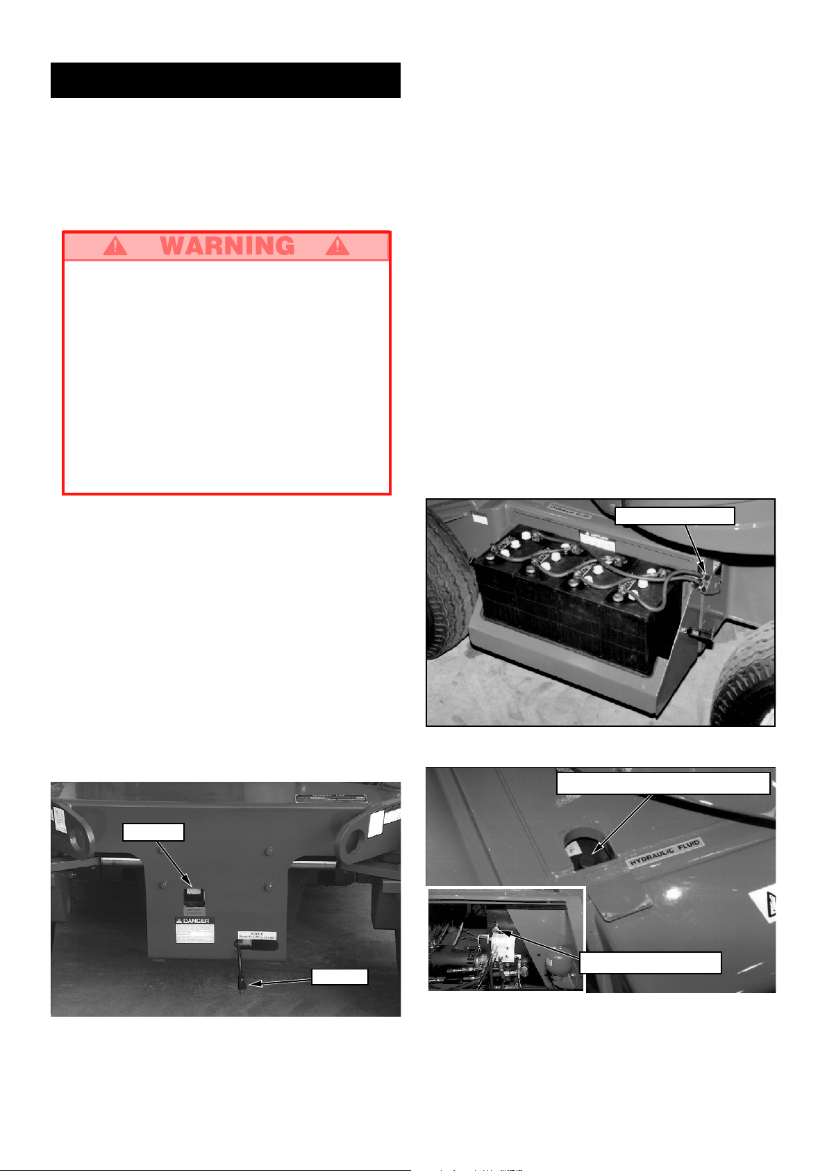
BATTERY MAINTENANCE
Check battery fluid level daily, especially if work
platform is being used in a warm, dry climate.
If electrolyte level is lower than
plates add distilled water only. DO NOT use tap
water it will shorten battery life.
Keep terminals and top of battery clean.
3
/8 in. (10 mm) above
HYDRAULIC OIL
1. Check oil level at sight gauge inside engine
compartment right hand side with the platform
fully lowered.
2. If necessary, fill to capacity with clean ISO 46
compatible hydraulic oil.
3. Lift flap located on top of chassis right side
(see figure 7).
4. Open filler / breather cap to add hydraulic oil.
5. Replace cap.
LUBRICATION
Refer to service manual for lubrication chart and
guidelines.
Charge batteries as follows:
1. Check the batteries fluid level. If the electrolyte
level is lower than
plates, add clean, distilled water only.
2. Verify charger voltage switch is set to the correct
voltage.
3. Connect extension cord (minimum 12 gauge
(1.5 mm²) conductor and maximum 50 ft. (15 m)
in length) to charger plug located through the
opening in front of the chassis (see figure 7).
Connect extension cord to properly grounded
outlet of proper voltage and frequency.
4. The charger will turn on automatically.
5. When the batteries are fully charged, the charger
will turn off automatically .
Ammeter
3
/8 in. (10 mm) above the
Battery Disconnect
Figure 8: Batteries (Typical Both Sides)
Hydraulic Oil Filler / Breather Cap
Figure 7: Battery Charger
Oil Level Sight Gauge
AC Cord
Figure 9: Hydraulic Oil Filler / Breather Cap and Oil
Level Sight Gauge
9
Page 10

ROUTINE SERVICE
Use the following table as a guide for routine maintenance. Inspection and maintenance shall be
performed by personnel who are trained and
familiar with mechanical and electrical procedures. Refer to the Service Manual for complete
service instructions.
Please copy this page and use the Routine Service
Table as a checklist when inspecting a machine for
service.
Routine Service Table
Routine Service Table Key
Interval
Daily = each shift (every day) or every eight hours
30
D
= every month (30 days) or every 50 hours
3
M
= every 3 months or 125 hours
6
M
= every 6 months or 250 hours
1
Y
= every year or 500 hours
2
Y
= every 2 years or 1000 hours
Y = Yes/Acceptable
N = No/Not Acceptable
R = Repaired/Acceptable
COMPONENT INSPECTION OR SERVICES INTERVAL Y N R
Battery Check electrolyte level Daily
System Check specific gravity 30
Hydraulic Check oil level Daily
Oil Change filter 6
Hydraulic Check for leaks Daily
System Check hose connections 30
Emergency Check operation of emergency override Daily
Hydraulic valves and hand pump
System Check operation of brake release hand pump Daily
Controller Check operation of all controls Daily
Control Check the exterior of the cable Daily
Cable for pinching, binding or wear
Platform Check fasteners for proper torque Daily
Floor and Check welds for cracks Daily
Rails Check condition of platform Daily
Tires Check for damage Daily
Hydraulic Wipe clean 30
Pump Check for leaks at mating surfaces 30
Steering Check fittings for proper torque 6
System Oil all pivot points 30
Electric Check electric drive motors for operation Daily
Drive System
Clean exterior 3
Check battery cable condition Daily
Clean terminals 3
Drain and replace with ISO 46 compatible oil 2
Check hoses for exterior wear 30
Check condition of anchorage points Daily
Check condition of operators manual Daily
Check air pressure (75 psi) Daily
Check lug nuts (torque to 90 ft. lbs. [123 Nm]) 30
Check for hose fitting leaks Daily
Check mounting bolts for proper torque 30
Check steering cylinder for leaks 30
Check linkage for wear areas 30
Check for missing / loose retainers Daily
Check cables, contactors, and connections Daily
D
M
M
M
Y
D
D
D
D
D
D
M
D
D
D
COMPONENT INSPECTION OR SERVICES INTERVAL Y N R
Elevating Inspect for structural cracks Daily
Assembly Check pivot points for wear 30
Chassis Check hoses for pinch or Daily
Turret Check ring gear for proper lubrication and wear Daily
Torque Check for leaks Daily
Hubs Check oil level 250H/6
Lift Check the cylinder rods for wear 30
Cylinders Check pivot pin retaining bolts 30
Entire Check for and repair Daily
Unit collision damage
Labels Check for peeling, missing, or unreadable Daily
Check pivot pin retaining bolts 30
for proper torque
Check members for deformation Daily
rubbing points
Check component mounting 6
for proper torque
Check welds for cracks Daily
Lubricate worm gear bearings 150H/3
Lubricate ring gear (MoS
Change oil after break-in period 50H/30
Change oil (SAE 90 wt. gear oil) 2000H/2
for proper torque
Check seals for leaks 30
Inspect pivot points for wear 30
Check fittings for proper torque 30
Check fasteners for proper torque 3
Check for corrosion, remove and repaint 3
Lubricate 30
labels & replace
grease) 150H/3
2
D
D
M
M
M
M
D
Y
D
D
D
D
D
M
M
D
Service Report
Date: _______________
Owner: _________________________________
Model No: ____________ Serial No: __________
Serviced By: _____________________________
Service Interval: __________________________
10
Page 11
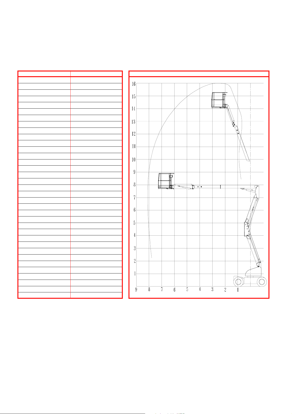
Specifications*
ITEM SPECIFICATION
Height
Working height maximum 16 m (52 ft.)
Platform height maximum 14 m (46 ft.)
Platform step in height 23 cm (9 in.)
Up and over height 7.62 m (25 ft.)
Drivable height 8 m (26 ft. 3 in.)
Horizontal outreach 7.46 m (24 ft. 6 in.)
Turret rotation 360 deg. non-continuous
Platform rotation 160 deg.
Tail swing None
Jib length 1.52 m (5 ft.)
Jib arc 140 deg.
Inside turning radius 61 cm (2 ft.)
Outside turning radius 3 m (9 ft. 10 in.)
Drive speed (lowered) 5.64 km/h (3.5 mph)
Drive speed (elevated) 1 km/h (.68 mph)
Gradeability 30%
Dimensions (boom stowed)
Platform Size 176 cm x 99 cm (69 in. x 39 in.)
Guardrail height 111 cm (43
Toeboards 15 cm (6 in.)
Maximum platform capacity 226 kg (500 lbs.)
Maximum no. of occupants 2
Weight 6 486 kg (14 300 lbs.)
Overall height 1.98 m (6 ft 6 in.)
Overall length 5.43 m (17 ft. 10 in.)
Overall width 1.6 m (5 ft. 9 in.)
Wheel base 1.85 m (73 in.)
Wheel track 1.5 m (59 in.)
Ground Clearance 15 cm (6 in.)
Power source Eight 6V, 350 AH Batteries
System voltage 48VDC
Maximum Hyd. Pressure 2400 psi
Controls Electric Proportional
Tires 9.5x16.5 10 ply highway tread
1
/2 in.)
REACH ENVELOPE DIAGRAM
DIMENSIONS IN METRES
* Specifications subject to change without notice.
Refer to Service Manual for complete parts and service information.
11
Page 12
Section française
CONSIGNES DE SÉCURITÉ
Danger délectrocution Danger de basculement Danger de collision Danger de chute
NE JAMAIS utiliser la
machine à moins de
3 mètres (10 pieds de
lignes dénergie électrique.
CETTE MACHINE
NEST PAS ISOLÉE.
TOUS les occupants doivent porter un dispositif antichute dun modèle approuvé, correctement fixé au point de
fixation désigné à cet effet de la plate-forme. Ne fixer quun dispositif antichute par point de fixation.
NE JAMAIS dépasser la charge maximale de la plate-forme, établie à 225 kg (500 lb) et à deux (2) occupants.
NE JAMAIS dépasser une force latérale par occupant de 200 N (45 lb).
NE JAMAIS utiliser la machine dans un environnement où le niveau de bruit dépasse 80 dB.
RÉPARTIR également toutes les charges sur la plate-forme.
NE JAMAIS utiliser la machine sans avoir dabord vérifié si la surface de la zone de travail ne présente pas de
dangers tels que des trous, des dénivellations, des bosses, des bordures ou des débris et sans sêtre assuré
quon peut les éviter.
NE faire fonctionner la machine QUE sur des surfaces pouvant supporter la charge des roues.
NE JAMAIS élever la plate-forme lorsque la vitesse du vent dépasse 12,5 m/s (28 mi/h).
EN CAS DURGENCE, appuyer sur le bouton darrêt durgence pour couper toute alimentation aux fonctions de
la marche.
TOUJOURS fermer au loquet le portillon après être monté sur la plate-forme.
NE JAMAIS tenter de descendre de la plate-forme ni tenter dy monter lorsquelle est élevée.
NE JAMAIS dresser déchelle, déchafaudage ni dautres objets permettant de prendre de la hauteur ; toujours
travailler à partir du plancher de la plate-forme.
NE JAMAIS descendre par le dispositif délévation lorsque la plate-forme est élevée.
VÉRIFIER la machine à fond, avant de lutiliser, afin dy déceler toute soudure fissurée, toute pièce de fixation
ayant du jeu ou qui manquerait, toute fuite du circuit hydraulique, toute connexion lâche et tout câble ou tuyau
qui serait endommagé.
SASSURER que toutes les étiquettes sont en place et bien lisibles avant dutiliser la machine.
NE JAMAIS utiliser une machine qui est endommagée, qui ne fonctionne pas correctement, ou dont les éti-
quettes sont endommagées ou manquantes.
SI LALARME RETENTIT alors que la flèche est élevée, ARRÊTER, rentrer la flèche avec précaution, et
abaisser la plate-forme sans faire pivoter la machine. Amener la machine jusque sur une surface horizontale
solide.
NE JAMAIS fixer une charge qui déborde ni utiliser la flèche comme une grue.
NE JAMAIS modifier les dispositifs dexploitation ou de sécurité de la machine sans le consentement écrit
préalable du fabricant.
NE JAMAIS charger la batterie daccumulateurs près dune flamme ou dune source détincelles : les batteries
dégagent de lhydrogène gazeux explosif lorsquelles rechargent.
NE JAMAIS remplacer quelque élément ou quelque pièce que ce soit par autre chose quune pièce dorigine
UpRight sans le consentement écrit du fabricant.
NE JAMAIS remorquer la machine : ne la transporter quà bord dun camion ou dune remorque.
APRÈS AVOIR UTILISÉ la plate-forme élévatrice, tourner les deux clés de linterrupteur à la position darrêt («
OFF »), puis les retirer afin de prévenir lutilisation de la plate-forme par toute personne non autorisée.
NE JAMAIS utiliser le
bras articulé à flèche
ni conduire plateforme élevée sans
que la machine ne
soit sur une surface
horizontale solide.
NE JAMAIS positionner
la plate-forme sans
sêtre dabord assuré
quil ny a pas
dobstacles ou autres
sources de danger aux
alentours.
NE JAMAIS monter,
sasseoir ou se tenir
debout sur les rampes
du garde-corps.
12
Page 13

Introduction
Ce manuel se rapporte à lutilisation des modèles à
alimentation électrique de bras articulé à flèche AB-46.
On veillera à le garder sur la machine en tout temps.
Vérification préliminaire de
sécurité et dutilisation
Lire dabord attentivement toutes les règles de
sécurité, les étiquettes et le mode demploi, en
sassurant de les comprendre et de sy conformer.
Chaque jour avant dutiliser la machine, exécuter les
tâches suivantes :
Effectuer une inspection visuelle complète de la machine
avant de lutiliser. Porter une attention particulière aux
points suivants :
1. Ouvrir les panneaux, et vérifier que les composants
des circuits hydrauliques/les tuyaux ne présentent pas
de fuites ni de dommages. Vérifier quaucun
composant/filage électrique ne présente de
dommages ni de connexions ayant du jeu.
2. Vérifier à fond le châssis, les essieux, les moyeux et la
timonerie de direction pour sassurer quils ne
présentent pas de dommages, de déformations, de
peinture gondolée, de pièces de fixation ayant du jeu
ou qui manquent, ni de soudures fissurées.
3. Vérifier si les pneus sont endommagés, perforés ou
mal gonflés ; la pression de gonflage doit être de
5,1 bars (75 lb/po2).
4. Vérifier tous les tuyaux/les câbles pour sassurer quils
ne sont pas usés.
5. Vérifier à fond le dispositif délévation pour sassurer
quil ne présente pas de dommages, de déformations,
de peinture gondolée, de pièces de fixation ayant du
jeu ou qui manquent, ni de soudures fissurées.
6. Vérifier à fond la plate-forme et les garde-corps pour
sassurer quils ne présentent pas de dommages, de
déformations, de peinture gondolée, de pièces de
fixation ayant du jeu ou qui manquent, ni de soudures
fissurées. Sassurer que le portillon fonctionne librement et se ferme au loquet fermement.
7. La plate-forme étant abaissée complètement, vérifier
le niveau dhuile hydraulique.
8. Vérifier le niveau délectrolyte de la batterie. (Voir «
Entretien de la batterie », à la page 19.)
NE PAS utiliser la machine si elle est endommagée ou en mauvais état de fonctionnement.
Apposer une étiquette volante sur la machine et la
retirer du service jusquà ce quelle ait été réparée.
ESSAI DE FONCTIONNEMENT
DES ÉLÉMENTS
Nota : Se reporter aux figures 1 et 2 pour obtenir les
emplacements du pupitre de commande sur le
châssis et sur la plate-forme.
1. Avant deffectuer les essais suivants, vérifier dabord
que laire qui entoure la machine ne présente pas de
dangers tels que des obstacles en surplomb, des
trous, des dénivellations et des débris.
2. Tourner linterrupteur à clé du boîtier de commande à
la position de châssis (« CHASSIS »), puis faire
tourner dans le sens horaire les interrupteurs darrêt
durgence au tableau de commande monté sur le
châssis ainsi quau tableau de commande monté sur
la plate-forme.
3. Enfoncer le bouton darrêt durgence du châssis, puis
actionner nimporte quel interrupteur de fonction au
tableau de commande monté sur le châssis :
AUCUNE fonction NE devrait être active. Répéter la
marche à suivre avec le bouton darrêt durgence de la
plate-forme, pour activer les commandes du châssis.
Ramener les deux interrupteurs darrêt à la position «
ON ».
4. Mettre en marche chaque interrupteur de fonction pour
élever/abaisser, déployer/rentrer, faire pivoter à
gauche/à droite, chaque section du dispositif délévation, et observer le fonctionnement de la machine.
Toutes les fonctions devraient effectuer le cycle
complet en douceur.
5. Tourner linterrupteur à clé du châssis à la position de
plate-forme (« PLATFORM »).
6. Monter sur la plate-forme, fermer le portillon au loquet
et fixer le dispositif antichute approuvé au point de
fixation désigné de la plate-forme. Ne fixer quun seul
dispositif antichute par point de fixation.
7. Sans enfoncer linterrupteur à pédale, déplacer le
levier de direction : la machine devrait rester immobile.
8. Enfoncer linterrupteur à pédale, et déplacer le levier
de direction en avant, puis en arrière. Noter si les
fonctions proportionnelles se déroulent en douceur et
si les freins sappliquent rapidement une fois la
commande relâchée.
9. Tout en enfonçant linterrupteur à pédale, actionner le
bouton de commande de direction vers la gauche et
vers la droite. Noter si les roues directrices braquent
correctement.
10. Tout en enfonçant linterrupteur à pédale, tourner le
bouton de commande de vitesse des fonctions au
réglage voulu, et faire fonctionner les commandes du
bras articulé à flèche. Noter si le bras articulé à flèche
fonctionne en douceur et si les commandes de la
flèche, du bras en porte-à-faux, de rotation du revolver, du positionnement horizontal de la plate-forme et
de la rotation de la plate-forme fonctionnent de façon
proportionnelle, conjointement avec la manoeuvre du
bouton de commande de vitesse des fonctions. Noter
si la plate-forme se maintient de niveau lorsque le
bras articulé à flèche est élevé.
11. La flèche étant élevée de 30 cm (1 pi), manoeuvrer le
levier de direction. Noter si la vitesse davance est
limitée à la marche extra-lente (0,15 m [6 po] à la
seconde). Abaisser la flèche en position escamotée.
12. Appuyer sur le bouton de la sirène dappel. Noter si le
timbre retentit.
13
Page 14
Commandes et indicateurs
Mode demploi
2
4
5
1
8
6
9
7
12
10
Figure 1 : Emplacement des commandes
sur le châssis
Nota : La liste suivante correspond aux accessoires
indiqués par un numéro dans les figures 1 et 2.
1. Bouton darrêt durgence
2. Bouton de démarrage du moteur
3. Voyant de basse tension
4. Interrupteur à clé
5. Fusibles des circuits de commande
6. Commande du bras articulé de soulèvement
7. Commande de la flèche
8. Commande de la rallonge de flèche
9. Commande du bras en porte-à-faux
10. Commande de rotation du revolver
11. Commande de rotation de la plate-forme
12. Commande de positionnement horizontal
de la plate-forme
13. Horomètre
14. Bouton de la sirène dappel
15. Levier de direction
16. Commande de v
17. Interrupteur à pédale (situé sur le plancher
de la plate-forme)
18. Voyant dinclinaison
itesse des fonctions
13
11
Avant dutiliser la plate-forme élévatrice, sassurer :
Que la vérification préliminaire de sécurité et
dutilisation a été effectuée, et que tout écart noté
est corrigé.
Que lopérateur a reçu une formation pratique qui lui
a permis de bien connaître lutilisation de la machine.
Que laire de travail est exempte de tout obstacle, de
tout trou/dénivellation et de toute personne qui se
trouverait sur la voie de passage.
Que la surface peut supporter la charge des roues.
Voir les emplacements des commandes aux figures 1 et 2.
Arrêt durgence
En tout temps pendant lutilisation, lorsquune situation
durgence se présente, appuyer sur le bouton darrêt
durgence pour arrêter toutes les fonctions.
Sirène dappel
En tout temps pendant lutilisation, appuyer sur le bouton
de sirène dappel pour faire retentir une alarme sonore, si
nécessaire.
Toujours porter un dispositif antichute approuvé,
fixé correctement au point de fixation désigné de
la plate-forme, pendant la conduite ou lélévation
de la machine (voir figure 3).
Ne fixer quun seul dispositif antichute par point
de fixation.
8
6
7
9
12
3
18
10
11
1
14
Figure 2 : Emplacement des commandes
sur la plate-forme
5
15
4
16
Figure 3 : Point de fixation type
pour dispositif antichute
14
Page 15

Conduite
Bras articulé à flèche baissé
1. Tourner linterrupteur à clé du tableau de commande
monté sur le châssis à la position plate-forme
(« PLATFORM »), puis régler à la position « ON »
(tourner dans le sens horaire) linterrupteur darrêt
durgence du châssis.
2. Monter sur la plate-forme et fermer le portillon au
loquet.
3. Fixer le dispositif antichute approuvé au point de
fixation désigné de la plate-forme. Nattacher quun
seul dispositif antichute par point dattache.
4. Vérifier que laire de travail est exempte de tout
obstacle, de tout trou/dénivellation et de toute personne qui se trouverait sur la voie de passage, et que
la surface peut supporter la charge des roues.
5. Enfoncer du pied linterrupteur à pédale, et amener le
levier de direction en avant pour se diriger en marche
avant, ou en arrière, pour se diriger en marche arrière.
Nota : Lorsque le bras articulé à flèche a pivoté à
lavant du châssis (roues directrices à larrière), les
sens de marche se trouvent inversés par rapport à la
position du levier de direction. Noter les flèches à
code de couleur qui se trouvent sur le tableau de
commande, près du levier de direction, ainsi que sur
le châssis : elles indiquent le sens de la marche
commandé par le levier de direction.
Bras articulé à flèche élevé
Les déplacements bras articulé à flèche élevé se
limitent exclusivement aux surfaces horizontales
solides.
En conduite bras articulé à flèche élevé, la machine
navance quen marche extra-lente (0,3 m [1 pi] à la
seconde).
POSITIONNEMENT DE
LA PLATE-FORME
Une certaine planification préalable est nécessaire pour
positionner la plate-forme le plus près possible de laire de
travail. Il faut dabord étudier le chantier afin de trouver un
endroit convenable pour garer la machine ; ce doit être un
lieu à surface horizontale solide, situé le plus près possible de laire de travail. Tenir compte de tous les obstacles
qui peuvent se trouver au sol ou en hauteur, et les éviter.
Une fois la machine garée sur une surface horizontale
solide, le plus près possible de laire de travail, suivre les
consignes données à la page suivante pour positionner la
plate-forme.
Avant de commander une fonction quelconque, toujours
vérifier pour sassurer quil ny a aucun obstacle ni
conducteur électrique autour et au-dessus de la machine.
Commandes multifonctions
Le modèle UpRight AB-46 utilise des commandes
multifonctions. Cela signifie que la commande du bras
articulé de soulèvement ou de la rallonge télescopique
de la flèche fonctionnera à pleine vitesse, de façon
simultanée avec la commande de la flèche, du bras en
porte-à-faux, du revolver ou de la rotation de la
plate-forme.
Au besoin, on peut faire pivoter le revolver tout en
conduisant pour effectuer des virages à létroit. Aucune
autre fonction du bras articulé à flèche ne sera
opérationnelle durant la marche.
Fonctionnement du tableau de
commande monté sur le châssis
Toutes les fonctions du bras articulé à flèche seront
opérationnelles à vitesse fixe.
1. Tourner linterrupteur à clé du tableau de commande
monté sur le châssis.
2. Manoeuvrer les interrupteurs de commande de la
flèche pour positionner la plate-forme.
Commande de direction
1. Tout en enfonçant du pied linterrupteur à pédale,
déplacer le bouton de commande de direction (qui se
trouve sur le dessus du levier de commande) vers la
gauche pour virer à gauche, ou vers la droite pour
virer à droite.
Nota : La direction nest pas de type à centrage
automatique : pour ramener les roues tout droit,
actionner le bouton de commande de direction.
15
Page 16

Mise de niveau de la
plate-forme
NE PAS utiliser la machine si la plate-forme ne se
maintient pas de niveau lorsque élevée.
Nota : La mise de niveau de la plate-forme ne peut
être exécutée que si le bras articulé à flèche est
escamoté, et elle ne devrait être exécutée que dans
le but détalonner le système de mise de niveau
automatique.
1. Régler le cadran de commande de vitesse à la
position désirée. Tourner le cadran dans le sens
horaire pour augmenter la vitesse et dans le sens
antihoraire pour la diminuer. À défaut de savoir quelle
vitesse utiliser, commencer par la marche lente ; la
vitesse peut être augmentée pendant la manoeuvre.
2. Tout en enfonçant du pied linterrupteur à pédale,
amener le bouton de commande de positionnement
horizontal de la plate-forme en avant pour envoyer la
plate-forme vers le haut, et le ramener en arrière pour
envoyer la plate-forme vers le bas. Relâcher le bouton
de commande pour arrêter la manoeuvre de mise de
niveau.
Rotation du revolver
Élévation de la flèche
1. Régler le cadran de commande de vitesse à la
position désirée. Tourner le cadran dans le sens
horaire pour augmenter la vitesse et dans le sens
antihoraire pour la diminuer. À défaut de savoir quelle
vitesse utiliser, commencer par la marche lente ; la
vitesse peut être augmentée pendant la manoeuvre.
2. Tout en enfonçant du pied linterrupteur à pédale,
amener le levier de commande de la flèche vers
lavant pour élever le flèche, et lamener vers larrière
pour abaisser la flèche. Relâcher le levier de commande pour arrêter la manoeuvre délévation/
dabaissement.
Déploiement
de la flèche
1. Tout en enfonçant du pied linterrupteur à pédale,
amener vers larrière le levier de commande de la
rallonge de flèche pour déployer la flèche, lamener
vers lavant pour escamoter la flèche. Relâcher le
levier de commande pour arrêter la manoeuvre de
déploiement/descamotage. Le déploiement de la
flèche fonctionnera à une vitesse constant; il nest
pas nécessaire de régler la commande de vitesse des
fonctions.
1. Régler le cadran de commande de vitesse à la
position désirée. Tourner le cadran dans le sens
horaire pour augmenter la vitesse et dans le sens
antihoraire pour la diminuer. À défaut de savoir quelle
vitesse utiliser, commencer par la marche lente ; la
vitesse peut être augmentée pendant la manoeuvre.
2. Tout en enfonçant du pied linterrupteur à pédale,
tourner le bouton de commande de rotation du
revolver dans le sens antihoraire pour faire tourner le
revolver vers la gauche et dans le sens horaire pour le
faire tourner vers la droite. Relâcher linterrupteur pour
arrêter la rotation. Surveiller laire entourant la flèche
pendant la manoeuvre afin déviter tout obstacle.
Élévation du bras
articulé de soulèvement
1. Tout en enfonçant du pied linterrupteur à pédale,
amener vers lavant le levier de commande du bras
articulé de soulèvement pour élever le bras, et lamener vers larrière pour labaisser. Relâcher le levier de
commande pour arrêter lélévation/labaissement. Le
bras articulé de soulèvement fonctionne à une vitesse
constante ; il nest pas nécessaire de régler la commande de vitesse des fonctions.
Élévation du bras
en porte-à-faux
1. Régler le cadran de commande de vitesse à la
position désirée. Tourner le cadran dans le sens
horaire pour augmenter la vitesse et dans le sens
antihoraire pour la diminuer. À défaut de savoir quelle
vitesse utiliser, commencer par la marche lente ; la
vitesse peut être augmentée pendant la manoeuvre.
2. Tout en enfonçant du pied linterrupteur à pédale,
amener le levier de commande du bras en porte-àfaux vers lavant pour élever le bras en porte-à-faux,
et lamener vers larrière pour abaisser le bras.
Relâcher le levier de commande pour arrêter la
manoeuvre délévation/dabaissement.
Rotation de
la plate-forme
1. Régler le cadran de commande de vitesse à la
position désirée. Tourner le cadran dans le sens
horaire pour augmenter la vitesse et dans le sens
antihoraire pour la diminuer. À défaut de savoir quelle
vitesse utiliser, commencer par la marche lente ; la
vitesse peut être augmentée pendant la manoeuvre.
2. Tout en enfonçant linterrupteur à pédale, tourner le
bouton de commande de rotation de la plate-forme
dans le sens antihoraire, pour commander la rotation
vers la gauche, ou dans le sens horaire, pour commander la rotation vers la droite. Relâcher le bouton
de commande pour arrêter la manoeuvre de rotation.
16
Page 17

FONCTIONNEMENT DE SECOURS
En cas de panne des fonctions alimentées à lélectricité, il
est possible dabaisser manuellement le dispositif délévation en observant la marche à suivre ci-après.
NE JAMAIS descendre du dispositif délévation en
position élevée. Si les commandes ne répondent
pas, demander à quelquun se trouvant au sol
dabaisser le bras articulé à flèche manuellement.
Abaissement du dispositif délévation
1. Ouvrir le couvercle du module hydraulique (à lopposé
du revolver, à partir du tableau de commande monté
sur le châssis).
2. Enlever le fil de retenue en boucle du levier de pompe
à bras, puis déployer la poignée vers le haut pour
accroître leffet de levier.
3. Actionner la commande manuelle prioritaire (bouton
moleté) sur la soupape appropriée (voir figure 4).
Enfoncer pour abaisser/déployer ; tirer pour élever/
rentrer, au besoin.
4. Tout en maintenant la soupape appropriée en position,
« pomper » la poignée de haut en bas jusquà ce que
cette section du dispositif délévation soit abaissée/
escamotée.
5. Répéter au besoin, en actionnant chaque soupape
jusquà ce que le dispositif délévation soit complètement abaissé.
Rotation du revolver
1. Obtenir une clé à rochet de 7/8 po.
2. Placer la douille de la clé sur lergot à fût à six pans de
la boîte dengrenages du revolver.
3. Tourner la clé dans le sens horaire pour faire tourner
le revolver dans le sens antihoraire, et tourner la clé
dans le sens antihoraire pour faire tourner le revolver
dans le sens horaire.
Boîte
dengrenages
du revolver
Clé à rochet
7
/8 po
de
Figure 5 : Commande de manuelle
de rotation du revolver
REMORQUAGE DE SECOURS
Nexécuter les opérations suivantes que lorsque la
machine refuse de fonctionner de façon autonome et quil
est nécessaire de la déplacer, ou lorsquon veut la hisser
au treuil sur une remorque pour fin de transport.
Les batteries daccumulateurs doivent être connectées
pour permettre de relâcher les freins.
1. Sassurer que la plate-forme est complètement
abaissée et que le revolver est tourné de telle sorte
que la plate-forme se trouve à larrière de la machine.
2. Fixer une chaîne/un câble suffisamment résistant pour
remorquer la machine aux étriers darrimage avant ou
arrière.
3. Tourner linterrupteur à clé à la position de relâchement du frein de stationnement (« PARKING BRAKE
RELEASE »). Lalarme retentira.
4. Enfoncer le bouton de démarrage du moteur et le
maintenir ainsi pendant 2 secondes, puis le relâcher.
5. Après avoir déplacé la machine, ramener linterrupteur
à clé à la position darrêt « OFF », puis retirer la clé
afin déviter toute utilisation non autorisée.
Pompe à bras
de secours
Soupape du
bras articulé de
soulèvement
Soupape de la
rallonge de flèche
Soupape de
la flèche
Soupape
du bras en
porte-en-faux
Figure 4 : Utilisation de la commande de secours
NE PAS faire avancer la machine à une vitesse
supérieure à 5 km/h (3 mi/h). Un déplacement à
une vitesse supérieure à celle-ci endommagera
les composants dentraînement et annulera la
garantie.
APRÈS UTILISATION,
TOUS LES JOURS
1. Abaisser la plate-forme complètement.
2. Stationner la machine sur une surface plane,
préférablement à labri des vandales, des enfants et
de toute personne qui pourrait éventuellement sen
servir sans autorisation.
3. Tourner la clé de linterrupteur à la position darrêt
« OFF », puis la retirer afin de prévenir toute utilisation
non autorisée de la machine.
RECHARGE DES BATTERIES
Voir Entretien, en page 19.
17
Page 18

Transport
PAR GRUE
Se tenir à lécart de la machine pendant la
manoeuvre de levage.
Vérifier les caractéristiques techniques au dos
pour sassurer que la grue et les élingues sont
dune capacité suffisante pour lever la masse de
la machine.
1. Sassurer que la flèche est complètement abaissée et
escamotée.
2. Fixer des sangles aux étriers de levage du châssis
seulement. Sassurer que les sangles sont réglées à
une tension suffisante pour maintenir la machine de
niveau au cours de la manoeuvre de levage.
PAR CAMION OU REMORQUE
1. Sassurer que la flèche est complètement abaissée et
escamotée.
2. Manoeuvrer la machine jusque sur la plate-forme du
camion/de la remorque.
3. Pour lever au treuil, suivre les consignes de remorquage de secours fournies à la page 17. Fixer le câble
du treuil aux étriers darrimage avant.
Ne pas déplacer la machine au treuil à plus de 5
km/h (3 mi/h).
4. Après le remorquage au treuil, sassurer que les freins
sont bien serrés.
5. Arrimer la machine sur le véhicule de transport au
moyen de chaînes ou de sangles dune capacité de
charge suffisante (se reporter aux caractéristiques
techniques, au dos), fixées aux étriers darrimage du
châssis (voir figure 6).
6. Placer un bloc de bois de 19 cm x 10 cm x 71 cm
(7,5 po x 4 po x 28 po) sous les poutrelles supports
de la plate-forme de la machine, comme le montre
la figure 6.
7. Attacher la sangle à cliquet sous le plancher grillé de
la plate-forme, par-dessus les poutrelles supports (voir
figure 6). Attacher fermement, sans serrer à lexcès.
NE JAMAIS élever le bras articulé à flèche
lorsque la machine se trouve sur une plate-forme
de camion ou une remorque.
Étrier darrimage-levage
du châssis (type)
Figure 6 : Arrimage de la machine pour fin de transport
bloc de bois de
19 cm x 10 cm x 71 cm
(7,5 po x 4 po x 28 po)
18
Page 19

Entretien
PNEUS
Le choix des pneus peut influer sur la stabilité de la
machine. Nutiliser que des pneus fournis par UpRight,
sauf approbation écrite à leffet contraire émise par le
fabricant.
RECHARGE DES BATTERIES
Ne charger les batteries que dans un endroit bien
ventilé.
Risque démanations gazeuses explosives. Tenir
la batterie à lécart détincelles, de flammes et de
toute source de chaleur extrême.
Ne jamais manipuler les batteries sans porter de
lunettes de sécurité.
Lélectrolyte (liquide de la batterie) est un liquide
très corrosif. Éliminer toute trace de liquide
déversé de la batterie en rinçant à grande eau
claire.
Toujours remplacer les batteries par des batteries
UpRight ou de rechange approuvées par le
fabricant et pesant 55 kg (120 lb) chacune.
ENTRETIEN DES BATTERIES
Vérifier le niveau délectrolyte tous les jours, surtout si la
machine est utilisée sous les climats chauds et secs.
Si lélectrolyte ne recouvre pas les plaques de batterie
dau moins 10 mm (3/8 po), ajouter de leau distillée
seulement. NE PAS utiliser de leau du robinet, sinon la
vie utile des batteries sera raccourcie
Garder les bornes et le dessus des batteries propres.
HUILE HYDRAULIQUE
1. Vérifier le niveau de lhuile hydraulique par la jauge de
niveau de lintérieur du compartiment moteur, à droite,
la plate-forme étant complètement abaissée.
2. Si nécessaire, faire lappoint du réservoir pour le
remplir avec une huile hydraulique compatible ISO 46.
3. Soulever le rabat situé sur le dessus du châssis, à
droite (voir figure 7).
4. Ouvrir le bouchon reniflard pour ajouter lhuile
hydraulique.
5. Remettre le bouchon en place.
LUBRIFICATION
Voir la table de lubrification et les lignes directrices
appropriées dans le Manuel dentretien.
Charger les batteries comme suit :
1. Vérifier le niveau délectrolyte des batteries. Si
lélectrolyte ne recouvre pas les plaques de batterie
dau moins 10 mm (3/8 po), ajouter de leau distillée
propre seulement.
2. Vérifier le sélecteur de tension du chargeur pour
sassurer quil est réglé à la tension correcte.
3. Brancher le câble de rallonge (conducteur de calibre
minimum 12 (1,5 mm²), dune longueur maximum de
15 m [50 pi]) à la prise de chargeur, que lon trouve
dans louverture à lavant du châssis (figure 7).
Brancher lautre extrémité du câble de rallonge à une
prise électrique dune tension et dune fréquence
appropriées.
4. Le chargeur sallumera automatiquement.
5. Lorsque les batteries sont complètement chargées,
le chargeur séteint automatiquement.
Ampèremètre
Déconnexion de la batterie
Figure 8 : Batteries daccumulateurs
(types, des deux côtés)
Bouchon reniflard de lorifice de
remplissage du réservoir dhuile
dalimentation c.a.
Figure 7 : Chargeur de batteries
Cordon
Jauge de niveau dhuile
hydraulique à fenêtre
Figure 9 : Bouchon reniflard de lorifice de
remplissage du réservoir dhuile hydraulique et
jauge de niveau dhuile hydraulique à fenêtre
19
Page 20

ENTRETIEN COURANT
Le tableau ci-après sert de guide pour lentretien courant.
Seules les personnes formées qui connaissent les
opérations mécaniques et électriques doivent réaliser
la vérification de contrôle et lentretien de la machine.
Les consignes dentretien se trouvent dans le Manuel
dentretien.
Au moment de vérifier la machine, reproduire cette
page et utiliser le tableau qui sy trouve comme liste de
vérification.
Tableau dentretien courant
Légende du tableau
Périodicité
Quot. = chaque quart de travail (quotidiennement)
ou toutes les 8 heures
30J = tous les mois (30 jours) ou toutes les 50 heures
3M = tous les 3 mois ou toutes les 125 heures
6M = tous les 6 mois ou toutes les 250 heures
1A = chaque année ou toutes les 500 heures
2A = tous les 2 ans ou toutes les 1 000 heures
O = oui/acceptable
N = non/inacceptable
R = réparé/acceptable
ÉLÉMENT VÉRIFICATION OU ENTRETIEN À EFFECTUER PÉRIODICITÉ O N R
Batterie Vérifier le niveau délectrolyte Quot.
daccu- Vérifier la densité 30
mulateurs Nettoyer lextérieur 3m
Vérifier létat des câbles de batterie Quot.
Nettoyer les bornes 3
Huile Vérifier le niveau Quot.
hydraulique Changer de filtre 6
Remplacer par huile hydraul. compatible ISO 46 2
Circuit Vérifier sil y a des fuites Quot.
hydraulique Vérifier le raccordement des tuyaux flexibles 30
Vérifier lusure extérieure des tuyaux flexibles 30
Système Vérifier le fonctionnement des soupapes et de
hydraulique la pompe manuelle dabaissement de secours
de secours Vérifier le bon fonctionnement de la pompe
manuelle de desserrage des freins de stationn.
Boîtier de Vérifier le bon fonctionnement de toutes les
commande commandes
Câble de Vérifier sil y a des signes de pincement,
commande de coincement ou dusure
Plancher et Vérifier le serrage des pièces de fixation Quot.
rampes de Vérifier si les soudures sont fissurées Quot.
la plate-forme Vérifier létat de la plate-forme Quot.
Vérifier létat des points de fixation Quot.
Vérifier létat du Guide de lopérateur Quot.
Pneus Vérifier le bon état Quot.
Vérifier la pression dair (5,1 bars [75 lb/po2 ]) Quot.
Vérifier le serrage des écrous (123 Nm [90 lb.pi]) 30
Pompe Bien essuyer 30
hydraulique Vérifier sil y a des fuites aux surfaces de contact 30
Vérifier sil y a des fuites aux raccordements Quot.
Vérifier le serrage des boulons de fixation 30
Commande Vérifier le serrage des raccords 6
de direction Graisser tous les points darticulation 30
Vérifier sil y a des fuites au vérin de direction 30
Vérifier si la timonerie présente des zones usées 30
Vérifier si des dispositifs de retenue ont
du jeu ou manquent
Système Vérifier le bon fonctionnement des moteurs
électrique électriques dentraînement
dentraînement Vérifier les câbles, contacteurs et connexions Quot.
J
M
M
A
J
J
Quot.
Quot.
Quot.
Quot.
J
J
J
J
M
J
J
J
Quot.
Quot.
ÉLÉMENT VÉRIFICATION OU ENTRETIEN À EFFECTUER PÉRIODICITÉ O N R
Dispositif Vérifier sil y a des fissures Quot.
délévation Vérifier lusure des pièces aux points
Châssis Vérifier sil y a des signes de pincement ou
Revolver Vérifier létat de graissage et dusure de la
Moyeux Vérifier sil y a des fuites Quot.
Vérin
délévation Vérifier le serrage des boulons de fixation
Ensemble de Vérifier sil y a signes dendommagement dû
la machine aux chocs ; réparer au besoin
Étiquettes Vérifier le bon état et la lisibilité des étiquettes
darticulation
Vérifier le serrage des boulons de fixation
des axes darticulation
Vérifier si les organes sont déformés Quot.
dusure par frottement
Vérifier le serrage des pièces de fixation
des éléments constitutifs
Vérifier si les soudures sont fissurées Quot.
couronne du train
Lubrifier les roulements de lengrenage
à vis sans des axes fin 150H/3
Lubrifier la couronne du train (graisse au MoS2) 150H/3
Vérifier le niveau de lhuile 250H/6
Changer lhuile après la période de rodage 50H/30
Changer lhuile (huile pour engrenages
SAE 90 wt.)
Vérifier lusure de la tige de vérin
des axes darticulation
Vérifier sil y a des fuites aux joints 30
Vérifier lusure des pièces aux points darticulation 30
Vérifier le serrage des raccordements 30
Vérifier le serrage des pièces de fixation 3
Vérifier sil y a signes de corrosion ; décaper et
peindre au besoin
Lubrifier 30
en sassurant quaucune ne manque ; Quot.
remplacer au besoin
30
J
30
J
Quot.
6
M
Quot.
2000H/2
30
J
30
J
J
J
J
Quot.
M
3
M
J
M
M
M
J
A
Fiche dentretien
Date :
Propriétaire :
N° de modèle : N° de série :
Nom du technicien :
Périodicité dentretien :
20
Page 21

Fiche technique*
ÉLÉMENT CARACTÉRISTIQUES
Hauteur
Hauteur de travail max. 16 m (52 pi)
Hauteur max. de la plate-forme 14 m (46 pi)
Marche de plate-forme, en hauteur 23 cm (9 po)
Hauteur max. flèche déployée 7,62 m (25 pi)
Hauteur max. au déplacement 8 m (26 pi 3 po)
Portée horizontale 7,46 m (24 pi 6 po)
Rotation du revolver 360 degrés non continus
Rotation de la plate-forme 160 degrés
Déportement de larrière Aucun
Longueur du bras en porte-à-faux 1,52 m (5 pi)
Arc du bras en porte-à faux 140 degrés
Rayon de braquage intérieur 61 cm (2 pi)
Rayon de virage extérieur 3 m (9 pi 10 po)
Vitesse de déplacement (abaissée) 5,64 km/h (3.5 mi/h)
Vitesse de déplacement (élevée) 1 km/h (0,68 mi/h)
Pente gravissable max. 30 %
Dimensions (flèche escamotée)
Dim., plate-forme 176 cm x 99 cm (69 po x 39 po)
Haut., garde-corps 111 cm (43,5 po)
Haut., plinthes 15 cm (6 po)
Capacité max., plate-forme 226 kg (500 lb)
Nombre max. doccupants 2
Masse (poids) 6 486 kg (14 300 lb)
Hauteur hors-tout 2 m (6 pi 6 po)
Longueur hors-tout 5,43 m (17 pi 10 po)
Largeur hors-tout 1,75 m (5 pi 9 po)
Empattement 185 cm (73 po)
Distance entre les roues 150 cm (59 po)
Garde au sol 15 cm (6 po)
Alimentation Huit (8) batteries de 6 V,
350 A.h
Tension du circuit électrique 48 V c.c.
Pression max., circuit hydraulique 165 bars (2 400 lb/po2 )
Commandes Régulation proportionnelle,
électriques
Pneus 10 plis, 9,5 x 16,5,
bande de roulement
type grande route
SCHÉMA DES PORTÉES
DIMENSIONS EN MÈTRES
* Ces caractéristiques peuvent être changées sans préavis.
La liste des pièces et les consignes dentretien détaillées se trouvent dans le Manuel
dentretien.
21
Page 22

Deutschsprachiger Teil
SICHERHEITSREGELN
Gefahr des Stromschlags
Die Maschine darf
NIEMALS innerhalb von 3 m
von Starkstromleitungen
betrieben werden. Die
Maschine ist nicht isoliert!
Alle Personen in der Wagenbühne müssen einen zugelassenen Haltegurt tragen, der ordnungsgemäß am
bezeichneten Verankerungspunkt der Wagenbühne befestigt ist. Es darf nur ein Haltegurt an jedem
Verankerungspunkt befestigt werden.
Die maximale Belastung der Wagenbühne von 225 kg (500 lbs) und 2 Personen darf NIEMALS überschritten
werden.
Die Seitenkraft darf NIEMALS 200 N (45 Pfund) pro Person überschreiten.
Die Maschine darf NIEMALS betrieben werden, wenn der Geräuschpegel 80 dB übersteigt.
VERTEILEN Sie alle Lasten gleichmäßig auf der Wagenbühne.
Die Maschine darf NIEMALS in Betrieb genommen werden, wenn das Arbeitsgelände zuvor nicht auf zu
vermeidende Oberflächengefahren wie z.B. Löcher, abschüssige Stellen, Bodenunebenheiten, Randsteine und
Schutt gründlich überprüft wurde.
Die Maschine darf NUR auf Bodenflächen IN BETRIEB GENOMMEN werden, welche die Radlasten tragen
können.
Die Maschine darf NIEMALS angehoben werden, wenn die Windgeschwindigkeit 12,5 m/s überschreitet.
Bei einem NOTFALL ist der Notausknopf zur Abschaltung der Spannung für alle Maschinenfunktionen zu
betätigen.
Nach dem Einsteig in die Wagenbühne ist das Tor IMMER zu schließen und zu sichern.
NIEMALS Aus- oder Einsteigen, wenn sich die Wagenbühne in angehobener Stellung befindet.
NIEMALS dürfen Leitern, Gerüstbauteile oder sonstige Gegenstände benutzt werden, um Höhe zu gewinnen.
Es darf nur vom Boden der Wagenbühne aus gearbeitet werden.
NIEMALS versuchen bei angehobener Wagenbühne am Hebeaufbau hinunterzuklettern.
ÜBERPRÜFEN Sie die Maschine vor Inbetriebnahme gründlich auf gerissene Schweißnähte, lose oder
fehlende Kleinteile, Hydrauliklecks, lose Drahtverbindungen und beschädigte Kabel oder Schläuche.
Vor Inbetriebnahme PRÜFEN, ob alle Klebeschilder richtig befestigt und gut lesbar sind.
NIEMALS darf eine Maschine in Betrieb genommen werden, die beschädigt ist, nicht einwandfrei funktioniert
oder an der Beschriftungsschilder beschädigt sind oder fehlen.
ERTÖNT EIN ALARMSIGNAL bei angehobenem Kranausleger, die Maschine ANHALTEN, den Kranausleger
vorsichtig einfahren und die Wagenbühne absenken, ohne zu drehen. Die Maschine ist auf eine feste, ebene
Oberfläche zu schieben.
NIEMALS überhängende Lasten befestigen oder den Kranausleger als Kran benutzen.
Die Betriebs- und Sicherheitssysteme dürfen NUR geändert werden, wenn eine schriftliche Genehmigung des
Herstellers vorliegt.
NIEMALS versuchen, die Batterien in der Nähe von Funken oder bei offener Flamme zu laden. Beim Laden
von Batterien wird explosives Wasserstoffgas freigesetzt.
Ersatzteile dürfen ohne schriftliche Genehmigung des Herstellers NUR durch Original UpRight-Ersatzteile
ersetzt werden.
Die Maschine darf NIEMALS geschleppt werden. Der Transport hat immer mit Lkw oder Hänger zu erfolgen.
NACH DER BEDIENUNG ist die Arbeitsbühne vor unbefugter Benutzung zu sichern, wozu beide
Schlüsselschalter auszuschalten und alle Schlüssel abzuziehen sind.
Gefahr des Umkippens Kollisionsgefahr Absturzgefahr
Der Kranausleger oder der Antrieb
darf mit angehobener Wagenbühne NIEMALS betrieben
werden, wenn diese nicht auf
einer festen, ebenen Fläche
stehen.
Die Wagenbühne darf NIEMALS
aufgestellt werden, wenn nicht
vorher festgestellt wurde, daß sich
keine Hindernisse über der
Maschine befinden oder sonstige
Gefahren vorhanden sind.
NIEMALS auf dem
Schutzgeländer oder dem
Mittelgestänge klettern
oder versuchen darauf zu
stehen oder zu sitzen.
22
Page 23

Einleitung
Im vorliegenden Handbuch ist die Bedienung der mit
Elektromotor angetriebenen Ausführung des Gegliederten
Kranauslegers AB-46 behandelt. Das Handbuch muß
dauernd mit der Maschine aufbewahrt werden.
Vor Inbetriebnahme und
Sicherheitsinspektion
Alle Sicherheitsvorschriften, Beschriftungsschilder
und Betriebsanweisungen sind sorgfältig zu lesen
und müssen verstanden und befolgt werden. Vor
Inbetriebnahme sind die nachstehend aufgeführten
Schritte täglich durchzuführen.
Vor der Inbetriebnahme ist eine umfassende Sichtprüfung
der gesamten Maschine durchzuführen. Dabei sind
folgende Bereiche auf etwaige Unregelmäßigkeiten zu
kontrollieren:
1. Abdeckplatten und Verkleidungen sind zu öffnen und
die Hydraulikbauteile und -schläuche sind auf
Schäden und Lecks zu untersuchen. Die elektrischen
Bauteile und Leitungen sind auf Schäden und
Wackelkontakte zu prüfen.
2. Fahrwerk, Achsen, Naben und Lenkgestänge sind auf
Schäden, Verformung, abblätternden Farbanstrich,
lockere oder fehlende Kleinteile und gerissene
Schweißnähte zu untersuchen.
3. Die Reifen sind auf Schäden, Plattfuß und Reifenluftdruck zu kontrollieren. Der Reifendruck muß 5,1 bar
(75 psi) betragen.
4. Alle Schläuche und Kabel sind auf Verschleiß zu
kontrollieren.
5. Der Hebeaufbau ist auf Schäden, Verformungen,
abblätternden Farbanstrich, lockere oder fehlende
Kleinteile und gerissene Schweißnähte zu
untersuchen.
6. Die Wagenbühne und das Schutzgeländer sind auf
Schäden, Verformungen, abblätternden Farbanstrich,
lockere und fehlende Kleinteile und gerissene
Schweißnähte zu untersuchen.
7. Der Hydraulikflüssigkeitsstand ist bei voll abgesenkter
Wagenbühne zu kontrollieren.
8. Der Batterieflüssigkeitsstand ist zu kontrollieren (siehe
Batteriewartung, Seite 29).
Eine beschädigte oder nicht störungsfrei
arbeitende Maschine darf NIEMALS in Betrieb
genommen werden. Die Maschine ist
entsprechend zu kennzeichnen und so lange
außer Betrieb zu nehmen, bis sie wieder
instandgesetzt ist.
INSPEKTION DER
SYSTEMFUNKTIONEN
Anmerkung: Bezüglich Kontrollpultstellen für das
Fahrwerk und die Wagenbühne siehe Abbildungen
1 und 2.
1. Vor Durchführung der nachstehend aufgeführten
Prüfungen und Tests ist das Gelände rund um die
Maschine und der darüberliegende Bereich auf das
Vorhandensein von Hindernissen, Löchern,
abschüssigen Stellen und Schutt zu kontrollieren.
2. Der Schlüsselschalter des Fahrwerks ist auf Chassis
(Fahrwerk) zu drehen und die Notausschalter am
Controller des Fahrwerks und der Wagenbühne sind
einzuschalten (im Uhrzeigersinn zu drehen).
3. Die Notaustaste des Fahrwerks drücken und einen
beliebigen Funktionsschalter am FahrwerkBedienungsfeld drücken. Die Funktion darf nicht
aktiviert werden. Die Notaustaste der Wagenbühne
ebenfalls betätigen. Fahrwerk-Controller betätigen.
Beide Notausschalter wieder in die Stellung on (ein)
bringen.
4. Zum Anheben bzw. Absenken, zum Ausfahren bzw.
Einfahren und zum Links- und Rechtsdrehen aller
Teile des Hebeaufbaus ist jeder Funktionsschalter zu
betätigen und der Betrieb der Maschine zu
beobachten. Alle Funktionen müssen reibungslos das
volle Arbeitsspiel durchlaufen.
5. Der Schlüsselschalter des Fahrwerks ist in Stellung
Platform (Wagenbühne) zu drehen.
6. Die Wagenbühne ist zu besteigen, das Tor zu
schließen und zu verriegeln und der zugelassene
Haltegurt ist am vorgesehenen Verankerungspunkt an
der Wagenbühne zu befestigen. Es darf nur ein
Haltegurt an jedem Verankerungspunkt angebracht
werden.
7. Den Antriebsgriff bewegen, jedoch ohne den
Fußschalter dabei niederzudrücken. Die Maschine
darf nicht in Betrieb gehen.
8. Den Fußschalter niederdrücken und den Antriebsgriff
vorwärts und rückwärts bewegen. Dabei ist darauf zu
achten, daß die Proportionalfunktionen reibungslos
arbeiten und die Bremsen nach Loslassen des Griffs
schnell betätigt werden.
9. Den Fußschalter nierderdrüken und dabei den
Lenkschalter nach links und rechts betätigen. Die
Lenkräder müssen sich einwandfrei drehen.
10. Den Fußschalter niederdrücken und dabei den
Geschwindigkeitsregler zur gewünschten Einstellung
drehen und den Controller für den Kranausleger
betätigen. Der Kranausleger muß reibungslos
arbeiten und der Controller für den oberen
Kranausleger, Kranbalken, die Arbeitskanzeldrehung,
die Wagenbühnenhöhe und die Wagenbühnendrehung müssen proportional in Verbindung mit dem
Geschwindigkeitsregler arbeiten. Die Wagenbühne
muß sich beim Anheben des Kranauslegers
waagrecht halten.
11. Bei ca. 30 cm (1 fuß) angehobenem Oberen
Kranausleger ist der Antriebsgriff zu betätigen. Zu
beachten ist, daß die Antriebsgeschwindigkeit auf
Kriechgeschwindigkeit (.15 m [6 Zoll] pro Sekunde)
begrenzt ist. Den unteren Kranausleger in die
Staulage absenken.
12. Die Taste für die Betriebshupe drücken. Die Hupe muß
zu hören sein.
23
Page 24

horn is audible.
Controller und Anzeigen
Bedienung
2
4
5
1
8
6
9
7
12
10
Abbildung 1: Controller für das Fahrwerk
13
11
Anmerkung: Die folgende Aufstellung entspricht
den numerierten Positionen in Abbildungen 1
und 2.
1. Notaus
2. Start des Elektromotors
3. Niederspannungsanzeige
4. Schlüsselschalter
5. Sicherungen für die Kontrollpulte
6. Controller für Hebekontrolle
7. Controller für oberen Kranausleger
8. Controller zum Ausfahren des Kranauslegers
9. Controller für den Kranbalken
10. Controller für die Arbeitskanzeldrehung
11. Controller für das Drehen der Wagenbühne
12. Controller für die Wagenbühnenhöhe
13. Stundenzähler
14. Taste für die Betriebshupe
15. Antriebsgriff
16. Controller für die Funktionsgeschwindigkeit
17. Fußschalter (auf dem Boden der Wagenbühne
befindlich)
18. Warnlicht bei unebener Ausrichtung
Bevor die Arbeitsbühne in Betrieb genommen wird, muß
folgendes sichergestellt sein:
Die vorbereitenden Arbeiten und die
Sicherheitsinspektion sind abgeschlossen
und alle Unregelmäßigkeiten sind berichtigt.
Die Bedienungskraft muß gründlich geschult und
mit der Bedienung der Maschine vertraut sein.
Das Arbeitsgelände muß auf dem Fahrweg frei von
Hindernissen, Löchern und abschüssigen Stellen
und Personen sein.
Die Oberfläche kann die Radlasten tragen.
Für Kontrollstellen siehe Abbildungen 1 und 2.
Notaus
Zu jedem beliebigen Zeitpunkt während der Bedienung ist
der Notausknopf zum Anhalten aller Funktionen bei einem
Notfall zu drücken.
Betriebshupe
Zu jedem beliebigen Zeitpunkt während des Betriebs ist
die Taste der Betriebshupe zum Auslösen eines eventuell
erforderlichen akustischen Alarms zu drücken.
Ein zugelassener Haltegurt, der ordnungsgemäß
am vorgesehenen Verankerungspunkt der
Wagenbühne befestigt ist, ist immer beim Fahren
oder Heben der Maschine zu tragen (siehe
Abbildung 3).
Es darf nur ein Haltegurt an jedem
Verankerungspunkt befestigt werden.
8
6
7
9
12
3
18
10
11
1
14
Abbildung 2: Controller für die Wagenbühne
5
15
4
16
Abbildung 3: Üblicher Verankerungspunkt für
den Haltegurt
24
Page 25

Fahren
Bei abgesenktem Kranausleger
1. Den Schlüsselschalter der Wagenbühne in Stellung
Platform (Wagenbühne) drehen und den
Notausschalter für die Wagenbühne einschalten
(im Uhrzeigersinn drehen).
2. Die Wagenbühne besteigen, das Tor schließen
und verriegeln.
3. Der zugelassene Haltegurt ist am vorgesehenen
Verankerungspunkt an der Wagenbühne zu
befestigen. Es darf nur ein Haltegurt an jedem
Verankerungspunkt befestigt werden.
4. Der rund um die Arbeitsbühne liegende Bereich
und der darüberliegende Bereich müssen frei von
Hindernissen, Löchern, abschüssigen Stellen und
Personen im Fahrweg sein und die Bodenfläche
muß die Radlasten tragen können.
5. Drücken Sie den Fußschalter nach unten und
bewegen Sie den Fahrkontrollgriff nach vorne, um
vorwärts zu fahren, und nach hinten, um rückwärts
zu fahren.
Anmerkung: Wird der Kranausleger zur Vorderseite
des Fahrwerks gedreht (Lenkräder nach hinten), wird
die Fahrt- und Lenkrichtung umgekehrt. Die zwei
farbig gekennzeichneten Pfeile auf dem Controller
beim Antriebsgriff sind zu beachten. Sie zeigen beim
Bewegen des Antriebsgriffs die Fahrtrichtung an.
POSITIONIEREN DER
WAGENBÜHNE
Soll die Wagenbühne so nahe wie möglich an den
Arbeitsbereich herangebracht werden, dann ist hierzu
eine gewisse Planung nötig: Zuerst muß der Arbeitsplatz
begutachtet werden, so daß ein geeigneter Platz zum
Aufstellen der Maschine gefunden wird. Hierbei muß es
sich um eine feste, ebene Fläche handeln, die so nahe
wie möglich beim Arbeitsbereich liegt. Dabei ist auf alle
am Boden und über der Maschine befindlichen
Hindernisse Acht zu geben, damit diesen ausgewichen
werden kann.
Sobald sich die Maschine auf festem, ebenem Untergrund
befindet, und so nahe wie möglich am Arbeitsbereich,
folgen Sie bitte den Anweisungen auf Seite 26, um die
Wagenbühne zu positionieren.
Vor Bedienen einer Funktion ist immer die rund um die
Maschine liegende Bodenfläche und der darüberliegende
Bereich auf das Vorhandensein von Hindernissen oder
elektrischen Leitungen abzusuchen.
Multifunktionskontrollen
Der UpRight AB-46 besitzt Multifunktionskontrollen. Das
heißt, daß Kranbalken oder Kranausleger-Ausfahrarm mit
voller Geschwindigkeit arbeiten, während gleichzeitig der
obere Kranausleger, der Kranbalken und die Arbeitskanzel betätigt oder die Wagenbühne gedreht wird.
Die Arbeitskanzel kann während des Fahrens bei Bedarf
gedreht werden, so daß Kurven unter beengten
räumlichen Verhältnissen gefahren werden können. Alle
anderen Kranauslegerfunktionen sind während des
Fahrens nicht betriebsfähig.
Bei angehobenem Kranausleger
Die Fahrt bei angehobenem Kranausleger ist nur
auf feste, ebene Oberflächen beschränkt.
Wird mit angehobenem Kranausleger gefahren, fährt die
Maschine mit Kriechgeschwindigkeit (0,3m [1 Fuß] pro
Sekunde).
Lenken
1. Den Fußschalter niederdrücken und dabei den
Lenkschalter (befindet sich oben am Kontrollgriff)
zum Linkswenden nach links und zum
Rechtswenden nach rechts drücken.
Anmerkung: Die Lenkung ist nicht
selbstzentrierend. Die Räder müssen in die
Geradeausstellung durch Betätigen des
Lenkschalters zurückgedreht werden.
Bedienen der Unteren Kontrollpulte
Alle Kranauslegerfunktionen laufen mit fester
Geschwindigkeit ab.
1. Der Schlüsselschalter des Fahrwerks ist auf Chassis
Control Panel (Fahrwerk-Kontrolle) zu drehen.
2. Die Kranausleger-Höhenkontrollschalter sind zu
betätigen, so daß die Wagenbühne in Stellung
gebracht wird.
25
Page 26

Ausrichten der
Wagenbühne
Die Maschine darf NEIMALS in Betrieb
genommen werden, wenn die Wagenbühne in
angehobenem Zustand nicht in horizontaler Lage
bleibt.
Anmerkung: Die Ausrichtung der Wagenbühne kann nur mit
verstautem Kranausleger erfolgen und sollte nur zur
Kalibrierung des automatischen Ausrichtsystems
durchgeführt werden.
1. Die Geschwindigkeitsregelscheibe auf die gewünschte
Einstellung einstellen. Die Scheibe ist zur Erhöhung der
Geschwindigkeit im Uhrzeigersinn zu drehen, zur
Verringerung der Geschwindigkeit im Gegenuhrzeigersinn.
Falls Sie nicht genau wissen, welche Geschwindigkeit benutzt
werden sollte, ist langsam anzufangen. Die Geschwindigkeit
kann während der Bedienung der Funktion verändert werden.
2. Fußschalter niederdrücken und dabei den Betätigungs-schalter
für die Wagenbühnenhöhe zum Hochschwenken der
Wagenbühne nach vorn schieben und zum Abwärts-schwenken
der Wagenbühne nach hinten schieben. Zum Beenden der
Horizontalausrichtung ist der Schalter loszulassen.
Drehen der
Arbeitskanzel
1. Die Geschwindigkeitsregelscheibe ist auf die gewünschte
Geschwindigkeit einzustellen. Die Scheibe ist zur Erhöhung
der Geschwindigkeit im Uhrzeigersinn zu drehen, zur
Verringerung der Geschwindigkeit im Gegenuhrzeigersinn.
Falls Sie nicht genau wissen, welche Geschwindigkeit
benutzt werden sollte, ist langsam anzufangen. Die
Geschwindigkeit kann während der Bedienung der Funktion
verändert werden.
2. Fußschalter niederdrücken und dabei den Drehkontrollschalter für die Kanzel im Gegenuhrzeigersinn drehen,
um die Kanzel nach links zu drehen und im Uhrzeigersinn,
um die Kanzel nach rechts zu drehen. Zum Anhalten der
Drehung ist der Schalter loszulassen. Beim Drehen der
Arbeitskanzel ist der um den Kranausleger liegende
Bereich
werden kann.
zu beachten, damit Hindernissen ausgewichen
Heben des Oberen
Kranauslegers
1. Die Geschwindigkeitsregelscheibe auf die gewünschte
Einstellung stellen. Die Scheibe ist zur Erhöhung der
Geschwindigkeit im Uhrzeigersinn zu drehen, zur
Verringerung der Geschwindigkeit im Gegenuhrzeigersinn.
Falls Sie nicht genau wissen, welche Geschwindigkeit
benutzt werden sollte, ist langsam anzufangen. Die
Geschwindigkeit kann während der Bedienung der Funktion
verändert werden.
2. Fußschalter niederdrücken und dabei den Kontrollhebel für den
Oberen Kranausleger zum Anheben des Oberen Kranauslegers
nach vorn schieben und zum Absenken des Oberen
Kranauslegers nach hinten schieben. Zum Beenden des
Anhebens und Absenkens ist der Betätigungshebel loszulassen.
Ausfahren des Oberen
Kranauslegers
1. Fußschalter niederdrücken und dabei den Betätigungshebel
für das Ausfahren des Kranauslegers zum Ausfahren des
Kranauslegers nach hinten schieben und zum Einziehen des
Kranauslegers nach vorn schieben. Zum Beenden des
Ausfahrens und Einfahrens ist der Betätigungshebel
loszulassen. Das Ausfahren des Kranauslegers erfolgt mit
konstanter Geschwindigkeit, eine Einstellung der
Geschwindigkeitsregelung ist nicht notwendig.
Anheben des
Kranbalkens
1. Die Geschwindigkeitsregelscheibe auf die gewünschte
Einstellung stellen. Die Scheibe ist zur Erhöhung der
Geschwindigkeit im Uhrzeigersinn zu drehen, zur Verringerung
der Geschwindigkeit im Gegenuhrzeigersinn. Falls Sie nicht
genau wissen, welche Geschwindigkeit benutzt werden sollte, ist
langsam anzufangen. Die Geschwindigkeit kann während der
Bedienung der Funktion verändert werden.
2. Fußschalter niederdrücken und dabei den Kontrollhebel für den
Oberen Kranausleger zum Anheben des Oberen Kranauslegers
nach vorn schieben und zum Absenken des Oberen
Kranauslegers nach hinten schieben. Zum Beenden des
Anhebens und Absenkens ist der Betätigungshebel loszulassen.
Drehung des
Kranbalkens
Hubelementerhöhung
1. Den Fußschalter niederdrücken und dabei den
Hubkontrollhebel zum Anheben des Hubelements nach
vorn schieben und zum Absenken des Hubelements
nach hinten schieben. Zum Beenden des Anhebens
und Absenkens ist der Betätigungshebel loszulassen.
Das Hubelement arbeitet mit konstanter
Geschwindigkeit, eine Einstellung der
Geschwindigkeitsregelung ist nicht erforderlich.
1. Die Geschwindigkeitsregelscheibe auf die gewünschte
Einstellung einstellen. Die Scheibe ist zur Erhöhung der
Geschwindigkeit im Uhrzeigersinn zu drehen, zur Verrin-gerung
der Geschwindigkeit im Gegenuhrzeigersinn. Falls Sie nicht
genau wissen, welche Geschwindigkeit benutzt werden sollte,
ist langsam anzufangen. Die Geschwindigkeit kann während
der Bedienung der Funktion verändert werden.
2. Fußschalter niederdrücken und dabei den KranbalkenBetätigungshebel zum Anheben des Kranbalkens nach vorn
schieben und zum Absenken des Kranbalkens nach hinten
schieben. Zum Beenden des Anhebens/Absenkens ist der
Bedienungshebel loszulassen.
26
Page 27

NOTBETRIEB
Beim Ausfall einer kraftbetriebenen Funktion kann der
Hebeaufbau mit folgendem Verfahren per Hand
abgesenkt werden.
Getriebekasten
für Kanzeldrehung
Klettern Sie NIEMALS am Hebeaufbau
hinunterzuklettern. Sprechen die Kontrollpulte
nicht an, dann ist eine auf dem Boden stehende
Bedienungskraft zu bitten, den Kranausleger per
Hand zu senken.
Absenken des Hebeaufbaus
1. Die Abdeckung am Hydraulikmodul abnehmen (auf
der gegenüberliegenden Seite der Arbeitskanzel vom
Bedienungsfeld des Fahrwerks aus gesehen).
2. Den Drahtschlaufenhalter vom Handpumpenhebel
entfernen und den Griff nach oben führen, so daß
mehr Hebelkraft entsteht.
3. Den manual override (Manueller Schaltmanipulator)
am entsprechenden Ventil betätigen (siehe
Abbildung 4). Je nach Bedarf zum Absenken/
Einziehen Knopf hineindrücken, zum Heben/Ausfahren
Knopf herausziehen.
4. Das entsprechende Ventil in Position halten und dabei
den Griff so lange hineindrücken und herausziehen,
bis der betreffende Teil des Hebeaufbaus abgesenkt/
eingezogen wird.
5. Je nach Bedarf wiederholen und dabei jedes Ventil so
lange betätigen, bis der Hebeaufbau voll abgesenkt
ist.
Drehen der Arbeitskanzel
1. Nehmen Sie einen Radschlüssel der Größe 22.2 mm
(7/8 Zoll) zur Hand.
2. Setzen Sie den Schlüsseleinsatz am Sechskant des
Kanzeldrehgetriebekastens an.
3. Drehen Sie den Radschlüssel im Uhrzeigersinn, um
die Kanzel im Gegenuhrzeigersinn drehen zu können
und umgekehrt.
Notbetriebspumpe
Handkurbel zum Drehen
der Kanzel 7/8 Zoll
Abbildung 5: Drehen der Kanzel per Hand
ABSCHLEPPEN
Die folgenden Maßnahmen sind nur durchzuführen, wenn
die Maschine nicht aus eigener Kraft fahren kann und
wenn die Maschine bewegt oder zum Transport auf einen
Anhänger gewunden werden muß.
Damit die Bremsen gelöst werden können, müssen die
Batterien angeschlossen sein.
1. Die Wagenbühne ist ganz abzusenken und die Kanzel
ist so zu drehen, daß die Wagenbühne zur Rückseite
der Maschine gerichtet ist.
2. Zum Ziehen der Maschine ist eine Kette oder ein Seil
ausreichender Länge an den vorderen oder hinteren
Verankerungsösen zu befestigen.
3. Den Schlüsselschalter in Stellung Parking Brake
Release (Lösen der Feststellbremse) drehen. Ein
Alarmsignal ertönt.
4. Den Startschalter für den Elektromotor betätigen
und 2 Sekunden lang gedrückt halten, dann loslassen.
5. Nach dem Bewegen der Maschine ist der
Schlüsselschalter wieder in die Stellung off (aus)
zurückzudrehen und zur Verhinderung einer
unbefugten Benutzung anschließend herauszuziehen.
Die Maschine darf NICHT schneller als 5 km/h
(3 mph) bewegt werden. Bei höheren
Geschwindigkeiten werden die Antriebsteile
beschädigt und die Garantie wird hinfällig.
MAßNAHMEN NACH TÄGLICHEM
GEBRAUCH
Hubelement
Ausfahrventil
Kranauslegerventil
Kranbalkenventil
Abbildung 4: Notbetrieb
1. Die Wagenbühne muß voll abgesenkt werden.
2. Die Maschine ist auf ebenem Boden, vorzugsweise
überdacht, abzustellen und gegen mutwillige
Beschädigung oder unerlaubte Inbetriebnahme zu
sichern.
3. Der Schlüsselschalter ist in Stellung off (aus) zu
drehen und alle Schlüssel sind zum Schutz vor
unerlaubter Inbetriebnahme zu entfernen.
LADEN DER BATTERIE
Siehe Instandhaltung, Seite 29.
27
Page 28

Transport
PER KRAN
Beim Anheben der Maschine ist ein
Sicherheitsabstand einzuhalten.
Die technischen Daten auf der Rückseite lesen.
Es muß gewährleistet sein, daß der Kran und die
Schlingen ein für das Gerät ausreichendes
Hebevermögen besitzen.
1. Der Kranausleger muß voll abgesenkt und eingezogen
sein.
2. Die Gurte sind nur an den Hubösen des Fahrwerks zu
befestigen. Die Gurte müssen so ausgerichtet sein,
daß das Gerät beim Heben waagrecht gehalten wird.
MIT LKW ODER ANHÄNGER
1. Der Kranausleger muß voll abgesenkt und eingezogen
sein.
2. Die Maschine auf das Ladebett des Lkw oder
Anhängers manövrieren.
3. Beim Hochwinden sind die Anweisungen für das
Abschleppen auf Seite 27 zu beachten. Das
Windenseil ist an den vorderen Verankerungsösen zu
befestigen.
Die Maschine darf nicht schneller als 5 km/h
(3 mph) gewunden werden
4. Nach dem Winden müssen die Bremsen festgestellt
werden.
5. Die Maschine ist mit Ketten bzw. Gurten
ausreichender Tragfähigkeit (siehe
Leistungsverzeichnis, Rückseite) am
Transportfahrzeug zu sichern. Die Ketten bzw. Gurte
sind an den Verankerungsösen des Fahrwerks zu
befestigen (siehe Abbildung 6).
6. Einen Holzklotz (19 cm x 10 cm x 71 cm
[7.5 Zoll x 4 Zoll x 28 Zoll]) unter die Stützstreben der
Wagenbühne wie schieben, wie in Abbildung 6 gezeigt.
7. Sperrgurte befestigen, dabei unter dem Fußbodenrost
hindurchführen und über die Stützstreben führen (siehe
Abbildung 6). Fest anziehen, jedoch nicht zu fest.
Heben Sie die Maschine NIE an, während sie
sich auf einem LKW oder Anhänger befindet.
Verankerugnshuböse
am Fahrwerl (typ.)
Abbildung 6: Sichern der Maschine für den Transport
Holzklotz
19 cm x 10 cm x 71 cm
(7.5 Zoll x 4 Zoll x 28 Zoll)
28
Page 29

Instandhaltung
REIFEN
Die Auswahl der Reifen kann die Stabilität der Maschine
beeinflussen. Verwenden Sie nur Reifen, die von UpRight
angeboten werden, oder solche, die vom Hersteller
schriftlich genehmigt sind.
LADEN DER BATTERIE
Die Batterien dürfen nur in einem gut belüfteten
Bereich geladen werden.
Beim Umgang mit Batterien ist immer eine
Schutzbrille zu tragen.
Akku-Flüssigkeit ist stark ätzend. Verschüttete
Flüssigkeit ist gründlich mit sauberem Wasser
wegzuspülen.
Batterien sind immer mit UpRight-Batterien oder mit
jeweils 55 kg (120 Pfund) wiegenden Batterien
eines zugelassenen Herstellers zu ersetzen.
BATTERIEWARTUNG
Der Flüssigkeitsstand des Akkus ist täglich zu
kontrollieren, insbesondere wenn die Arbeitsbühne in
einem warmen, trockenen Klima eingesetzt wird.
3
Liegt der Elektrolytstand weniger als 10 mm (
über der Plattenoberkante, ist nur destilliertes Wasser
hinzuzugeben. KEIN Leitungswasser verwenden, da
dadurch die Lebensdauer der Batterie verkürzt wird.
Die Polklemmen und die Oberseite der Batterie sind
sauber zu halten.
/8 Zoll)
HYDRAULIKÖL
1. Der Ölstand ist an der Anzeige im Motorraum auf der
rechten Seite bei voll abgesenkter Wagenbühne zu
kontrollieren.
2. Bei Bedarf mit sauberem, kompatiblem Hydrauliköl
nach ISO 46 auffüllen.
3. Der sich rechts oben am Fahrwerk befindliche
Einfüllstutzendeckel ist zu öffnen (siehe Abbildung 7).
4. Zum Nachfüllen von Hydrauliköl ist der
Einfüllstutzendeckel bzw. Entlüftungskappe zu öffnen.
5. Deckel wieder aufsetzen.
SCHMIERUNG
Die Batterien sind wie folgt zu laden:
1. Flüssigkeitstand der Batterien prüfen. Liegt der
Elektrolytstand weniger als 10 mm (3/8 Zoll) über der
Plattenoberkante, ist nur sauberes, destilliertes
Wasser hinzuzugeben.
2. Der Spannungsschalter des Ladegeräts muß auf die
richtige Spannung eingestellt sein.
3. Verlängerungskabel (Leiter mit mindestens 1,5 mm²
(Drahtdurchmesser 12) und max. 15 m [50 Fuß] lang)
mit dem Stecker des Ladegeräts verbinden, der sich
hinter der Öffnung vor der Wagenbühne befindet
(Abbildung 7). Verlängerungskabel in die einwandfrei
geerdete Steckdose mit der richtigen Spannung und
Frequenz einstecken. Das Ladegerät wird automatisch
eingeschaltet. Sind die Batterien voll geladen, wird
das Ladegerät automatisch abgeschaltet.
4. Das Aufladegerät schaltet sich automatisch ein.
5. Sobald die Batterien vollständig aufgeladen sind,
schaltet sich das Aufladegerät automatisch ab.
Abschmiertabelle und Richtlinien siehe
Wartungshandbuch.
Batterieabschaltung
Abbildung 8: Batterien (typisch für beide Seiten)
Hydrauliköl-Einfüllstutzen/Entlüftungskappe
Strommesser
Abbildung 7: Batterieladegerät
Netzkabel
Ölstandsichtanzeige
Abbildung 9: Hydrauliköl - Einfüllstutzen /
Entlüftungskappe und Ölstandsichtanzeige
29
Page 30

ROUTINE WARTUNG
Verwenden Sie die folgende Tabelle als Leitlinie für
Routine Wartungen. Inspektion und Wartung soll von
qualifizierten Personen, die mechanische und
elektrische Kenntnisse haben,durchgeführt werden.
Wenden Sie sich an die Betriebsanleitung für komplette
Betriebsanweisungen.
Bitte kopieren Sie diese Seite und verwenden Sie die
Routine Wartungstabelle als Checkliste, wenn Sie die
Maschine prüfen oder warten.
Routine Wartungstabelle
KOMPONENT INSPEKTION ODER WARTUNG
Batterie- Prüfen des Elektrolytstands Täglich
system
Hydrauliköl Ölstand prüfen Täglich
Hydraulik- Auf Lecks prüfen Täglich
system Schlauchanschlüsse prüfen 30
Hydraulisches
Notsystem und der Handpumpe kontrollieren
Controller Bedienung kontrollieren Täglich
Kontrollkabel Äu
WagenbühneBoden und
Gestänge
Reifen Auf Schaden prüfen Täglich
Hydraulische
Pumpe
Lenksystem
Elektrisches
Antriebssystem
Wichte prüfen 30
Äu
ßeren Rahmen reinigen
Kondition der Batteriekabel prüfen Täglich
Polklemmen reinigen 3
Filter wechseln 6
Ablassen und durch Öl nach
ISO 46 ersetzen
Schläuche auf äußerliche Abnutzung prüfen
Betrieb der Not-Schaltmanipulatorventile
Bedienung der Bremslösehandpumpe
kontrollieren
ßerlich auf Druck, Klemmen und
Abnutzung prüfen
Befestigungselemente auf richtiges
Drehmoment kontrollieren
Schweißnähte auf Risse kontrollieren Täglich
Zustand der Wagenbühne kontrollieren Täglich
Zustand der Verankerungspunkte
kontrollieren
Zustand der Bedienungsanleitung
kontrollieren
Luftdruck (5.1 bar [75 psi]) Täglich
Schraubenmuttern der Nase prüfen
(Drehmoment auf 123 Nm [90 Fuß Pfund])
Sauber wischen 30
An Anschlußflächen auf Lecks prüfen 30
Schlauchverbindung auf Lecks prüfen Täglich
Befestigungsscharauben auf richtige
Drehung prüfen
Anschlußstücke auf richtige Drehung prüfen
Alle Lagerbockstellen ölen 30
Lenkzylinder auf Lecks kontrollieren 30
Gestänge auf Verschleißstellen kontrollieren 30
Auf fehlende/lockere Befestigungsteile
kontrollieren
Elektrischen Antriebsmotor auf
Betrieb kontrollieren
Kabel, Schütze und Anschlüsse
kontrollieren
INTERVALL
T
3
M
M
M
2
J
T
30
T
Täglich
Täglich
Täglich
Täglich
Täglich
Täglich
T
30
T
T
30
T
6
M
T
T
T
Täglich
Täglich
Täglich
JNR
Schlüssel für die Routine Wartung
Intervall
Täglich = jede Schicht (jeden Tag) oder alle acht
Stunden
30T = jeden Monat (30 Tage) oder alle 50 Stunden
M
= alle 3 Monate oder 125 Stunden
3
6
M
= alle 6 Monate oder 250 Stunden
J
= einmal pro Jahr oder 500 Stunden
1
2
J
= alle zwei Jahre oder 1000 Stunden
J = Ja/Akzeptabel
N = Nein/Nicht Akzeptabel
R = Repariert/Akzeptabel
KOMPONENT INSPEKTION ODER WARTUNG
Hebeaufbau Auf Risse in der Struktur prüfen Täglich
Lagerbockstellen auf Abnutzung prüfen 30
Lagerbockbefestigungsbolzen auf
richtige Drehung prüfen
Teile auf Verformung kontrollieren Täglich
Fahrwerk Schläuche auf Druck oder
Arbeitskanzel
Drehmoment
Naben
Hebebühne
Zylinder
Gesamt- Prüfen Sie auf Kollisionsschaden und
maschine
Klebeschilder
Reibstellen prüfen
Komponentenbefestigungen auf
richtige Drehung prüfen
Schwei
ßstellen auf Brüche prüfen
Zahnkranz auf richtige
Schmierung und Verschlei
Schneckenradgetriebe schmieren 150
Zahnkranz schmieren (MoS2-fett) 150
Auf Lecks prüfen Täglich
Ölstand prüfen 250
Öl nach Einfahrzeit wechseln 50
Öl wechseln (getriebeöl SAE 90 WL) 2000
Zylinder Pleuelstange auf Abnutzung prüfen
Lagerbock-Haltebolzen auf richtiges
Drehung prüfen
Dichtungen auf Lecks prüfen 30
Lagerbockstellen auf Abnutzung prüfen 30
Verschraubung auf richtige
Drehung prüfen
reparieren Sie sofort
Riegel auf richtige Drehung prüfen 3
Prüfen Sie auf Rost-entfernen Sie
diesen und streichen Sie neu
Schmieren 30
Prüfen Sie auf abblätternde, fehlende
oder unlesbare Klebeschilder und Täglich
ersetzen Sie diese
ß kontrollieren
INTERVALL
T
30
T
Täglich
6
M
Täglich
Täglich
STD
./3
STD
./3
STD
./6
STD
./30
STD
30
T
30
T
T
T
T
30
Täglich
M
M
3
T
Wartungreport
Datum:
Eigentümer:
M
M
M
T
./2
J N R
J
Modellnr: Seriennr:
Gewartet von:
Wartungsintervall:
30
Page 31

Leistungsverzeichnis*
TEIL LEISTUNGSVERZEICHNIS
Höhe
Max. Arbeitshöhe 16 m [52 Fuß]
Max. Wagenbühnenhöhe 14 m [46 Fuß]
Wagenbühnenschritt in der Höhe 23 cm [9 Zoll]
Überhöhe 7,62 m [25 Fuß]
Fahrbare Höhe 8 m [26 Fuß, 32 Zoll]
Horizontale Ausfahrung 7,46 m [24 Fuß, 6 Zoll]
Kanzeldrehung 360 Grad, nicht fortgehend
Wagenbühnendrehung 160 Grad
Heckausladung Keine
Kranbalken Länge 1,52 m [5 Fuß]
Kranbalken Bogen 140 Grad
Innerer Drehradius 61 cm [2 Fuß]
Äußerer Drehradius 3 m [9 Fuß 10 Zoll]
Fahrgeschwindigkeit (abgesenkt) 5,6 km/h [3.5 mph]
Fahrgeschwindigkeit (angehoben) 1 km/h [.68 mph]
Steigfähigkeit 30%
Größenangaben (Kranausleger verstaut)
Wagenbühnengröße
Höhe des Schutzgeländers 111 cm [43,5 Zoll]
Fußgeländer 15 cm [6 Zoll]
Max. Kapazität der Wagenbühne 226 kg [500 Pfund]
Max. Anzahl der Personen 2
Gewicht 6486 kg [14300 Pfund]
Gesamthöhe 2 m [6 Fuß 6 Zoll]
Gesamtlänge 5,43 m [17 Fuß 10 Zoll]
Gesamtbreite 1,75 m [5 Fuß 9 Zoll]
Radstand 185 cm [73 Zoll]
Radspur 150 cm [59 Zoll]
Bodenspielraum 15 cm [6 Zoll]
Stromquelle Acht 6V, 350 AH Batterien
Systemspannung 48V Gleichstrom
Max. Hydraulikdruck 165 bar [2400 psi]
Kontrollen Elektrisch proportional
Reifen 9,5x16,5 10 PR
176 cm x 99 cm [69 Zoll x 39 Zoll]
Straßen Spurweite
REICHWEITENDIAGRAMM
ABMESSUNGEN IN METER
* Etwaige Änderungen technischer Daten ohne vorherige Mitteilung vorbehalten.
Komplette Ersatzteil- und Wartungsangaben siehe Wartungshandbuch.
31
Page 32

Versión en español
REGLAS DE SEGURIDAD
Peligro de electrocución Peligro de veulco Peligro de colisión Peligro de caída
JAMÁS operar la
máquina a menos de 3
m (10 pies) de líneas de
alta tensión. LA
MÁQUINA NO ESTÁ
AISLADA.
TODOS los ocupantes deben llevar un sujetador contra caídas autorizado y correctamente colocado en
un punto de anclaje indicado en la plataforma. Colocar un solo sujetador en cada punto de anclaje.
JAMÁS exceder el peso máximo de 225 kg (500 lbs) en la plataforma y dos ocupantes.
JAMÁS exceder 200 N (45 lbs) de fuerza lateral por ocupante.
JAMÁS usar la máquina cuando los niveles de ruido excedan 80 dB.
DISTRIBUIR el peso en forma pareja sobre la plataforma.
JAMÁS usar la máquina sin examinar antes el área de trabajo en busca de hoyos, pendientes,
desniveles, escalones o escombros, para evitarlos.
OPERAR la máquina sólo en superficies capaces de soportar la carga de las ruedas.
JAMÁS elevar la unidad si la velocidad del viento excede 12.5 m/seg. (28 millas/hora).
EN CASO DE EMERGENCIA presionar el botón de parada de emergencia para interrumpir el
suministro de energía a todas las funciones de la máquina.
SIEMPRE cerrar y asegurar la puerta después de entrar a la plataforma.
JAMÁS salir o entrar a la plataforma cuando está elevada.
JAMÁS usar escaleras, andamios u otros elementos para ganar altura, trabajar solamente desde el
piso de la plataforma.
JAMÁS descender por la extructura del elevador si la plataforma está elevada.
INSPECCIONAR antes de usar que la máquina no presente soldaduras resquebrajadas, componentes
flojos o faltantes, fugas hidráulicas, conexiones eléctricas flojas ni cables o mangueras deterioradas.
VERIFICAR antes de usar que todos los carteles indicadores sean legibles y estén en su lugar.
JAMÁS usar una máquina dañada, que no funcione bien o con carteles deteriorados o faltantes.
SI SUENA LA ALARMA mientras la pluma está elevada, DETENERSE, replegar la pluma con cuidado
y descender la plataforma sin rotar. Llevar la máquina a una superficie firme y llana.
JAMÁS colgar pesos ni usar la pluma como grúa.
JAMÁS alterar los sistemas operativos o de seguridad sin el consentimiento por escrito del fabricante.
JAMÁS cargar la batería cerca de chispas o llama. Al cargarla se emite gas hidrógeno explosivo.
JAMÁS reemplazar componentes o partes con repuestos no originales sin el consentimiento por escrito
del fabricante.
JAMÁS remolcar la máquina. Sólo transportar en camión o tráiler.
DESPUÉS DE USAR, proteger la plataforma de trabajo del uso no autorizado cerrando ambos interruptores
y retirando todas las llaves.
JAMÁS usar la
pluma o conducir
con la plataforma
elevada en
terreno irregular
o poco firme.
JAMÁS ubicar la
plataforma sin
controlar antes si
existen obstáculos
aéreos u otros
peligros.
JAMÁS treparse,
sentarse o pararse
en las barandas de
la plataforma.
32
Page 33

Introducción
Este manual trata de la operación de los modelos
eléctricos de Pluma articulada AB-46. El manual debe
guardarse siempre en la máquina.
Inspección de pre-
operación y de seguridad
Leer cuidadosamente, comprender y cumplir todas
las reglas de seguridad. Leer indicadores e
instrucciones de operación. Todos los días antes de
usar la máquina efectuar los pasos siguientes:
Realizar una inspección visual completa de toda la unidad
antes de operarla. Verificar lo siguiente:
1. Abrir los paneles y controlar que los componentes
hidráulicos y las mangueras no estén dañados ni
goteen. Controlar que el cableado y los componentes
eléctricos estén en buen estado y no haya conexiones
flojas.
2. Inspeccionar el chasis, los ejes, los cubos de las
ruedas y la dirección; observar que no haya
deformaciones, pintura dañada, componentes flojos o
faltantes ni soldaduras resquebrajadas.
3. Controlar que los neumáticos estén en buen estado,
no presenten pinchaduras y estén infladas; la presión
debe ser de 5.1 bars (75 psi).
4. Verificar que las mangueras y cables no estén
gastados.
5. El conjunto elevador debe estar en buen estado, no
presentar deformaciones, daños en la pintura,
componentes flojos o faltantes ni soldaduras
resquebrajadas.
6. Controlar que la plataforma y las barandas estén en
buen estado, no presenten deformaciones, daños en
la pintura, componentes flojos o faltantes ni
soldaduras resquebrajadas. Verificar que la puerta
funcione bien y se cierre perfectamente.
7. Controlar el nivel del fluido hidráulico con la
plataforma totalmente baja.
8. Verificar el nivel del fluido de la batería (ver
mantenimiento de la batería, página 39).
NO usar una máquina dañada o que no funcione
bien. Identificar la unidad y sacarla de servicio
hasta que sea reparada.
INSPECCIÓN DE LAS FUNCIONES
DEL SISTEMA
Nota: Ver la ubicación de los controles del chasis y
de la plataforma en figuras 1 y 2.
1. Antes de realizar las pruebas siguientes observar si
en la zona hay obstáculos aéreos, hoyos, desniveles
o escombros.
2. Poner el interruptor de llave del chasis en chasis y
encender los interruptores de parada de emergencia
en el panel de control del chasis y en el panel de
control de la plataforma (girar en el sentido de las
agujas del reloj).
3. Presionar el botón de parada de emergencia del
chasis y operar cualquier control de función en el
panel de control del chasis, la función NO debe
activarse. Repetir la operación con el botón de parada
de emergencia de la plataforma usando los controles
del chasis. Volver a poner los interruptores de parada
de emergencia en la posición on.
4. Usar las funciones para elevar / bajar, extender /
retraer, rotar a derecha / izquierda cada sección de la
estructura del elevador y observar el funcionamiento
de la máquina. Todas las funciones deben completar
el ciclo satisfactoriamente.
5. Poner el interruptor de llave del chasis en plataforma
(platform).
6. Montar la plataforma, cerrar y trabar la puerta y
colocar el sujetador contra caídas autorizado en el
punto de anclaje indicado. Colocar un solo sujetador
en cada punto.
7. Sin presionar el cambio de pie, mover la palanca de
conducción, la máquina no debe funcionar.
8. Presionar el cambio de pie y mover la palanca de
conducción hacia adelante y hacia atrás. Observar
que las funciones operen sin problemas y que los
frenos se accionen rápidamente al soltar el control.
9. Al presionar el cambio de pie, accionar el cambio de
dirección a la derecha e izquierda. Observar que las
ruedas de dirección giren correctamente.
10. Al presionar el cambio de pie, colocar la perilla de
control de la velocidad en el punto deseado y accionar
los controles de la pluma. La pluma debe funcionar sin
problemas y los controles de la pluma superior, del
brazo, de la rotación de la torre, del nivel de la
plataforma y de la rotación de la plataforma deben
funcionar en relación al control de velocidad. Observar
que la plataforma se mantenga nivelada al elevar la
pluma.
11. Con la pluma superior elevada a 30 cm (1 pie) de
altura, accionar la palanca de conducción. La
velocidad de conducción debe estar limitada a una
marcha lenta (0.3 m [1 pie] por segundo). Descender
la pluma superior a posición encogida.
12. Presionar el botón de la bocina; debe ser audible.
33
Page 34

Controles e indicadores
Operación
2
4
5
1
8
6
9
7
12
10
Figura 1: Controles del chasis
Nota: La lista siguiente corresponde a los ítemes
numerados en las figuras 1 y 2.
1. Parada de emergencia.
2. Arranque del motor eléctrico.
3. Indicador de bajo voltaje.
4. Interruptor de llave.
5. Fusibles de control.
6. Control del elevador.
7. Control de la pluma superior.
8. Control de extensión de la pluma.
9. Control del brazo.
10. Control de rotación de la torre.
11. Control de rotación de la plataforma.
12. Control del nivel de la plataforma.
13. Contador de horas.
14. Botón de bocina de servicio.
15. Palanca de control de conducción.
16. Control de velocidad.
17. Cambio de pie (Ubicado en el piso de la plataforma).
18. Indicador de fuera de nivel.
13
11
Antes de usar la plataforma de trabajo verificar lo
siguiente:
Que se ha completado la inspección pre-operatoria y
de seguridad y cualquier problema ha sido
corregido.
Que el operador ha sido entrenado en la operación
total de la máquina.
Que el área de trabajo está libre de obstrucciones,
hoyos, desniveles o personas en el recorrido de la
unidad.
Que la superficie puede soportar la carga de las
ruedas.
Ver la ubicación de los controles en figuras 1 y 2.
Parada de emergencia
En una emergencia, presionar el botón de parada de
emergencia para detener todas las funciones, cualquiera
sea el momento de la operación.
Bocina
Cualquiera sea el momento de la operación, si es
necesario dar una advertencia sonora, presionar el botón
de la bocina de servicio.
Siempre usar un sujetador contra caídas
autorizado al conducir o elevar la máquina. Debe
estar colocado en el punto de anclaje de la
plataforma (ver fig. 3).
Colocar solo un sujetador en cada punto de anclaje.
18
8
6
7
9
3
10
11
1
14
Figura 2: Controles de la plataforma
12
5
15
4
16
Figura 3: Punto de anclaje típico del
sujetador contra caídas
34
Page 35

UBICACIÓN DE LA PLATAFORMA
Conducción
Con la pluma baja
1. Poner el interruptor del chasis en plataforma (platform) y encender (girar en el sentido de las agujas del
reloj) el interruptor de parada de emergencia del
chasis.
2. Montar la plataforma, cerrar y trabar la puerta.
3. Colocar el sujetador en el punto de anclaje indicado
en la plataforma. Colocar un solo sujetador en cada
punto.
4. Verificar que la zona y el espacio aéreo de la
plataforma de trabajo estén libres de obstrucciones,
hoyos, desniveles, personas en el recorrido y que la
superficie sea capaz de soportar la carga de las
ruedas.
5. Presionar el cambio de pie y mover la palanca de
conducción hacia adelante para avanzar y hacia atrás
para retroceder.
Nota: Cuando se rota la pluma hacia el frente del
chasis (ruedas de dirección hacia atrás) el sentido
del desplazamiento y la dirección se invertirán. Mirar
las flechas de colores en el panel de control cerca de
la palanca de conducción y en el chasis. Cuando se
mueva la palanca de conducción las flechas
indicarán el sentido de desplazamiento.
Con la pluma levantada
El desplazamiento con la pluma levantada está
restringido a superficies llanas y firmes solamente.
Con la pluma levantada la máquina se moverá lentamente
(0.3 m [1 pie] por segundo).
Ubicar la plataforma lo más cerca posible del área de
trabajo requiere preparación. Primero, hay que
inspeccionar la zona para encontrar un lugar adecuado
para estacionar la máquina. Debe ser una zona llana y
firme, lo más cerca posible del área de trabajo. Tener en
cuenta todos los obstáculos aéreos y en el terreno y
evitarlos.
Una vez que se ha colocado la máquina en un lugar llano
y firme lo más cerca posible del área de trabajo, seguir
las instrucciones en la página siguiente para ubicar la
plataforma.
Antes de utilizar cualquier función siempre verificar la
presencia de obstrucciones o conductores eléctricos en la
zona aledaña.
Controles multifunción
El equipo UpRight AB-46 tiene controles multifunción,
esto significa que el elevador o la extensión de la pluma
funcionarán a máxima velocidad, al mismo tiempo que
está funcionando la pluma superior, el brazo, la torre o se
está rotando la plataforma.
Se puede rotar la torre durante la conducción si es
necesario girar en zonas angostas. Las demás funciones
de la pluma no funcionarán durante la conducción.
Operación de controles inferiores
Todas las funciones de la pluma actuarán a una
velocidad fija.
1. Girar el interruptor del chasis a controles del chasis
(chassis controls).
2. Accionar los controles de la pluma para ubicar la
plataforma.
Dirección
1. Al presionar el cambio de pie, presionar el cambio de
dirección (ubicado arriba de la palanca de control) a la
izquierda para doblar a la izquierda y a la derecha
para doblar a la derecha.
Nota: La dirección no es autocentrante. Las ruedas
deben enderezarse nuevamente usando el cambio de
dirección.
35
Page 36

Nivelación de la
plataforma
NO usar la máquina si la plataforma no se
mantiene nivelada al elevarla.
Nota: La nivelación de la plataforma sólo se puede
efectuar con la pluma encogida y sólo debe hacerse
para calibrar el sistema de nivelación automático.
1. Colocar el selector de velocidad en el punto deseado.
Rotar el selector en el sentido de las agujas del reloj
para incrementar la velocidad y en sentido inverso
para disminuirla. Si no se tiene certeza acerca de qué
velocidad usar, empezar lento; la velocidad puede
variarse mientras se usa la función.
2. Al tiempo que se presiona el cambio de pie, presionar
hacia adelante el control del nivel de la plataforma
para elevarla y hacia atrás para bajarla. Soltar el
control para dejar de nivelar.
Rotación de la torre
Elevación de la pluma
superior
1. Colocar el selector de velocidad en el punto deseado.
Rotar el selector en el sentido de las agujas del reloj
para incrementar la velocidad y en sentido inverso
para disminuirla. Si no se tiene certeza sobre qué
velocidad usar, empezar lentamente; la velocidad
puede variarse mientras se usa la función.
2. Al tiempo que se presiona el cambio de pie, empujar
hacia adelante la palanca de control de la pluma superior
para elevarla y hacia atrás para bajarla. Soltar la palanca
de control para dejar de elevar o bajar.
Extensión de la pluma
superior
1. Al tiempo que se presiona el cambio de pie, empujar
hacia atrás la palanca de extensión de la pluma para
extenderla y hacia adelante para replegarla. Soltar la
palanca de control para dejar de extender o replegar.
La extensión de la pluma se realizará a una velocidad
constante, no es necesario determinar la velocidad.
1. Colocar el selector de velocidad en el punto deseado.
Rotar el selector en el sentido de las agujas del reloj
para incrementar la velocidad y en sentido inverso
para disminuirla. Si no se tiene certeza sobre qué
velocidad usar, empezar lento; la velocidad puede
variarse mientras se usa la función.
2. Al tiempo que se presiona el cambio de pie, girar el
control de rotación de la torre en el sentido de las
agujas del reloj para rotar a la derecha y en sentido
inverso para rotar a la izquierda. Soltar el control para
dejar de rotar. Examinar la zona al rotar la torre para
evitar obstáculos.
Cómo levantar el
elevador
1. Al tiempo que se presiona el cambio de pie,
empujar hacia adelante la palanca de control del
elevador para subirlo, y hacia atrás para bajarlo.
Soltar la palanca de control para dejar de subirlo
o bajarlo. El elevador funcionará a una velocidad
constante, no es necesario determinar la
velocidad.
Elevación del brazo
1. Colocar el selector de velocidad en el punto deseado.
Rotar el selector en el sentido de las agujas del reloj
para incrementar la velocidad y en sentido inverso
para disminuirla. Si no se tiene certeza sobre qué
velocidad usar, empezar lentamente; la velocidad
puede variarse mientras se usa la función.
2. Al tiempo que se presiona el cambio de pie, empujar
la palanca de control del brazo hacia adelante para
elevarlo y hacia atrás para bajarlo. Soltar la palanca
para dejar de elevar o bajar.
Rotación de la
plataforma
1. Colocar el selector de velocidad en el punto deseado.
Rotar el selector en el sentido de las agujas del reloj
para incrementar la velocidad y en sentido inverso
para disminuirla. Si no se tiene certeza sobre qué
velocidad usar, empezar lentamente; la velocidad
puede variarse mientras se usa la función.
2. Al tiempo que se presiona el cambio de pie, girar el
control de rotación de la plataforma en el sentido de
las agujas del reloj para rotar hacia la derecha y a la
inversa para rotar a la izquierda. Soltar el control para
detener la rotación.
36
Page 37

OPERACIÓN DE EMERGENCIA
En el caso de fallas eléctricas, la estructura de elevación
puede bajarse manualmente con el siguiente
procedimiento.
Caja de cambios
de la rotación
de la torre
NUNCA descender por la estructura de elevación.
Si los controles no responden, pedir a alguien que
desde el suelo baje la pluma en forma manual.
Cómo bajar la estructura de elevación
1. Abrir la tapa del módulo hidráulico (en la torre,
opuesto al panel de control del chasis).
2. Retirar el retén del circuito de la palanca de la bomba
de mano y extender el mango hacia arriba haciendo
palanca.
3. Usar el anulador manual (perilla estriada) en la válvula
correspondiente (ver fig. 4). Presionar para bajar o
extender, tirar para elevar o retraer segun sea
necesario.
4. Manteniendo en posición la válvula correspondiente,
mover el mango hacia adentro y hacia afuera hasta
bajar o retraer esa sección del elevador.
5. Repetir en cada válvula las veces que sea necesario
hasta bajar toda la estructura
Rotación de la torre
1. Conseguir una llave de trinquete de 22.2 mm
(7/8 pulgadas).
2. Colocar la abertura de la llave en el muñón del eje
hexagonal de la caja de cambios de rotación.
3. Girar la llave en el sentido de las agujas del reloj y la
torre rotará en sentido contrario. La torre rotará en el
sentido de las agujas del reloj al girar la llave en
sentido contrario a las agujas del reloj.
Llave de trainquete
7
/8 pulgadas
de
Figura 5: Rotación manual de la torre
REMOLQUE DE EMERGENCIA
Sólo realizar este procedimiento cuando la máquina no va
a funcionar por sí misma y es necesario moverla o
cargarla en un camión para transportarla.
La batería debe estar conectada para desenganchar los
frenos.
1. Verificar que la plataforma esté totalmente baja y que
la torre esté rotada de manera que la plataforma esté
detrás de la máquina.
2. Colocar en los anillos de amarre delanteros o traseros
una cadena o cable resistente para remolcar la
máquina.
3. Poner el interruptor de llave en la posición
desenganchar freno de mano (parking brake release).
Sonará una alarma.
4. Presionar el arranque del motor eléctrico durante dos
segundos, soltar.
5. Después de mover la máquina, volver el interruptor a
la posición APAGADO (OFF) y retirar las llaves para
evitar el uso no autorizado.
Bomba de control
de emeregencia
Válvula del
elevador
Válvula del
extensión
Válvula de la
pluma
Válvula
del brazo
Figura 4: Operación de control de emergencia
NO mover la máquina a una velocidad mayor a
5 km/h (3 millas por hora). Velocidades mayores
dañarán componentes de transmisión y anularán
la garantía
DESPUÉS DE CADA USO DIARIO
1. Verificar que la plataforma esté totalmente baja.
2. Estacionar la máquina en terreno llano, de preferencia
bajo techo, protegida contra vándalos, niños o usos
no autorizados.
3. Apagar el interruptor y sacar la llave para evitar usos
no autorizados.
CARGA DE LA BATERÍA
Ver Mantenimiento, página 39.
37
Page 38

Transporte
POR GRÚA
Pararse lejos de la máquina cuando ésta es
levantada.
Ver las especificaciones en la última página,
controlar que la grúa y las eslingas tengan la
capacidad adecuada para levantar el peso de la
unidad.
1. Verificar que la pluma esté totalmente baja y
replegada.
2. Sólo colocar correas en los anillos de amarre del
chasis. Las correas deben estar bien ajustadas para
mantener la unidad nivelada al levantarla.
POR CAMIÓN O TRÁILER
1. Verificar que la pluma esté totalmente baja y retraida.
2. Colocar la máquina en el piso del camión o tráiler.
3. Para levantar la unidad seguir las instrucciones para
remolque de emergencia en la página 37. Colocar el
cable del cabrestante en los anillos de amarre
delanteros.
No levantar la máquina a una velocidad superior
a 5 km/h (3 millas por hora).
4. Después de levantar, verificar que estén colocados
los frenos.
5. Asegurar la máquina al vehículo de transporte usando
cadenas o correas de capacidad de peso adecuadas
en los anillos de amarre del chasis (ver especificaciones en la última página) (ver fig. 6).
6. Colocar un bloque de madera de 19 cm x 10 cm x 71 cm
(7.5 plg x 4 plg x 28 plg) debajo de las barras de apoyo
de la plataforma como se muestra en la figura 6.
7. Colocar correa de trinquete debajo del enrejado del
piso de la plataforma, sobre las barras de apoyo
(ver fig. 6). Asegurar sin ajustar demasiado.
NUNCA elevar la máquina cuando está en un
camión o tráiler.
Anillas de amarre
para elevación
del chasis
Figura 6: Cómo asegurar la máquina para el traslado
38
Bloque de madera de
19 cm x 10 cm x 71 cm
(7.5 plg x 4 plg x 28 plg)
Page 39

Mantenimiento
NEUMÁTICOS
La elección de los neumáticos puede afectar la
estabilidad de la máquina. Sólo usar los neumáticos de
UpRight, salvo autorización escrita del fabricante.
CARGA DE LA BATERÍA
cargador se apagará automáticamente.
MANTENIMIENTO DE LA BATERÍA
Controlar diariamente el nivel del fluido, especialmente si
se usa la plataforma en clima seco y cálido.
Si el nivel de electrólitos sobre las placas es inferior a
10 mm (3/8 plg) sólo agregar agua destilada. NO usar
agua potable ya que acorta la vida de la batería.
Mantener limpias las terminales y la tapa de la batería.
ACEITE HIDRÁULICO
Sólo cargar la batería en una zona bien ventilada.
Peligro de mezcla de gases explosiva. Mantener
la batería lejos de chispas, llama o humo.
Usar siempre anteojos de seguridad al trabajar
con baterías.
El fluido de la batería es muy corrosivo. Lavar
bien los derrames de fluido con agua limpia.
Usar siempre baterías UpRight de repuesto o
aquéllas aprobadas por el fabricante y que pesen
55 kg (120 lb) c/u.
Cargar la batería de la siguiente manera:
1. Verificar el nivel del fluido. Si el nivel de electrólitos
sobre las placas es inferior a 10 mm (3/8 plg) sólo
agregar agua destilada limpia.
2. Verificar que el cargador de voltaje esté en el voltaje
correcto.
3. Conectar el conductor del cable de extensión (calibre
mínimo 12 (1.5 mm²) y 15 m (50 pies) de longitud
máxima) a la ficha del cargador ubicada en la abertura
en la parte delantera del chasis (fig. 7). Conectar el
cable de extensión a una salida con descarga a tierra
de voltaje y frecuencia adecuados.
4. El cargador se encenderá automáticamente.
5. Cuando la batería esté totalmente cargada, el
1. Con la plataforma totalmente baja, controlar el nivel
de aceite en el indicador que está dentro del
compartimento del motor, a la derecha.
2. Si es necesario llenar con aceite hidráulico compatible
ISO 46.
3. Levantar la compuerta que está arriba del chasis, a la
derecha (ver fig. 7).
4. Abrir la tapa de llenado y respiración y agregar aceite.
5. Tapar de nuevo.
LUBRICACIÓN
Desconexión
de batería
Figura 8: Baterías (por lo general a ambos lados)
Amperímetro
Figura 7: Cargador de la batería
Tapa de llenado de aceite
hidráulico y respirador
Indicador del nivel de aceite
Cable AC
Figura 9: Tapa de llenado de aceite hidráulico y
respidrador e indicador de nivel deaceite
39
Page 40

MANTENIMIENTO DE RUTINA
Usar la tabla siguiente como guía para mantenimiento de
rutina. La inspección y el mantenimiento serán
realizados por personal entrenado y con experiencia
en mecánica y electricidad. Ver las instrucciones de
mantenimiento en el Manual de mantenimiento.
Fotocopiar esta página y usar la Tabla de mantenimiento
de rutina como hoja de control al inspeccionar una
máquina.
Tabla de mantenimiento de rutina
Referencias de la Tabla de mantenimiento
de rutina
Intervalo
Diario = cada turno (todos los días) o cada ocho horas
30D = cada mes (30 días) o cada cincuenta horas
3M = cada 3 meses o cada 125 horas
6M = cada 6 meses o cada 250 horas
1A = cada año o cada 500 horas
2A = cada dos años o cada 1000 horas
S = Sí / aceptable
N = No / No aceptable
R = Reparada / Aceptable
COMPONENTE INSPECCIÓN O MANTENIMIENTO INTERVALO S N R
Sistema de Control de nivel de electrólito Diario
batería Control de gravedad específica 30
Limpieza exterior 3
Control del estado del cable de la batería Diario
Limpieza de terminales 3
Aceite Control de nivel de aceite Diario
hidráulico Cambio de filtro 6
Cambio y reemplazo con aceite compatible ISO 46 2A
Sistema Control de fugas Diario
hidráulico Control de conexiones de mangueras 30
Control de deterioro exterior de mangueras 30
Sistema Control de funcionamiento de anulador de
hidráulico de emergencia, válvulas y bomba manual
emergencia Control funcionamiento bomba manual de freno Diario
Controlador Control de funcionamiento de todos los controles Diario
del sistema
Cable de Control de desgaste o deformaciones
control en el exterior del cable
Piso y rieles Control de par de torsión correcto de los pasadores Diario
de la Control de soldaduras resquebrajadas Diario
plataforma Control de estado de la plataforma Diario
Control de estado de puntos de anclaje Diario
Control de estado de manual del operador Diario
Neumáticos Control de daños Diario
Control de presión de aire (5,1 bar [75 psi]) Diario
Control tuercas anillos de amarre
(torsión 123 Nm [90 pies lbs])
Bomba Limpieza 30
hidráulica Control de fugas en superficies de unión 30
Control de fugas en accesorios de mangueras Diario
Control par de torsión correcto en tornillos de montaje 30
Sistema de Control de par de torsión en conectores 6
dirección Engrasado de pivotes 30
Control de pérdidas en cilindro de dirección 30
Control de zonas de desgaste en el enlace 30
Control de retenes flojos o faltantes Diario
D
M
M
M
D
D
Diario
Diario
30
D
D
D
D
M
D
D
D
COMPONENTE INSPECCIÓN O MANTENIMIENTO INTERVALO S N R
Sistema de Control de funcionamiento de motores eléctricos Diario
propulsión Control de cables, contactos y conexiones Diario
eléctrica
Estructura Inspección de rajaduras estructurales Diario
de elevación Control de desgaste de pivotes 30
Control torsión correcta de tornillo de retención de
pasador de pivote
Control de deformación de partes Diario
Chasis Control de deformación o desgaste de mangueras Diario
Control de torsión correcta en montaje de
componentes
Control de soldaduras resquebrajadas Diario
Torre Control de lubricación y desgaste de engranajes
del anillo
Lubricación de cojinetes de engranaje helicoidal 150H/3
Lubricación de engranajes del anillo (grasa MoS2) 150H/3
Torsión Control de fugas Diario
Cubos de Control de nivel de aceite 250H/6
las ruedas Cambio de aceite después de período de rotura 50H/30
Cambio de aceite (aceite de engranajes SAE 90 wt.) 2000H/2A
Cilindros de Control de desgaste de las varillas del cilindro 30
elevación Control de torsión correcta de tornillos de
retención del pasador del pivote
Control de sellos por fugas 30
Inspección de desgaste de pivotes 30
Control de torsión correcta de conectores 30
Unidad Control y reparación de daños por colisión Diario
Completa Control de torsión correcta de pasadores 3
Control de corrosión, retirar y pintar 3
Lubricación 30
Etiquetas Control de estado, legibilidad o falta
de etiquetas, reemplazar
D
D
30
M
6
Diario
D
D
30
D
D
D
M
M
D
Diario
M
M
M
D
Informe de mantenimiento
Fecha:
Propietario:
Modelo No.: No. de serie:
Realizó mantenimiento:
Intervalo de mantenimiento:
40
Page 41

Especificaciones*
ÍTEM ESPECIFICACIÓN
Altura
Altura máxima de trabajo 16 m (52 pies)
Altura máxima de la plataforma 14 m (46 pies)
Paso en la plataforma en altura 23 cm (9 plg)
Altura superior 7,62 m (25 pies)
Altura en conducción 8 m (26 pies 9 plg)
Alcance horizontal 7,46 m (24 pies 6 plg)
Rotación de la torre 360 grados no continuos
Rotación de la plataforma 160 grados
Oscilación de la cola Ninguna
Longitud del brazo 1,52 m (5 pies)
Arco del brazo 140 grados
Radio de giro interno 61 cm (2 pies)
Radio de giro externo 3 m (9 pies 10 plg)
Velocidad de conducción (reducida) 5,64 km/h (3.5 mph)
Velocidad de conducción (elevada) 1 km/h (0,68 mph)
Gradabilidad 30%
Dimensiones (pluma recogida)
Tamaño de la plataforma 176 cm x 99 cm (69 x 39 plg)
Altura de la baranda 111 cm (43,5 plg)
Tabla de pie 15 cm (6 plg)
Capacidad máxima de la plataforma 226 kg (500 lbs)
Cantidad máxima de ocupantes 2
Peso 6.486 kg (14.300 lbs)
Altura total 2 m (6 pies 6 plg)
Longitud total 5,43 m (17 pies 10 plg)
Ancho total 1,75 m (5 pies 9 plg)
Base de la rueda 185 cm (73 plg)
Banda de rodamiento de la rueda 150 cm (59 plg)
Terreno libre 15 cm (6 plg)
Fuente de energía Ocho baterías 6V, 350 AH
Voltaje del sistema 48VDC
Presión hidráulica máxima 165 bar (2400 psi )
Controles Proporcional eléctrico
Neumáticos 9,5 x 16,5 con rodadura
para carreteras número 10
DIAGRAMA DE ALCANCE ENVOLVENTE
DIMENSIONES EN METROS
* Especificaciones sujetas a modificación sin aviso previo.
Ver información completa sobre componentes y mantenimiento en el Manual de mantenimiento.
41
Page 42

Electric Schematic - AB46 Electric - 068341-006
ENGLISHENGLISH
ENGLISH
ENGLISHENGLISH
1. Switch Commutateur Schalter Interruptor
2. Diode Diode Diode Diodo
3. Relay Relais Relais Relé
4. Fuse Fusible Sicherung Fusible
5. Solenoid Solénoïde Magnetventil Solenoide
6. Alarm Alarme Alarm Alarma
7. Hour meter Compteur horaire Betriebsstundenzähler Horómetro
8. Level sensor Capteur de niveau Niveausensor Sensor de nível
9. Motor Moteur Motor Motor
10. Controller Boîtier de commande Steuerpult Controlador
11. Horn Avertisseur Horn Bocina
12. Resistor Pack Bloc de resistances Widerstandssatz Resistencia
13. Battery Charger Chargeur de batterie Batterieladegerät Cargador de la batería
14. Joystick Levier de commande Schaltknüppel Palanca de mando
FRANCAISFRANCAIS
FRANCAIS
FRANCAISFRANCAIS
GERMANGERMAN
GERMAN
GERMANGERMAN
SPANISHSPANISH
SPANISH
SPANISHSPANISH
42
Page 43

Electrical Schematic; AB46 Electric - 068341-006
43
Page 44

Hydraulic Schematic - AB46 Electric - 068340-001
ENGLISH FRANCAIS GERMAN SPANISH
1. Valve Vanne Ventil Válvula
2. Relief valve Clapet de décharge Überdruckventil Válvula de alivio
3. Cylinder Vérin Zylinder Cilindro
4. Motor Moteur Motor Motor
5. Orifice Orifice Drosselblende Orificio
6. Check valve Clapet de non-retour Rückschlagventil Válvula de retención
7. Pump Pompe Pumpe Bomba
8. Filter Filtre Filter Filtro
9. Pressure switch Manostat Druckschalter Interruptor de presión
44
Page 45

Hydraulic Schematic; AB-46 Electric - 068340-001
45
Page 46

NOTES:
46
Page 47

NOTES:
47
Page 48

FOR MORE INFORMATION
USA Local Distributor:
TEL: (1) 209-891-5200
FAX: (1) 209-896-9012
PARTSFAX: (1) 209-896-9244
1775 Park St., Selma, CA 93662
http://www.upright.com
EUROPE
TEL: (353) 1-202-4100
FAX: (353) 1-285-1710
Pottery Road, Dun Laoire, Ireland
ÉTATS-UNIS Distributeur local :
TÉL. : (1) 209-891-5200
TÉLÉC. : (1) 209-896-9012
TÉLÉC. (PIÈCES) : (1) 209-896-9244
1775 Park St., Selma, CA 93662
http://www.upright.com
EUROPE
TÉL : (353) 1-202-4100
TÉLÉC. : (353) 1-285-1710
Pottery Road, Dun Laoire, Ireland
USA Inr Ortsveitrieb:
TEL: (1) 209-891-5200
FAX: (1) 209-896-9012
Fax für Ersatzteile: (1) 209-896-9244
1775 Park St., Selma, CA 93662
http://www.upright.com
EUROPA
TEL: (353) 1-202-4100
FAX: (353) 1-285-1710
Pottery Road, Dun Laoire, Ireland
USA Distribudor local:
TÉLÉFONO: (1) 209-891-5200
FACSÍMIL : (1) 209-896-9012
FACSÍMIL PARA REPUESTOS: (1) 209-896-9244
1775 Park St., Selma, CA 93662
http://www.upright.com
EUROPA
TÉLÉFONO: (353) 1-202-4100
FACSÍMIL : (353) 1-285-1710
Pottery Road, Dun Laoire, Ireland
48
068342-020
6/97 D
 Loading...