

Page 1
AB38
Operator Manual
This rst section of the Operator manual is the English language version.
Manuel Utilisateur
èLa troisième section de ce manuel est la version en langue Française.
Manual del Usuario
El apartado cuarto de este manual del usuario corresponde a la versión en Españo.
(EN) Manual part number 500423-106 for serial numbers 3700 to current.
(FR) Manuel Pièce numéro 500423-106 pour numéro série 3700 jusqu'au
numéro courant.
(ES) El número de referencia para el manual es el 500423-106 para la
números de serie del 3700 hasta el actual.
Jan 08
Page 2

Page 3
AB38
Serial Numbers 3700 – Current
ENGLISH
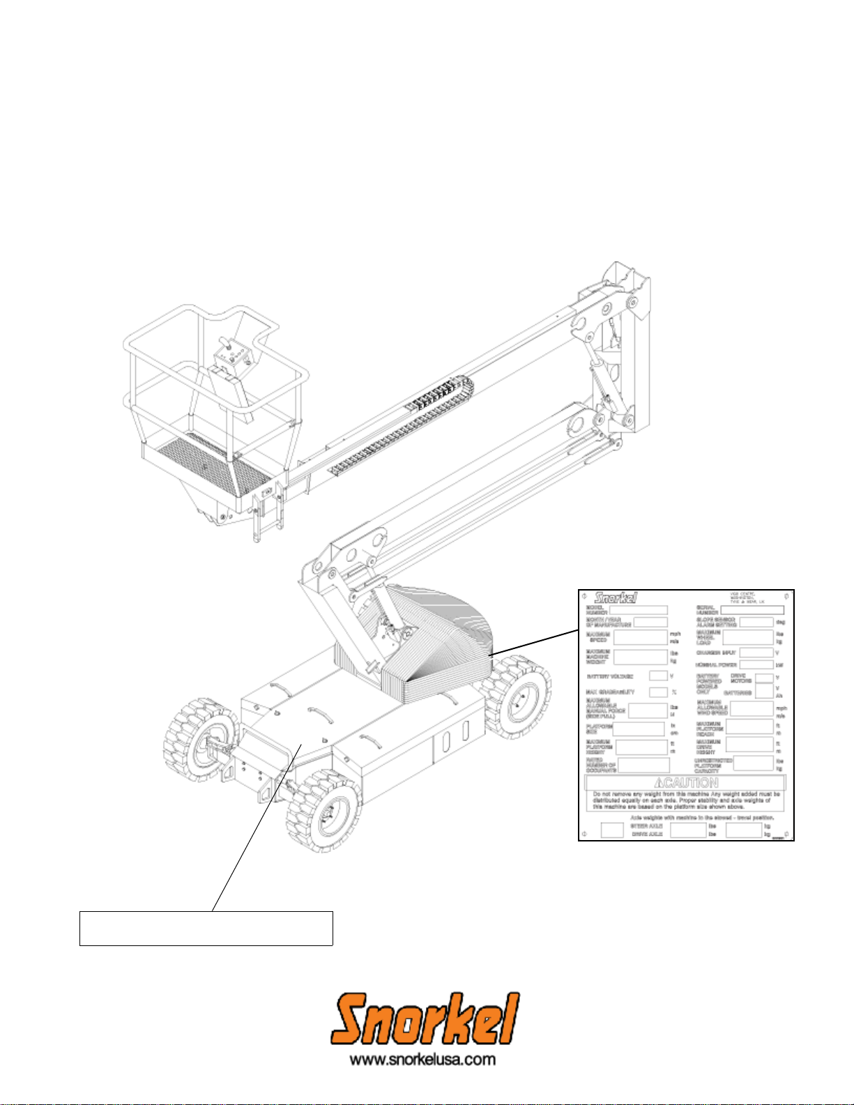
When contacting Snorkel for service or parts information, be sure to include the MODEL and SERIAL NUMBERS from the
equipment nameplate. Should the namepla te be missing, the SERIAL NUMBER is also stamped on top of the chassis
above the front axle pivot.
Serial number stamped on floor of chassis
beneath the steering cylinder.
Nameplate location
www.upright.com
Page 4

Page 5
OPERATION MANUAL
C
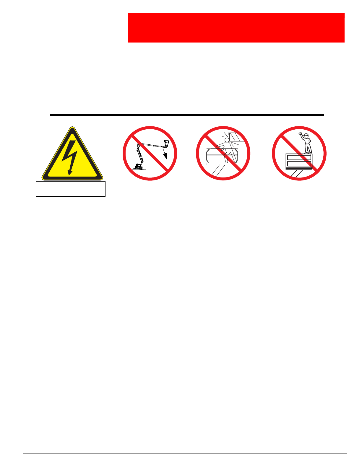
WARNING
All personnel shall carefu ll y read, under stand and f ollow a ll saf ety rules and operating inst ructions
before operating or performing maintenance on any Snorkel aerial work platform.
Safety Rules
Electrocution Hazard Tip Over Hazard
UpRightAB38
THIS MACHINE IS NOT
INSULATED!
USE OF THE AERIAL WORK PLATFORM: This aerial work platform is intended to lift persons and his tools as well as the material used
for the job. It is designed for repair and assembly jobs and assignments at overhead workplaces (ceilings, cranes, roof structures, buildings etc.). All other uses of the aerial work platform are prohibited!
THIS AERIAL WORK PLATFORM IS NOT INSULATED! For this reason it is imperative to keep a safe distance from live parts of electrical equipment!
Exceeding the specified permissible maximum load is prohibited! See “Platform Capacity” on page 4 for details.
The use and operation of the aerial work platform as a lifting tool or a crane is prohibited!
NEVER exceed the manual force allowed for this machine. See “Manual Force” on page 4 for details.
DISTRIBUTE all platform loads evenly on the platform.
NEVER operate the machine without first surveying the work area for surface hazards such as holes, drop-offs, bumps, curbs, or debris;
and avoiding them.
OPERATE machine only on surfaces capable of supporting wheel loads.
NEVER operate the machine when wind speeds exceed this machine’s wind rating. See “Beaufort Scale” on page 4 for details.
IN CASE OF EMERGENCY push EMERGENCY STOP switch to deactivate all powered functions.
IF ALARM SOUNDS while platform is elevated, STOP, carefully lower platform. Move machine to a firm, level surface.
Climbing up the railing of the platform, standing on or stepping from the platform onto buildings, steel or prefab concrete structures, etc.,
is prohibited!
Dismantling the entry gate or other railing components is prohibited! Always make certain that the entry gate is closed and securely
locked!
It is prohibited to keep the entry gate in an open position when the platform is raised!
To extend the height or the range by placing of ladders, scaffolds or similar devices on the platform is prohibited!
NEVER perform service on machine while platform is elevated without blocking elevating assembly.
INSPECT the machine thoroughly for cracked welds, loose or missing hardware, hydraulic leaks, loose wire conne ctions, and damaged
cables or hoses before using.
VERIFY that all labels are in place and legible before using.
NEVER use a machine that is damaged, not functioning properly, or has damaged or missing labels.
To bypass any safety equipment is prohibited and presents a danger for the persons on the aerial work platform and in its working range.
NEVER charge batteries near sparks or open flame. Charging batteries emit explosive hydrogen gas.
Modifications to the aerial work platform are prohibited or permissible only at the approval by Snorkel.
AFTER USE, secure the work platform from unauthorized use by turning the keyswitch off and removing key.
The driving of MEWP’s on the public highway is subject to regulations made under the Road Traffic Acts.
NEVER elevate the platf orm or drive
the machine while elevated unless
the machine is on a firm, level
surface.
ollision Hazard Fall Hazard
NEVER position the platform
without first checking for overhead
obstructions or other hazards.
NEVER climb, stand, or sit on
platform guardrails or midrail.
Operation Manual Page 1
Page 6

C
ONTENTS
Safety Rules. . . . . . . . . . . . . . . . . . . . . . . . . . . . . . . . . . . . . . . . . . . . . . . . . . . . . . . . . . . . . . . . . . . . Page 1
Introduction & General Description. . . . . . . . . . . . . . . . . . . . . . . . . . . . . . . . . . . . . . . . . . . . . . . . . Page 3
Special Limitations . . . . . . . . . . . . . . . . . . . . . . . . . . . . . . . . . . . . . . . . . . . . . . . . . . . . . . . . . . . . . . Page 4
Controls & Indicators . . . . . . . . . . . . . . . . . . . . . . . . . . . . . . . . . . . . . . . . . . . . . . . . . . . . . . . . . . . . Page 5
Pre-Operation & Safety Inspection . . . . . . . . . . . . . . . . . . . . . . . . . . . . . . . . . . . . . . . . . . . . . . . . . Page 5
System Functions . . . . . . . . . . . . . . . . . . . . . . . . . . . . . . . . . . . . . . . . . . . . . . . . . . . . . . . . . . . . . . . Page 6
Operation . . . . . . . . . . . . . . . . . . . . . . . . . . . . . . . . . . . . . . . . . . . . . . . . . . . . . . . . . . . . . . . . . . . . . . Page 6
Emergency Lowering . . . . . . . . . . . . . . . . . . . . . . . . . . . . . . . . . . . . . . . . . . . . . . . . . . . . . . . . . . . . Page 7
Transporting the Machine . . . . . . . . . . . . . . . . . . . . . . . . . . . . . . . . . . . . . . . . . . . . . . . . . . . . . . . . Page 8
Hour Meter . . . . . . . . . . . . . . . . . . . . . . . . . . . . . . . . . . . . . . . . . . . . . . . . . . . . . . . . . . . . . . . . . . . . . Page 8
Maintenance. . . . . . . . . . . . . . . . . . . . . . . . . . . . . . . . . . . . . . . . . . . . . . . . . . . . . . . . . . . . . . . . . . . . Page 9
Battery Maintenance . . . . . . . . . . . . . . . . . . . . . . . . . . . . . . . . . . . . . . . . . . . . . . . . . . . . . . . . . . . . Page 10
Inspection & Maintenance Schedule. . . . . . . . . . . . . . . . . . . . . . . . . . . . . . . . . . . . . . . . . . . . . . . Page 11
Daily Preventative Maintenance Checklist . . . . . . . . . . . . . . . . . . . . . . . . . . . . . . . . . . . . . . . . . . Page 12
Decal Location. . . . . . . . . . . . . . . . . . . . . . . . . . . . . . . . . . . . . . . . . . . . . . . . . . . . . . . . . . . . . . . . . Page 13
Specifications . . . . . . . . . . . . . . . . . . . . . . . . . . . . . . . . . . . . . . . . . . . . . . . . . . . . . . . . . . . . . . . . . Page 14
Page 2 Operation Manual
Page 7
I
NTRODUCTION
G
ENERAL
Introduction
This manual covers the AB38N and the AB38W Aerial Work Platforms.
This manual must be stored on the machine at all times.
Read, understand and follow all safety rules and operating instructions before attempting to operate the
machine.
D
ESCRIPTION
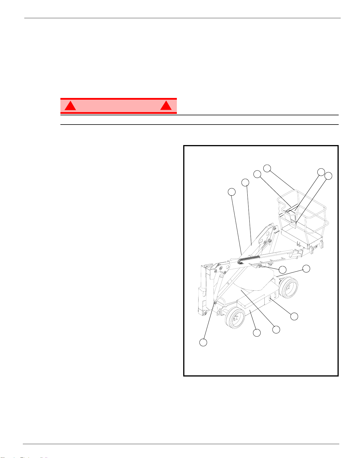
!
WARNING
DO NOT use the maintenance platform without guard rails properly assembled and in place.
1. Platform
2. Entry Bar
3. Elevating Assembly
4. Platform Controls
5. Manual Case
6. Lower Controls
7. Hydraulic Reservoir
8. Level Sensor
9. Batteries
10. Emergency Lowering Valves
11. Battery Charger
!
1
2
3
6
10
Figure 1: AB38
4
5
8
11
9
10
Operation Manual Page 3
7
Page 8
Special Limitations
S
PECIAL
The elev ating function shall ONLY be used when the work platform is level and on a firm surface.
The work platform is NOT intended to be driven over uneven, rough, or soft terrain.
P
LATFORM
DO NOT exceed the maximum platform capacity or the platform occupancy limits for this machine.
M
L
IMITATIONS
Travel with the platform raised is limited to creep speed range.
Elevating the platform is limited to firm, level surfaces only.
DANGER
! !
C
APACITY
Two people and tools may occupy the platform. The maximum platform capacity for the AB38N/W is
stated in the ‘Specifications’ on page 14.
DANGER
! !
ANUAL
Manual force is t he force applied by the occupants to objects such as wa lls or o ther structures out side the
work platform.
F
ORCE
The maximum allowable manual force is limited to 200 N (45 lbs.) of force per occupant, with a maximum
of 400 N (90 lbs.) for two occupants.
DANGER
! !
DO NOT exceed the maximum amount of manual force for this machine.
L
IFT
O
VERLOAD
The AB38 is fitted with a load sensing system designed to comply with the requirements os BS EN 280:
2001
If a load equivalent to 90% of safe working load is lifted a fault code “03” will be displayed on the digital
display on the platform control box. If a load which is greater than the safe working load is present in the
basket all machine functions will cease to operate and an acoustic warning will sound. In order to return to
normal operation a load equal to or less than the saf e w orking load must be present in the bask e t and the
power must be re-cycled, power can be re-cycled by pushing the emergency stop button and releasing it
again.
B
EAUFORT SCALE
Never op erate the machine when wind speeds excee d 12.5 m/s (28mph) [Beaufort scale 6].
BEAUFORT
RATING
3 3,4~5,4 12,25~19,4 11.5~17.75 7.5~12.0 Papers and thin branches move, flags wave.
4 5,4~8,0 19,4~28,8 17.75~26.25 12.0~18 Dust is raised, paper whirls up, and small branches sway.
5 8,0~10,8 28,8~38,9 26.25~35.5 18~24.25 Shrubs with leaves start swaying. Wave crests are apparent in ponds or swamps.
6 10,8~13,9 38,9~50,0 35.5~45.5 24.5~31 Tree branches move. Power lines whistle. It is difficult to open an umbrella.
7 13,9~17,2 50,0~61,9 45.5~56.5 31.~38.5 Whole trees sway. It is difficult to walk against the wind.
m/s km/h ft/s mph
WIND SPEED
A
LARM
GROUND CONDITIONS
Page 4 Operation Manual
Page 9
C
ONTROLS
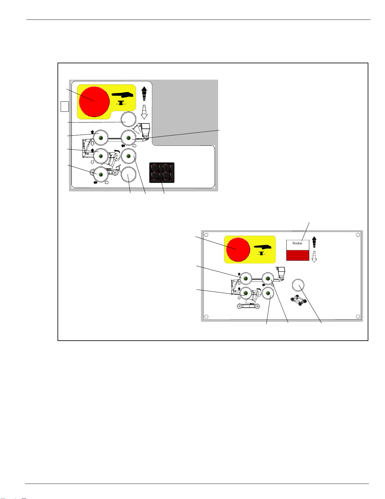
Controls and Indicators
AND
The operator shall know the location of each control and indicator and have a thorough knowledge of the
function and operation of each before attempting to operate the unit.
Upper Controls
I
NDICATORS
Figure 2: Controls and Indicators
1. Emergency Stop
1
11
2
3
4
5
6
7
1. Emergency Stop
2. Upper Boom
3. Lower Boom
2. Cage Level
3. Upper Boom
4. Lower Boom
10
5. Drive
9
6. Horn
7. Slew (Rotate)
8. Display
9. Telescope
10. Joystick
11. Key Switch (on side of box)
8
Lower Controls
7
1
2
P
RE
4. Slew (Rotate)
5. Telescope
6. Enable
7. Analog Rocker
-O
PERATION
NOTE: Carefully read, understand and follow all safety rules, operating instructions, labels and National Safety
Instructions/Requirements. Perform the following steps each day before use.
1. Remove the Chassis Covers and inspect f or damage, fluid leaks or missing parts.
2. Check the level of the hydraulic fluid with the platform fully lowered. Remove the Chassis Covers and
remove the reservoir cap, fluid should be visible on the dipstick. Add recommended hydraulic fluid if
necessary. See “Specifications” on page 14.
3. Check that the fluid level in the batteries is correct. See “Battery Maintenance” on page 10.
4. Verify that the batteries are charged.
5. Check that the A.C. extension cord has been disconnected from the chassis outlet.
6. Check that all guardrails are in place and all fasteners are properly tightened.
7. Inspect the machine thoroughly for cracked welds and structural damage, loose or missing hardware,
hydraulic leaks, damaged control cable and loose wire connections.
S
AFETY
I
3
NSPECTION
4
5
6
Operation Manual Page 5
Page 10

System Function Inspection
S
YSTEM
F
UNCTION
Refer to Figure 1 and Figure 2 for the locations of various controls and indicators.
I
NSPECTION
!
WARNING
STAND CLEAR of the work platform while performing the following checks.
Before operating the machine, survey the work area for surface hazards such as holes, drop-offs, bumps
and debris.
Check in ALL directions, including above the work platform, for obstructions and electrical cond u cto rs.
Protect the control console cable from possible damage while performing checks.
1. Move the machine, if necessary, to an unobstructed area to allow for full elevation.
2. Pull Chassis Emergency Stop Switch to the ON position.
3. Pull Platform Emergency Stop Switch to the ON position.
4. Visually inspect the elevating assembly , lif t cylinder, cables, and hoses for crac ked welds and structural
damage, loose hardware, hydraulic leaks, loose wire connections, and erratic operation. Check for
missing or loose par ts.
5. Test each machine function (Lift, Slew, Telescope) from the lower control station by pressing and
holding the desired function button then moving the Analog Rocker to the Up or Down position (ref:
chassis controls illustration on page 5)
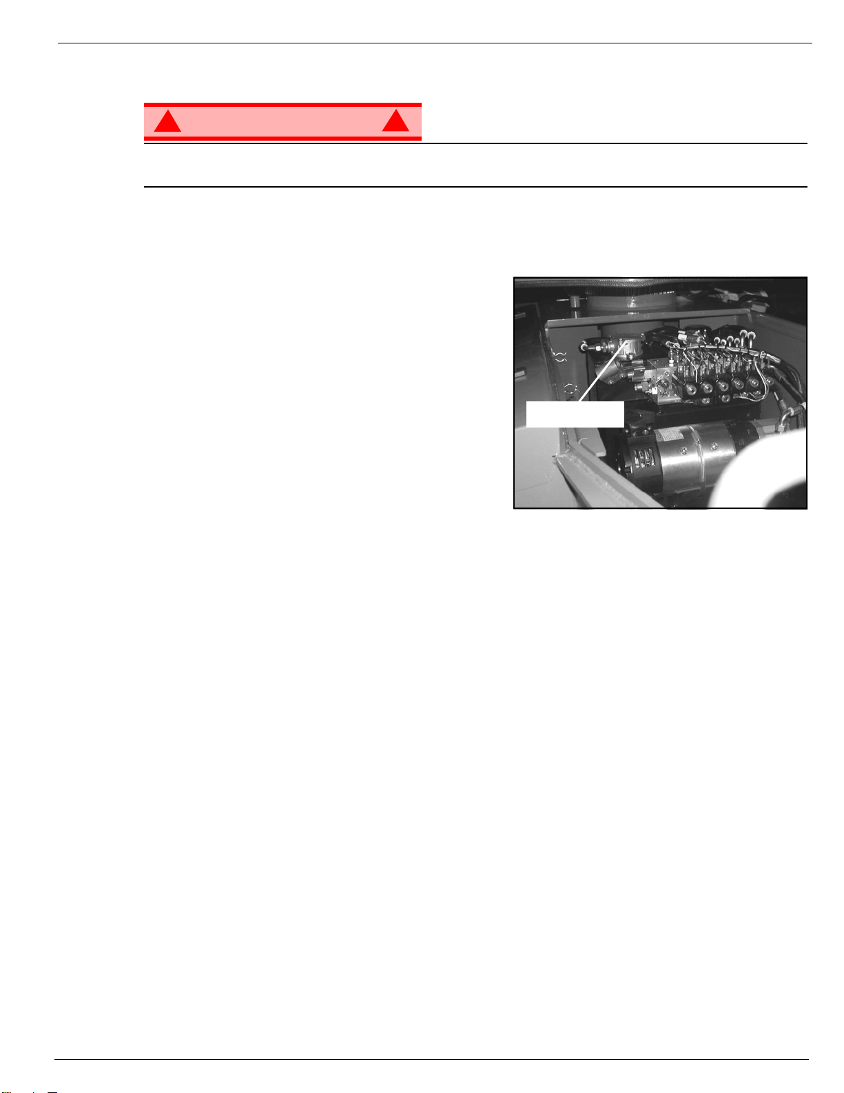
6. Open the Emergency Lowering Valve (see Figure 3) by pulling the knob out to check for proper
operation. When the platform is lowered, release the knob.
7. Push the Chassis Emergency Stop Switch to check for proper operation. All machine functions should
be disabled. Twist the Chassis Emergency Stop Switch to resume.
8. Climb onto the cage.
9. Check that the route is clear of obstacles (persons, obstructions, debris), is level, and is capable of
supporting the wheel loads.
10. Mount the platform and properly close the drop bar.
11. Test each machine function (Drive, Lift, Slew, Telescope, Platform Rotate, Cage Level) from the upper
control station by pressing the desired fun ct ion button then moving the Joystick to the Forward or Back
position (ref: platform controls illustration on page 5)
12. Push the Platform Emergency Stop Switch to check for proper oper ation. All machine functions should
be disabled. Pull out the Platform Emergency Stop Switch to resume.
!
O
PERATION
Before operating t he wo rk platform, ensure that the Pre- Oper atio n Safety Inspection has been completed
and that any deficiencies ha v e been cor rected. Ne ver opera te a dama ged or malfunctioning mac hine.
The operator must be thoroughly tr ained on this machine.
E
LEVATING
1. Select either the lower or upper boom lift function button (the button will illuminate to confirm selection).
2. While engaging the Interlock Switch, push the Control Handle forward.
3. If the machine is not level the tilt alarm will sound and the machine will not lift.
L
OWERING
1. Select either the lower or upper boom lift function button (the button will illuminate to confirm selection).
2. While engaging the Interlock Switch, pull the Control Handle backwards.
3. If the machine is not level the tilt alarm will sound and the machine will only descend.
Page 6 Operation Manual
THE
THE
P
P
LATFORM
LATFORM
Page 11
Operation
R
OTATING
1. Select the rotate function button (the button will illuminate to confirm selection).
2. While engaging the Interlock Switch, move the Control Handle forwards or backwards to achieve
clockwise or counter clockwise rotation.
3. If the machine is not level the tilt alarm will sound and the machine will not rotate.
O
PERATING
1. Select telescope function button (the button will illuminate to confirm selection).
2. While engaging the Interlock Switch, move the Control Handle forwards or backwards to exten d or
retract the telescopic boom.
3. If the machine is not level the tilt alarm will sound and the telescope boom will only retract.
NOTE: The AB38W is equipped with a safety system preventing any drive motion when the machine is out of the stow
position and with the telescope extended beyond a pre-set limit.
L
EVELLING
1. Select platform level function button (the button will illuminate to confirm selection).
2. While engaging the Interlock Switch , m ove the Control Handle forwards or backwards to adjust the floor
angle of the cage (this can only be done when the machine is in the stowed position).
3. If the machine is not level the tilt alarm will sound and the machine will not operate.
THE
P
THE
THE CAGE
LATFORM
T
ELESCOPE
E
MERGENCY
!
WARNING
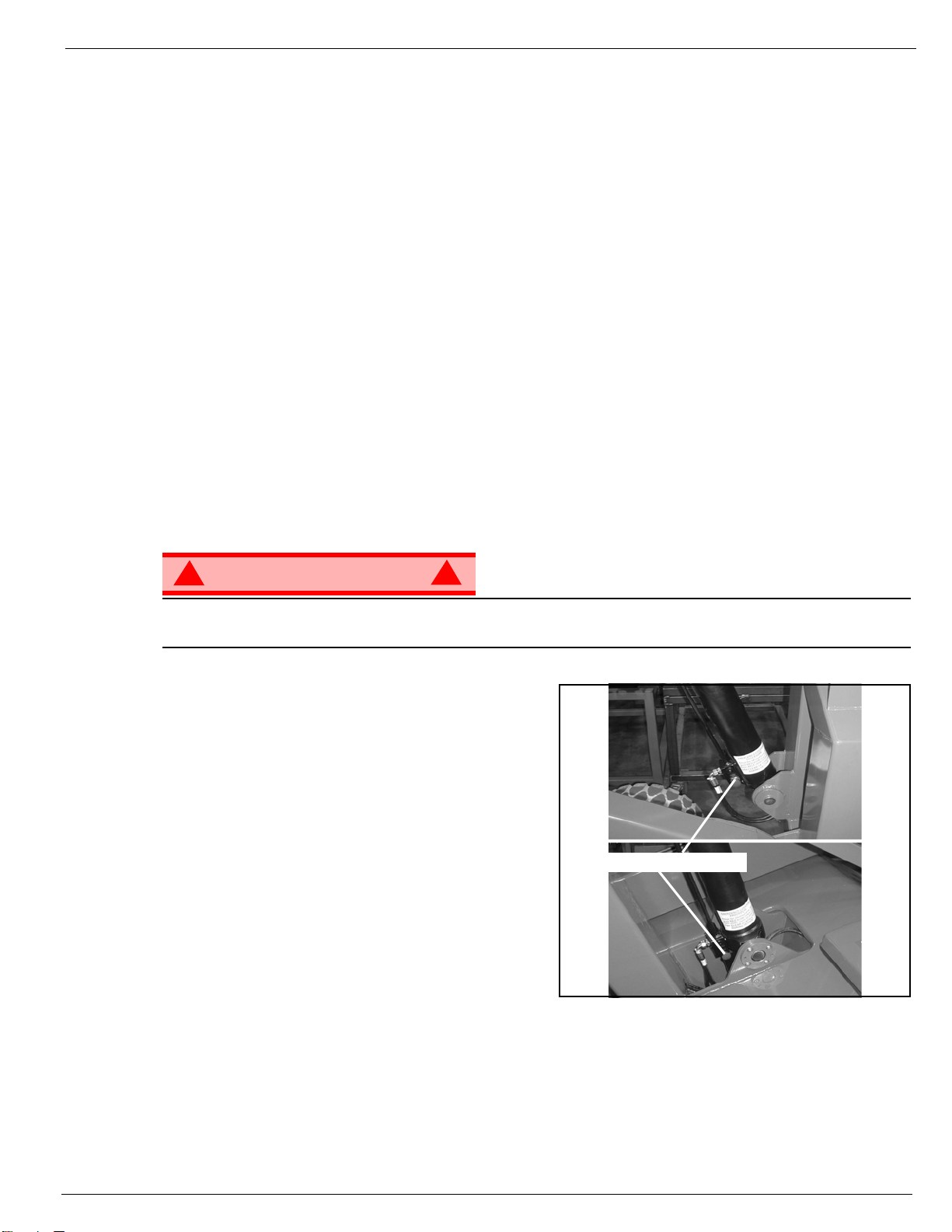
If the platform should fail to lower, NEVER climb down the elevating assembly.
Stand clear of the elevating assembly while operating t he Emergency Lowering Valve Knob.
Ask a person on the ground to open the Emergency
Lowering V alve to lower the platf orm. The Emergency
Lowering Valve is located on the base of each lift
cylinder.
1. Open the Emergency Lowering V alve b y pulling the
knob out.
2. To close, release the knob .
NOTE: The platform will not elevate if the Emergency
Lowering Valve is open.
L
OWERING
!
Figure 3: Emergency Lowering Valve
Emergency Lowering Valves
A
FTER
1. Ensure that the platform is fully lowered.
2. Park the machine on a firm level surface, preferably under cover, secure against vandals, children and
3. Turn the Chassis Key Switch to OFF and remove the key to prevent unauthorized operation.
Operation Manual Page 7
U
SE
E
ACH
unauthorized operation.
D
AY
Page 12
Transporting the Machine
T
RANSPORTING
THE
M
ACHINE
BY C
BY F
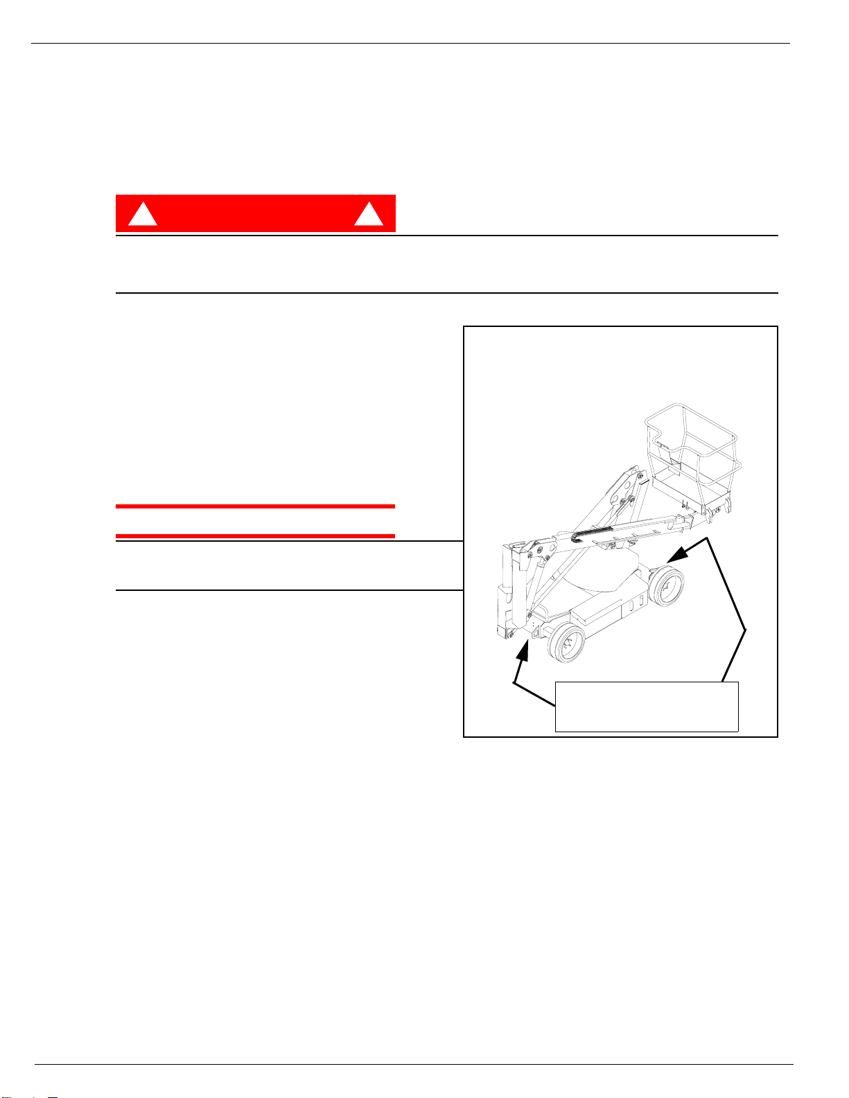
Forklifting and Lifting by Crane are for transport only.
See specifications for weight of machine and be certain that forklift is of adequate capacity to lift the
machine.
BY T
1. Maneuver th e machine into tr ansport position and
2. Secure the machine to the transport vehicle with
RANE
Secure the straps to chassis lifting/tie down points only.
ORKLIFT
DANGER
! !
Forklift from the side by lifting under the Chassis.
RUCK
chock wheels.
chains or straps of adequate load capacity
attached to the chassis lifting/tie down points.
Figure 4: Transporting the Machine
CAUTION
Over tightening of the chains or straps attached to
the Tie Down lugs may result in damage to the
machine
H
OUR
To access the hour meter func tio n perfor m the following steps.
1. Climb into the basket (with the machine powered up)
2. Push the platform emergency stop button.
3. Hold down the following buttons, Horn, Telescope & Upper Boom Lift.
M
ETER
Lift / Tie Down Points
4. While holding the buttons twist the emergency stop button to return power to the machine.
5. “hr” will now be displayed on the read-out, Pressing the right turn button will scroll through the
accumulated hours two digits at a time. For example, if pressing the right turn button once displays “20”,
pressing it a 2nd time displays “58”, and pres sing it a 3rd tim e displays “hr”, the elapsed time of operation
is 2058 hours.
Page 8 Operation Manual
Page 13
M
AINTENANCE
Maintenance
!
WARNING
Never perform service while the platform is elevated.
H
YDRAULIC
The hydraulic fluid reservoir is located in the chassis door.
NOTE: Never add fluid if the platform is elevated.
C
HECK HYDRAULIC FLUID
1. Make sure that the platform is fully lowered.
2. Open the chassis door.
3. Remove the filler cap from the hydraulic fluid
reservoir.
4. Check the fluid level on the dipstick on the filler cap.
5. Add the appropriate fluid to bring the le vel to the FULL
mark. See “Specifications” on page 14
F
LUID
!
Figure 5: Hydraulic Fluid Reservoir and Dipstick
Filler Cap
Operation Manual Page 9
Page 14
Maintenance
B
ATTERY
M
AINTENANCE
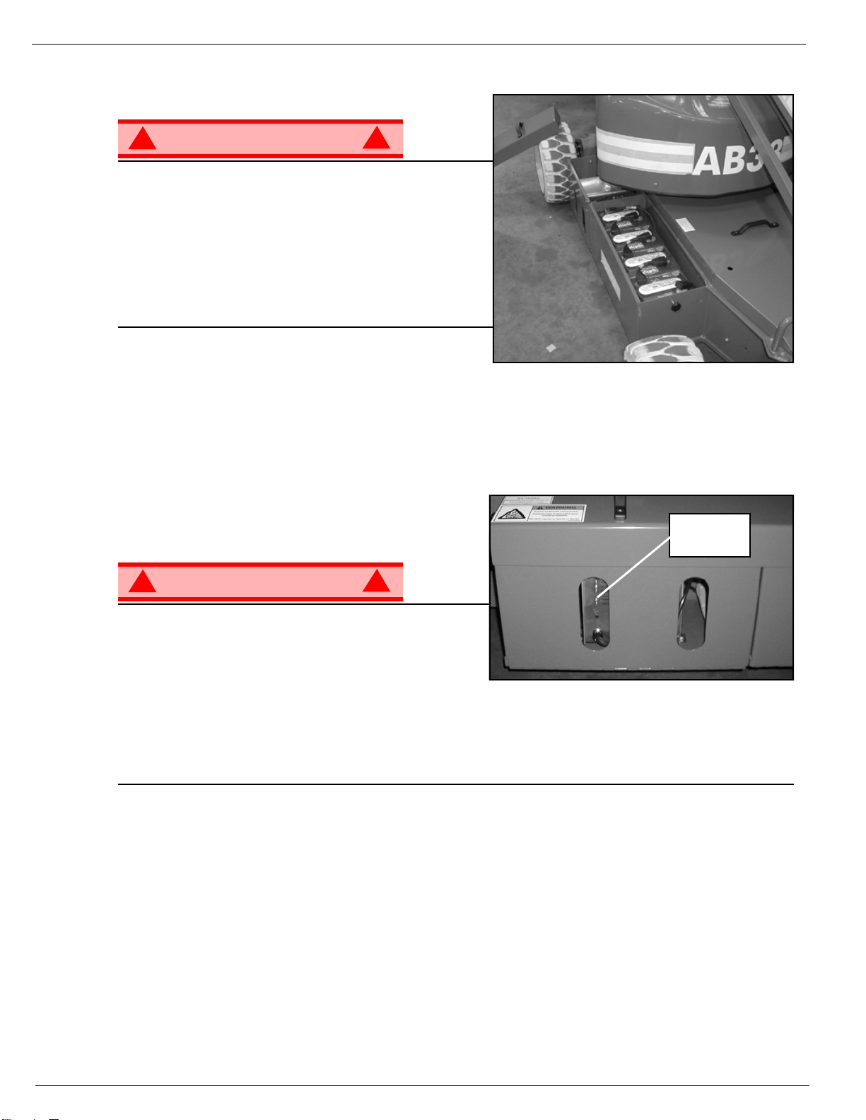
Figure 6: Access to Batteries
!
WARNING
Hazard of explosive gas mixture. Keep sparks, flame,
and smoking material away from batteries.
Always wear safety glasses when working near
batteries.
Battery fluid is highly corrosive. Thoroughly rinse away
any spilled fluid with clean water.
Always replace batteries with Snorkel batteries or
manufacturer approved replacements weighing 26,3 kg
(58 lbs.) each.
• Check the battery fluid level daily, especially if the
machine is being used in a warm, dry climate.
• If electrolyte level is lower than 10 mm
tap water with high mineral content, as it will shorten battery life.
• Keep the terminals and tops of the batteries clean.
• Refer to the Service Manual to extend battery life and for complete service instructions.
B
ATTERY CHARGING
Charge the batteries at the end of each work shift or
sooner if the batteries have bee n discharged.
!
3
(
/
in.) above the plates add distilled water only. DO NOT use
8
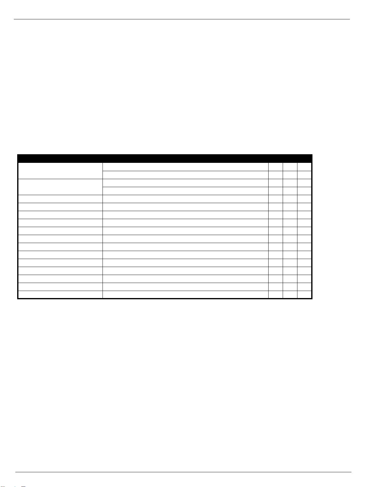
Figure 7: Battery Charge Indicator
Battery
Charge
Indicator
!
WARNING
Charge the batteries in a well ventilated area.
Do not charge the batteries when the machine is near a
source of sparks or flames.
Permanent damage to the batteries will result if the
batteries are not immediately recharged after
discharging.
Never leave the battery charger operating for more than two days.
Never disconn ect the cables from the batteries when the charger is operating.
Keep the charger dry.
1. Check the battery fluid level. If the battery fluid level is lower than 10 mm
distilled water only.
2. Connect an appropriate exte nsion co rd t o charg er outlet plug in Right Module Door. Plug the extension
cord into a properly grounded outlet of proper voltage and frequency .
3. The charger turns on automatically after a short delay. The LED charge indicator will illuminate. After
completion of the charge cycle the LED will blink, indicating that the charger is in a continuing
maintenance mode. DO NOT leave the charger plugged in for more than 48 hours, as permanent
damage to the batteries may occur.
NOTE: The battery charger circuit must be used with a GFI (Ground Fault Interrupt) outlet.
!
3
(
/
in.) above the plates add
8
NOTE: DO NOT operate the machine while the charger is plugged in.
Page 10 Operation Manual
Page 15

I
NSPECTION
Inspection and Maintenance Schedule
AND
The Complete Inspection consists of periodic visual and operational checks, along with periodic minor
adjustments that assure proper performance. Daily inspection will prevent abnormal wear and prolong the
life of all systems. The inspection and maintenance schedule should be performed at the specified
intervals. Inspection and maintenance shall be performed by personnel who are trained and familiar with
mechanical and electric al pr ocedures.
M
AINTENANCE
S
CHEDULE
!
WARNING
Before performing preventative maintenance, familiarize yourself with the operation of the machine.
Always block the elevating assembly whenever it is nece ssary to perform maintenance while t he
platform is elevated.
The daily preventative maintenance checklist has been designed for machine service and maintenance.
Please photocopy the Daily Pre v en tativ e Maintenance Chec klist and use t he chec klist when inspecting the
machine.
!
Operation Manual Page 11
Page 16
Daily Preventative Maintenance Checklist
D
AILY
M
AINTENANCE
P
REVENTATIVE
T
ABLE KEY
M
AINTENANCE
C
HECKLIST
P
REVENTATIVE MAINTENANCE
R
EPORT
Y = Yes/Acceptable
N = No/Not Acceptable
R = Repaired/Acceptable
___________________________________________
COMPONENT INSPECTION OR SERVICES Y N R
Battery
Chassis
Control Cable Check the exterior of the cable for pinching, binding or wear.
Controller Check switch operation.
Drive Motors Check for operation and leaks.
Elevating Assembly Inspect for structural cracks.
Emergency Hydraulic System Operate the emergency lowering valve and check for serviceability.
Entire Unit Check for and repair collision damage.
Hydraulic Fluid Check fluid level.
Hydraulic Pump Check for hose fitting leaks.
Hydraulic System Check for leaks.
Labels Check for peeling, missing, or unreadable labels & replace.
Platform Deck and Rails Check welds for cracks.
Platform Deck and Rails Check condition of deck.
Tires Check for damage.
Check electrolyte level.
Check battery cable condition.
Check hoses for pinch or rubbing points.
Check welds for cracks.
Date: _______________________________________
Owner:______________________________________
Model No: ___________________________________
Serial No:____________________________________
Serviced By:
Page 12 Operation Manual
Page 17

D
ECAL
L
OCATION
Decal Location
ITEM PART NO. DESCRIPTION QTY.
1 500264-000 DECAL - Snorkel AB38 BOOM 2
2 501870-000 DECAL - LOWER CONTROL BOX 1
3 500257-001 DECAL - AB38 LOGO 1
4 057695-000 DECAL - BALLAST STRIP 1
5 502480-000 DECAL - EMERGENCY LOWERING 2
6 057696-000 DECAL - ‘Snorkel’ LOGO 2
7 057429-000 DECAL - BATTERY FLUID LEVEL 2
8 057430-000 DECAL - EXPLOSION HAZARD 2
12 058881-001 DECAL - HAZARD TAPE 2
13 058080-000 DECAL - CAGE LEVELLING 1
14 058186-000 DECAL - ON/OFF UPPER CONTROL 1
16 501869-000 DECAL - UPPER CONTROL BOX 1
17 058538-000 DECAL - DANGER/HAZARDS/INSTR. 1
18 058530-000 DECAL - MEETS ANSI REQUIREMENTS 1
19 058534-000 DECAL - BATTERIES ARE 2
20 058533-000 DECAL - DO NOT ADJUST SWITCHES 2
21 058761-000 DECAL - S.W .L. LARGE ANSI 1
22 057434-000 DECAL - GENUINE REPLACEMENTS 2
23 057424-001 DECAL - CRUSH HAZARD 4
24 058535-000 DECAL - CAUTION BEFORE 1
25 058536-000 DECAL - IMPACT FROM DESCENDING 1
26 058531-000 DECAL - TIE DOWN / LIFT POINT 4
27 500438-000 DECAL - LOWER CONTROL BOX 1
28 058539-000 DECAL - ALL PERSONNEL SHALL BE 1
29 058537-000 DECAL - PINCH POINT 2
30 058471-001 NAME PLATE - ANSI 1
31 058532-000 DECAL - HYDRAULIC FLUID 1
32 500424-000 ANSI OPERATORS MANUAL 1
33 500422-001 SERVICE & PARTS MANUAL 1
34 057425-001 DECAL - INSTRUCTIONS INSIDE 1
35 058761-000 DECAL - SW L 475lb 1
Operation Manual Page 13
Page 18

Specifications
S
PECIFICATIONS
Duty Cycle 45% of 8 hour shift 45% of 8 hour shift
Platform Size 0.7 m x 1.3 m (inside guardrails) 2.3ft x 4.3 ft (inside gaurdrails)
Max. Platform Capacity
CE Ver sion 200kg (W) or 215kg (N) 441lbs(W) or 475lbs (N)
ANSI Version 215 kg 475 lbs
Max. Number of Occupants 2 People 2 People
Height
Max imum Working Height
Max imum Platform Height 11 .45 m 37.5 6 ft
Min. Platf orm Floor Height 0 .65 m 2.1 3 ft
Max. Working Outreach 6.10 m 20.00 ft
Platform Height at
Maximum Outreach 5.40 m 17.72 ft
Stowed Dimensions
Length 4.04 m 13.25 ft
Width 1.72m (W) or 1.5m (N) 5.61ft (W) or 4.92 ft (N)
Height 2.0 0 m 6.5 6 ft
Ground Clearence 0.13 m 0.43 ft
Wheel Base X Guage 2.00m x 1.49m (W) or 1.27m (N) 6.56 ft (W) x 4.16 ft (N)
Rotation 362 degrees non-continuous 362 degrees non-continuous
Gros s Weight-CE Version 3200kg (W) or 3800kg (N) 7055lbs (W) or 8378lbs (N)
Gros s Weight-ANSI Version 3400kg (W) or 4108kg (N) 7496lbs (W) or 9057lbs (N)
Drive Speed Stowed 0 - 4 km/h 0 - 2.49 mph
Drive Speed Elevated 0 - 0.72 km/h 0 - 0.45 m ph
Maximum Gradeability 36% 36%
Inside Turning Radius 0.40 m 1.31 ft
Outside Turning Radius 2.66 m (W) or 2.4 m (N) 8.72ft (W) or 7.87ft (N)
Power Source 48V DC 4kw, 8 x 6V 220Ah Batteries 48V DC 5.4 HP, 8 x 6V 220Ah Batteries
System Voltage 48V 48V
Battery Charger 48V 25A 220/110VAC 50/60 Hz 48V 25A 220/110VAC 50/60 Hz
Hydraulic Tank Capacity 25 Litres 6.5 Gallons US
Max. Hydraulic Pressure 175 bar 2540 psi
Hydraulic Oil ISO #46 ISO #46
Li ft Syste m 2 Double a ctin g lift cylinders wi th 2 Double acting lift cylinders with
Lock Valves and Manual Em ergency Lock Valves and Manual Emergency
Control System One handed Proportional Joystick One handed Proportional Joystick
Wheels/Tires 400 mm Diameter Steel Disc Wheel 15.75 inch Diameter Steel Disc Wheel
Braking Automatic Spring Applied Automatic Spring Applied
Sound Pressure Level at 70 db(A) 70 db(A)
Table 1-1 : Specifications
ITEM METRIC IMPERIAL
13 .45 m 44.1 2 ft
Lowering Facility. Lowering Facility.
1 Double Acting Telescopic Cylinder 1 Double Acting Telescopic Cylinder
Ope rati ng Energy Efficient Motor Operatin g En ergy Effici ent Mo tor
Control System Control System
with Solid all Surface tires with Solid all Surface tires
Hydraulic Release Hydraulic Release
Page 14 Operation Manual
Page 19

AB38
Numéros de série 3700 – actuel
FRANÇAIS
En cas de contact avec Snorkel pour obtenir des renseignements sur les réparations ou les pièces, indiquer les
NUMÉROS de MODÈLE et de SÉRIE figurant sur la plaque signalétique de la machine. En cas d'absence de plaque
signalétique, le NUMÉRO DE SÉRIE est également estampé sur le dessus du châssis, au-dessus du pivot d'essieu avant.
Le numéro de série a embouti sur le
plancher du châssis sous le vérin
d'orientation de train avant.
La plaque signalétique de la machine
www.upright.com
Page 20

Page 21

GUIDE DE L'OPÉRATEUR
AVER TISSEMENT
Tout le personnel devra lire soigneusement, comprendre et respecter tou tes le s r ègles de s écu rité
et instructions d'utilisation avant d'utiliser ou d'effectuer des travaux de maintenance sur une
Règles de sécurité
Risque d'électrocution Risque de basculement Risque de collision Risque de chute
plate-forme de travail aérien Snorkel.
UpRightAB38
CETTE MACHINE N'EST PAS
UTILISATION DE LA PLATE-FORME DE TRAVAIL AÉRIEN : Cette plate-forme est destinée à lever le personnel et ses outils ainsi que les
matériaux utilisés pour effectuer le travail. Elle est conçue pour les travaux de réparation et de montage situés en hauteur (plafonds, grues,
toitures, bâtiments, etc.). Toute autre utilisation de cette pl ate-forme de travail aérien est interdite !
CETTE PLA TE-FORME DE TRAVAIL AÉRIEN N'EST PAS ISOLÉE ! Pour cette raison, il est impératif de maintenir une distance de sécurité
entre la plate-forme et les parties sous tension de l'équipement électrique !
Tout dépassement de la charge maximum admissible spécifiée est interdit ! Voir “Capacité de la plate-forme” page 4 pour plus de détails.
L'utilisation de la plate-forme de travail aérien comme outil de levage ou comme grue est interdite !
NE JAMAIS dépasser la force manuelle autorisée pour cette machine. Voir “Force manuelle” page 4 pour plus de détails.
RÉPARTIR de façon égale toutes les charges sur la plate-forme.
NE JAMAIS utiliser la machine sans av oir aupar a v ant vérifié sur la surf ace de tra v ai l l'absence d e trous, déniv ell ations , bosses , trotto irs ou débris
afin de les éviter.
UTILISER la machine uniquement sur des surfaces capables de supporter les charges par roue.
NE JAMAIS utiliser la machine quand la vitesse du v ent dépasse la résistance nominale au vent de la machine. Voir “Beaufort Scale” on page 4
pour plus de détails.
EN CAS D'URGENCE, appuyer sur le bouton d'ARRÊT D'URGENCE pour désactiver toutes les fonctions en action.
SI L'ALARME RETENTIT pendant que la plate-forme est en position haute, ARRÊTER la p late-forme et la descendre a vec précaution. Déplacer
la machine sur une surface ferme et de niveau.
Escalader le garde-corps de la plate-fo rme, pa sser de la plate-forme sur des constructions ou des structures en acier ou béton préfabriqué, et c.,
est interdit !
Le démontage de la porte d'entrée ou d'autres composants du garde-corps est interdit ! Toujours s'assurer que la porte d'entrée est fermée et
correctement verrouillée!
Il est interdit de maintenir la porte d'entrée en position ouverte quand la plate-forme est levée !
L'extension de la hauteur ou de la portée de la plate-f orme en y plaçant des échelles, échafaudages ou dispos itifs similaires est interdite !
NE JAMAIS effectuer de réparations sur la machine pendant que la plate-forme est levée sans bloquer l'ensemble de levage.
INSPECTER soigneusement la machine pour vérifier l'absence de soudures fissurées, pièces de fixation desserrées ou manquantes, fuites
hydrauliques, connexions de câblage desserrées et câbles ou tuyaux endommagés avant toute utilisation.
VÉRIFIER que toutes les étiquettes sont en place et lisibles avant toute utilisation.
NE JAMAIS utiliser une machine endommagée, qui ne fonctionne pas correctement ou dont les étiquettes sont endommagées ou manquantes.
La neutralisation de tout équ ipe ment d e sécurité est interdite et présente un danger pour les pe rsonne s se tenant sur la plate-forme de tr a vail et
sa zone d'activité.
NE JAMAIS charger les batteries près d'étincelles ou d'une flamme nue. La charge des batteries cause l'émission d'hydrogène explosif.
Les modifications de la plate-forme de travail aérien sont interdites ou autorisées seulement après approbation de
APRÈS UTILISATION, empêcher tout e utilisation non autorisée de la plate-forme de travail en coupant le contact et en retirant la clé.
ISOLÉE !
NE JAMAIS élever la plate-for me
ou conduire la machine avec la
plate-forme élevée sauf sur une
surface ferme et de niveau.
NE JAMAIS positionner la plate-
forme sans vérifier au préalable qu'il
n'existe pas d'obstructions ou
autres risques au-dessus.
NE JAMAIS grimper, se tenir
debout ou assis sur les
garde-corps ou la rampe
intermédiaire de la plate-forme.
Snorkel.
Guide de l'opérateur Page 1
Page 22

T
ABLE
DES MATIÈRES
Utilisation
Règles de sécurité. . . . . . . . . . . . . . . . . . . . . . . . . . . . . . . . . . . . . . . . . . . . . . . . . . . . . . . . . . . . . . . Page 1
Introduction & Description générale. . . . . . . . . . . . . . . . . . . . . . . . . . . . . . . . . . . . . . . . . . . . . . . . Page 3
Restrictions spéciales . . . . . . . . . . . . . . . . . . . . . . . . . . . . . . . . . . . . . . . . . . . . . . . . . . . . . . . . . . . Page 4
Commandes & indicateurs. . . . . . . . . . . . . . . . . . . . . . . . . . . . . . . . . . . . . . . . . . . . . . . . . . . . . . . . Page 5
Inspection de sécurité avant utilisation . . . . . . . . . . . . . . . . . . . . . . . . . . . . . . . . . . . . . . . . . . . . . Page 5
Fonctions . . . . . . . . . . . . . . . . . . . . . . . . . . . . . . . . . . . . . . . . . . . . . . . . . . . . . . . . . . . . . . . . . . . . . Page 6
Utilisation. . . . . . . . . . . . . . . . . . . . . . . . . . . . . . . . . . . . . . . . . . . . . . . . . . . . . . . . . . . . . . . . . . . . . . Page 6
Abaissement d'urgence . . . . . . . . . . . . . . . . . . . . . . . . . . . . . . . . . . . . . . . . . . . . . . . . . . . . . . . . . . Page 7
Transport de la machine. . . . . . . . . . . . . . . . . . . . . . . . . . . . . . . . . . . . . . . . . . . . . . . . . . . . . . . . . . Page 8
Horomètre . . . . . . . . . . . . . . . . . . . . . . . . . . . . . . . . . . . . . . . . . . . . . . . . . . . . . . . . . . . . . . . . . . . . . Page 8
Maintenance. . . . . . . . . . . . . . . . . . . . . . . . . . . . . . . . . . . . . . . . . . . . . . . . . . . . . . . . . . . . . . . . . . . . Page 9
Maintenance des batteries . . . . . . . . . . . . . . . . . . . . . . . . . . . . . . . . . . . . . . . . . . . . . . . . . . . . . . . Page 10
Programme d'inspection et de maintenance . . . . . . . . . . . . . . . . . . . . . . . . . . . . . . . . . . . . . . . . Page 11
Liste de vérification quotidienne de maintenance préventive . . . . . . . . . . . . . . . . . . . . . . . . . . Page 12
Étiquettes. . . . . . . . . . . . . . . . . . . . . . . . . . . . . . . . . . . . . . . . . . . . . . . . . . . . . . . . . . . . . . . . . . . . . Page 13
Spécifications . . . . . . . . . . . . . . . . . . . . . . . . . . . . . . . . . . . . . . . . . . . . . . . . . . . . . . . . . . . . . . . . . Page 14
Page 2 Guide de l'opérateur
Page 23

I
NTRODUCTION
D
ESCRIPTION
Introduction
Le présent manuel couvre la plate-forme de travail aérien AB38N/W. Il doit être rangé sur la machine
en permanence.
Il est indispensable de lire, comprendre et respecter toutes les règles de sécurité et instructions
d'utilisation avant d'essayer d'utiliser la machine.
GÉNÉRALE
Figure 1 : AB38
1. Plate-forme
!
AVERTISSEMENT
NE PAS utiliser la plate-forme de
maintenance sans les garde-corps
correctement montés et en place
2. Barre d'entrée
3. Ensemble de levage
4. Commandes de plate-forme
5. Boîte du manuel
6. Commandes inférieures
7. Réservoir hydraulique
8. Capteur de niveau
9. Batteries
10. Soupapes d'abaissement d'urgence
11. Chargeur de batterie
!
1
2
3
6
10
11
9
7
4
5
8
10
Guide de l'opérateur Page 3
Page 24

Restrictions spéciales
R
ESTRICTIONS
Tout déplacement avec la plate-forme levée est limitée à la gamme de vitesses très lentes.
L'élévation de la plate-forme est limitée uniquement aux surfaces fermes et de niveau.
! !
La fonction d'élévation sera utilisée SEULEMENT quand la plate-forme de travail est de niveau et sur une
surface ferme.
La plate-forme de travail N'EST PAS CONÇUE pour être conduite sur un terrain inégal, non nivelé
ou mou.
C
APACITÉ
Deux personnes avec leurs outils peuvent occuper la plate-forme. Voir “Spécifications” page 14
! !
NE PAS dépasser la capacité maximale de la plate-forme ni ses limites d'occupation pour cette
machine.
SPÉCIALES
DANGER
DE LA PLATE
DANGER
-
FORME
F
ORCE MANUELLE
La force manuelle est la force appliquée par les occupants aux objets tels que les murs ou autres
structures extérieures à la plate-forme de travail.
La force manuelle maximale admissible est limitée à 200 N de force par occupant, avec un maximum
de 400 N pour deux occupants.
DANGER
! !
NE PAS dépasser la valeur maximale de force manuelle pour cette machine.
A
LARME
La plate-forme AB38 est équipée d'un système de déte ction de charge conforme aux e x igences de la norme
BS EN 280 : 2001
Si une charge équivalente à 90 % d'une charge de travail de sécurité est soule vée, un code de défaut “03”
s'inscrit sur l'affichage numérique du boîtier de commande de la plate-forme. Si une charge supérieure à la
charge de travail de sécurité est présente dans la plate-forme, toutes les fonctions de la machine de viennent
inopérantes et une alarme sonore retentit. Pour revenir au fonctionnement normal, la plate-forme doit
supporter une charge inférieure ou égale à la charge de travail admissible et l'alimentation électrique doit
coupée puis rétablie en appuy an t sur le bouton d'arrêt d'urgence et en le relâchant.
DE SURCHARGE
DE LEVAGE
É
CHELLE
Ne jamais utiliser la machine quand la vitesse du vent dépasse 25 km/h [force 4 sur l'échelle de Beauf ort].
ÉCHELLE DE
BEAUFORT
3 3,4~5,4 12,25~19,4 11,5~17,75 7,5~12,0 Les papiers et branches fines bougent ; les drapeaux ondulent.
4 5,4~8,0 19,4~28,8 17,75~26,25 12,0~18 La poussière vole, les papiers tourbillonnent et les petites branches oscillent.
5 8,0~10,8 28,8~38,9 26,25~35,5 18~24,25
6 10,8~13,9 38,9~50,0 35,5~45,5 24,5~31 Les branches des arbres bougent. Les lignes électriques sifflent. Il est difficile d'ouvrir un parapluie.
7 13,9~17,2 50,0~61,9 45,5~56,5 31~38,5 Les arbres oscillent au complet. Il est difficile de marcher face au vent.
Page 4 Guide de l'opérateur
m/s km/h pi/s mi/h
VITESSE DU VENT
DE
B
EAUFORT
CONDITIONS AU SOL
Les arbustes portant des feuilles commencent à osciller. On voit les crêtes des vagues dans les
mares ou les marais.
Page 25

C
OMMANDES
Commandes et indicateurs
ET INDICATEURS
L'opérateur doit connaître l'emplacement de chaque commande et indicateur et avoir une connaissance
approfondie de la fonction et de l'utilisation de tous avant d'essayer d'utiliser la machine.
Figure 2 : Commandes et indicateurs
Commandes supérieures
1. Arrêt d'urgence
1
11
2
3
4
5
6
7
8
1. Arrêt d'urgence
2. Flèche supérieure
3. Flèche inférieure
4. Pivotement (Rotation)
5. Flèche télescopique
10
2. Niveau de la plate-forme
3. Flèche supérieure
4. Flèche inférieure
5. Déplacement
9
6. Avertisseur sonore
7. Pivotement (Rotation)
8. Affichage
9. Flèche télescopique
10. Manche à balai
11. Interrupteur à clé (sur le côté du boîtier)
Commandes inférieures
1
2
7
I
NSPECTION
6. Activation
3
7. Commutateu r à ba scu le
analogique
4
DE SÉCURITÉ
NOTE : Lire soigneusement, comprendre et respecter toutes les règles de sécurité, instructions d'utilisation, étiquettes
et instructions/exigences nationales de sécurité. Chaque jour avant utilisation, exécuter les étapes suivantes.
1. Déposer les carters de châssis et vérifier l'absence de dommages, fuites de liquide ou pièces
manquantes.
2. Vérifier le niveau de liquide hydraulique avec la plate-forme complètement abaissée. Déposer les
carters de châssis et le bouchon du réservoir ; le liquide devrait être visible sur la jauge. Si nécessaire,
ajouter du liquide hydraulique recommandé. Voir “Spécifications” page 14.
3. Vérifier que le niveau de liquide dans les batteries est correct. Voir “Maintenance des batteries” page 10.
4. Vérifier la charge des batteries.
5. Vérifier que la rallonge c.a. a été débranchée de la prise de courant du châssis.
6. Vérifier que tous les garde-corps sont en place et toutes les fixations correctement serrées.
7. Inspecter soigneusement la machine pour vérifier l'absence de soudures fissurées et dommages
structurels, pièces de fixation desserrées ou manquantes, fuites hydrauliques, câble de commande
endommagé et connex ions de câblage desserrées.
AVANT
UTILISATION
5
6
Guide de l'opérateur Page 5
Page 26

Vérification des fonctions du système
V
ÉRIFICATION
Se référer à la Figure 1 et la Figure 2 pour les emplacements des commandes et indicateurs.
DES FONCTIONS
DU SYSTÈME
!
AVERTISSEMENT
SE TENIR À L'ÉCART de la plate-forme de travail pour effectuer les vérifications suivantes.
Av ant d'utiliser la machine, contrôler sur la surface de travail l'absence de trous, dénivellations, bosses
et débris.
Vérifier d ans TOUTES les directions, y compris au-dessus de la plate-forme de travail, l'absence
d'obstructions et conducteurs électriques.
Protéger le câble de console de commande de tout dommage possible pendant les vérificati ons.
1. Si nécessaire, déplacer la machine dans une zone dégagée pour pouvoir monter complètement
la plate-forme.
2. Tirer l'interrupteur d'arrêt d'urgen ce du châssis en position de marche.
3. Tirer l'interrupteur d'arrêt d'urgence de la plate-forme en position de marche.
4. Inspecter visuellement l'ensemble de levage, le vérin de levage, les câble s et tuyaux pour déceler les
soudures fissurées et dommages structures, les pièces de fixation desserrées, les fuites de liquide
hydraulique, les connexions de câblage desserrées et tout fonctionnement irrégulier. Vérifier l'absence
de pièces manquantes ou desserrées.
5. Tester chaque fonction de la machine (Levage, rotation, flèche télesco pique) à partir du poste
de commande inférieur en maintenant enfoncé le bouton de fonction souhaitée et en mettant
en position haute ou basse le commutateur analogique à bascule (réf : illustration des commandes
du châssis à la page 5)
6. Ouvrir la soupape d'abaissement d'urgence (voir Figure 3) en tirant sur le bouton afin de vérifier son
fonctionnement. Une fois la plate-forme abaissée, relâcher le bouton.
7. Appuyer sur le bouton d'arrêt d'urgence du châssis pour vérifier son fonctionnement. Toutes les
fonctions de la machine devraient être inopérantes. Tourner le bouton d'arrêt d'urgence pour annuler.
8. Monter dans la plate-forme.
9. V é rifier que le traje t ne comporte pas d'obstacles (personnes, ob structions, débris), est de niv eau et est
capable de supporter les charges par roue.
10. Monter la plate-forme et fer mer correctement la barre mobile.
11. Tester chaque fonction de la machine (Déplacement, levage, pivotement, flèche télescopique, rotation
de la plate-forme, niveau de la plate-forme) depuis le poste de commande supérieur en appuyant sur
le bouton de la f onction souhaitée puis en déplaçant le manche à balai vers l'avant ou l'arrière
(réf : illustration des commandes de la plate-forme à la page 5)
12. Appuyer sur le bouton d'arrêt d'urgence de la plate-forme pour vérifier son fonctionnement. Toutes les
fonctions de la machine devraient être inopérantes. Tirer sur l'interrupteur d'arrêt d'urgence de la plateforme pour une reprise des fonctions.
!
U
TILISATION
Avant d'utiliser la plate-forme de travail, s'assurer que l'inspection de sécurité avant utilisation a été
effectuée et que les défauts ont été corrigés. Ne jamais utiliser une machine endommagée ou qui
fonctionne mal. L'opérateur doit être parfaitement formé au fonctionnement de la machine.
É
LÉVATION
1. Sélectionner la fo nction de le v age de flèche supérieure ou inf érieure (l e bouton s'allume pou r confirmer
la sélection).
2. Tout en engageant le commutateur de verrouillage, pousser la poignée de commande vers l'avant.
3. Si la machine n'est pas de niveau, l'alarme d'inclinaison retentit et la plate-forme ne monte pas.
A
BAISSEMENT
1. Sélectionner la fo nction de le v age de flèche supérieure ou inf érieure (l e bouton s'allume pou r confirmer
la sélection).
2. Tout en engageant le commutateur de verrouillage, pousser la poignée de commande vers l'arrière.
3. Si la machine n'est pas de niveau, l'alarme d'inclinaison retentit et la plate-forme descend uniquement.
Page 6 Guide de l'opérateur
DE LA PLATE
DE LA PLATE
-
FORME
-
FORME
Page 27

Utilisation
R
OTATION
1. Sélectionner le bouton de fonction de rotation (le bouton s'allume pour confirmer la sélection).
2. Tout en engageant le commutateur de verrouillage, déplacer la poignée de commande vers l'avant
ou l'arrière pour obtenir une rotation dans le sens des aiguilles d'une montre ou dans le sens inverse.
3. Si la machine n'est pas de niveau, l'alarme d'inclinaison retentit et la plate-forme ne tourne pas.
U
TILISATION
1. Sélectionner le bouton de fonction de flèche télescopique (le bouton s'allume pour confirmer
la sélection).
2. Tout en engageant le commutateur de verrouillage, déplacer la poignée de commande vers l'avant
ou l'arrière pour allonger ou rétracter la flèche télescopique.
3. Si la machine n'est pas de niveau, l'alarme d'inclinaison retentit et la flèche télescopique se rétracte
uniquement.
NOTE : L'AB38W est équipé d'un système de sûreté empêchant n'importe quel mouvement d'entraînement quand la
machine est hors de la position d'arrimage et avec le télescopique prolongé au delà d'une limite préréglée.
M
ISE DE NIVEAU
1. Sélectionner le bouton de fonction de mise de niveau de la plate-forme (le bouton s'allume pour
confirmer la sélection).
2. Tout en engageant le commutateur de verrouillage, déplacer la poignée de commande vers l'avant
ou l'arrière pour rég ler l'an gle du pla nche r de la pla te-forme (cel a n' est possi ble que lorsque la machine
est en position repliée).
3. Si la machine n'est pas de niveau, l'alarme d'inclinaison retentit et la machine ne fonctionne pas.
DE LA PLATE
DE LA FLÈCHE
DE LA PLATE
-
FORME
TÉLESCOPIQUE
-
FORME
A
BAISSEMENT
!
AVERTISSEMENT
Si la plate-forme ne s'abaisse pas, NE JAMAIS redescendre de l'appareil de levage.
Se tenir à l'écart de l'ensemble de levage tout en actionnant le bouton de la soupape d'abaissement
d'urgence.
Demander à une personne au sol d'ouvrir la soupape
d'abaissement d'urgence afin d'abaisser la plate-forme. La
soupape d'abaissement d'urgence est située à la ba se de
chaque vérin de levage.
1. Ouvrir la soupape d'abaissement d'urgence en tirant sur le
bouton.
2. P our la fermer, relâcher le bouton.
NOTE : La plate-forme ne monte pas si la soupape d'abaissement
d'urgence est ouverte.
A
PRÈS UTILISATION
1. S'assurer que la plate-forme est complètement abaissé e.
2. Stationner la machine sur une surface ferme et de niveau,
de préférence à l'abri, protégée contre les vandales, les enfants et toute utilisation non autorisée.
3. Tourner l'interrupteur à clé du châssis en position d'arrêt et retirer la clé pour empêcher toute utilisation
non autorisée.
D'
URGENCE
CHAQUE
!
Figure 3 : Soupape d'abaissement d'urgence
Soupapes d'abaissement d'urgence
JOUR
Guide de l'opérateur Page 7
Page 28

Transport de la machine
T
RANSPORT
P
AR GRUE
Fixer les sangles uniquement aux points de levage/arrimage du châssis.
P
AR CHARIOT
! !
Le levage par chariot à fourche et par grue sont pour le transport seulement.
Voir les spécifications pour le poids de la machine et vérifier que le chariot élévateur à fourche a une
capacité suffisante pour soulever la machine.
Soulever avec le chariot à fourche depuis le côté
en passant sous le châssis.
P
AR CAMION
1. Manoeuvrer la machine dans la position
de transport et caler les roues.
2. Attacher la machine au v éhicule de tran sport avec
des chaînes ou des sangles de capacité adaptée
et fixées aux points de levage/arrimage
du châssis.
DE LA MACHINE
ÉLÉVATEUR
DANGER
À
FOURCHE
Figure 4 : Transport de la machine
ATTENTION
Le fait de trop serrer les chaînes ou sangles fixées
aux tenons d'arrimage peut endommager la machine
Points de levage/arrimage
2 à l'arrière et 2 à l'avant
H
OROMÈTRE
Pour accéder à la fonction d'horomètre, suivre les étapes ci-dessous.
1. Monter dans la plate-forme (avec la machine sous tension)
2. Appuyer sur le bouton d'arrêt d'urgence de la plate-forme.
3. Maintenir enfoncés les boutons suiv ants : avertisseur sonore, flèche télescopique et le v age de la flèche
supérieure.
4. Tout en maintenant ces boutons, tourner le bouton d'arrêt d'urgence pour rétablir l'alimentation
électrique de la machine.
5. La mention “hr” apparaît sur l'af fichage ; appuyer sur le bouton tournant de droite fait défiler les heures
accumulées deux chiffres à la fois. Par exemple, si le fait d'appuyer une fois sur le bouton tournant
de droite affiche “20”, la deuxième fois “58”, et la troisième fois “hr”, le temps de fonctionnement écoulé
est de 2 058 heures.
Page 8 Guide de l'opérateur
Page 29

M
AINTENANCE
Maintenance
!
AVERTISSEMENT
Ne jamais réparer le véhicule alors que la plate-forme est montée.
L
IQUIDE
Le réservoir de liquide hydr aulique est situé dans la porte du châssis.
NOTE : Ne jamais ajouter de liquide si la plate-forme
est montée.
V
ÉRIFICATION DU LIQUIDE HYDRAULIQUE
1. S'assurer que la plate-forme est complètement
abaissée.
2. Ouvrir la porte du châssis.
3. Retirer le bouchon de remplissage du réservoir
de liquide hydraulique.
4. Vérifier le niveau de liquide sur la jauge du bouchon
de remplissage.
5. Ajouter du liquide approprié pour que le niveau
atteigne la marque FULL. Voir “Spécifications” page 14
HYDRAULIQUE
!
Figure 5 : Réservoir de liquide hydraulique et jauge
Bouchon de
remplissage
Guide de l'opérateur Page 9
Page 30

Maintenance
M
AINTENANCE
DES BATTERIES
Figure 6 : Accès aux batteries
!
AVERTISSEMENT
Risque de mélange de gaz explosif. Maintenir les
étincelles, flammes et cigarettes à l'écart des batteries.
Toujours porter des lunettes de sécurité pour travailler
près des batteries.
Le liquide des batteries est hautement corrosif. Rincer
soigneusement tout déversement de liquide avec
de l'eau propre.
Toujours remplacer les batteries par des batteries Ui ou
des batteries de rechange approuvées par le fabricant
et pesant 26,3 kg chacune.
• Vérifier chaque jour le niveau de liquide de la
batterie, en particulier si la machine est utilisée dans un climat chaud et sec.
• Si le niveau de l'électrolyte au-dessus des plaques est inférieur à 10 mm, ajouter de l'eau distillée
uniquement. NE PAS ajouter d'eau du robinet ayant une teneur élevée en sels minéraux car cela
raccourcira la durée de vie de la batterie.
• Maintenir propres les bornes et les dessus des batteries.
• Se référer au manuel de réparation pour prolonger la durée de vie des batteries et pour des
instructions d'entretien complètes.
C
HARGE DES BATTERIES
Charger les batteries à la fin de chaque poste de trav ail
ou plus souvent si les batteries sont déchargées.
!
Figure 7 : Indicateur de charge des batteries
Indicateur de
charge des
batteries
!
AVERTISSEMENT
Charger les batteries dans un endroit bien ventilé.
Ne pas charger les batteries quand la machine se
trouve près d'une source d'étincelles ou de flammes.
Les batteries subiront des dommages permanents si
elles ne sont pas rechargées immédiatement après
avoir été déchargées.
Ne jamais laisser le chargeur de batteries fonctionner pendant plus de deux jours.
Ne jamais débrancher les câbles des batteries pendant que le chargeur fonctionne.
Conserver le chargeur au sec.
1. Vérifier le niveau de liquide des batteries. Si le niveau de l'électrolyte au-dessus des plaques est
inférieur à 10 mm, ajouter de l'eau distillée uniquement.
2. Brancher une rallonge appropriée à la prise de sortie du chargeur dans la porte du module de droite.
Brancher la rallonge dans une prise de courant reliée à la terre de tension et de fréquence correctes.
3. Le chargeur se met en marche automatiquement après un court délai. L'indicateur de charge à LED
s'allume. À la fin du cycle de charge, la LED clignote, indiquant que le chargeur est en mode de
maintenance continue. NE PAS laisser le chargeur branché pendant plus de 48 heures, car cela risque
de causer des dommages permanents aux batteries.
NOTE : Le circuit du chargeur de batteries doit être utilisé sur une prise avec interrupteur de défaut à la terre.
!
NOTE : NE PAS utiliser la machine lorsque le chargeur de batteries est branché.
Page 10 Guide de l'opérateur
Page 31

P
ROGRAMME
Programme d'inspection et de maintenance
D'
INSPECTION
L'inspection complète se compose de vérifications visuelles et opérationnelles périodiques, associées
à des réglages périodiques mineurs assurant un fonctionnement correct. Une inspection quotidienne
évitera toute usure anormale et prolongera la durée de vie de tous les systèmes. Le programme
d'inspection et de maintenance doit être exécuté aux intervalles indiqués. L'inspection et la maintenance
doivent être effectuées par du personnel ayant reçu une fo rmation et connaissant bien les procédures
mécaniques et électriques.
ET DE MAINTENANCE
!
AVERTISSEMENT
Avant d'effectuer la maintenance préventive, il est bon de se familiariser avec le fonctionnement
de la machine.
Toujours bloquer l'ensemble de levage lorsqu'il est nécessaire d'effectuer la maintenance avec
la plate-forme en position haute.
La liste de vérification quotidienne de maintenance préventive a été conçue pour l'entretien et la
maintenance de la machine. Photocopier la liste de vérification quotidienne de maintenance préventive
et utiliser cette liste pour inspecter la machine.
!
Guide de l'opérateur Page 11
Page 32

Liste de vérification quotidienne de maintenance préventive
L
ISTE DE VÉRIFICATION
QUOTIDIENNE
PRÉVENTIVE
L
ÉGENDE DU TABLEAU DE MAINTENANCE
DE MAINTENANCE
R
APPORT DE MAINTENANCE PRÉVENTIVE
O = Oui/Acceptable
N = Non/Inacceptable
R = Réparé/Acceptable
___________________________________________
COMPOSANT INSPECTION OU SERVICES O N R
Batterie
Châssis
Câble de commande
Contrôleur Vérifier le fonctionnement des commutateurs.
Moteurs d'entraînement Vérifier le fonctionnement et l'absence de fuites.
Ensemble de levage Vérifier l'absence de fissures structurelles.
Système hydraulique d'urgence
Unité totale Vérifier l'absence de dommages causés par des collisions et les réparer.
Liquide hydraulique Vérifier le niveau de liquide.
Pompe hydraulique Vérifier l'absence de fuites aux raccords de tuyaux.
Système hydraulique Vérifier l'absence de fuites.
Étiquettes
Plancher de plate-forme et garde-corps Vérifier l'absence de fissures au niveau des soudures.
Plancher de plate-forme et garde-corps Vérifier l'état du plancher.
Pneus Vérifier l'absence de dommages.
Vérifier le niveau d'électrolyte.
Vérifier l'état des câbles de batterie.
Vérifier l'absence de pincements ou de points de frottement sur les
tuyaux.
Vérifier l'absence de fissures au niveau des soudures.
Vérifier à l'extérieur du câble l'absence de traces de pincement, torsion
ou usure.
Actionner la soupape d'abaissement d'urgence et vérifier son
fonctionnement.
Vérifier que les étiquettes ne soient pas décollées, manquantes ou
illisibles ; les remplacer le cas échéant.
Date :_______________________________________
Propriétaire : _________________________________
N° de modèle :________________________________
N° de série :__________________________________
Entretenu par :________________________________
Page 12 Guide de l'opérateur
Page 33

É
TIQUETTES
ITEM PART NO. DESCRIPTION QTY.
1 500264-000 DECAL - Snorkel AB38 BOOM 2
2 501870-000 DECAL - LOWER CONTROL BOX 1
3 500257-001 DECAL - AB38 LOGO 1
4 057695-000 DECAL - BALLAST STRIP 1
5 502480-000 DECAL - EMERGENCY LOWERING 2
6 057696-000 DECAL - ‘Snorkel’ LOGO 2
7 057429-000 DECAL - BATTERY FLUID LEVEL 2
8 057430-000 DECAL - EXPLOSION HAZARD 2
12 058881-001 DECAL - HAZARD TAPE 2
13 058080-000 DECAL - CAGE LEVELLING 1
14 058186-000 DECAL - ON/OFF UPPER CONTROL 1
16 501869-000 DECAL - UPPER CONTROL BOX 1
17 058538-000 DECAL - DANGER/HAZARDS/INSTR. 1
18 058530-000 DECAL - MEETS ANSI REQUIREMENTS 1
19 058534-000 DECAL - BATTERIES ARE 2
20 058533-000 DECAL - DO NOT ADJUST SWITCHES 2
21 058761-000 DECAL - S.W .L. LARGE ANSI 1
22 057434-000 DECAL - GENUINE REPLACEMENTS 2
23 057424-001 DECAL - CRUSH HAZA RD 4
24 058535-000 DECAL - CAUTION BEFORE 1
25 058536-000 DECAL - IMPACT FROM DESCENDING 1
26 058531-000 DECAL - TIE DOWN / LIFT POINT 4
27 500438-000 DECAL - LOWER CONTROL BOX 1
28 058539-000 DECAL - ALL PERSONNEL SHALL BE 1
29 058537-000 DECAL - PINCH POINT 2
30 058471-001 NAME PLATE - ANSI 1
31 058532-000 DECAL - HYDRAULIC FLUID 1
32 500424-000 ANSI OPERATORS MANUAL 1
33 500422-001 SERVICE & PARTS MANUAL 1
34 057425-001 DECAL - INSTRUCTIONS INSIDE 1
35 058761-000 DECAL - SW L 475lb 1
Étiquettes
Ces étiquettes doivent être
présentes et en bon état avant
d'utiliser la machine. Il est essentiel
de lire, comprendre et respecter
ces étiquettes lors de l'utilisation de
la machine.
Guide de l'opérateur Page 13
Page 34

Spécifications
S
PÉCIFICATIONS
Duty Cycle 45% of 8 hour shift
Platform Size 0.7 m x 1.3 m (inside guardrails)
Max. Pl atfo rm C ap acity
CE Ver sion
ANSI Version
Max. Number of Occupants 2 People 2 People
Height
Maximum W or king Height
Maximum Pla tf or m Heigh t
Min. Platform Floor Height
Max. Working Outreach 6.10 m 20.00 ft
Platform Height at
Maximum Outreach 5.40 m 17.72 ft
Stowed Dimens ions
Length
Width
Height
Ground Clearence 0.13 m 0.43 ft
Wheel Base X Guage 2.00 m x 1.27 m 6.56 ft x 4.16 ft
Rotation 362 degrees non-continuous 362 degrees non-continuous
Gross Weight-CE Version 3670 kg 8091 lbs
Gross Weight-ANSI Version 4108 kg 9057 lbs
Gross Weight-CE Rotator 3800 kg 8378 lbs
Drive Speed Stowed 0 - 4 km/h 0 - 2.49 m ph
Drive Speed Elevated 0 - 0.72 km/h 0 - 0.45 mph
Maximum Gradeability 36% 36%
Inside Turning Radius 0.40 m 1.31 ft
Outside Turning Radius 2.66 m 8.73 ft
Power Source 48V DC 4kw, 8 x 6V 220Ah Batteries 48V DC 5.4 HP, 8 x 6V 220Ah Batteries
System Voltage 48V 48V
Battery Charger 48V 25A 220/110VAC 50/60 Hz 48V 25A 220/110VAC 50/60 Hz
Hydraulic Tank Capacity 25 Litres 6.5 Gallons US
Max. Hydraulic Pressure 145 bar 2105 psi
Hydraulic Oil ISO #46 ISO #46
Lift System 2 Double acting lift cylinders with 2 Double acting lift cylinders with
Lock Valves and Manual Emergency Lock Valves and Manual Emergency
Control System One handed Proportional Joystick One handed Proportional Joystick
Wheels/Tires 400 mm Diameter Steel Disc Wheel 15.75 inch Diameter Steel Disc Wheel
Braking Automatic Spring Applied Automatic Spring Applied
Sound Pres sure Level at 70 db(A) 70 db(A)
Table 1-1 : Specifications
ITEM METRIC IMPERIAL
200kg (W) or 215kg (N) 441lbs(W) or 475lbs (N)
215 kg 475 lbs
13.45 m 44.12 ft
11.45 m 37.56 ft
0.65 m 2.13 ft
4.04 m 13.25 ft
1.71 m 5.61 ft
2.00 m 6.56 ft
Lowering Facility. Lowering Facility.
1 Double Acting Telescopic Cylinder 1 Double Acting Telescopic Cylinder
Operating Energy Efficient Motor Operating Energy Efficient Motor
Control System Control System
with Solid all Surface tires with Solid all Surface tires
Hydraulic Release Hydraulic Release
Page 14 Guide de l'opérateur
Page 35

AB38
Números de serie 3700 – Actual
ESPAÑOL
Cuando se ponga en contacto con Snorkel pasa solicitar asistencia o información sobre repuestos, incluya siempre el
MODELO y NÚMEROS DE SERIE que figuran en la placa de identificación del equipo. Si esta placa se perdiera, el
NÚMERO DE SERIE se encuentra también impreso en la parte superior del chasis, sobre el pivote del eje delantero.
Número de serie impreso en el suelo del
chasis por debajo del cilindro de dirección.
La placa de identificación del equipo.
Page 36

Page 37

MANUAL DE FUNCIONAMIENTO
ADVERTENCIA
El personal debe leer atentamente, compre nder y respetar todas las reglas de seguridad
e instrucciones de funcionamiento antes de utilizar o realizar operaciones de mantenimiento
Riesgo de electrocución Riesgo de volcado Riesgo de colisión Riesgo de caída
en cualquier plataforma aérea de trabajo de Snorkel.
Reglas de seguridad
UpRightAB38
ESTA MÁQUINA NO ESTÁ
PROTEGIDA. PELIGRO
DE ELECTROCUCIÓN.
USO DE LA PLATAFORMA AÉREA DE TRABAJO: El propósito de esta plataforma aérea de trabajo es el de elevar tanto a personas
y herramientas, como el material utilizado en el trabajo. Se ha diseñado para acometer las reparaciones y el montaje de trabajos y tareas
en lugares de trabajo aéreos (techos, grúas, estructur as de tejados, edificios, etc.). Su us o para otros propósitos está prohibido.
ESTA PLATAFORMA AÉREA DE TRABAJO NO ESTÁ PROTEGIDA. PELIGRO DE ELECTROCUCIÓN. Por esta razón, es muy importante
guardar una distancia de seguridad entre las partes con corriente del equipamiento eléctrico.
Está prohibido super ar la carga máxima especifica da permitida. Consulte “Capacidad de la pla taf orma” en la página 4 para obtener información
adicional.
Está prohibido el uso y funcionamiento de la plataforma aérea de trabajo como herramienta de elevación o grúa.
NO supere nunca la fuerza manual permitida para esta máquina. Consulte “Fuerza manual” en la página 4 para obtener información adicional.
DISTRIBUYA todas las cargas de la plataforma de manera uniforme sobre la misma.
NUNCA ponga en funcionamiento la máquina sin antes e xamin ar la superf icie de tr abaj o en b us ca de riesgos en la superf icie , como por ejemplo
hoyos, desniveles, baches, bordillos o escombros, y evitarlos.
UTILICE la máquina sólo en aquellas superficies que puedan soportar el peso de las ruedas.
NUNCA utilice la máquina cuando la velocidad del vie nto supere la establecida en la escala de ésta. Consulte “Escala de Beaufort” en
la página 4 para obtener información adicional.
EN CASO DE EMERGENCIA pulse el interruptor PARADA DE EMERGENCIA para desactivar todas las funciones con alimentación.
SI SUENA LA ALARMA mientras la plataforma está elevada, DETÉNGALA y baje con cuidado la plataforma. Mueva la máquina hasta situarla
en una superficie firme y nivelada.
Está prohibido subir a la barandilla de la plataforma, ponerse de pie en ella o pasar de la pla taforma a edificios o estructuras de acero
o de cemento prefabricadas, etc.
Está prohibido desmontar el portón de entrada u otros componentes de la barandilla. Asegúrese siempre de que el portón de entrada está
cerrado y bloqueado correctamente.
Está prohibido dejar el portón de entrada abierto mientras la plataforma esté elevada.
Está prohibido aumentar la altura o el recorrido de la plataforma mediante la incorporación de escaleras, andamios o sistemas similares.
NO realice nunca labores de mantenimiento en la máquina mientras la plataforma esté elevada sin antes bloquear el conjunto de elevación.
EXAMINE cuidadosamente la máquina antes de utilizarla para detectar soldaduras rotas, hardware que falte o no esté fijado, fugas hidráulicas,
conexiones con alambres sueltos o cables y mangueras dañados.
COMPRUEBE que todas las etiquetas están en su sitio y son legibles.
NUNCA utilice una máquina que presente algún defecto, no funcione apropiadamente, le falten etiquetas o las etiquetas estén dañadas.
Está prohibido pasar por alto cualqui er compone nte del equipo de segu ridad, puest o que represe nta un peli g ro para las personas que trabajan
en la plataforma aérea de trabajo y en su alcance.
NUNCA cargue las baterías cerca de chispas o llamas vivas. La carga de las baterías emite gas de hidrógeno que es explosivo.
Está prohibido realizar modificaciones en la plataforma aérea de trabajo sin la aprobación de Snorkel.
DESPUÉS DEL USO, asegure la plataforma de trabajo apagando la llave de contacto y extrayendo la llave, para evitar que la pueda utilizar
personal no autorizado.
NO eleve nunca la plataforma
ni conduzca con ella elevada
en una superficie que no esté
firme y nivelada.
NO sitúe nunca la plataforma
sin antes comprobar si existen
obstrucciones aéreas u otro
tipo de riesgo.
NO se suba, ni se ponga
de pie ni se siente en la
barandilla de la plataforma
o en el larguero intermedio.
Manual de funcionamiento Página 1
Page 38

Í
NDICE
Funcionamiento
Reglas de seguridad . . . . . . . . . . . . . . . . . . . . . . . . . . . . . . . . . . . . . . . . . . . . . . . . . . . . . . . . . . . .Página 1
Introducción y descripción general. . . . . . . . . . . . . . . . . . . . . . . . . . . . . . . . . . . . . . . . . . . . . . . .Página 3
Limitaciones especiales . . . . . . . . . . . . . . . . . . . . . . . . . . . . . . . . . . . . . . . . . . . . . . . . . . . . . . . . .Página 4
Controles e indicadores . . . . . . . . . . . . . . . . . . . . . . . . . . . . . . . . . . . . . . . . . . . . . . . . . . . . . . . . .Página 5
Inspección de seguridad previa al funcionamiento. . . . . . . . . . . . . . . . . . . . . . . . . . . . . . . . . . . Página 5
Funciones del sistema . . . . . . . . . . . . . . . . . . . . . . . . . . . . . . . . . . . . . . . . . . . . . . . . . . . . . . . . . .Página 6
Funcionamiento. . . . . . . . . . . . . . . . . . . . . . . . . . . . . . . . . . . . . . . . . . . . . . . . . . . . . . . . . . . . . . . . Página 6
Descenso de emergencia . . . . . . . . . . . . . . . . . . . . . . . . . . . . . . . . . . . . . . . . . . . . . . . . . . . . . . . .Página 7
Transporte de la plataforma de trabajo. . . . . . . . . . . . . . . . . . . . . . . . . . . . . . . . . . . . . . . . . . . . .Página 8
Contador de horas . . . . . . . . . . . . . . . . . . . . . . . . . . . . . . . . . . . . . . . . . . . . . . . . . . . . . . . . . . . . .Página 8
Mantenimiento. . . . . . . . . . . . . . . . . . . . . . . . . . . . . . . . . . . . . . . . . . . . . . . . . . . . . . . . . . . . . . . . . Página 9
Mantenimiento de la batería . . . . . . . . . . . . . . . . . . . . . . . . . . . . . . . . . . . . . . . . . . . . . . . . . . . . . Página 10
Plan de inspección y mantenimiento . . . . . . . . . . . . . . . . . . . . . . . . . . . . . . . . . . . . . . . . . . . . .Página 11
Lista de control de mantenimiento preventivo diario . . . . . . . . . . . . . . . . . . . . . . . . . . . . . . . . Página 12
Etiqueta . . . . . . . . . . . . . . . . . . . . . . . . . . . . . . . . . . . . . . . . . . . . . . . . . . . . . . . . . . . . . . . . . . . . . . Página 13
Especificaciones . . . . . . . . . . . . . . . . . . . . . . . . . . . . . . . . . . . . . . . . . . . . . . . . . . . . . . . . . . . . . .Página 14
Página 2 Manual de funcionamiento
Page 39

I
NTRODUCCIÓN
D
ESCRIPCIÓN
Introducción
Este es el manual de la plataf orma aérea de trabajo AB38. El manual se deberá llevar siempre
en la máquina.
Lea, comprenda y respete las reglas de seguridad y las instrucciones de funcionamiento antes
de comenzar a utilizar la máquina.
GENERAL
ADVERTENCIA
!
NO utilice la plataforma de mantenimiento sin que la barandilla se encuentre correctamente fijada en
su sitio
1. Plataforma
2. Barra de entrada
3. Conjunto de elevación
4. Controles de la plataforma
5. Carcasa manual
6. Controles inferiores
7. Depósito hidráulico
8. Sensor de nivel
9. Baterías
10. Válvulas de de scenso de emer gencia
11. Cargador de baterías
!
Figure 1: AB38
1
2
3
6
10
8
4
5
11
9
10
Manual de funcionamiento Página 3
7
Page 40

Limitaciones especiales
L
IMITACIONES
El desplazamiento con la plataforma elevada está limitado al rango de velocidad de arrastre.
La elevación de la plataforma únicamente se podrá llevar a cabo en superficies firmes y niveladas.
! !
La función de elevación ÚNICAMENTE se utilizará cuando la plataf orma de trabajo esté nivelada y situada
sobre una superficie firme.
La plataforma de trabajo NO está preparada para utilizarla sobre un terreno irregular, en mal estado
o inestable.
C
APACIDAD
Pueden ocuparla dos personas junto con sus herramientas. Consulte “Especificaciones” en la página 14
! !
NO supere la capacidad máxima de la plataforma ni el número límite de ocupantes de la máquina.
ESPECIALES
PELIGRO
DE LA PLATAFORMA
PELIGRO
F
UERZA
La fuerza manual es la fuerza que los ocupantes aplican a objetos como por ejemplo muros u otras
estructuras fuera de la plataforma de trabajo.
La fuerza manual máxima permitida está limitada a 200 N (45 lb) de fue rza por ocupante , con un má ximo
de 400 N (90 lb) para dos ocupantes.
! !
NO supere la cantidad máxima de fuerza manual permitida para esta máquina.
A
LARMA
La AB38 viene equipada con un sistema de sensores de carga diseñado para cumplir los requisitos
de BS EN 280: 200 1
Si se eleva un a carga equiv alente al 90 % de la carga de tr abajo segur a, se mostrar á en la pantalla digital
de la caja de control de la platafo rma el código de error “03”. Si en la cesta existe una carga superior
a la carga de trabajo segura, dejarán de funcionar todas las funciones de la máquina y se escuchar á una
advertencia acústica. Para que la máquina vuelva a funcionar con normalidad, debe existir en la cesta
una carga igual o inf erior a la carga de trabajo segur a y se debe v olv er a p oner en marcha la alimentación
pulsando el botón de parada de emergencia y soltándolo de nuevo.
MANUAL
PELIGRO
DE SOBRECARGA
DE ASCENSO
E
SCALA
No utilice nunca la máquina si la velocidad del viento supera los 12.5m/s (28 mph) [6 en la escala
de Beaufort].
CLASIFICACIÓN
DE BEAUFORT
3 3,4~5,4 12,25~19,4 11,5~17,75 7,5~12,0 Los papeles y las ramas finas se mueven; las banderas ondean.
4 5,4~8,0 19,4~28,8 17,75~26,25 12,0~18 Se levanta el polvo, los papeles se arremolinan, las ramas pequeñas se balancean.
5 8,0~10,8 28,8~38,9 26,25~35,5 18~24,25 Los arbustos con hojas comienzan a balancearse. Se aprecian las crestas de las olas en estanques o pantanos.
6 10,8~13,9 38,9~50,0 35,5~45,5 24,5~31
7 13,9~17,2 50,0~61,9 45,5~56,5 31~38,5 Los árboles enteros se balancean. Resulta difícil caminar en dirección opuesta al viento.
Página 4 Manual de funcionamiento
m/s km/h m/s mph
VELOCIDAD DEL VIENTO
DE
B
EAUFORT
CONDICIONES DEL SUELO
Las hojas de los árboles se mueven. Las líneas de alta tensión emiten un silbido. Resulta difícil abrir un paraguas.
Page 41

C
ONTROLES
Controles e indicadores
E
INDICADORES
El operario debe conocer a fondo la ubicación de todos los controles e indicadores, así como la función
y el funcionamiento de cada uno de ellos antes de comenzar a utilizar la unidad.
Figure 2: Controles e indicadores
Controles superiores
1. Parada de emergencia
1
11
2
3
4
5
6
7
8
1. Parada de emergencia
2. Pluma superior
3. Pluma inferior
10
9
Controles inferiores
1
2
2. Nivelación de la jaula
3. Pluma superior
4. Pluma inferior
5. Transmisión
6. Bocina
7. Giro del carro (Rotación)
8. Pantalla
9. Telescopio
10. Palanca de mando
11. Interruptor con llave (en el later al de la caja)
7
I
NSPECCIÓN
4. Giro del carro (Rotación)
3
5. Telescopio
6. Habilitar
7. Balancín analógico
4
DE SEGURIDAD
NOTA: Lea cuidadosamente, comprenda y respete todas las reglas de seguridad, instrucciones de funcionamiento,
etiquetas e instrucciones/requisitos de seguridad nacionales. Siga a diario estos pasos antes de comenzar.
1. Extraiga las cubiertas del chasis y compruebe si existen desperfectos, fugas de líquido o si faltan
componentes.
2. Compruebe el nivel de líquido hidráulico con la plataforma completamente bajada. Extr aiga las cubiertas
del chasis y la tapa del depósito; el líquido se deberá apreciar en la varilla de medición. Añada el líquido
hidráulico recomendado en caso de que sea necesario. Consulte “Especificaciones” en la página 14.
3. Compruebe si el nivel de líquido de las baterías es el adecuado . Consulte “Mantenimien to de la ba tería”
en la página 10.
4. Compruebe si las baterías están cargadas.
5. Compruebe si el alargador CA se ha desconectado de la salida del chasis.
6. Compruebe que todas las barandillas estén correctamente colocadas y los cierres ajustados.
7. Examine cuidadosamente la máquina para detectar soldaduras rotas, daños en la estructura, hardware
que falte o no esté fijado, fugas hidráulicas, cables de control dañados o conexiones con cables sueltos.
PREVIA
AL FUNCIONAMIENTO
5
6
Manual de funcionamiento Página 5
Page 42

Inspección de la función del sistema
I
NSPECCIÓN
Consulte Figura 1 y Figura 2 para conocer la ubicación de los distintos controles e indicador es.
DE LA FUNCIÓN
DEL SISTEMA
ADVERTENCIA
!
ALÉJESE de la plataforma de trabajo mientras se llevan a cabo las siguientes comprobaciones.
Antes de utilizar la máquina examine la superficie de trabajo en busca de riesgos en la superficie, como
por ejemplo hoyos, desniveles, baches o escombros.
Mire en TODAS las direcciones, in cluso por encima de la plat af orma de trabajo, para comprobar si existen
obstáculos y conductores eléctricos.
Proteja el cable del panel de mandos de posibles daños durante las comprobaciones.
1. Lleve la máquina si fuera necesario hasta un área libre de obstáculos para poder llevar a cabo una
elevación completa.
2. Coloque el interruptor de parada de emergencia del chasis en la posición de ENCENDIDO.
3. Coloque el interruptor de parada de emergencia de la plataforma en la posición de ENCENDIDO.
4. Examine visualmente el conjunto de elevación, el cilindro de elevación, los cables y las mangueras
para detectar soldaduras rotas, daños en la estructura, hardware que no esté fijado, fugas hidráulicas,
conexiones con cables sueltos y f uncion amient o erróneo. Compruebe si falta algún componente o hay
alguno suelto.
5. Pruebe todas las funciones de la máquina (ele v ación, rotación, telescopio) del centro de mando inferior
pulsando y manteniendo presionado el botón correspondiente; posteriormente sitúe el balancín
analógico en la posición superior o inferior (ref. : ilustración de los controles del chasis en la página 5).
6. Abra la válvula de descen so de emergencia (consulte Figura 3) tirando del botón para comprobar
que funciona correctamente. Cuando la plataforma haya d escendido, suelte el botón.
7. Pulse el interruptor de parada de emergencia del chasis para comprobar que el funcionamiento
es correcto. Se deben desactivar todas las funciones de la máquina. Gi re el interruptor de parada
de emergencia del chasis para continuar.
8. Suba a la jaula.
9. Compruebe que el camino no esté obstruido (personas, obstáculos, escombros), esté nivelado
y pueda soportar la carga de las ruedas.
10. Suba a la plataforma y cierre correctamente la barra anticaída.
11. Pruebe todas las funciones de la máquina (conducción, giro del carro, rotación, telescopio,
rotación de la plataforma, nivelación de la jaula) del centro de mando superior pulsando el botón
correspondiente y moviendo posteriormente la palanca de mando a la posición Adelante o Atrás
(ref.: ilustración de los controles de la plataforma en la página 5).
12. Pulse el interruptor de parada de emergencia para comprobar que funciona correctamente.
Se deben desactivar todas las funciones de la máquina. Tire del interruptor de parada de emergencia
de la plataforma para continuar.
!
F
UNCIONAMIENTO
Antes de utilizar la plataforma de trabajo, asegúrese de que se han completado las operaciones previas
de inspección de seguridad y de que se ha corregido cualquier defecto. No utilice nunca una máquina
que esté dañada o que funcione de forma incorrecta . El operario debe estar formado a conciencia
para utilizar esta máquina.
E
LEVACIÓN
1. Seleccione el botón de la función de elevación de la pluma inferior o superior (el botón se iluminará
para confirmar la selección).
2. Empuje hacia adelante el mango de control mientras acciona el interruptor de bloqueo.
3. Si la máquina no está nivelada, sonará la alarma de inclinación y no podrá elevarse.
D
ESCENSO
1. Seleccione el botón de la función de elevación de la pluma inferior o superior (el botón se iluminará
para confirmar la selección).
2. Empuje hacia atrás el mango de control mientras acciona el interruptor de bloqueo.
3. Si la máquina no está nivelada , sonará la alarma de inclinación y la máquina sólo descenderá.
Página 6 Manual de funcionamiento
DE LA PLATAFORMA
DE LA PLATAFORMA
Page 43

Funcionamiento
R
OTACIÓN DE LA PLATAFORMA
1. Seleccione el botón de la función de rotación (el bot ón se iluminará para confirmar la selección).
2. Mientras acciona el interruptor de b loqueo , emp uje hacia adelante o tire hacia atrás el mango de control
hasta conseguir una rotación en el sentido de las agujas del reloj o en el opuesto.
3. Si la máquina no está nivelada, sonará la alarma de inclinación y no podrá rotar.
F
UNCIONAMIENTO
1. Seleccione el botón de la función de telescopio (el botón se iluminará para confirmar la selección).
2. Mientras acciona el interruptor de b loqueo , emp uje el mango de control hacia adela nte o tire hacia atrás
para extender o re traer la pluma telescópica.
3. Si la máquina no está nivelada, sonará la alarma de inclinación y la pluma del telescopio sólo podrá
replegarse.
NOTA: El AB38W se equipa de un sistema de seguridad que previene cualquier movimiento de la impulsión cuando la
máquina está fuera de la posición de arrumage y con el telescopio ampliado más allá de un límite preestablecido.
N
IVELACIÓN
1. Seleccione el botón de la función de nivelación de la plataforma (el botón se iluminará para confirmar
la selección).
2. Mientras acciona el interruptor de b loqueo , emp uje el mango de control hacia adela nte o tire hacia atrás
para ajustar el ángulo del suelo de la jaula (sólo si la máquina está en la posición de almacenaje).
3. Si la máquina no está nivelada, sonará la alarma de inclinación y no funcionará.
DE LA JAULA
DEL TELESCOPIO
D
ESCENSO
ADVERTENCIA
!
Si la plataforma no desciende, no intente bajar NUNCA por el conjunto de elevación.
Aléjese del conjunto de elevación mientras esté funcionando el botón de la válvula de descenso
de emergencia.
Pida a una persona que se encuentre en el suelo que abra la
válvula de descenso de emergencia para que descienda la
plataforma. La válvula de de scenso de emergencia se
encuentra en la base de cada uno de los cilindros de elevación.
1. Para abrir la válvula de descenso de emergencia, tire del
botón hacia fuera.
2. Para cerrarla, suelte el botón.
NOTA: La plataforma no se elevará si la válvula de descenso de
emergencia está abierta.
DE EMERGENCIA
!
Figure 3: Válvula de descenso de emergencia
Válvulas de descenso de emergencia
D
ESPUÉS
1. Asegúrese de que la plataforma está bajad a por comple to.
2. Aparque la máquina en una superficie nivelada, preferiblemente bajo cubierto, y ciérrela para que
no puedan utilizarla gamberros, niños o personal no autorizado.
3. Coloque el interruptor con llave del chasis en la posición de APAGADO y extra iga la llave para evitar
que pueda utilizar la máquina personal no autorizado.
Manual de funcionamiento Página 7
DEL USO DIARIO
Page 44

Transporte de la máquina
T
RANSPORTE
C
ON UNA GRúA
Fije las correas únicamente a los puntos de elevación/alineación del chasis.
C
ON HORQUILLA
PELIGRO
! !
La elevación mediante horquilla elevadora o grúa se lleva a cabo únicamente para el transporte.
Consulte las especificaciones del peso de la máquina y asegúrese de que la horquilla cuenta con una
capacidad adecuada para elevar la máquina.
Horquilla elevadora desde el lateral mediante
elevación bajo el chasis.
C
ON UN CAMIÓN
1. Sitúe la máquina en la posición de transporte
y calce las ruedas.
2. Asegure la máquina al vehículo de transporte
colocando cadenas o correas de la carga
apropiada en los puntos de elevación/alineación.
DE LA MÁQUINA
ELEVADORA
Figure 4: Transporte de la máquina
PRECAUCIÓN
Si se aprietan demasiado las cadenas o correas
a las presillas de ajuste, se pueden provocar daños
en la máquina
Puntos de elev ación/alineación
2 traseros y 2 delanteros
C
ONTADOR
Para acceder al contador de horas, siga estas indicaciones.
1. Suba a la cesta (con la máquina encendida).
2. Pulse el botón de parada de emergencia de la plataforma.
3. Pulse los siguientes botones: Bocina, Telescopio y Elevación de pluma superior.
4. Mientras mantiene pulsados los botones, gire el botón de parada de emergencia para volver
a encender la máquina.
DE HORAS
5. En el dispositivo de lectura aparecerá “hr”; si pulsa el botón derecho se desplazará por las horas
acumuladas de dos en dos dígitos. Por ejemplo, si pulsa el botón derecho una vez aparecerá “20”,
si lo pulsa por segunda vez aparecerá “58” y si lo hace otra vez aparecerá “hr”; el tiempo
de funcionamiento transcurrido es de 2058 horas.
Página 8 Manual de funcionamiento
Page 45

M
ANTENIMIENTO
Mantenimiento
ADVERTENCIA
!
Nunca realice labores de mantenimiento cuan do la plataforma esté elevada.
L
ÍQUIDO
El depósito de líquido hidráulico está ubicado en la puerta del chasis.
NOTA: Nunca añada líquido cuando la plataforma esté elevada.
C
OMPRUEBE EL LÍQUIDO HIDRÁULICO
1. Asegúrese de que la plataforma está bajada por
completo.
2. Abra la puerta del chasis.
3. Extraiga la tapa del depósito del depósito de líquido
hidráulico.
4. Compruebe el nivel de líquido en la varilla de
medición de la tapa del depósito.
5. Añada el líquido que corresponda hasta que el nivel
alcance la marca FULL. Consulte “Especificaciones”
en la página 14
HIDRÁULICO
!
Figure 5: Depósito de líquido hidráulico y varilla de medición
Tapa del depósito
Manual de funcionamiento Página 9
Page 46

Mantenimiento
M
ANTENIMIENTO
DE LA BATERÍA
Figure 6: Acceso a las baterías
ADVERTENCIA
!
Riesgo de mezcla de gas explosivo. Aleje las baterías
de chispas, llamas u otras fuentes de ignición.
Utilice gafas de seguridad siempre que trabaje cerca
de las baterías.
El líquido de las baterías es extremadamente corros ivo.
Enjuague cuidadosamente cualquier líquido derramado
con agua limpia.
Sustituya siempre las baterías por ba terías de Snorkel o
por recambios homologados por el fabr icante con un
peso de 26,3 kg (58 lb) cada uno.
• Compruebe el nivel de líquido de la batería
diariamente, especialmente si se utiliza la máquina en un clima cálido y seco.
• Si el nivel de electrolito es inferior a 10 mm
destilada. NO UTILICE agua del grifo con alto contenido en minerales, ya que esto acortará la vida
de la batería.
• Mantenga limpios los terminales y la parte superior de la batería.
• Consulte el manual de servicio para obtener información sobre el modo de alargar la vida
de la batería, así como información de servicio.
C
ARGA DE LA BATERÍA
Cargue las baterías al final de cada turno de trabajo
o antes si se han descargado.
!
3
(
/
pulg.) por encima de las placas, añada sólo agua
8
Figure 7: Indicador de carga de la batería
Indicador
de carga
de la batería
ADVERTENCIA
!
Cargue las baterías en una zona con buena v entilación.
No cargue las baterías cuando la máquina esté cerca
de una fuente de chispas o llamas.
Si no se recargan las baterías inmediatamente después
de que se descarguen, se producirán daños
irreparables.
No deje el cargador de baterías funcionando más de dos días.
No desconecte los cables de las baterías mientras el cargador está funcionando.
Evite que el cargador se moje.
1. Compruebe el nivel de líquido de la batería. Si el nivel de líquido de la batería es inferior a 10 mm
3
(
/
pulg.) por encima de las placas, añada sólo agua destilad a.
8
2. Conecte un alargador adecuado al enchufe de salida del cargador, situado en la puerta del módulo
derecho. Enchufe el alargador a una conexión a tierra con la tensión y frecuencia adecuadas.
3. El cargador se encenderá automát icame nt e de spué s de un b reve periodo de tiempo. El LED indicador
de la carga se iluminará. Una vez que se complete el ciclo de carga, el LED parpadeará, lo que indica
que el cargador se encuentra en un modo co nt in uo de man t enimi ent o. NO deje el cargador enchufado
durante más de 48 horas, puesto que se pueden ocasionar daños irreparables en las baterías.
NOTA: El circuito del cargador de baterías se debe utilizar con una toma de corriente a tierra (Ground Fault Interrupt).
!
NOTA: NO utilice la máquina mientras el cargador esté enchufado.
Página 10 Manual de funcionamiento
Page 47

P
LAN DE INSPECCIÓN
La inspección completa consiste en una serie de comprobaciones visuales y de func ionamiento
periódicas, además de ajustes periódicos de menor importancia para garantizar un rendimiento
adecuado. Las inspecciones diarias evitarán un desgaste anormal y prolongarán la vida de todos
los sistemas. El plan de inspección y mantenimiento se deberá llevar a cabo en los intervalos señalados.
La persona encargada de hacerlo debe estar familiarizado con los procedimientos eléctricos y mecánicos
y poseer formación específica en este ámbito.
Y
MANTENIMIENTO
Plan de inspección y mantenimiento
ADVERTENCIA
!
Antes de llevar a cabo el mantenimiento preventivo, familiarícese con el funcionamiento de la máquina.
Bloquee el conjunto de elevación siempre que sea necesario llevar a cabo labores de mantenimiento
mientras la plataforma está elevada.
La lista de control de mantenimiento preventiv o diario se ha diseñado para llevar a cabo las labores
de mantenimiento y reparación de la máquina. Fotocopie la lista de control de mantenimiento preventivo
diario y utilícela siempre que inspeccione la máquina.
!
Manual de funcionamiento Página 11
Page 48

Lista de control de mantenimiento preventivo diario
L
ISTA DE CONTROL
C
LAVES DE LA TABLA
DE MANTENIMIENTO
DE MANTENIMIENTO
PREVENTIVO
I
NFORME DE MANTENIMIENTO
PREVENTIVO
DIARIO
S = Sí/Aceptable
N = No/No aceptable
R = Reparado/Aceptable
COMPONENTE INSPECCIÓN O SERVICIOS S N R
Compruebe el nivel de electrolito.
Batería
Chasis
Cable de mando
Controlador Compruebe el funcionamiento del interruptor.
Motores motrices
Conjunto
de elevación
Sistema hidráulico
de emergencia
Compruebe las condiciones de los cables
de la batería.
Compruebe si las mangueras presentan
pinzamientos o puntos de rozamiento.
Compruebe si las soldaduras presentan grietas.
Examine el exterior del cable para comprobar
si presenta pinzamientos, uniones o desgaste.
Compruebe el funcionamiento y la existencia
de fugas.
Compruebe si existen grietas en la estructura.
Utilice la válvula de descenso de emergencia
y compruebe la facilidad de funcionamiento.
Fecha: ______________________________________
Propietario: __________________________________
Núm. de modelo:______________________________
Núm. de serie:________________________________
Reparado por: ________________________________
COMPONENTE INSPECCIÓN O SERVICIOS S N R
Unidad completa
Líquido hidráulico Compruebe el nivel de líquido.
Bomba hidráulica
Sistema hidráulico Compruebe si existen fugas.
Etiquetas
Cubierta y raíles
de la plataforma
Cubierta y raíles
de la plataforma
Neumáticos Compruebe si existen desperfectos.
Compruebe y repare los daños ocasionados
por colisión.
Compruebe si la manguera presenta fugas
en el extremo de conexión.
Compruebe si existen etiquetas defectuosas,
que falten o sean ilegibles y sustitúyalas.
Compruebe si las soldaduras presentan grietas.
Compruebe las condiciones de la cubierta.
Página 12 Manual de funcionamiento
Page 49

Etiqueta
Etiqueta
ITEM PART NO. DESCRIPTION QTY.
1 500264-000 DECAL - Snorkel AB38 BOOM 2
2 501870-000 DECAL - LOWER CONTROL BOX 1
3 500257-001 DECAL - AB38 LOGO 1
4 057695-000 DECAL - BALLAST STRIP 1
5 502480-000 DECAL - EMERGENCY LOWERING 2
6 057696-000 DECAL - ‘Snorkel’ LOGO 2
7 057429-000 DECAL - BATTERY FLUID LEVEL 2
8 057430-000 DECAL - EXPLOSION HAZARD 2
12 058881-001 DECAL - HAZARD TAPE 2
13 058080-000 DECAL - CAGE LEVELLING 1
14 058186-000 DECAL - ON/OFF UPPER CONTROL 1
16 501869-000 DECAL - UPPER CONTROL BOX 1
17 058538-000 DECAL - DANGER/HAZARDS/INSTR. 1
18 058530-000 DECAL - MEETS ANSI REQUIREMENTS 1
19 058534-000 DECAL - BATTERIES ARE 2
20 058533-000 DECAL - DO NOT ADJUST SWITCHES 2
21 058761-000 DECAL - S.W .L. LARGE ANSI 1
22 057434-000 DECAL - GENUINE REPLACEMENTS 2
23 057424-001 DECAL - CRUSH HAZA RD 4
24 058535-000 DECAL - CAUTION BEFORE 1
25 058536-000 DECAL - IMPACT FROM DESCENDING 1
26 058531-000 DECAL - TIE DOWN / LIFT POINT 4
27 500438-000 DECAL - LOWER CONTROL BOX 1
28 058539-000 DECAL - ALL PERSONNEL SHALL BE 1
29 058537-000 DECAL - PINCH POINT 2
30 058471-001 NAME PLATE - ANSI 1
31 058532-000 DECAL - HYDRAULIC FLUID 1
32 500424-000 ANSI OPERATORS MANUAL 1
33 500422-001 SERVICE & PARTS MANUAL 1
34 057425-001 DECAL - INSTRUCTIONS INSIDE 1
35 058761-000 DECAL - SW L 475lb 1
Manual de funcionamiento Página 13
Page 50

Especificaciones
E
SPECIFICACIONES
Duty Cycle 45% of 8 hour shift
Platform Size 0.7 m x 1.3 m (inside guardrails)
Max. Platform Capacity
CE Ver sion 200kg (W) or 215kg (N) 441lbs(W) or 475lbs (N)
ANSI Version 215 kg 475 lbs
Max. Num ber of Occupants 2 People 2 People
Height
Maximum Work in g Heig ht
Maximum Pla tfor m He ig ht 11.45 m 37.56 ft
Min. Platform Floor Height 0.65 m 2.13 ft
Max. Working Outreach 6.10 m 20.00 ft
Platform Height at
Maximum Outreach 5.40 m 17.72 ft
Stowed Dimensions
Length 4.04 m 13.25 ft
Width 1.72m (W) or 1.5m (N) 5.61ft (W) or 4.92 ft (N)
Height 2.00 m 6.56 ft
Ground Clearence 0.13 m 0.43 ft
Wheel Base X Guage 2.00m x 1.49m (W) or 1.27m (N) 6.56 ft (W) x 4.16 ft (N)
Rotation 362 degrees non-continuous 362 degrees non-continuous
Gross Weight-CE Version 3200kg (W) or 3800kg (N) 7055lbs (W) or 8378lbs (N)
Gross Weight-ANSI Version 3400kg (W) or 4108kg (N) 7496lbs (W) or 9057lbs (N)
Drive Speed Stowed 0 - 4 km/h 0 - 2.49 mph
Drive Speed Elevated 0 - 0.72 km/h 0 - 0.45 mph
Maximum Gradeability 36% 36%
Inside Turning Radius 0.40 m 1.31 ft
Outside Turning Radius 2.66 m (W) or 2.4 m (N) 8.72ft (W) or 7.87ft (N)
Power Source 48V DC 4kw, 8 x 6V 220Ah Batteries 48V DC 5.4 HP, 8 x 6V 220Ah Batteries
System Voltage 48V 48V
Battery Charger 48V 25A 220/110VAC 50/60 Hz 48V 25A 220/110VAC 50/60 Hz
Hydraulic Tank Capacity 25 Litres 6.5 Gallons US
Max. Hydraulic Pressure 175 bar 2540 psi
Hydraulic Oil ISO #46 ISO #46
Lift Sys tem 2 Double acting lift cylinders with 2 Double acting lift cylinders with
Lock Valves and Manual Emergency Lock Valves and Manual Emergency
Control System One handed Proportional Joystick One handed Proportional Joystick
Wheels/Tyres 400 mm Diameter Steel Disc Wheel 15.75 inch Diameter Steel Disc Wheel
Braking Automatic Spring Applied Automatic Spring Applied
Sound Pressure Level at 70 db(A) 70 db(A)
Table 1-1 : Specifications
ITEM METRIC IMPERIAL
13.45 m 44.12 ft
Lowering Facility. Lowering Facility.
1 Double Acting Teles copic Cylinder 1 Double Acting Telescopic Cylinder
Operating Energy Efficient Motor Operating Energy Efficient Motor
Control System Control System
with Solid all Surface tyres with Solid all Surface tyres
Hydraulic Release Hydraulic Release
Página 14 Manual de funcionamiento
Page 51

Page 52

Local Distributor:
Distributeur local:
El Distribuidor local:
Snorkel International Inc.
P.O. Box 1160
St. Joseph, MO
TEL: + 1-800-255-0317
64502-1160 USA
www.snorkelusa.com
Serial number 500423-106
 Loading...