

Page 1

006001 +
PARTS & SERVICE
Part number 514252-200
March 2014
Page 2

Page 3

SERVICE & PARTS
MANUAL
A38E
Aerial Work Platform
Nameplate
The Serial Number of the Work
Platform is also stamped on the
inside of the Chassis, close to the
Steering Cylinder.
When contacting Snorkel for service or parts information, sure to include the MODEL and SERIAL
NUMBERS from the equipment nameplate.
The A38E work platform meets and exceeds the requirements of both:
En280:2001 and ANSI A92.5 (1992)
iA38E Work Platform
Page 4

WARNING
U
p
R
i
g
h
t
A
B
3
8
C
All personnel shall carefully read, understand and follow all safety rules and operating
instructions before operating or performing maintenance on any Snorkel aerial work platform.
Safety Rules
Electrocution Hazard Tip Over Hazard
THIS MACHINE IS NOT
INSULATED!
NEVER elevate the platform or drive
the machine while elevated unless
the machine is on a firm, level
surface.
ollision Hazard Fall Hazard
NEVER position the platform
without first checking for overhead
obstructions or other hazards.
NEVER climb, stand, or sit on
platform guardrails or midrail.
USE OF THE AERIAL WORK PLATFORM: This aerial work platform is intended to lift persons and his tools as well as the material
used for the job. It is designed for repair and assembly jobs and assignments at overhead workplaces (ceilings, cranes, roof structures, buildings etc.). All other uses of the aerial work platform are prohibited!
THIS AERIAL WORK PLATFORM IS NOT INSULATED! For this reason it is imperative to keep a
safe distance from live parts of
electrical equipment!
NEVER get closer than the minimum distance recommended by your National Regulations.
Exceeding the specified permissible maximum load is prohibited! See “Platform Capacity” for details.
The use and operation of the aerial work platform as a lifting tool or a crane is prohibited!
NEVER exceed the manual force allowed for this machine. See “Manual Force” for details.
DISTRIBUTE all platform loads evenly on the platform.
NEVER operate the machine without first surveying the work area for surface hazards such as holes, drop-offs, bumps, curbs, or
debris; and avoiding them.
OPERATE machine only on surfaces capable of
supporting wheel loads.
NEVER operate the machine when wind speeds exceed this machine’s wind rating. “Beaufort Scale” for details.
IN CASE OF EMERGENCY push EMERGENCY STOP switch to deactivate all powered functions.
IF ALARM SOUNDS while platform is elevated, STOP, carefully lower platform. Move machine to a firm, level surface.
Climbing up the railing of the platform, standing on or stepping from the platform onto buildings, steel or prefab concrete structures,
etc., is prohibited!
Dismantling the entry gate or other railing components is prohibited! Always make certain that the entry gate is closed and securely
locked!
It is prohibited to keep the entry gate in an open position when the platform is raised!
To extend the height or the range by placing of ladders, scaffolds or similar devices on
the platform is prohibited!
NEVER perform service on machine while platform is elevated without blocking elevating assembly.
INSPECT the machine thoroughly for cracked welds, loose or missing hardware, hydraulic leaks, loose wire connections, and dam-
aged cables or hoses before using.
VERIFY that all labels are in place and legible before using.
NEVER use a machine that is damaged, not functioning properly, or has damaged or missing labels.
To bypass any safety equipment is prohibited and presents a danger for the persons on the aerial work platform and in its working
range.
NEVER charge batteries near sparks or open flame. Charging batteries emit explosive hydrogen
gas.
Modifications to the aerial work platform are prohibited or permissible only at the approval by Snorkel .
AFTER USE, secure the work platform from unauthorized use by turning the keyswitch off and removing key.
The driving of MEWP’s on the public highway is subject to regulations made under the Road Traffic Acts.
ALWAYS use a full body harness, prior to raising the platform, as recommended by the Health and Safety Executive (H1/05/05)
ii A38E Work Platform
Page 5
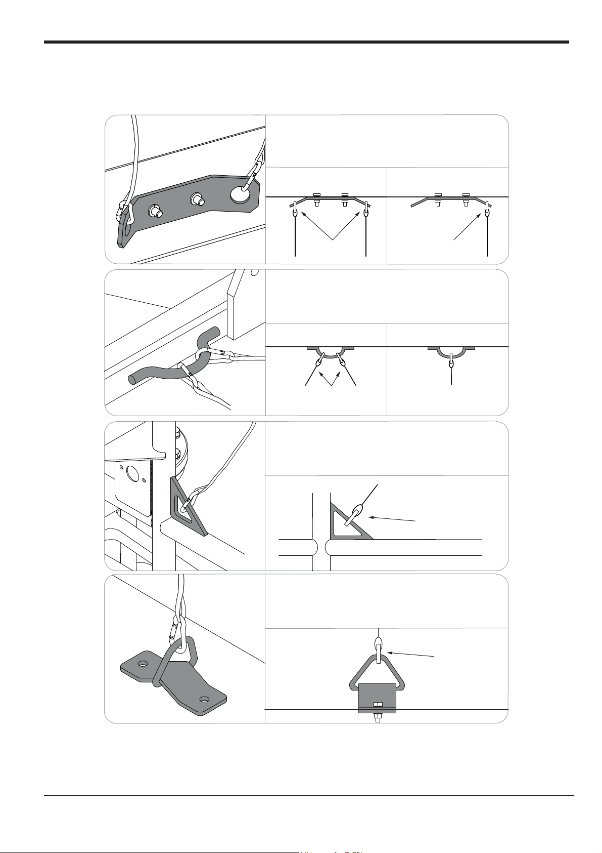
Harness attachment points are provided in the platform and the manufacturer recommends the usage of a fall
Safety Rules
restraint harness, especially where required by national safety regulations.
All harness attachment points on SNORKEL vehicles have been tested with a force of 3,650 lbs (16.3 KN)
per person.
See below examples of harness attachment points used on SNORKEL vehicles with their corrosponding rating;
Harness attachment point Type 1. is rated for one
lanyard attachment per loop as shown in the
illustrations depending upon platform occupancy rating
(see operators manual & decals).
Top View Top View
Top View
Type 1.
Type 2.
2 lanyard
attachments
Harness attachment point Type 2. is rated for two
lanyard attachments per loop as shown in the
illustrations depending upon platform occupancy rating
(see operators manual & decals).
Top View
2 lanyard
attachments
Harness attachment point Type 3. is rated for one
lanyard attachment per loop as shown in the
illustrations depending upon platform occupancy rating
(see operators manual & decals).
Front View
1 lanyard
attachment
Top View
1 lanyard
attachment
1 lanyard
attachment
Type 3.
Harness attachment point Type 4. is rated for one
lanyard attachment per loop as shown in the
illustrations depending upon platform occupancy rating
(see operators manual & decals).
1 lanyard
attachment
Type 4.
NOTE: There can be more harness attachment points per machine than the
maximum number of occupants allowed in a platform. Refer to
the platform decal & specifications table listed in the operators
manual for the correct occupancy rating before use.
iiiA38E Work Platform
Page 6

NOTES:
iv A38E Work Platform
Page 7
Foreword
Introduction
HOW TO USE THIS MANUAL
This manual is divided into 7 Sections,
The right hand pages of each Section is marked with a black
section number printed at the top corner of each page which
can be used as a quick guide.
SPECIAL INFORMATION
D A N G E R
Indicates an imminently hazardous situation which, if not avoided, will
result in severe injury or death.
W A R N I N G
Indicates a potentially hazardous situation which, if not avoided, could
result in severe injury or death.
C A U T I O N
Indicates a potentially hazardous sit uation which, if not avoided, may
result in minor or moderate injury.
General Description & Machine Specifications.
Information on the preparation for use, shipment,
Introduction &
Specifications
Machine Preparation
forklifting, transporting and storage.
Operation
Operating Instructions & Safety Rules.
1.0
2.0
3.0
WORKSHOP PROCEDURES
C A U T I O N
Detailed descriptions of standard workshop
procedures, safety principles and service operations
are not included. Please note that this manual does
contain warnings and cautions against some specific
service methods which could cause personal inju
could damage a machine and make it unsafe.
Please understand that these warnings cannot cover
all conceivable ways in which service, whether or not
recommended by Snorkel, can be done, or the possible
hazardous consequences of each conceivable way,
nor could Snorkel investigate all ways. Anyone using
service procedures or tools, whether or not recom-
mended by Snorkel, must satisfy themselves
thoroughly that neither personal safety no
safety will beorjeopardised.
Notes: Give helpful information.
All information contained in this manual is based on the
t product information available at the time of printing.
lates
We reserve the right to make changes at any time without
notice. No part of this publication ma
stored in retrieval system, or transmitted, in any form by
any means, electronic, mechanical, photocopying,
recording, or otherwise, without prior written permission of
the publisher. This includes text, figures and tables.
y be reproduced,
ry,
r machine
Maintenance
Preventative Maintenance & Service Intervals.
Troubleshooting
Causes of and Solutions to typical problems.
Schematics
Schematics and Valve Block Diagram with
description and location of components.
Illustrated Parts
4.0
5.0
6.0
Breakdown
Complete parts lists with illustrations.
7.0
vA38E Work Platform
Page 8

NOTES:
Foreword
vi A38E Work Platform
Page 9

Section
No.
Contents
Table of Contents
Page
No.
Section
No.
Section
i
Page
No.
1.0 Introduction & Specifications
1.0 Introduction ........................................................ 1-1
Purpose ..........................................................1-1
Scope ..............................................................1-1
1.1 General Information .......................................... 1-1
Platform ..........................................................1-1
Control Box ....................................................1-1
Elevating Assembly ..................................... 1-1
Rotation Gear ................................................ 1-1
Drive & Steer Systems .................................1-2
Power System ................................................1-2
Control System ............................................. 1-2
Chassis ...........................................................1-2
A38E Purpose & Limitations ...................... 1-2
1.2 Specifications ..................................................... 1-3
1.3 Notes .....................................................................1-4
2.0 Machine Preparation
2.1 Preparation For Use ......................................... 2-1
2.2 Preparation For Shipment ............................... 2-1
2.3 Forklifting The Work Platform ........................ 2-1
2.4 Lifting The Work Platform ................................ 2-1
2.5 Transport by Truck .............................................2-1
2.6 Manual Brake Release ......................................2-2
2.7 Storage .................................................................2-2
2.8 Notes .....................................................................2-3
3.0 Operation
3.0 Introduction ........................................................ 3-1
General Functioning .....................................3-1
Driving ........................................................... 3-1
Steering .......................................................... 3-1
Operating the Booms ...................................3-1
Design Features ............................................3-2
3.1 Safety Rules & Precautions ............................. 3-3
3.2 Controls & Indicators .......................................3-4
3.3 Pre-Operation Inspection .................................3-6
System Function Inspection .......................3-6
3.4 Opertaion ............................................................ 3-7
Elevating & Lowering
A38E Work Platform ................................. 3-7
Travel With The Work Platform
Lowered ..................................................... 3-7
Travel With The Work Platform
Elevated ..................................................... 3-8
Levelling ........................................................ 3-8
Emergency Situations &
Emergency Override .................................3-8
Emergency Lowering ......................3-8
Control From Ground Level ........................ 3-9
After Use Each Day ..................................... 3-9
Manual Rotation ...........................................3-9
Manual Telescopic Retraction ....................3-9
3.5 Notes .....................................................................3-11
The
4.0 Maintenance
4.0 Introduction ........................................................ 4-1
Tools Required ..............................................4-1
4.1 Preventative Maintenance ............................... 4-1
Preventative Maintenance
Table Key ....................................................4-2
Preventative Maintenance
Report ..........................................................4-2
4.2 Battery Maintenance .........................................4-3
Battery Inspection & Cleaning ...................4-3
Battery Charging .......................................... 4-3
Battery Cell Equalization ............................. 4-4
4.3 Temperature Correction For
Electrolyte Readings ......................................4-4
4.4 Lubrication ......................................................... 4-5
Grease Fittings .............................................. 4-5
Slew Ring .......................................................4-5
Pivot Pins .......................................................4-5
Hydraulic Oil Tank & Filter ......................... 4-5
4.5 Setting Hydraulic Pressures ............................ 4-6
Main Relief Valve ..........................................4-6
Slew Cross-Line Relief Valve ...................... 4-7
4.6 Maintenance on Elevating Assembly ............. 4-7
Installation of Elevating Assembly
Support ......................................................
Removal of Elevating Assembly
Support ....................................................... 4-7
4.7 Switch Adjustments ............................................ 4-8
Tilt Sensor ..................................................... 4-8
Boom Rest Limit Switch ... ...........................4-8
4.8 Hydraulic Manifold ........................................... 4-10
Removal ......................................................... 4-10
Disassembly ..................................................4-10
Cleaning & Inspection .................................4-10
Assembly .......................................................4-10
Installation .....................................................4-10
4.9 Hydraulic Pump ................................................. 4-12
Removal ......................................................... 4-12
Installation .....................................................4-12
4.10 Traction Motor Maintenance .......................... 4-12
Inspecting the Drive Motor ........................4-12
4.11 Electric Motor .................................................... 4-14
Troubleshooting ...........................................4-14
Disassembley ................................................ 4-14
Inspection ......................................................4-14
Reassembley ................................................. 4-14
Maintenance Intervals & Procedures ....... 4-15
4.12 Drive Reduction Gearbox .................................4-17
Changing the Oil ...........................................4-18
4.13 Torque Specifications ........................................4-18
4.14 Lower Lift Cylinder ............................................4-19
Removal ......................................................... 4-19
Disassembly ..................................................4-19
Cleaning & Inspection .................................4-19
Reassembly/Seal Replacement ...................4-20
.4-
7
IA38E Work Platform
Page 10

Section
i
Sect ion
No.
Contents
Table of Contents
Page
No.
Sect ion
No.
Page
No.
Installation .....................................................4-20
4.15 Upper Lift Cylinder ............................................4-21
Removal ......................................................... 4-21
Disassembly ..................................................4-21
Cleaning & Inspection .................................4-21
Reassembly/Seal Replacement ................... 4-21
Installation ........................
4.16 Telescopic Cylinder ........................................... 4-22
Removal .........................................................4-22
Disassembly ..................................................4-23
Cleaning & Inspection .................................4-23
Reassembly/Seal Replacement ................... 4-23
Installation .....................................................4-23
4.17 Steering Cylinder ........
Removal .........................................................4-23
Disassembly ..................................................4-23
Cleaning & Inspection .................................4-24
Reassembly/Seal Replacement ................... 4-24
Installation .....................................................4-24
4.18 Master Levelling Cylinder ............................... 4-25
Removal ..............................
Disassembly ..................................................4-25
Cleaning & Inspection .................................4-25
Reassembly/Seal Replacement ................... 4-25
Installation .....................................................4-25
4.19 Slave Levelling Cylinder ..................................4-26
Removal ......................................................... 4-26
Disassembly .............................
Cleaning & Inspection .................................4-26
Reassembly/Seal Replacement ................... 4-26
Installation .....................................................4-27
Bleeding the Master/Slave
Levelling Circuit ........................................4-27
4.20 Adjustment Of Overcentre Valves .................... 4-28
4.21 Replacing GP400 control module ....................4-29
4.22 Calibration of load cell ...................................4-30
.............................4-22
.......................................4-23
........................... 4-25
.....................4-26
5.0 Troubleshooting
7.0 Illustrated Parts Breakdown
7.0 Introduction ........................................................7-1
7.1 Index ..............
7.2 Illustrated Parts Breakdown .......................... 7-2
F inal Assembly A38E ................. ................................ 7-2
Chassis Ass embly .......................................................... 7-4
A38 PG Parts Assembly .................... ..... ....... .. ... .......... 7-6
Booms and Posts Assembly ..... .......... ............ ..... .......... 7-8
Cage and Cradle Assembly.................................................... 7-
Cage and Cradle Assembly (Rotator) ................................... 7-
Wheel Hub Assembly .......................................................... 7-
Drive Reduction Gear box Assembly .................................. 7-
Traction Motor Assembly (514274-000)............................. 7-
Traction Motor Assembly (512944-000).............................
Motor / Pump Assembly..................................................
Re ar & Front Wheel Kit .................................................
Worm Drive Unit & Slew Bearing.......................................
Manifold
Lower Lift Cylinde r Assembly.............................................
Upper Lift Cylinder Assembly ............................................
Telescopic Cylinder Assembly.............................................
St eeri ng Cylinder Assembly................................................
Master / Slave Cylinder Assembly......................................
Lower Control Box Assembly ............................................ 7-
Upper Control Box Assembly (CE)..................................... 7-
Upper Control Box Assembly (ANSI).................................
Cables & Electrical Components..........................................
Hose Ass embly...................................................................
Decal Kit - ANSI Version ...............................................
Decal Kit - CE Version ....................................................
Options List ..........................................................................
Block Assem
....................................................... 7-1
bly ...............................................
77-
7-
77-
7-
7-
77-
7-
7-
77-
7-
7-52
7-54
10
12
14
16
18
20
22
24
26
28
30
32
34
36
38
40
42
44
46
48
50
5.0 Introduction ........................................................5-1
General Procedure ........................................ 5-1
Special Tools .... ............................................ 5-2
Adjustment Procedures .......... ..................... 5-2
Checking Pump Preasure...............................5-2
Diagnostics using Ezcal display......... .......... 5-2
5.1 Troubleshooting Guides ....... .................... 5-4
5.2
I/O Matrix ..................................................... 5-3
Replacing the GP400 Control module ....... 5-6
GP400 I/O Allocations...............................
Notes ........................................................
5-7
5-8
6.0 Schematics
6.0 Introduction ........................................................6-1
6.1 Electrical Schematics ........................................6-3
6.2 Hydraulic Schematics ....................................... 6-6
II A38E Work Platform
Page 11

NOTES:
Contents
Section
i
IIIA38E Work Platform
Page 12

Section
i
NOTES:
Contents
IV A38E Work Platform
Page 13
Introduction & Specifications
Section
1.0
1.0 Introduction
PURPOSE
The purpose of this Service & Parts Manual is to
provide instructions and illustrations for the operation
and maintenance of the A38E Work Platform
manufactured by Snorkel. (See Figure 1-1).
SCOPE
The manual includes the procedures and
responsibilities which must be strictly adhered to for
proper operation, maintenance, adjustment, and
repair of this product. The Maintenance Section
further covers preventative maintenance and trouble
shooting.
1.1 General Information
The A38E is a quickly deployable self propelled aerial
work platform, designed to raise a specified number
of operators with hand tools to a work height of up
to 13.45 m (44.12ft.) i.e. a platform floor height of
11.45 m (37.56 ft.). It is designed to provide mobility
with the Platform in the raised or lowered position,
although travel with the Platform raised is limited to
a low speed. The boom assembly and telescope
functions are operated by a hydraulic pump driven
by a DC electric motor. Two DC electric traction
motors coupled to two braked gearboxes regulate
the drive function.
CONTROL BOX
The control box is permanently fitted at the front
centre of the platform. It features a Joystick which
will provide proportional control for raising or
lowering either of the
retracting the Telescopic Boom, rotating (slewing)
the entire Booms & Posts Assembly or driving.
A safety feature which is incorporated into the
Joystick’s operation is the Interlock Switch. This
must be activated at all times while operation is
required. This allows for one-handed operation. A
complete explanation of control functions can be
found in Section 3.
two booms, extending or
ELEVATING ASSEMBLY
The platform is raised and lowered by a combination
of two steel lift booms and one telescopic boo
each of which is operated by a hydraulic cylinder
which in turn is actuated by hydraulic power from the
motor driven pump. Solenoid operated valves control
to which cylinder the hydraulic oil is directed. Each
cylinder features an integral holding valve to prevent
uncontrolled descent in the case of a hose burst.
m,
ROTATION GEAR
The Booms & Posts Assembly can be rotated to
provide up to 5.6 m (18.4 ft.) of side outreach,
measured from the centreline of rotation to the front
of the Platform. This is do
hydraulic motor driving a Worm Drive Unit, around a
large diameter Slew Gear.
1.
ne by means of an integral
6.
2.
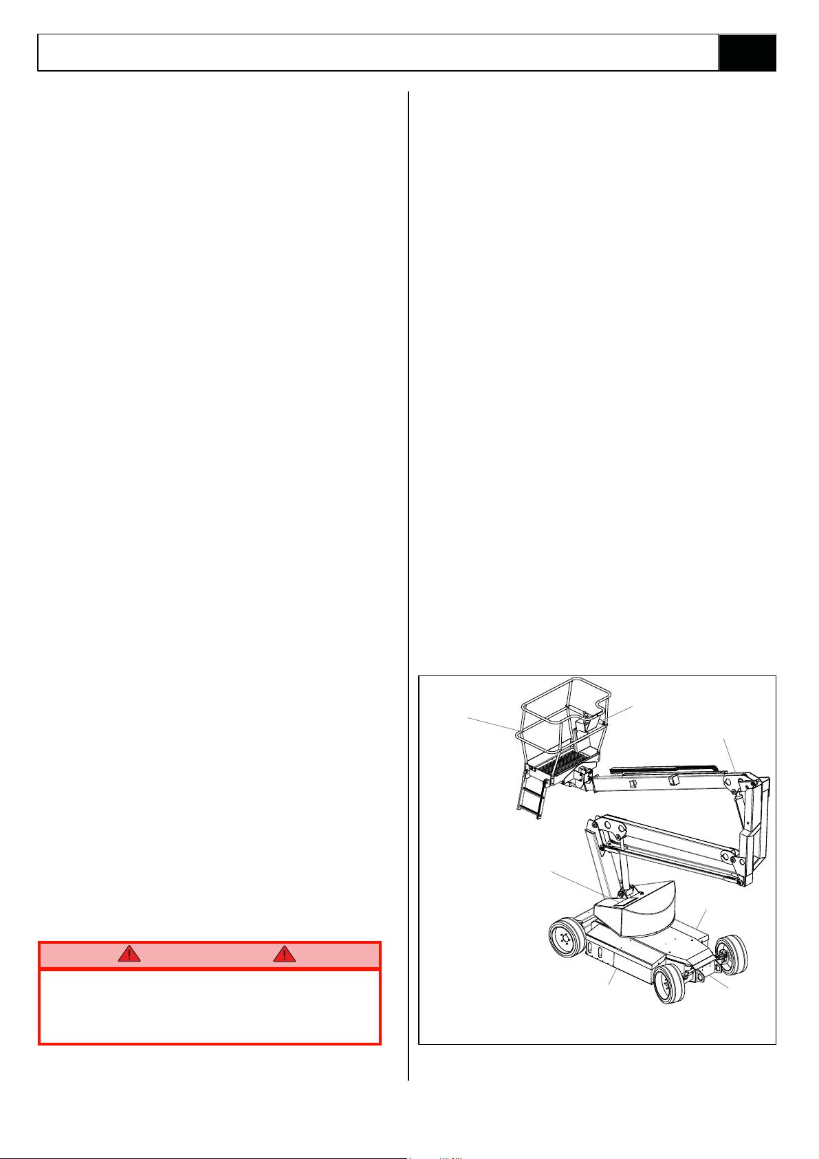
PLATFORM
The platform is large enough for a specified number
of operators and has a free-draining perforated floor
with 150 mm (5.9inches) toe boards. Hand rails are
constructed from steel tubing and a safety drop-bar is
provided at the entrance. Safety harness anchor points
are also fitted in the floor of the platform. The primary
Control Box is fitted permanently within this platform.
W A R N I N G
DO NOT begin using the machine until the
platform entrance drop bar is in the fully
lowered position.
7.
1. Pl atform
2. Elevating Assembly
3. Chassis
4. Power Module
5. Control Module
6. Platform Control Box
7. Lower Control Box
Figure 1-1: A38E Work Platform
5.
3.4.
1-1A38E Work Platform
Page 14

Section
1.1
Introduction & Specifications
DRIVE & STEER SYSTEMS
The A38E Work Platform is restricted to low speed
drive when the Platform is raised above the Boom
Rest Limit Switch. The Traction controller controls the
application of drive from the Joystick by means of two
ction Motors, which are assembled to the drive
Tra
wheels via a Drive Reduction Gearbox.
Steering of the A38E Work Platform is controlled by
a double acting cylinder. An Operator can Steer left
or right by depressing the Rocker Switches on top of
the Joystick, while activating the Interlock Switch.
POWER SYSTEM
The power system incorporates eight 6V batteries
driving the drive traction motors, or the 4kW (5.4HP)
electric motor which in turn drives the hydraulic
pump. The application of this hydraulic pressure is
performed by the Control System.
CONTROL SYSTEM
The machine is provided with fully proportional
controls by means of the interaction between a
P600, electron tor om ci contro l a dna rel proportional
joystick. The P600 and motor controller regulate the
drive motor/pump speed and hence the flow of oil
reaching the cylinders, the Worm Drive Unit or the
Drive Reduction Gearbox. It regulates the direction of
flow of the hydraulic oil via the solenoid valves located
on the manifold block, and it also monitors the operation of all switches on the machine via the machine
harness system.
The motor control units are located, in the left hand
chassis mo
hydraulic tank. This is accessible by removing the
main cover.
dule. The manifold block is located on the
A38E PURPOSE & LIMITATIONS
The purpose of the A38E work platform is to provide a
quickly deployable variable height work platform. It is
capable of lifting a specified number of people with work
tools up to an upper limit of 215 kg (ANSI 475 lbs) in
total. The unit will provide the ability to reach over
obstacles but must be used on firm level ground.
See Specification table on page 1-3.
The platform must only be used on firm level or slightly
uneven ground capable of supporting the maximum load
generated under the four wheels. Do not use on soft or
severely sloping ground.
DANGER
NOTE: It should be recognised that if the tilt
switch senses a degree of slope greater than
3º the elevating circuits will lockout and
sound a warning alarm. The Emergency
Override should then be used, to lower the
Elevating Assembly.
CHASSIS
The chassis is a structural frame designed to support
all the components of the A38E Work Platform.
1-2 A38E Work Platform
Page 15

Introduction & Specifications
1.2 Specifications
ITEM METRIC IMPERIAL (ANSI)
Duty Cycle 45% of 8 hour shift 45% of 8 hour shift
Platform Size
Max. Platform Capacity 2
Indoors
Outdoors
Maximum Working Height
Maximum Platform Height
Min. Platform Floor Height
Max. Working Outreach
Platform Height At
Maximum Outreach
Stowed Dimensions
Length
Width
Height
Ground Clearance 0.12 m 0.39 ft
heel Base x Gauge 2.00 m x 1.27 m 6.56 ft x 4.16 ft
W
Rotation
Unloaded Weight
With Load/ Max Weight
Drive Speed Stowed 0 - 4 km/h 0 - 2.49 mph
Drive Speed Elevated
Maximum Gradeability 36% 36%
Inside Turning Radius
Outside Turning Radius 2.40 m 7.87 ft
Power Source
System Voltage Control 12V 12V
Battery Charger
Hydraulic Oil Tank Capacity
Max. Hydraulic Pressure
Hydraulic Oil Grade
Cylinder Types
Control System
Wheels/Tyres
Braking
Table 1-1: Specifications
0.58 m x 1.3 m (inside gaurdrails) 1.77 ft x 4.3 ft (inside gaurdrails)
15 kg 475 lbs
2 People 2 People
1 People
13.45 m
11.45 m
0.65 m
6.10 m 20.00 ft
5.40 m 17.72 ft
4.04 m
1.50 m
2.00 m
362 degrees non-continuous 362 degrees non-continuous
3,770 kg 7
3,985kg 8,840 lbs
0 - 0.4 km/h 0 - 0.25 mph
0.40 m 1.31 ft
48V DC 4kW, 8 X 6V 210Ah Batteries 48V DC 5.4HP, 8 X 6V 210Ah Batteries
Auto Dual AC input 100-240V ~ 50/60Hz 18A
Output 48V, 25A
25 Litres 6.5 Gallons US
145 bar 2105 psi
ISO #46 ISO #46
2 Double Acting Lift Cylinders With
Lock Valves And Manual Emergency
Lowering Facility.
1 Double ActingTelescopic Cylinder
Refer to Section 5 of the Service &
Parts Manual
One handed Proportional Joystick
Operating Energy Efficient Motor
Control System
400 mm Diameter Steel Disc Wheel
With Solid All Surface Tyres
Automatic Spring Applied
Hydraulic Release
Auto Dual AC input 100-240V ~ 50/60Hz 18A
Output 48V, 25A
2 Double Acting Lift Cylinders With
Lock Valves And Manual Emergency
1 Double ActingTelescopic Cylinder
Refer to Section 5 of the Service &
One handed Proportional Joystick
Operatin
15.75 inch Diameter Steel Disc Wheel
With Solid All Surface Tyres
Automatic Spring Applied
2 People
44.12 ft
37.56 ft
2.13ft
13.25 ft
4.92 ft
6.56 ft
,826 lbs
Lowering Facility.
Parts Manual
g Energy Efficient Motor
Control System
Hydraulic Release
Section
1.2
Max Noise Lev el
69.5 dB(A) 69.5 dB(A)
1-3A38E Work Platform
Page 16

Section
1.3
NOTES:
Introduction & Specifications
1-4 A38E Work Platform
Page 17
Machine Preparation
2.1 Preparation for use
CAUTION
Read, understand and follow all operating
instructions before attempting to operate the
machine.
2.2 Preparation for Shipment
1. Lubricate machine per lubrication instructions in
Section 4.4, Maintenance.
2. Fully lower the platform and make sure the
machine is stowed securely.
3. Check that the hydraulic oil level is adequate
and that it is not over filled.
Check that the batteries are charged and disconnect
the batteries usin
This prevents excessive power drain prior to next
using the machine.
g the Battery Disconnect Plug.
FORKLIFT
HERE
Section
2.1
Front Lifting /
Tie-down Lug
2.3 Forklifting the Work Platform
CAUTION
The A38E is not designed to be consistently
forklifted. This operation can be used for very
short distances only.
Forklift from the side by lifting under the chassis
modules as per Figure 2-1. When lifting the A38E
with a forklift, great care should be taken not to
damage the right or left hand modules as these
contain sensitive equipment.
2.4 Lifting the Work Platform
CAUTION
See specifications (Section 1.2) for the
weight of the work platform and be certain
tha
t lifting apparatus is of adequate capacity
to lift the platform.
The A38E may be lifted by an overhead hoist/crane in
the following manner:
Four lifting straps capable of safely supporting the
total weight of the A38E ( (3,770 Kg /7,430 lbs CE
Rear Lifting /
Tie-down Lug
Figure 2-1: Forklifting & Lifting the A38E
Version & 4,010 Kg /8,840 lbs ANSI Version) and at
least 250 cm (8 ft.) long are required. This minimum
length is important to ensure the correct lifting an
The straps should be positioned at the Lifting/Tie
Down Lugs as shown in Figure 2-1. Great care must
be taken to avoid damage to any of the components
of the machine.
gle.
2.5 Transport by Truck
The A38E is normally carried upon a suitably rated
transportation vehicle. Because of the high
gradeability of the A38E it will be capable of driving
directly on to most vehicles. If however the loading
slope is greater than the gradeability or the batteries
have been depleted sufficiently a winch sho
used. The procedure when using a winch is to
disengage the gearbox from the drive wheels using
the Allen key release, and then winch the machine on
to the vehicle in its freewheel state.
Refer to Section 2.6 which follows.
uld be
2-1A38E Work Platform
Page 18
Section
2.6
Machine Preparation
When the A38E is on the Truck it should then be
made secure.
1. Chock the wheels of the A38E.
2. Secure the work platform to the transport
vehicle with chains or straps of adequate load
capacity attached to the lifting lugs on the
chassis.
CAUTION
Overtightening of the chains or straps through
tie down lugs may result in damage to the
Work Platform.
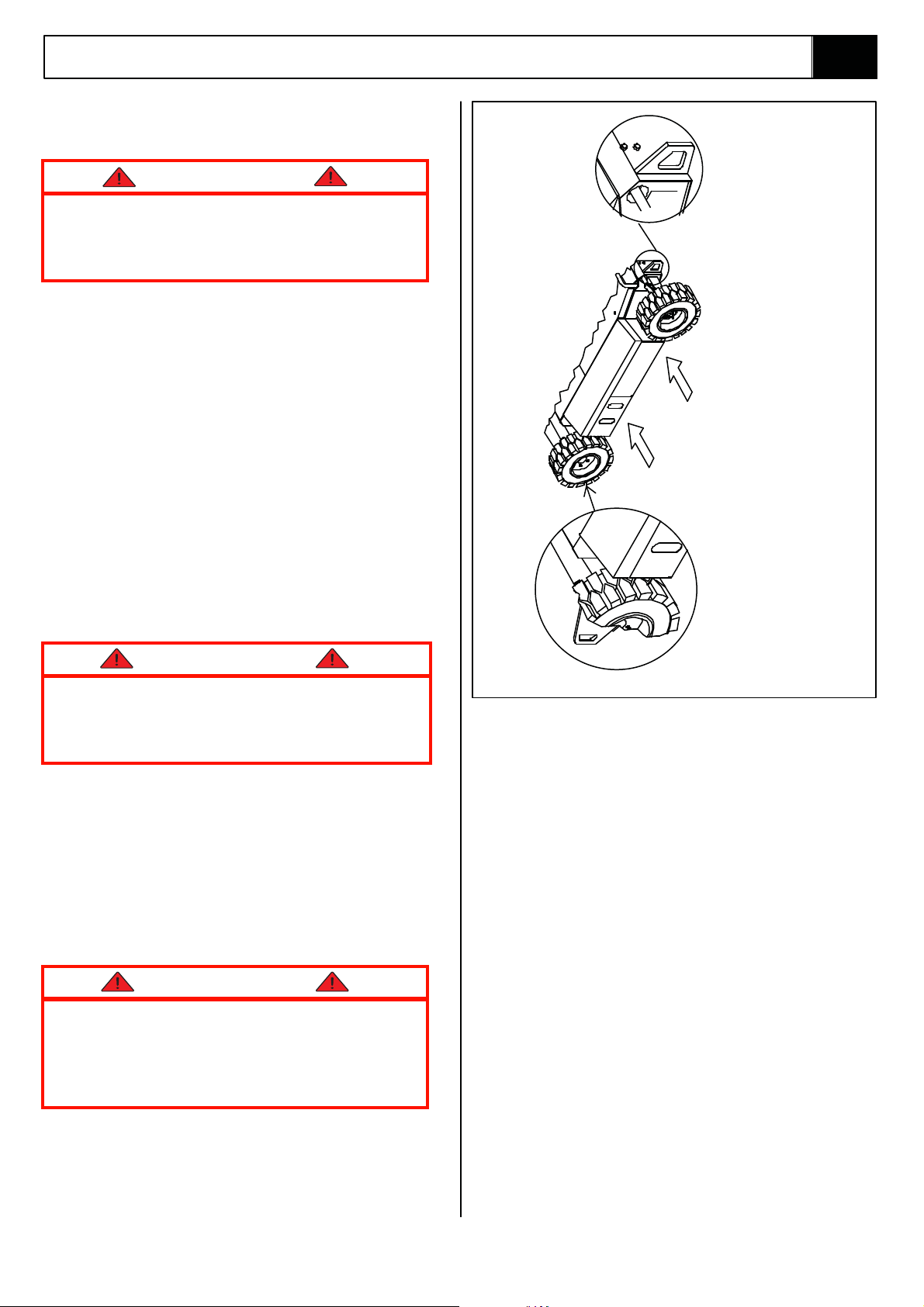
2.6 Manual Brake Release
CAUTION
Perform this operation only when the machine
will not operate under its own power and it is
necessary to move the mach
winching onto a trailer for transportation.
Ensure the machine is on level ground before
commencing this operation and use wheel
chocks as appropriate to prevent the machine
from rolling inadvertently.
Do not exceed 3 mph. Faster speeds will
damage drive components and void warranty.
1. Ensure that the Platform is fully lowered and
that the Elevating Assembly is slewed (rotated)
such that the platform is stowed above the drive
wheels. Turn the Upper Control Box to the OFF
tion and remove the key.
posi
2. Attach a chain/cable of sufficient capacity for
towing the machine to the front or rear lifting/tie
down lugs. Take up the slack in the chain/cable.
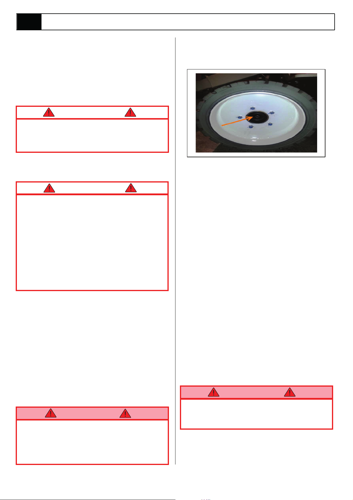
3. Locate the Allen head socket screws located in
the centre of the two drive (rear) wheels and
using a 6 mm Allen key, turn each one
clockwise to its full extent. The machine is now
in freewheel mode.
WARNING
DO NOT leave the machine unattended or
attempt to operate the A38E Work Platform
until the Brake Rele
re-engaged.
ase Screws
ine, or for
have bee
n
4. When towing is completed, turn both Allen head
socket screws in a counter clockwise direction
until they rest firmly against the locking circlip.
Figure 2-2 : Manual Brake Release
2.7 Storage
No preparation is required for storage when the Work
Platform is in regular use. Regular maintenance per
Table 4-1 should be performed.
If the work platform is to be placed in long term
storage (dead storage) use the following preservation
procedure.
PRESERVATION
1. Clean painted surfaces. If the painted surface is
damaged, repaint.
2. Fill the hydraulic tank to operating level with the
platform fully lowered. Fluid should be visible
on the Di
hydraulic fluid be drained.
3. Coat exposed portions of cylinder rods with a
preservative such as multipurpose grease and
wrap with barrier material.
4. Coat all exposed unpainted metal surfaces with
preservative.
BATTERIES
1. Disconnect the batteries.
2. Disconnect the battery leads and secure to the
chassis.
Care should be taken, while disconnecting the
battery leads, that a short circuit does not occur.
i.e. grounding to the chassis with a
3. Remove the batteries and place in alternate
service. Battery efficiencies are best realised
when used consistently.
p Stick. It is not recommended that the
WARNING
spanner.
2-2 A38E Work Platform
Page 19

NOTES:
Machine Preparation
Section
2.7
2-3A38E Work Platform
Page 20

Section
2.7
NOTES:
Machine Preparation
2-4 A38E Work Platform
Page 21
Operation
Section
3.0
3.0 Introduction
GENERAL FUNCTIONING
WARNING
Before beginning to operate the machine it is a
mandatory requirement to read, fully understand
and follow the Operators Manual.
The A38E Lift and Steer functions are operated by
utilising a battery powered electric motor which
drives a hydraulic pump. The pump supplies oil
under pressure to the various platform functions.
electrically activated solenoid valves (the control
of which solenoid valve activates and the rate at
electrical circuit, and its components).
The Drive function is operated by utilising two drive
motors which
Motor Controller.
NOTE:
An Interlock Trigger Switch is an integral part of the
Joystick. This must be depressed for the functions to
operate. This will energise the Line Contactor and enable
electrical control. (This safety feature prevents
inadvertent activation of all powered functions, in the
case of accidental movement of the Joystick.)
DRIVING
Platform controls provide variable speeds for the
drive function through the use of a Joystick. This is
achieved using a motor control unit which varies the
speed of the two DC electric traction motors. To drive
the A38E there are a number of steps which need be
taken. First the operator should ensure that neither of
the Emergency Stop Buttons are pressed, then the
Keyswitch on the ground control panel should be
turned to the
Momentarily operate the drive
the A38E will be able to drive.
The machin
to the angle of the Joy-
position, while the
depressed. The speed range within which the machine
will drive is deter-mined by whether or not the booms
are raised.
are controlled by a Electronic Traction
‘PLATFORM CONTROL’ position.
function switch and
e will then drive at a speed proportional
stick
from the neutral (centre)
Joystick Interlock Switch is
If a boom is raised off the Boom Rest Limit Switch
the current to the drive motors will be reduced leading
to a significantly slower drive speed. This is a safety
feature. The drive wheels are driven by two DC
electric traction motors coupled to two braked
gearboxes. When the Joystick is in the neutral
position the brake chamber is free of oil and the
internal spring within the gearbox maintains the
braking pressure. Upon moving the Joystick the
brake chambers will receive a flow of pressurised
oil which will release the brakes.
STEERING
Platform controls also provide a steering function
through the use of ‘Rocker’ activated Steering
Switches in the Joystick. This is achieved by using the
tla yb wolf ciluardyh eht seirav hci 006P wh ering
the voltage to the pump. To steer the A38E there are
a number of steps which need be
First the operator should ensure that neither of the
Emergency Stop Buttons are pressed, then the
Keyswitch ground control Panel should be turned to
‘PLATFORM CONTROL’ position.
the
Momentarily operate the drive function switch to drive
and the A38E will also be able to steer. To steer the
machine the Rocker should be pushed to the left or
the right, while the Joystick Interlock Switch is
depressed. Steering left or right will energise the
steering coils and allow oil to enter the full bore side
or annular side of the steering cylinder, there by
turning the wheels in the chosen direction. The
orientation of the Platform to the Chassis will
determine the direction the machine will travel when
the Joystick is engaged.
NOTE:
Steering is not self-centring. The wheels must be
returned to the straight ah
Steering Switch.
ead position by operating the
taken.
OPERATING THE BOOMS
Boom functions, including the telescopic and slewing
functions, can be operated either from the Platform
Controls or the Chassis Controls.
The Platform controls provide variable speeds for the
boom functions through the use of a Joystick. This is
deeps eht seirav hcihw 006P na gnisu deveihca
of the motor/pump unit and increases
the flow of oil to the different functions. This control
t receives a control signal from the Joystick on the
uni
upper controls, the speed of the motor will increase
as the Joystick is pushed further away from the
neutral (centre) position.
or decreases
3-1A38E Work Platform
Page 22

Section
3.0
Operation
It will be noticed that on the Upper Control Box a set
of switches are used to alternate functions. Each
function will have it’s corresponding graphicand lamp.
This selector switch indicates to the Controller which
function is required and by using the Joystick the
speed of this selected function can be adjusted.
The boom functions on the chassis controls provide
proportional control for each function by way of an
analog rocker switch, the desired function can be
activated by holding on
controls and and operating the analog rocker, the
one of four switches on the
the four switchs act as both selector & enable
switches.
The use of these functions is further explained
throughout this Section.
DESIGN FEATURES
The A38E Series Work Platform has the following
features:
The drive speed is limited to a ‘creep speed’ when
operating the Work Platform while the machine is
elevated.
The energy-efficient motor control units provides
long battery life and smooth proportional control of
the boom and drive functions.
All cylinders are fitted with hydraulic hose-burst
protection interlocks.
The on-board charger is fully automatic and
charges the batteries efficiently and economically.
If the work platform starts to become unstable and
the Tilt Sensor is activated an alarm will sound in
the upper control box. In this situation power is
partially cut to the upper controls to prevent any
boom movements (i.e. UP, TELE OUT) that might
increase instability. An emergency override switch
is fitted to allow the booms to be lowered at a
controlled speed to bring the machine back to a
stable position.
In the event of a power loss the two Boom Lift
Cylinders are fitted with emergency lowering
valves which allow the booms to be lowered at a
controlled speed by an operator on the ground.
A Master Cylinder/Slave Cylinder levelling system
ensures that the Platform remains level throughout
the entire working cycle of the machine.
A manual rotation facility is fitted to allow rotation of
the Elevating Assembly in the event of power loss.
HOUR METER & BATTERY CHARGE
INDICATOR.
The A38E Series Work Platform is equiped with a
display in the chassis control panel which displays
total hours run & an Indication of remaining battery
charge.
LOAD SENSI NG
The A38E is fitted with a load sensing system designed to comply with the requirements of :
BS EN 280 : 2001
If a load equivelent to 99% of safe working load is
lifted an overload lamp will illuminate on the platform
control box.
If a load which is greater than the safe working load by
is present in the basket all machine functions will
10%
cease to operateand an acoustic warning will sound.
In order to return
les
s than the safe working load must be present in the
basket and
re-cycled by pushing the emergency stop button and
releasing it again.
to normal operation a load equal to or
the power must be re-cycled, power can be
3-2 A38E Work Platform
Page 23

Operation
Section
3.1
3.1 Safety Rules and Precautions
WARNING
Before using the A38E Work Platform it is
imperative to read, understand and follow the
following Safety Rules and Precautions.
NEVER operate the machine unless you have been
fully trained in its safe use, are medically fit and have
read and fully understood these instructions.
NEVER leave the A38E unattended with the Platform
in the raised position.
ALWAYS position the machine on firm level ground
with a minimum bearing capacity of 78 kg /cm
(1109 psi).
CHECK that no
the machines range of movement.
DO NOT work within 3 metres (10 feet) of live
overhead cables. Set up warning tape barrier at the
safe distance.
(THIS MACHINE IS NOT INSULATED).
DO NOT exceed the safe working load of 215 kg,
(ANSI 475 lbs)
CE=max. 1 persons Outdoor + Tools 135Kg
2 person Indoor + Tools 55Kg
(ANSI=max. 2 person Indoor/Outdoor)
See specification table on page 1-3 .
overhead obstructions exist within
2
DO NOT use in winds exceeding 12.5 m/s (28 mph Beaufort Force 6)
NEVER change or modify operating or safety
systems.
INSPECT the machine thoroughly for cracked welds,
loose hardware, hydraulic leaks, damaged control
cable, loose wire connections and wheel bolts.
NEVER climb down an elevating assembly with
platform elevated.
NEVER perform service on or in the elevating
assembly while the platform is elevated without first
blocking the elevating assembly.
NEVER recharge batterie
flame; batteries under charge emit highly explosive
hydrogen gas.
SECURE the work platform against unauthorised use
by turning Keyswitch off and removing key from
switch.
NEVER replace any component or part with anything
other than original Snorkel replacement parts without
Snorkel’s consent.
NEVER leave the machine unattended while the
Gearbox Drive is disengaged.
s near sparks or open
NEVER sit, stand or climb on guard rail or midrail of
the platform.
NEVER use ladders or scaffolding on the platform.
DO NOT use the ma
application involving additional loads or forces. The
maximum side force must not exceed 200N
Outdoors / 400N Indoors, (ANSI = 90 ft. lbs).
DO NOT increase wind loadings by fitting items such
as sign boards, flags etc. to the cage or boom.
DISTRIBUTE all loads evenly on the platform. See
Table 1-1 for maximum platform load.
NEVER use damaged equipment. (Contact Snorkel
Ltd. for instructions).
NEVER attach overhanging loads or increase the
size
of the working platform.
chine as a crane or for any other
3-3A38E Work Platform
Page 24

Section
3.2
Operation
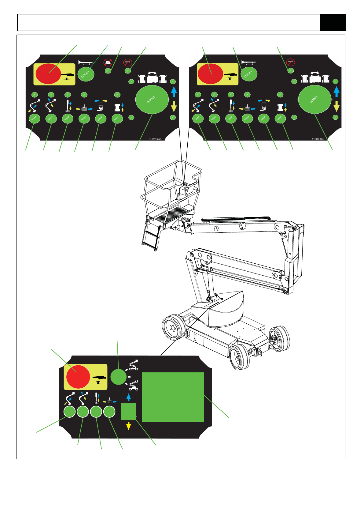
3.2 Controls and Indicators
The controls and indicators for operation of the A38E
Work Platform are shown in Figures 3-1 & 3-2. The
name and function of each control and indicator are
listed in Tables 3-1. The index numbers in the figure
correspond to the index numbers in the table. The
operator should know the location of each
control and indicator and have a thorough
knowledge of the function and operation of each
before attempting to operate the unit.
Table 3-1: Controls and Indicators
Platform Controller*
INDEX NO. NAME FUNCTION
1 Emergency Stop Cuts all Platform control functions when pushed, twist to release.
2 Platform Level Operate switch and hold while using joystick to level the platform.
Note: Platform Cylinders will keep the platform level during normal operation, if the
Platform goes out of level over time this function will return the platform to level.
3 Upper Boom Operate switch to engage Upper Boom lift functions (Up & Down)
4
5 Drive Operate switch to engage Drive functions (Forward & Reverse)
6 Horn Operate switch and hold to sound
7 Slew (Rotate) Operate switch to engage Slew functions (Clockwise & Counter Clockwise)
Low Boom
Operate switch to engage Lower Boom lift functions (Up & Down)
the horn.
8 Warning Lamp Low battery warning lamp. Machine must be charged.
9 Telescope Operate switch to engage Telescope functions (Extend & Retract)
10
11
Joystick Depress deadman switch and select joystick forward or reverse to enable a selected
function.
Overload warning lampWarning Lamp
Chassis Control
INDEX NO. N
1
2 Upper Boom Operate switch and hold to engage and enable Upper Boom lift functions (up & down)
3 Lower Boom Operate switch and hold to engage and enable Lower Boom lift functions (up & down)
4
5 Telescope Operate switch and hold to engage and enable Telescope functions (extend & retract)
6
8 Display In normal operation displays battery life and hour run. Can also be used to display
AME FUNCTION
mergen
E
Slew (Rotate) Operate switch and hold to engage and enable Slew functions (clockwise & counter
Key Switch Turns the machine OFF/ON and selects Platform or Chassis controls
Rocker Switch Use with “enable” switches to activate the selected f un
cy Stop
Cuts
all m
Clockwise.
diagnostics.
achine functions
ction7
Note:
Yellow and Blue direction arrows are included on the Control Panel to show the operator which way each
function will move when the joystick is moved in a particular direction.
3-4 A38E Work Platform
Page 25
Operation
CUTOUT
CUTOUT
CUTOUT
CUTOUT
CUTOUT
CUTOUT
Section
3.2
(CE)
4 4
3
1
7
6
11 8
2
5 109
1
512937-000
6
9
8
7 5 10
23
(ANSI)
3
1
6
0
8
512940-000
2
5
4
7
Figure 3-1: Controls & Indicators
3-5A38E Work Platform
Page 26

Section
3.3
Operation
3.3 Pre-Operation Inspection
W A R N I N G
Carefully read, understand and follow all
safety rules and operating instructions.
Perform the following steps each day before
use. DO NOT perform service on Work
Platform with the platform elevated unless the
elevating assembly is properly supported.
1. Remove module covers and inspect for
damage, oil leaks or missing parts.
2. Check the level of the hydraulic oil with the
platform fully lowered and the Telescopic Boom
fully retracted. Oil should be visible on the filler
cap dip stick. If ne
No. 46 hydraulic oil.
3. Check that the electrolyte level in the batteries
is correct. (Battery Maintenance, Section 4.3)
4. Verify batteries are charged.
5. Check that the A.C. extension cord has been
disconnected from charger.
6. Carefully inspect the entire machine for
damage such as cracked welds or structural
members, loose or missing parts, oil leaks,
damaged cables or hoses, loose connections
and tyre damage.
7. Move machine, if necessary, to unobstructed
are
a where machine can be fully elevat
8. Visually inspect the cylinders, hoses and cables
for damage. Check for missing or loose parts.
cessary top-up using ISO
ed.
15. Operate the manual telescopic retraction
system using the Handpump to test that it will
work. (Not required on
16. LOWER each boom until the Elevating
is fully stowed. Turn Keyswitch on the Lower
ANSI machines).
Assembly
Control box to the ‘LOWER CONTROL SELECTION’.
Climb into the
Platform and check that the
Platform is level.
If not adjust as shown in
Section of this manual. Repeat all the above
tests from the Platform Controls. Push the
Emergency Stop Button to identify that
functions will indeed cease when depressed.
Bring the machine back to the stowed position
and retract the Telescopic Cylinder.
17. PRESS the Service Horn to see that it is
operational
pressing the Joystick Interlock Switch slowly
PUSH the Joystick to DRIVE FORWARD, and
then PULL to DRIVE REVERSE, to check for
speed and proportional control. The farther you
push or pull the Joystick the faster the machine
will travel.
18. PUSH the Steering Switch RIGHT and then
LEFT to check for steering control.
19. RAISE the Elevating Assembly until the Boom
Rest Limit Switch is no longer activated and
then repeat the Drive Fun
speed (‘CREEP SPEED’) should be available.
The System Function Inspection is then complete.
. Select the DRIVE function. While
W A R N I N G
the Platform Levelling
ction test. Only low
SYSTEM FUNCTION INSPECTION
9. Turn both Chassis and Platform Emergency
Stop switches ON (rotate clockwise).
10. Turn Keyswitch on the Lower Control box to
the ‘LOWER CONTROL SELECTION’.
11. Using the chassis control switches, fully
ELEVATE Booms no. 1 & 2 and EXTEND the
Telescope.
12. SLEW the Elevating Assembly through 180
degrees in both directions.
13. Visually inspec
cage mounting/structure, lift cylinders, cables
and hoses for leaks, damage or erratic
operation. Check for missing or loose parts
such as nuts, bolts and circlips.
14. Test that the Emergency Lowering Valves on
each of the Lift Cylinders is operating correctly
as detailed in Section 3.4. PUSH the
Emergency Stop Button to identify that
functions will indeed cease when depressed.
t the elevating assembly and
If there are any concerns about the safe use
or operation of the A38E following this
Pre-Ope
ration Inspection DO NOT USE
THE A38E WORK PLATFORM. Contact your
supplier or Snorkel’s Product Support
Department.
3-6 A38E Work Platform
Page 27

Operation
Section
3.4
3.4 Operation
NOTE: Before operating the A38E Work Platform
it is imperative that the Pre-Operation Inspection
(Section 3.3) has been completed and any
deficiencies have been corrected. The operator
must also understand the functions of all the
controls before operating the machine.
ELEVATING & LOWERING THE A38E
WORK PLATFORM
Before beginning any operation involving the Elevating
Assembly the following checks should be carried out.
When the A38E has been thoroughly inspected the
elevating assembly can then be used.
W A R N I N G
LOOK up and around for obstructions before
performing the lift function.
ENSURE that the Elevating Assembly is
clear of the Chassis before engaging the
Slew operation.
DO NOT overload the platform
DO NOT operate within 3 metres (10 feet) of
any electrical power cables. THIS WORK
PLATFORM IS NOT INSULATED.
Cordon off the area within the platform’s
working area to keep passers-by clear of
the booms.
NOTE: Chas
1. Ensure the ‘CONTROL SELECTION KEYSWITCH’
is selected to ‘UPPER CONTROL’ and
emergency stop buttons are released (twisted clock-
wise).
Enter Platform through the entrance at the side
2.
of the A38E and ensure that the drop bar is in
the lowered position. Lock the Entry Step in the
raised position.
3. Before using the machine all local Safety
Regulations involving helmets and restraining
devices should be observed. Safety harness
lanyards, not exceeding 1 m (3 ft.) in length,
should be attached to anchor points in cage
floor.
4. Select “ LOWER BOOM ” on function selector
switch.Check for overhead obstructions and when
when satisfied squeeze the Joystick Interlock
control on.
sis controls are for service use only.
both
Slowly move the Joystick forwardto ELEVATE
the lower boom.
The further the joystick is moved, the faster.
the boom will move.
to
the Interlock at
required.
5. Select “UPPER BOOM ”, “TELESCOPE” or
“ROTATE” as required using the ‘Function
Selector Switches’ and operate as described
above. For boom functions the controls will
again be forward for UP and backward for
DOWN.
6. To rotate (SLEW) RIGHT the Controller
Joystick should be moved forward. Conversel
to rotate (SLEW) LEFT move the Controller
Joystick backward.
7. To ”TELESCOPE” IN the Controller Joystick
should be moved forward. Conversely to
”TELESCOPE” OUT move the Controller
Joystick backward.
8. Before lowering, check beneath the cage floor
for obstructions, operate as described above,
moving the Joystick back to lower the Booms.
Pressure must be applied
all times while operation is
TRAVEL WITH WORK PLATFORM
LOWERED
1. Verify that the chassis Emergency Stop Button
is in the
and that the Keyswitch is turned to the
‘UPPER CONTROL’position.
2. Climb into the Platform and check that the
Platform Emergency Stop Button is in the ‘ON’
position,
depressed. Ensure that the
lowered
3. Check that the route is clear of persons,
obstructions, pot holes or ledges and is capable
of supporting the wheel loads. Also, check that
the clearances above, below and to the side of
the Work Platform are sufficient.
4. Grasp the Joystick so that the Interlock Switch
is depressed (releasing this Interlock Switch will
cut power to the Joystick). Slowly push or pull
the Joystick to FORWARD or REVERSE to
travel in the desired direction. The farther you
push or pull the Joystick from the centre the
faster the machine will travel.
‘ON’ position (turn clockwise)
and that the Drive function button is
drop bar is in the
position.
y
3-7A38E Work Platform
Page 28
Section
3.4
Operation
5. To “STEER” the A38E activate the Interlock
Switch while pushing the Steering Switch LEFT
or RIGHT to turn the wheels. Observe the tyres
while manoeuvring to ensure proper direction.
NOTE:
Steering is not self-centring. The wheels must be
returned to the straight ahead position by operating
the Steering Switch.
TRAVEL WITH WORK PLATFORM
ELEVATED
W A R N I N G
Travel with platform elevated ONLY on firm
and level surfaces. Platform motion is
exaggerated whil
surfaces.
NOTE:
The Work Platform will travel at reduced speed when
in the elevated position.
1. Check that the route is clear of persons,
obstructions, pot holes or ledges and is capable
of supporting the wheel loads. Also, check that
the clearances above, below and to the side of
the Work Platform are sufficient.
2. Operate the Drive function switch.
3. Grasp the Joystick so that the Interlock Switch
is depressed (releasing this Interlock Switc
cut power to the Joystick). Slowly push or pull
the Joystick to FORWARD or REVERSE to
travel in the desired direction. The farther you
push or pull the Joystick from the center the
faster the machine will travel.
e travelling on uneven
h will
C A U T I O N
If the machine comes to a halt and the Tilt
Alarm sounds, immediately lower the
Platform and move the machine to a level
location before re-elevating the Platform.
PLATFORM LEVELLING
NOTE:
The Levelling function will only
Rest Limit Switch has been activated i.e. when the
Booms are stowed.
work when the Boom
The platform can be levelled from the Upper controls
using the levelling function, oper d oh ld thena eta
levelling switchon the upper control box (see fig3-1)
while moving the joystick forward or back to level the
platform. The switch should be operated in short
bursts to level the platform slowly.
EMERGENCY SITUATIONS &
EMERGENCY OVERRIDE
In any emergency situation, the first action to be taken
should be to hit the red “Emergency Stop”
button for instant cutout of all functions. It will then be
required to twist the button clockwise, this releases
the cutout and the machine can be operated again.
If the audible Tilt warning alarm sounds, normal
control functions will cease to operate. This will
due to the following problem ;
the machine is out of level i.e. Tilt Sensor has
been activated.
In this situation the only machine
operate are descent functions, descend to the ground
in a controlled manner and cycle the power (push and
release the emergency stop) to restore all functions,
move the machine to a level surface and continue
with normal operation.
Note that during emergency operation, controls
will operate at a fixed, slow speed and will not
allow the raising or extending of the Booms.
The Booms can be lowered or retracted.
functions that will
be
EMERGENCY LOWERING
C A U T I O N
When operating this function, extreme care
must be taken to ensur
carrying out the task does not become
trapped by the structure. DO NOT climb
down the Elevating Assembly to operate
these valves.
Should the machine become inoperable when
elevated, request a person on the ground to lower the
platform using the emergency lowering valves.
These are red knobs (push type) mounted at the
base of the 2 Main Hydraulic Lift Cylinders (See
Figure 3-2).
Operate the lower boom first by pushing slowly.
The boom will descend slowly. The speed
is controlled by retaining pressure on the valve -
e that the person
of descent
3-8 A38E Work Platform
Page 29
Operation
ens
ure a slow controlled rate of descent at all times.
Descent can be halted at any time by removing
pressure from the red knob.
Repeat the operation if necessary for the upper boom
when cylinder is in reach of the ground.
With both main booms lowered fully it should then be
possible to leave the platform safely.
Section
3.4
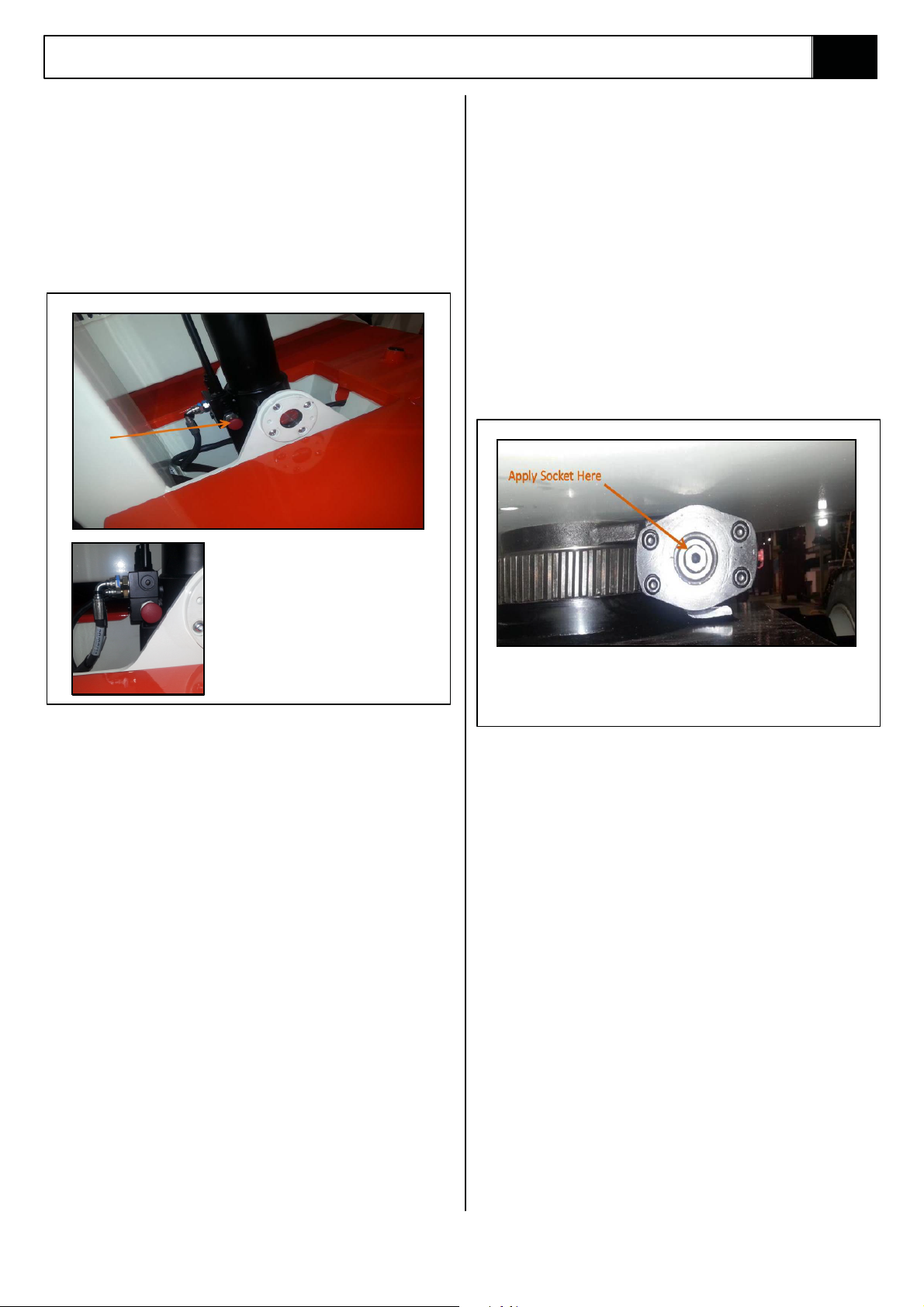
MANUAL ROTATION
1. Ensure booms are lowered as far as possible
using the emergency lowering valves, and that
the Emergency Stop Button is pressed to
prevent any accidental powered operation.
2. Apply a 7/8” socket wrench to shaft and turn to
rotate elevating assembly.
3. Remove wrench.
Before operating the Emergency
Lowering Valves the surrounding
area should first be cleared of any
potential obstructions. It is also
important that when the valve is
pushed, it is initially done slowly.
This is so that sudden movement
will not occur in the Elevating
Assembly, leading to a potentially
unstable machine.
Figure 3-2: Emergency Lowering
CONTROL FROM GROUND LEVEL
1. Chassis Controls are fitted at the base of the
Elevating Assembly. These should be used
when no operator is in the platform (for
maintenance/ service or inspection purposes),
or if the operator has become incapacitated.
For further information see Table 3-1.
2. Use the appropriate switch to raise or lower
Boom 1, Boom 2, Telescope or rotate as
required.
AFTER USE EACH DAY
1. Ensure that the platform is fully lowered.
2. Park the machine on level ground, preferably
undercover, secure against vandals, children or
unauthorised operation.
3. Turn key switch to OFF and remove key to
prevent unauthorised ope
4. Recharge batteries in accordance with
instructions in section 4.2.
ration.
the
To rotate the Elevating Assembly first apply a 7/8”
socket wrench to the shaft and turn to rotate the
Elevating Assembly. When finished remove the wrench.
Figure 3-3: Manual Rotation
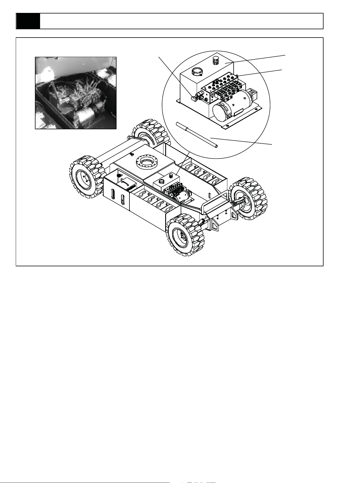
MANUAL TELESCOPIC RETRACTION
(SEE FIGURE 3-4)
NOTE:
Manual Tele Retraction is not required, and
not provided for ANSI machines.
In the event of loss of electrical power the Telescopic
Cylinder can be retracted as follows:
1. Remove the cover from the chassis body.
2. The Handpump is attached to the Main Manifold
Block. Remove the Handpump Handle from the
clips on the side of the Chassis and insert into
the Handpump Valve as shown in Figure 3-4.
3. Operate handpump to retract
the tele cylinder.
4. After use replace the Handpump Handle in the
clips provided.
5. Reposition the cover on Chassis.
hence is
3-9A38E Work Platform
Page 30
Section
3.4
Operation
Hand Pump
Valve
Hydraulic
Tank
Valve Block
Hand Pump
Handle
Figure 3-4: Manual Telescopic Retraction
3-10 A38E Work Platform
Page 31

NOTES:
Operation
Section
3.5
3-11A38E Work Platform
Page 32

Section
3.5
NOTES:
Operation
3-12 A38E Work Platform
Page 33

Maintenance
Section
4.0
4.0 Introduction
!
W A R N I N GW A R N I N G
Be sure to read, understand and follow all
information in the
Operation Section of
this manual before attempting to operate or
perform service on any A38E Work Platform.
This section contains instructions for the
maintenance of the A38E Series Work Platform.
Procedures for scheduled maintenance and repair/
removal are included.
Referring to Section 3.0 and Section 6.0 will aid in
understanding the operation and function of the
various com
Platform and help in diagnosing and repair of the
machine.
Refer to Table 4-1, the Preventative Maintenance
Checklist for the recommended Maintenance
intervals.
ponents and systems of the A38E Work
TOOLS REQUIRED
!
4.1 Preventative Maintenance
(Table 4-1)
The complete inspection consists of periodic visual
and operational checks, together with all necessary
minor adjustments to assure proper performance.
Daily inspection will prevent abnormal wear and
prolong the life of all
maintenance schedule is to be performed at regular
intervals.
Inspection and maintenance shall be performed by
personnel who are trained and familiar with
mechanical and electrical procedures. Complete
scriptions of the procedures are in the text
de
following the table.
!
Before performing preventative maintenance
familiarise yourself with the operation of the
machine.
Ensure that the machine is fully secured
and supported when carrying out
maintenance procedures in the elevated
position.
systems. The inspection and
W A R N I N GW A R N I N G
!
The following is a list of items which may be required
to perform certain maintenance & repair procedures
on the A38E Work Platform.
1 x Multi-meter capable of reading Voltage, Ohms
and Amps.
1 x Hydraulic Pressure Gauge
- Range (0 - 3000 PSI)
1 x
Calibrator EZcal (Snorkel Part No: 504560-001)
Note:
EZcal Display can be used in place of the above
Calibrator, the calibrator may only be necessary
when working in the Platform as the EZ Display
is located within the ground Controls.
The Preventative Maintenance table has been
designed primarily to be used for machine service
and maintenance repair.
Please copy the following page and use this
table as a checklist when inspecting a machine
for service.
4-1A38E Work Platform
Page 34

Section
4.1
Maintenance
Preventative Maintenance Table Key
Interval
Daily = each shift or every day
10h/7d = every 10 hours or 7 days
50h/30d = every 50 hours or 30 days
250h/6m = every 250 hours or 6 months
500h/1y = every 500 hours or 1 year
1000h/2y = every 1000 hours or 2 years
Y=Yes/Acceptable
N=No/Not Acceptable
R=Repaired/Acceptable
Preventative Maintenance Report
Date : _______________________________
Owner : ______________________________
Model No : ____________________________
V.I.N No : _____________________________
Serial No :____________________________
Serviced By :__________________________
Service Interval :________________________
COMPONENT INSPECTION OR SERVICES INTERVAL Y N R
Battery Check electrolyte level. Daily
System Check battery cable condition. Daily
Charge batteries. Daily
Check Charger condition &
operation. Daily
Check specific gravity. 50h/30d
Clean exterior. 250h/6m
Clean terminals. 250h/6m
Hydraulic Check oil level. Daily
Oil Drain and replace oil. 500h/1y
(ISO #46).
Hydrau e clean piWcil
Pump Check for hose fitting leaks. 50h/30d
Check for leaks at mating surfaces. 50h/30d
Check mounting bolts for proper 50h/30d
torque.
Hydraulic Check for leaks. Daily
System Check hose connections. 50h/30d
Check for exterior wear. 50h/30d
Change filter. 250h/6m
Emer. Open the emergency lowering Daily
Hydraulic valves and check for proper
System operation.
Control Check switch operation. Daily
Cable Check the exterior of cable for Daily
pinching, binding or cable wear.
Tyres / Check for damage. Daily
Wheels Check/torque nuts - 50h/30d
Front: 200 Nm (150 ft. lbs)
Rear: 130 Nm (95 ft. lbs)
Overload
System
Check/torque nuts - 220 Nm
(162 ft. lbs)
Calibrate system
50h/30d
50h/30d
500h/1y
COMPONENT INSPECTION OR SERVICES INTERVAL Y N R
Steering Check Steering Cylinder for leaks. 50h/30d
Assembly Lubricate all pivot pins. 250h/6m
Check Links and Hubs. 250h/6m
Drive Check for operation. Daily
Motors Check for any foreign bodies. Daily
Check for wear of brushes. 500h/1y
Check that commutator or springs 500h/1y
are undamaged.
Check bearings for operation. 1000h/2y
Change oil in drive reduction
gearbox.(ref: sec 4.12)
Platform Check welds for cracks. Daily
Deck and Check condition of floor. Daily
Guardrails Check that securing bolts are Daily
Slew Grease slew gear. 10h/7d
System Check slew motor for leaks and 50h/30d
Slew Check torque on all bolts, 15 outer 50h/30d
System/ ring and 20 inner ring.
First Post Retorque to 220 Nm (160 ft. lbs).
Elevating Inspect for structural cracks. Daily
Assembly Check hoses for pinch or rubbing Daily
Lift Check cylinder rod for wear. 50h/30d
Cylinders Check pivot pin retaining rings. 50h/30d
Chassis
Assembly Daily
Entire Unit Function check Emergency stop Daily
tightened.
Check drop bar on cage entrance. Daily
mounting bolts for proper torque.
Check hardware and fittings for 250h/6m
proper torque.
points.
Check pivot pins for damage. 50h/30d
Check pivot pin retaining rings. 50h/30d
Check elevating assembly for 250h/6m
bending.
Check component mounting for 250h/6m
proper torque.
Check fasteners for proper torque. 250h/6m
Grease all fittings as section 4.4. 50h/30d
Check hoses for pinch or rubbing
points.
switches at control boxes.
Perform pre-operation inspection. Daily
Check for and repair collision Daily
damage.
Check for peeling, missing or Daily
unreadable decals. Replace.
Lubricate. 50h/30d
Grease all fittings. 50h/30d
Check for corrosion - Remove and 250h/6m
repaint.
500h/1y
DailyInspect for structural cracks
NOTE:
Recommend Bolt Torques are shown in Table 4-3,
Section 4.13.
Signature of Service Engineer
_____________________________
4-2 A38E Work Platform
Page 35

Maintenance
Section
4.2
4.2 Battery Maintenance
Electrical energy for the motor is supplied by eight 6
volt batteries wired in series to give a 48 volts DC
supply. Each of these batteries consist of three cells
which can supply a maximum voltage of 2.1V ea
=>6.3V per battery =>50.4V per battery pack. Proper
care and maintenance of the batteries and motor will
ensure maximum performance from the work
platform.
W A R N I N G
Hazard of explosive gas mixture. Keep
sparks, flames and smoking materials away
from batteries
Always wear
with batteries.
Battery fluid is highly corrosive. Rinse away
any spilled fluid thoroughly with clean water.
BATTERY INSPECTION AND
safety glasses when working
Basic Rule for maximum duty cycle of deep cycle
traction batteries
Always recharge Battery as soon as possible
after the low Battery L.E.D illuminates.
Allow the charger to charge the batteries until it
automatically shuts off.
BATTERY CHARGING
Batteries do not reach full potential until they have
been through 50 charge/discharge cycles (however
the rate at which the potential
tial, and the batteries will normally have 95% potential
after 15 charge/discharge cycles). Hence do not use
a new battery in a battery pack that already has more
than 15 cycles Charge batteries at the end of each
work shift or sooner if batteries have been
discharged. A battery is conside
cell if it has less than 80% of the potential of the other
batteries in the pack while
increases is exponen-
red to have a faulty
measured under load.
CLEANING
Check battery fluid level daily, especially if work
platform is being used in a warm, dry climate. If
required, add distilled water; use of tap water with a
high mineral content will shorten battery life.
W A R N I N G
If battery water level is not maintained,
batteries will not fully charge, creating a low
scharge rate which will damage Motor/Pump
di
unit and void warranty.
Batteries should be inspected periodically for signs of
cracks in the cases, electrolyte leakage and
corrosion of the terminals. Inspect cables for worn
spots or breaks in the insulation and for broken cable
terminals.
Clean batteries that show signs of corrosion at the
terminals or onto which electrolyte has overflowed
during charging. Use a baking soda solution to clean
the batteries, takin
the cells. Rinse thoroughly with clean, warm water.
Clean battery and cable contact surfaces to a bright
metal finish whenever a cable is removed.
g care not to get the solution inside
W A R N I N G
DO charge batteries in a well-ventilated area.
DO NOT charge batteries in the vicinity of
sparks or flames.
NEVER leave charger operating unattended
for more than two days.
NEVER disconnect cables from batteries
when charger is operating.
Permanent damage to batteries will result if
they are not immediately recharged after
discharging.
Keep charger dry.
To ensure a proper charge several items must first be
checked.
1. Correct voltage and current are avai
charger.
2. Extension cord in good condition, is no longer
than 8 m (26 ft.) and is 1.5 mm (12g a) or
larger.
3. Charger will have an adequate time to allow a
full charge i.e. ensure that power supply will not
be switched off overnight.
lable to the
4-3A38E Work Platform
Page 36

Section
4.3
Maintenance
All Snorkel battery operated Work Platforms,
including the A38E can operate at ambient
temperatures to a value of -20ºC (-4ºF). However for
this there are two provisions which must be met.
The ISO#46 grade of hydraulic oil normally used in
Snorkel Work Platforms must be replaced with a
grade suitable for these low temperature conditions.
When ambient temperatures fall below 18ºC
(65ºF) batteries cannot deliver 210 Ampere hours and
so should be placed on charge as soon after use as
possible. Under such conditions a 4 hour equalize
charge once a week in the early afternoon will
improve state of charge and battery life.
Charging
1. Check battery fluid level. If electrolyte level is
lower than 10 mm (3/8 in) above plates add
distilled water only.
2. Connect battery charger lead
earthed outlet of correct voltage and frequency.
3. The Charger will turn on automatically after
going t
indicate the status of charging.
4. The Charger indicates that the charge is
complete when the batteries are fully charged.
hrough a self test sequence. LED’s will
to properly
BATTERY CELL EQUALIZATION
Specific Gravity is a measurement of the strength of
the electrolyte in a battery and is measured using a
hydrometer. For a fully charged battery the
temperature corrected reading should be about 1.28.
The specific gravity of the electrolyte in the battery
cells should be equalized monthly, or weekly when
used in low temperature conditions. To do this,
charge batteries as described above. After this initial
charge, check the electrolyte level in all cells and add
distilled water as necessary, and turn the charger on
until a full charge is again indicated. During this time,
the charging current will be low (four Am
are equalizing.
After equalization, the specific gravity of each cell
should be checked with a hydrometer. The
temperature corrected specific gravity in this state
should be 1.28. If any corrected readings are below
1.23, the batteries contain bad cells and therefore the
battery should
Do not check the specific gravity in a cell to which
water has just been added. If there is not enough
electrolyte in a fully charged cell to obtain a sample
for the hydrometer, add water and continue charging
for one to two hours before checking again.
be replaced.
ps) as cells
4.3 Temperature correction for
Electrolyte readings
SPECIFIC GRAVITY CONVERSION CHART
Temperature Corrected
Electrolyte Temperature Specific Gravity, Fully
Charged
Fahrenheit Celsius USA Euro
120 48.9 1291 1.29
110 43.3 1287 1.29
100 37.8 1283 1.28
90 32.2 1275 1.28
80 26.7 1275 1.28
70 21.1 1275 1.28
60 15.6 1267 1.27
50 10.0 1263 1.26
40 4.4 1259 1.26
30 -1.1 1255 1.26
20 -6.7 1251 1.25
10 -12.2 1247 1.25
5 -15.0 1245 1.25
0 -17.8 1243 1.24
-5 -20.6 1241 1.24
-10 -23.3 1239 1.24
-15 -26.1 1237 1.24
-20 -28.9 1235 1.24
-25 -31.7 1233 1.23
-30 -34.4 1231 1.23
Table 4-2: Specific Gravity Conversion
Chart
4-4 A38E Work Platform
Page 37

Maintenance
Section
4.4
4.4 Lubrication
Refer to Table 4-1 and Figure 4-1 for location and
lubrication intervals required for the items that
necessitate lubrication service. Refer to the
appropriate sections for lubrication information on the
Hydraulic Oil Tank and Filter.
PIVOT PINS
Apply grease liberally to the Pivot Pin and Pin Lock
Plate locations using a brush or cloth. Force as much
grease as possible between the Pins & Pin Lock
Plates and the Weldments. Wipe away all excess
grease.
Grease Fitting (Grease Type - Lithium Sulphate, Water Resistant, ISO220 Oil + NLG#2 Thickness e.g. Mobil HP222)
Figure 4-1: Lubrication Points
GREASE FITTINGS
Wipe each grease fitting before and after greasing.
Using multipurpose grease in a grease gun, pump the
grease into the fitting until grease just begins to
appear at the edges of the pivot, then wipe of any
excess grease.
Grease Fitting Locations
Lower Boom
Upper Boom
Telescopic Boom
Lower Cylinder (including Trunnions) 3
Upper Cylinder
Telescopic Cylinder
Master Cylinder
Slave Cylinder
Steering Cylinder
Torque Arms
Pinion Gearbox & Slew Bearing Assembly 3
Total
2
1
1
2
1
2
2
2
4
23
SLEW RING
Grease Slew Ring evenly and sparingly every 10
hours or 7 days as per the intervals in Table 4-1.
DO NOT subject this area to powerwashing.
HYDRAULIC OIL TANK AND FILTER
(Figure 4-2)
Fluid Level
With platform fully lowered i.e. stowed, oil should be
visible on the dipstick. If the oil is NOT visible, fill the
tank until oil (ISO#46) is then visible on the dipstick.
DO NOT fill above the upper line on the dipstick or
when the
Note: oil grades may vary depending on machine
specification. Contact Snorkel Product Support for
further advice.
Oil and Filter Replacement
1. Operate the platform for 10-15 minutes to bring
Wear safety gloves and safety glasses when
handling hot oil (hydraulic oil can be a skin
irritant). The hydraulic oil may be of sufficient
temperature to cause burns.
platform is elevated.
the hydraulic oil up to normal operating
temperature.
C A U T I O N
4-5A38E Work Platform
Page 38

Section
4.5
Maintenance
2. Provide a suitable container to catch the
drained oil. Hydraulic tank has a capacity of 25
Litres (6.5 Gallons US).
3. Remove the drain plug on the lower side and
allow all oil to drain.
4. Clean the magnetic drain plug and reinstall.
5. Disconnect the return hose and hose fitting
from inlet port of the hydraulic return filter.
Loosen and remove the filter cover retaining
bolts. Remove filter (10 micron) assembly.
Replace with a new filter.
6. Fill the hydraulic reservoir with hydraulic oil
(see Section 1-2) checking level with dipstick.
7. Recycle used
regulations.
Filter Housing
Cover
Filter
Element
Filter
Housing
oil as per local environmental
Filler Cap With
Dipstick
4.5 Setting Hydraulic Pressures
(Figure 4-3)
Check the hydraulic pressures whenever the pump,
manifold or relief valve have been serviced or
replaced.
W A R N I N G
The hydraulic oil may be of sufficient
temperature to cause burns. Wear safety
gloves and safety glasses when handling hot
oil. The oil in the hydraulic system is under
very high pressure which can easily cause
severe cuts. Obtain medical assistance
immediately if cut by hydra
MAIN RELIEF VALVE (Figure 4-3,4)
ulic oil.
DRAIN
PLUG
Figure 4-2: Oil and Filter Replacement
1. Operate the hydraulic system for 10-15 minutes
to warm the oil.
2. Remove the cover from the Chassis body.
3. Insert pressure gauge into the high pressure
gauge port (TP) on the Manifold Block.
4. Loosen locknut on main relief valve and turn
adjusting screw anticlockwise two full turns
using a 4 mm Allen key.
5. Operate the Telescope RETRACT function
switch from lower controls and keep it
activated.
6. Slowly turn the main relief valve adjustin
clockwise until the pressure gauge reads 175
Bar (2538 p.s.i.) pressure.
7. Release the Telescope RETRACT switch.
8. Tighten locknut on main relief valve while
holding the adjusting screw in position.
g screw
Pressure
Test Point
Main Re lie f
Valve
Figure 4-3: Manifold Block
Slew Cross
Line Relief
Valve
Figure 4-4: Setting Main Relief Pressures
4-6 A38E Work Platform
Page 39

Maintenance
Section
4.6
SLEW CROSS-LINE RELIEF VALVES
1. Repeat steps 1-3 as outlined above
2. Loosen Locknuts on both cross-line relief
valves and turn adjusting screws anticlockwise
two full turns.
3. Operate slew function from lower controls and
rotate the Elevating Assembly until the slew
stop prevents further rotation.
4. Slowly turn the cross-line relief valve adjusting
screw clockwise using a 4 mm Allen key until
the pressure gauge reads 50 Bar (725 p.s.i.)
pressure.
5. Now operate the slew function in the opposite
direction throu
Slew Stop prevents further rotation.
6. Slowly turn the remaining cross-line relief valve
adjusting screw clockwise until the pressure
gauge reads 50 Bar (725 p.s.i.) pressure.
7. Tighten the locknuts on both cross-line relief
valves while holding the adjusting screws in
position.
gh approximately 360
o
until the
4.6 Maintenance on Elevating
Assembly (Figure 4-6)
The only time the Elevating Assembly needs to be
elevated is to allow service work to be carried out on
the lower parts of the Elevating Assembly, the Lower
Lift Cylinder or the Slewing mechanisms.
All other work (Bearings, Cylinders, Booms & Tension
Bars) can and must be performed with the Elevating
Assembly in the stowed position.
W A R N I N G
BEFORE entering Elevating Assembly, to
perform maintenance on the Work Platform
while elevated, ensure that Elevating
Assembly is properly supported by suitable
age of adequate capacity.
cran
(Recommended 1 tonne capacity crane and
sling.)
Figure 4-5: Setting Cross-Line Relief
Pressures
1 Tonne Capacity
Crane/Winch
Sling
INSTALLATION OF ELEVATING
ASSEMBLY SUPPORT
1. Park the work platform on firm level ground.
2. Verify Platform Emergency Stop Switch is ON.
3. Hold the Chassis/Platform Selector Switch on the
Lower Control Box to the ‘Chassis’ position.
4. Select Lower Control Boom 1 Switch and
elevate until the lower boom is slightly above
horizontal.
5. Place a sling of 1 Tonne load capacity at the end of
lower boom and second post. Ensure sling is
the
secured so that it
6. Gradually lower the platform until
Lower Boom is supported by the sling.
will not slip up along the boom.
REMOVAL OF ELEVATING
ASSEMBLY SUPPORT
1. Select Lower Control Boom 1 Switch
and gradually raise the platform until the
sling can be removed.
2. Remove the sling.
Completely lower platform.
3.
4. Turn Key Switch to “OFF”
Figure 4-6: Supporting Elevating Assy.
4-7A38E Work Platform
Page 40

Section
4.7
Maintenance
4.7 Switch Adjustments
(Figure 4-7 & 4-8)
TILT SENSOR
The Tilt Sensor is incorporated in the GP400 control
module.
Function: This limit switch is activated when the
internal sensor in the ‘Tilt Sensor’ is tilted
3
° or more (factory set at this value). When the Tilt
Sensor activates the elevating and telescope extend
functions will be locked out and an audible warning
alarm will sound. It will activate if the Chassis tilts 3
in any direction.
S
ETTINGTHETILTSENSORTOZERO
W A R N I N G
If the EZ230 control modual is replaced and/of moved within the
machine for any reason the tilt sensor must be reset for zero°
using the following procedure. Failure to do so could result in serious
injury or death.
To follow this procedure you need to switch the Ezcal
display in the Upper Control Box into “Calibration mode”.
1. Place the machine on a firm level surface , ≤ 0.25 °
2 Use a Gauge to confirm that the front and rear of the
chassis are level to within +/- 0.25 ° in both directions
3. Switch the machine on, press and hold Esc for 5 seconds
.sraeppA ”uneM tfilzE“ litnu
4. Scroll to access level.(Enter)
5. Enter code 2222 for access level 2 .(Enter)
6. Scroll to setups.(Enter)
7. Scroll to tilt setups . (Enter)
8. Calibrate level. (Enter)
9. Enter for yes.
°
BOOM REST LIMIT SWITCH
Function: This limit switch is activated when the
Elevating Assembly is fully stowed and
the upper boom is sitting in the boom rest. The Boom
Rest is located on the side of the First Post on the
A38E Work Platform. The high speed drive can only
be operated when this switch is activated. When the
boom leaves the boom rest the Normally Open contacts of the limit switch open and power is cut to the
high speed drive function.
Location: The switch is located on the side
First
Post on the Boom Rest Weldment.
(see fig 4-8)
Adjustment:The switch should be activated when the
boom sits in the boom rest. The lever is
adjustable and should be adjusted so that the
switch’s activation/deactivation point occurs just as
Boom 2 leaves the Boom Rest. To adjust the switch
loosen the lever clamping nut and rotate the lever.
Tighten the lever clamping nut. The switch should
periodically be checked for freedom of movement and
be kept clean from dirt and other contaminants tha
might affect its free movement.
of the
t
To confirm calibration has worked switch the machine of then
back on again.
10. Scroll to Diagnostics. (Enter)
11. System. (Enter)
12. Scroll to tilt, both readings should be below 0.2 ° if not
repeat from 3.
Display
Esc to leave
Sub-Menu
without saving.
ESC
ENTER
Scroll
Left/Right
Change Entry
Up / Down
Enter to Save
Entry
4-8 A38E Work Platform
Page 41

Maintenance
Section
4.7
Elevating Assembly
Lower Boom
Figure 4-8: Boom Rest Limit Switch
Upper Boom
Switch Body
Switch Head
4-9A38E Work Platform
Page 42

Section
4.8
Maintenance
4.8 Hydraulic Manifold
(Figure 4-9)
Though it is not necessary to remove the manifold to
perform all maintenance procedures, a determination
should be made as to whether or not the manifold
should be removed before maintenance procedures
begin.
REMOVAL
1. Disconnect the Battery Disconnect Plug.
2. Remove the cover from the Chassis body.
3. Tag and disconnect the solenoid valve leads
from the solenoids.
4. Tag, disconnect and plug hydraulic hoses.
5. Remove securing bolts that hold manifold block
to hydraulic resevoir.
6. Remove the mani
DISASSEMBLY
NOTE: Mark all components as they are
removed so as not to confuse their location
during assembly. Refer to Figure 4-9 often to
aid in disassembly and assembly.
fold block.
C A U T I O N
ASSEMBLY
C A U T I O N
Note: Lubricate all O-rings before installation
to prevent damage to O-rings.
1. Install fittings, plugs and bonded seals.
2. Install the solenoid valves and tighten the coils
on to the valves.
3. Install the Main Relief Valve and the Slew
Cross- Line Relief Valves .
Note: Torque relief valves to 45 Nm (33 ft. lbs).
Torque solenoid spool cartridges to
(14.75 ft. lbs)
Torque coil retaining nuts to 1.5 Nm (1.01 ft. lbs)
20 Nm
INSTALLATION
1. Attach manifold assembly to the Hydraulic Tank
with bolts and washers.
2. Connect hydraulic hoses to their destinations
on the manifold block.
3. Connect solenoid leads to their correct coils.
4. Operate each hydraulic function and check for
proper function and leaks.
5. Re-secure cover to Chassis body.
1. Remove coils from solenoid valves.
2. Remove solenoid valves and the relief valves.
3. Remove fittings and bonded washers.
CLEANING AND INSPECTION
1. Wash the manifold in cleaning solvent to
remove built up contaminants and then blow out
all passages with clean compressed air.
2. Inspect the manifold for cracks, thread damage
and scoring w
and external surfaces.
3. Wash and dry each component and check for
thread damage, torn
proper operation.
4. Replace parts and O-rings found
unserviceable.
here O-rings seal against internal
or cracked O-rings and
4-10 A38E Work Platform
Page 43

Maintenance
1. Valve Block
2. Solenoid Valve
3. Coil
4. Locking Nut
5. Fitting, straight
6. Bonded Washer
7. Pressure Reduction Valve
8. Main Relief Valve
9. Pressure Test Point
10. Telescopic Retraction Valve
11. Cross Line Relief Valves
Section
4.8
10
5
6
5
6
5
6
56
11
2
3
8
67
9
1
Refer to Page 7-20 for part numbers
Figure 4-9: Manifold Block Components
4
4-11A38E Work Platform
Page 44

Section
4.9
Maintenance
4.9 Hydraulic Pump
(Figure 4-10)
CAUTION
If the hydraulic reservoir has not been
drained, suitable means for plugging the
hoses should be provided to prevent
excessive fluid loss.
REMOVAL
1. Mark, disconnect and plug hose assemblies.
2. Loosen the capscrews and remove the pump
assembly from the motor.
INSTALLATION
1. Lubricate the pump shaft with general purpose
grease and attach the pump to the motor with
the capscrews.
2. Using a crisscross pattern torque each
capscrew a little at a time until all the
capscrews are torque
3. Unplug and reconnect the hydraulic hoses.
4. Check the oil level in the hydraulic tank before
operating the work platform.
d to 27 Nm (20 ft. lbs).
4.10 Traction Motor Maintenance
- 514274-000
Before carrying out any maintenance
procedures on the Drive Motors ensure that
the electric circuit is disconnected i.e.
disconnect the batteries and unplug the
charger. It is also important that when dealing
with batteries the proper safety precautions
are adhered to. There is always a hazard of
sparks or explosive gas.
INSPECTING THE DRIVE MOTORS
Remove the Sea eht morf )6n metI (g iht rear
section of the motor and examine the brushes for
excessive wear.
If required
follows:
1. Lift the spring (Item 3)
2. Release the brushes and unscrew the bolts
3. Remove the brushes by pulling the electric
the brushes may need to be changed as
(Item 2) from the brush box (Item 5)
leads.
See 7-19
( )
CAUTION
1
5
6
4
1. Pressure Hose
2. Suction Hose
3. Capscrew
4. Pump Assembly
5. Electric Motor
6. Non return valve
Figure 4-10: Hydraulic Pump
WARNING
During these operations take care that
screws, washers or other materials do not
fall inside the motor.
2
3
4. After thoroughly cleaning the brush boxes,
insertthe new brushes and check that they slide
correctly inside the seat (Item 5).
5. Tighten and lock the bolts (Item 2).
6. Push
7. Replace the inspection/ventilation covers.
the springs back in
constant pressure on all the brushes, and the
correct contact with the commutator.
place. Check the
4-12 A38E Work Platform
Page 45

Maintenance
New Brush
55
1540
Worn Brush
35
980
6.7 Inch
New Brush
65
1820
Worn Brush
40
1120
Section
4.10
4.10 Traction Motor Maintenance
-512944-000 ( See 7-21)
Figure 1. Exploded view of Drive End Locked Motor
1. Pull back the brush springs and latch them on the
holders in the open position (or if the brush box
assembley has no holders, pull the springs out,
pull the brush back and rest the springs on the
side of the brush). See Figure 1. The brushes
should move freely within the holders.
2. Check the brush springs for correct alignment on
the back of the brush. A brush spring that does
not apply equal pressure on the center of the
brush will cause the brush to wear unevenly.
Check for correct clearence and freedom of brush
movement
3. Replace brushes that are worn below their usable
length, show signs of uneven wear or signs of over
heating, such as discoloured brush shunts and
brush springs.
4. Make sure the brush box assembley is tight on the
commutator end head. Replace brush box
assemblies in the commutator end head if they are
physically damaged or brush holders are loose on
on the brush plate.
5. Brushes should always be replaced in complete
sets of four or eight. Use identical replacement
parts; do not substitute brush grades as the
are matched to the motor type and application to
provide the best service. Substituting brushes of
wrong grade can cause premature
the
commutator failure and excessive brush wear.
6. Carefully release the brush springs allowing the
brushes to contact the commutator.
Brushes should be checked for proper tention
using the following procedure:
in the holder.
b. Hook spring scale as shown.
c. Pull spring scale on a line directly opposite the line of
force exerted. When the paper strip begins to move
freely read the spring tention on the scale.
Figure 8.
Motor Diameter Ounce Gram
5.5 inch
8.0 inch
9.0 Inch
Table 2. Brush Tension Values
Brush Tension Testing
Every 500 working hours, or annually
Brushes - Check the wear, the correct seating,
and the regularity of the working
surface.
Springs - They should not be burned or
damaged, and they must apply a
constant and equal pressure on the
brushes.
Commutator - The surface must be clean and
regular without grooving or burning.
General - Check that foreign bodies or dirt
have not entered the motor.
Check that the ventilation holes are
clean and not obstructed.
Every 1000 working hours, or every two years
Bearings- All the bearings are fitted with a
double shield and lubricated with
high temperature grease.
Check for leaks, vibration and noise.
If necessary repla
ce with bearings
of identical type.
a. Place paper strip between brush face and
commutators. See Figure 8.
A38E Work Platform
Screws - Check that all nuts, particularly the
cable nuts and screws are tight.
Page 46

Section
4.11
Maintenance
4.11 Electric Pump Motor
(Figure 4-13)
WARNING
Before carrying out any maintenance
procedures on the electric motor ensure that
the electric circuit is disconnected i.e.
disconnect the batteries and unplug the
charger. It is also important that when dealing
with batteries the proper safety precautions
are adhered to. There is always a hazard of
sparks or explosive gas.
TROUBLESHOOTING
1. Read the nameplate to become familiar with the
motor, especially the rated voltage.
2. Try to turn the shaft by hand. Keep motor lea
separated while doing this. If the shaft turns
freely go to step 3. If the shaft won’t turn,
proceed to step 2A.
2A. The shaft could be tight for a number of
reasons , this check is to determine if the
tightness is of a temporary nature only. Obtain
power to produce the nameplate voltage. Do
not make a permanent connection.
First touch the motor leads quickly to the power
supply just long enough to observe if the shaft
runs. If it does turn, then hold the motor le
on the power
motor sounds normal , go to step 3.
If the motor is noisy it should be taken apart as
described in the DISASSEMBLY section.
3. If the motor turned freely, connect an ammeter
in the circuit as shown in Figure 4-12. With
rated voltage applied and the shaft running free,
the ammeter should read less than 20% of the
nameplate full load current. If the motor meets
the above conditions then it can be assumed
that the original problem is external to the
motor.
D.C.
Power
Supply
supply for a longer time. If the
AMP METER
A
V
VOLTMETER
Motor
Figure 4-12: Electrical Test Circuit
ds
ads
D.C.
DISASSEMBLY
1. Remove through bolts.
2. Remove pulley end cover
3. Pull the armature out of the assembly in one
swift motion.
4. Remove commutator end cover.
CAUTION
NOTE: Do not place the stator ring in any
mechanical holding device during the
disassembly or assembly operation.
Permanent distortion or other damage will
result.
INSPECTION
Once the motor has been disassembled, go through
the following check list steps to determine where the
problem lies.
1. Bearings should spin smoothly and easily and
have ample lubr
2. Armature should be checked for grounds and
shorted Windings. Refinish commutator
surface if pitted or excessively worn.
3. Brushes should be checked for wear and to
ensure that they are free in the brush holders.
NOTE: Observe how the brushes are
assembled in brush holders and position of
brush lead. New brushes must be installed in
same manner. Brushes should be removed as
follows:
mounting on brush assembly.
reversing the above procedure.
4. Inspect wire harness and
signs of damage due to overheating.
5. Check stator to see if it is securely mounted.
ication and be free of corrosion.
all connections for
REASSEMBLY
1. Install new brushes and be sure they are free in
the holder. Install brush with the lead wires
positioned as when received.
2. Place commutator cover on a work bench with
brush assembly facing upward.
4-14 A38E Work Platform
Page 47

Maintenance
Section
4.11
3. Place the bearing spring into the bearing bore.
4. Take a complete armature assembly, including
bearings, and insert commutator end bearing
into the bearing bore.
Note: Do not reuse bearings which have been
removed from armature shaft. Keep assembly
in a vertical position. Use extreme care not to
damage armature with bearing pullers. New
bearings should be installed by pressing inner
race of bearing onto proper position on
armature shaft.
5. Set the brushes to final position and lock with
springs.
6. Place the complete stator down over the
vertical armature, and into position on the
commutator cover.
7. The stator assembly must be placed in a
definite relationship with the commutator covers
in order to obtain a neutral brush setting. There
is a match-mark on both items. These two
marks must line up exactly.
Rotate until they do.
8. Assemble the pulley end cover in the proper
relationship. Insert mounting bolts and tighten
alternately to ensure a good mechanical
alignment.
9. Spin the shaft by hand to see if it is free.
motor leads (if used) are not touching
sure
together. If the leads are touching, a generator
action will give the effect of friction in the motor.
A no-load test can now be performed. At rated
voltage, observe the no-load current. It should
be less than 20% of the nameplate full load
current. Anything higher will indicate:
Brushes are not on neutral setting
(check matchmarks for exact alignment)
Faulty armature.
NOTE: Following assembly, the electric motor
may turn in the wrong direction. The cause
of this will be that the brush holder assembly
has been connected the wrong way. To solve
this disassemble and reconnect in the
proper way. Reversing the polarity will not
solve this problem as this is a series wound
motor.
Be
MAINTENANCE INTERVALS &
PROCEDURES
Every 500 working hours, or annually
Brushes - Check the wear, the correct seating,
and the regularity of the working
surface.
Springs - They should not be burned or
damaged, and they must apply a
constant and equal pressure on the
brushes
Commu
General - Check that foreign bodies or dirt
Every 1000 working hours, every two years
Bearings- All the bearings are fitted with a
Seals - Check that hydraulic seals are in
Screws - Check that all nuts, particularly the
tator - The surface must be clean and
regular without grooving or burning.
have not entered the motor.
Check that the ventilation holes are
clean and not obstructed.
double shield and lubricated with
high temperature grease.
Check for leaks, vibration and noise.
If necessary replace with bearings
of Identical type.
perfect condition.
cable nuts and screws are tight.
.
4-15A38E Work Platform
Page 48

Section
4.11
Maintenance
11
6
5
3
2
1
4
16
7
9
8
1. Pump
2. Bearing
3. Pulley End Cover
4. Pulley End Bearing
5. Armature
6. Commutator
7. Bearing
8. Stator Housing
10
15
14
9. Brush Housing Support
10. Commutator End Cover
11. Inspection Cover
12. Brush Holders
9
12
13
10
13. Brush Retaining Spring
14. Brushes
15. Retaining Bolt
16. Coupling
Figure 4-13: Electric Motor Assembly
4-16 A38E Work Platform
Page 49

Maintenance
Section
4.12
4.12 Drive Reduction Gearbox
(Figure 4-14)
As with most gearboxes oil changes must be carried
out at regular intervals. Initially this should be done
after the first 50/100 working hours and then
subsequently every 500 working hours or at least
every 12 months.
For this gearbox the minimum recommended
viscosity index is 95. Depending on the ambient
temperature of the work place the viscosity index
should vary as follows:
Ambient Temperature Viscosity Index
(ISO 3448)
o
C (-4oF) / 5oC (41oF) VG 100
-20
o
5
C (41oF) / 30oC (86oF) VG 150
o
30
C (86oF) / 50oC (122oF)
VG 320
During oil change, we recommend that the inside of
the Gearcase is flushed out with flushing fluid
recommended by the lubricant manufacturer.
Oil should be changed when hot to prevent a build up
of sludge deposit. It is advisable to check the oil level
at least once per month. If more than 10% of total oil
capacity has to be added, check for oil leaks.
Do not mix oils of different types even of the same
make.
Never mix mineral and synthetic oi
ls.
CAUTION
Service Engineers must be aware of the
dangers during an oil change involving hot
oil i.e. scalding. The Service Engineer must
also be responsible when disposing of the
discarded oil. This should be done in
accordance with local environmental
regulations.
Traction Motor
Rear
Wheel
Drive
Reduction
Gearbox
12 O’Clock
Filling
Plug Hole
Level
Plug Hole
3 O’Clock
Figure 4-14: Drive Reduction Gearbox
4-17A38E Work Platform
Page 50

Section
4.13
Maintenance
CHANGING THE OIL
Unless an oil suction system can be used, it is
necessary to remove the gearbox to fully drain the oil.
1. The A38E should be driven for five minutes in
order to bring the oil up to working temperature.
2. The Electric Traction Motor must be
disconnected from the Gearbox.
WARNING
Disconnect the batteries when working near
the traction motors.
3. Unscrew the four bolts that hold the traction
motor to the Gearbox and pull the Motor away
from the rear face of the Gear
4. Disconnect the brake hose from the brake port
on the Gearbox and plug to avoid excessive oil
spillage and contamination.
5. Loosen the five wheel nuts securing the Wheel
Assembly to the Gearbox studs.
6. Jack up the rear of the A38E and chock the
front wheels to prevent the machine from
moving during the service.
7. Remove the Wheel Assembly by unscrewing
the five wheel nuts
8. Unscrew the eight securing bolts that hold the
Gearbox to the Chassis, and remove th
Gearbox, noting its orientation on the ch
before removal.
9. Remove the oil filler and drain plugs from the
front (stud) face of the Gearbox.
10. Stand the Gearbox vertically (studs facing
down) in a suitable oil disposal container and
allow the oil to drain fully.
11. The Gearbox needs to be half filled which
requires approximately 0.9 Litres (0.23 Gallons
US) of oil. To check this level, rotate the
Gearbox into the horizontal position with one of
the filler/drain plug holes in the 3 O’ Clock
position and the other plug
fig 4-14 ). When the Gearbox is half full oil will
just start to trickle out the plug hole in the 3
O’Clock position.
12. Insert and tighten both plugs and clean the
surfaces of the gearbox.
13. Reattach the Gearbox to the Chassis in its
original position with the eight securing bolts.
CAUTION
The Gearbox Securing Bolts must be torqued
to 130 Nm (96 ft. lbs).
box.
e
assis
hole above it (See
14. Reattach the brake hose to the brake port.
15. Reattach the Wheel Assembly to the Gearbox
using the five M14
nuts.
CAUTION
The Wheel Assembly Nuts must be torqued
as per values given in Table 4-1.
16. Reattach the Electric Traction Motor to the
Gearbox.
CAUTION
The Electric Traction Motor Bolts must be
torqued to 74 Nm (55 ft. lbs).
Repeat this procedure for the other Drive
Gearbox.
4.13 Torque Specifications
RETAINING BOLTS
Use the following values to torque bolts used on
Snorkel A38E Work Platform unless a specific torque
value is called out for the part being installed.
Torque
Thread Size Location
Metric Imp
M4 SPIRIT 3 Nm 2 Ft/Lbs
LEVEL
M6 VARIOUS 10 Nm 7 Ft/Lbs
M8 TRUNNION 25 Nm 18 Ft/Lbs
M10 PIN LOCK 45 Nm 33 Ft/Lbs
PLATES
M12 TORQUE 90 Nm 67 Ft/Lbs
ARMS
5/8” -11 UNC SLEW 220 Nm 165 Ft/Lbs
x 3 1/2” BEARING
(ISO 10.9)
(US Grade 8)
Table 4-3: Bolt Torques
NOTE: All Bolts are ISO Grade 8.8 unless
otherwise stated
erial
4-18 A38E Work Platform
Page 51

Maintenance
4.14 Lower Lift Cylinder
4
REMOVAL
Section
4.14
(Figure 4-15)
3
2
CAUTION
The Lower Lift Cylinder is heavy, so utilise
1
appropriate lifting equipment to support the
unit before removing pins.
1. Ensure that the A38E is on firm level ground,
the Elevating Assembly is completely stowed,
the Keyswitch is to the ‘OFF’ position and the
Emergency Stop Button is pressed.
2. Provide a suitable container to collect the
hydraulic fluid, then disconnect the hydraulic
5
7
6
8
hoses. Immediately plug hoses to prevent
foreign material from entering.
3. Remove securing bolts and pin lock plates from
the cylinder pins.
4. Suppor
pivot pin. Move cylinder backwards to rest
against the first post.
5. Support the cylinder so that the Trunnion Pivot
bushings can be removed. This is done by
releasing the eight M8 Allen head bolts.
Remove the cylinder from the machine.
6. Move the cylinder to a prepared work area. It is
important that clean assembly practices are
observed, as seals and other hydraulic cylinder
components are sensitive to
t rod end of cylinder and remove rod end
contamination.
1. Rod End Pivot Pin
2. Bushings
3. Pin Lock Plate
4. Lower Boom
5. First Post
6. Lower Lift Cylinder
7. Trunnion
8. Trunnion Screw
Figure 4-15: Lower Lift Cylinder
DISASSEMBLY
1. Unscrew the headcap and withdraw the rod and
piston assembly from the barrel tube.
2. Uns
3. Remove the piston static O-ring from the
4. Remove the piston seal from the piston.
5. Remove the rod seal, rod wiper and static seal
6. Care should be taken to save the O-ring and all
crew the piston nut and remove piston and
headcap from the cylinder rod.
cylinder rod.
from the headcap.
other seals for reassembly, if they have been
deemed serviceable following the cleaning and
inspection phase of maintenance.
CLEANING AND INSPECTION
1. Clean all metal parts in solvent and blow dry
4-19A38E Work Platform
Page 52

Section
4.14
Maintenance
with filtered compressed air.
2. Check all threaded parts for stripped or
damaged threads.
3. Check the bearing surfaces inside of the
headcap, outer edge surface of the piston,
inside of the cylinder barrel and the shaft for
signs of scoring, pits, excessive wear or
polishing. Scratches or pits deep enough to
catch a fingernail are unacceptable. Polishing is
a sign of uneven loading and if sufficiently
polished the affected parts should be replaced.
4. Replace any parts or seals found to be
unserviceable.
REASSEMBLY/SEAL REPLACEMENT
Note: During seal replacement do not use sharp
edged tools to avoid cutting the seals, and allow
at least one hour for the seals to elastically
restore to their original shape before assembly.
1. Lubricate and install new rod seal, rod wiper
and static seal on the headcap.
NOTE: Multi-purpose lubricant should be used.
2. Install a new piston seal on the piston.
3. Install the headcap on the cylinder
piston end.
4. Install the piston, piston nut and a new piston
static O-ring on the cylinder rod. Screw nut to
end of thread and secure with circlip.
from the
5. Lubricate the piston seal and install the piston
and rod assembly in the barrel tube.
6. Thread headcap onto barrel tube and hand
tighten, then turn 1/4 turn further.
7. Install the lower cylinder Overcentre Valve.
INSTALLATION
NOTE: Before installing Lift Cylinder check cylinder
pins, bearings and Trunnion Pivot for wear and
replace if necessary.
1. Locate the Trunnion Pivot on the cylinder
and place the lift cylinder against the first post.
2. Maintaining the Trunnion Pivot in place put the
first Allen Bolt in one turn. Repeat for all of the
bolts. When all bolts are in place tighten fully.
NOTE: Take care in alig
the bolts can be made turn by hand. If holes are
not properly aligned the Trunnion Pivot will be
positioned incorrectly.
3. Install rod end bearings (if removed).
4. Lift rod end
of cylinder into place and insert pin.
Install pin lock plate. Fix pin lock plate with bolt.
5. Test with weight at rated platform load to check
system operation.
Note: Diagram below shows a sample cylinder breakdown
for the Upper Lift Cylinder. Component Breakdowns of
the other cylinders are shown in the Illustrated Parts
Breakdown.
ning the holes so that
1. Cylinder Body
8
2
7
2. Grease Nipple
3. Overcentre Cartridge
4. End Cap
6
5. Rod And Pivot
6. Rod Seal
7. O-Ring
45
15
9
10
11
12
13
3
14
8. Wiper
2
1
9. Piston O-Ring
10. Piston Head
11. Piston Seal
12. Piston Locknut
13. Washer
14. Emergency Lowering
Valve
15. Spacer
Figure 4-16: Hydraulic Cylinder Component Breakdown
4-20 A38E Work Platform
Page 53

4.15 Upper Lift Cylinder
Maintenance
Section
4.15
(Figure 4-17)
REMOVAL
CAUTION
The Upper Lift Cylinder is heavy, so utilise
appropriate lifting equipment to support the
unit before removing pins.
1. Ensure that the A38E is on firm level ground,
the Elevating Assembly is completely stowed,
the Keyswitch is to the ‘OFF’ position and the
Emergency Stop Button is pressed.
2. Provide a suitable container to collect the
hydraulic fluid, then disconnect the hydraulic
hoses. Immediately plug hoses to prevent
foreign material from entering.
3. Remove securing bolts and the pin lock plates
from the cylinde
4. Support rod end of cylinder and remove rod end
pivot pin. Let cylinder down to hang freely.
5. Support the cylinder so that the barrel end
cylinder pin can be removed, then remove the
cylinder from the machine.
6. Move the cylinder to a prepared work area. It is
important that clean assembly practices are
observed as seals and other hydraulic cylinder
components are highly sensitive to
contamination.
DISASSEMBLY (Refer to Figure 4-16)
1. Unscrew the headcap and withdraw the rod and
piston assembly from the barrel tube.
2. Unscrew the piston nu
headcap from the cylinder rod.
3. Remove the piston static O-ring from the
cylinder rod.
4. Remove the piston seal from the piston.
5. Remove the rod seal, rod wiper and static seal
from the headcap.
6. Care should be taken to save the O-ring and all
other seals for reassembly, if they have been
deemed serviceable following the cleaning and
inspection phase of maintenance.
CLEANING AND INSPECTION
1. Clean all metal parts in solvent and blow dry
r pins.
t and remove piston and
1
7
3
6
1. Second Post
2. Upper Boom
3. Pin Lock Plate
4. Lower Boom
3
8
5. Upper Lift Cylinder
6. Bushings
7. Rod End Pivot Pin
8. Barrel End Pivot Pin
2
5
4
Figure 4-17: Upper Lift Cylinder
with filtered compressed ai
2. Check all threaded parts for stripped or
damaged threads.
3. Check the bearing surfaces inside of the
headcap, outer edge surface of the piston,
inside of the cylinder barrel and the shaft for
signs of scoring, pits, excessive wear or
polishing. Scratches or pits deep enough to
catch a fingernail are unacceptable. Polishing is
a sign of uneven loading and if sufficiently
polished the affected parts should be replaced.
4. Replace any parts or seals found to be
unserviceable.
r.
REASSEMBLY/SEAL REPLACEMENT
Note: During seal replacement do not use sharp
edged tools to avoid cutting the seals, and allow
at least one hour for the seals to elastically
restore to their original shape before assembly.
1. Lubricate and install new rod seal, rod wiper
and static seal on the headcap.
NOTE: Mul
2. Install a new piston seal on the piston.
3. Install the headcap on the cylinder from the
piston end.
4. Install the piston, piston nut and a new piston
static O-ring on the cylinder rod. Screw nut to
ti-purpose lubricant should be used.
4-21A38E Work Platform
Page 54

Section
4.16
Maintenance
end of thread and secure with circlip.
5. Lubricate the piston seal and install the piston
and rod assembly in the barrel tube.
6. Thread headcap onto barrel tube and hand
tighten, then turn 1/4 turn further.
7. Install the upper cylinder Overcentre valve.
INSTALLATION
NOTE: Before installing Lift Cylinder check cylinder
pins and bearings for wear and replace if necessary.
1. Install barrel end bearing (if removed)
2. Lift the barrel end of the cylinder into place and
push the cylinder pin in.
NOTE: Take care in aligning the holes so that the pin
can be pushed in by hand. Bearings will be damaged
if holes are not properly aligned and the pin is forced.
3. Align pin lock plate on cylinder pin with hole in
the mast and push the cylinder pin completely
in. Fix pin lock plate with bolt.
4. Install rod end bearings (if removed).
5. Lift rod end of cylinder into place and insert pin.
Install pin lo
6. Test with weight at rated platform load to check
system operation.
ck
plate. Fix pin lock plate with bolt.
7
6
3
4.16 Telescopic Cylinder
(Figure 4-18)
REMOVAL
1. Ensure that the A38E is on firm level ground,
the Elevating Assembly is completely stowed,
the Keyswitch is to the ‘OFF’ position and the
Emergency Stop Button is pressed.
2. From Chassis Controls extend the Telescope
until the Rod End Pin is just visible. This will
leave a small amount of clearance between the
ground and the Telescopic Boom.
3. Support the Telescopic Boom & Platform
Assembly to avoid any damage while removing
the Telescopic Cylinder.
4. Provide a suitable container to collect the
hydraulic fluid, then disconnect the hydraulic
hoses. Immediately plug hoses to prevent
foreign material from entering.
5. Remove securing bolts and pin lock plates from
the barrel end cylinder pin.
6. Remove the Telescopic Cylinder rod end circlip
and then push the rod end pin out.
7. Support the cylinder so that
cylinder pin can be removed, then remove the
cylinder from the machine. This is done by
pulling the cylinder forward through the gap
provided in Boom 2 at the 2
8. Move the cylinder to a prepared work area. It is
important that clean assembly practices are
observed. Seals and other cylinder components
are highly sensitive to contamination.
the barrel end
nd
post end.
DISASSEMBLY (Refer to Figure 4-16)
5
2
1. Upper Boom
2. Pin Lock Plate
3. Circlip
4. Telescopic Cylinder
4
1
5. Barrel End Pivot Pin
6. Rod End Pivot Pin
7. Telescopic Boom
1. Unscrew the headcap and withdraw the rod and
piston assembly from the barrel tube.
2. Unscrew the piston nut and remove piston and
headcap from the cylinder rod.
3. Remove the piston static O-ring from the
cylinder rod.
4. Remove the piston seal from the piston.
5. Remove the rod seal, rod wiper and static seal
from the headcap.
6. Care should be taken to save the O-ring and all
other seals for reassembly, if they hav
deemed serviceable following the cleaning and
inspection phase of maintenance.
e been
Figure 4-18: Telescopic Cylinder
4-22 A38E Work Platform
Page 55

Maintenance
Section
4.17
CLEANING AND INSPECTION
1. Clean all metal parts in solvent and blow dry
with filtered compressed air.
2. Check all threaded parts for stripped or
damaged threads.
3. Check the bearing surfaces inside of the
headcap, outer edge surface of the piston,
inside of the cylinder barrel and the shaft for
signs of scoring, pits, excessive wear or
polishing. Scratches or pits deep enough to
catch a fingernail are unacceptable. Polishing is
a sign of uneven loading and if sufficiently
polished the affected parts should be replaced.
4. Replace any parts or seals found to be
unserviceable.
REASSEMBLY/SEAL REPLACEMENT
Note: During seal replacement do not use sharp
edged tools to avoid cutting the seals, and allow
at least one hour for the seals to elastically
restore to their original shape before assembly.
1. Lubricate and install new rod seal, rod wiper
and static seal on the headcap.
NOTE: Multi-purpose lubricant should be used.
2. Install a new piston seal on the piston.
3. Install the headcap on the cylinder from the
piston end.
4. Install the piston, piston nut and a new piston
static O-ring on the cylinder rod. Screw nut to
end of thread and secure with circlip.
5. Lubricate the piston seal and install the piston
and rod assembly in the barrel tube.
6. Thread headcap onto barrel tube and hand
tighten, then turn 1/4 turn further.
7. Install the telescopic cylinder’s Overcentre and
Check Valves.
INSTALLATION
NOTE: Before installing Telescopic Cylinder check
cylinder pins and bearings for wear and replace if
necessary.
1. Lift the Telescopic Cylinder so that it will be able
to slide down Boom 2.
2. While maintaining a positive hold on the cylinder
position the barrel end of the cylinder into place.
Push the cylinder pin in.
NOTE: Take care in aligning the holes so that
the pin can be pushed in by hand. If holes are
not properly aligned and the pin is forced in, the
bearings will be damaged.
3. Align pin lock plate on cylinder pin with hole in
Boom 2 and push the cylinder pin completely in
and fix pin lock plate with bolt.
4. Position the
insert the pin until the circlip groove is exposed.
Replace the circlip.
5. From the Chassis Controls retract the
Telescopic Cylinder fully.
7. Test with weight at rated platform load to check
system operation.
rod end
of cylinder into place and
4.17 Steering Cylinder
(Figure 4-19)
REMOVAL
1. Ensure that the A38E is on firm level ground,
the Elevating Assembly is completely stowed
but slewed away from centre, the Keyswitch is
to the ‘OFF’ position and the Emergency Stop
Button is pressed.
2. Straighten the drive wheels.
3. Provide a suitable container to collect the
hydraulic fluid, then disconnect the hydraulic
hoses. Immediately plug hoses to prevent
foreign material from entering.
4. Remove the circlips from each steering pivot
pin. Push the steering pivot pins out and rotate
the steering link arm away from the rod.
5. While supporting the cylinder remove the four
bolts from the front panel of the A38E’s
chassis.
6. Move the cylinder to a prepared work area. It is
important
observed as seals and other hydraulic cylinder
components are highly sensitive to
contamination.
DISASSEMBLY (Refer to Figure 4-16)
1. Unscrew both of the headcaps and withdraw
the rod piston assembly (this is one unit) from
the barrel tube.
2. Remove the piston static O-ring from the
cylinder rod.
3. Remove the piston seal from the piston.
4. Remove the rod seal, rod wiper and static seal
from the headcap.
5. Care should be taken to save the O-ring and all
other seals for reassembly, if they have been
deemed serviceable following the cleaning and
inspection phase of maintenance.
that
clean assembly practices are
4-23A38E Work Platform
Page 56

Section
4.17
Maintenance
CLEANING AND INSPECTION
1. Clean all metal parts in solvent and blow dry
with filtered compressed air.
2. Check all threaded parts for stripped or
damaged threads.
3. Check the bearing surfaces inside of the
headcap, outer edge surface of the rod & piston
assembly or inside of the cylinder barrel and the
shaft for signs of scoring, pits, excessive wear
or polishing. Scratches or pits deep enough to
catch a fingernail are unacceptable. Polishing is
a sign of uneven loading and if sufficiently
polished the affected parts should be replaced.
4. Replace any parts or seals found to be
unserviceable.
piston assembly in the barrel tube.
6. Thread the headcap onto the free end of the
barrel tube and hand tighten, then turn 1/4 turn
further.
INSTALLATION
NOTE: Before installing the Steering Cylinder check
cylinder pins and bearings for wear and replace if
necessary.
1. While supporting the cylinder replace the four
washers and bolts at the front panel of the
A38E’s chassis.
2. Move the steering arm so that the holes for
positioning the pins are correct. Install each
of the steering pivot pins and ensure that the
circlips are attached properly.
NOTE: Take care in aligning the holes so that
the pin can be pushed in by hand. If holes are
not properly aligned and the pin is forced in, the
bearings will be damaged.
Torque these four bolts to 90 Nm (66 ft. lbs).
3. Reconnect the hydraulic hoses.
4. Test system operation by carrying out
of eight’ driving pattern for 5 cycles. This should
be sufficient to prove proper function.
a ‘figure
1
3
2
1. Steering Cylinder
2. Steering Link Arm
3. Torque Arms
4
5
4. Steering Pivot Pins
5. Circlip
Figure 4-19: Steer Cylinder
REASSEMBLY/SEAL REPLACEMENT
Note: During seal replacement do not use sharp
edged tools to avoid cutting the seals, and allow
at least one hour for the seals to elastically
restore to their original shape before assembly.
1. Lubricate and install new rod seal, rod wiper
and static seal on the headcap.
NOTE: Multi-purpose lubricant should be used.
2. Install a new piston seal on the piston.
3. Install the headcap on one end of the cylinder
barrel.
4. Lubricate the piston seal and install the rod &
6
2
3
1
4
1. Bushings
2. Circlip
3. Barrel End Pivot Pin
4. Master Levelling
Cylinder
5. Pin Lock Plate
6. Rod End Pivot Pin
Figure 4-20: Master Levelling Cylinder
5
4-24 A38E Work Platform
Page 57

Maintenance
Section
4.18
4.18 Master Levelling Cylinder
(Figure 4-20)
REMOVAL
1. Ensure that the A38E is on firm level ground,
the Elevating Assembly is completely stowed,
the Keyswitch is to the ‘OFF’ position and the
Emergency Stop Button is pressed.
2. Provide a suitable container to collect the
hydraulic fluid, then disconnect the hydraulic
hoses. Immediately plug hoses to prevent
foreign material from entering.
3. Remove securing bolts and pin lock plates from
the rod end cylinder pin. Remove the circlip
from the barrel end of the cylinder
4. Support barrel end of cylinder and remove rod
end pivot pin. Move cylinder backwards and
allow to hang freely.
5. Support the cylinder so that the barrel end
cylinder pin can be removed, then remove the
cylinder from the machine.
6. Move the cylinder to a prepared work area. It is
important that clean assembly practices are
observed as seals and other hydraulic cylinder
components are highly sensitive to
contamination.
inside of the cylinder barrel and the shaft for
signs of scoring, pits, excessive wear or
polishing. Scratches or pits deep enough to
catch a fingernail are unacceptable. Polishing is
a sign of uneven loading and if sufficiently
polished the affected parts should be replaced.
4. Replace any parts
unserviceable.
or seals found to be
REASSEMBLY/SEAL REPLACEMENT
Note: During seal replacement do not use sharp
edged tools to avoid cutting the seals, and allow
at least one hour for the seals to elastically
restore to their original shape before assembly.
1. Lubricate and install new rod seal, rod wiper
and static seal on the headcap.
NOTE: Multi-purpose lubricant should be used.
2. Install a new piston seal on the piston.
3. Install the headcap on the cylinder from the
piston end.
4. Install the piston, piston nut and a new piston
static O-ring on the cylinder rod. Screw nut to
end of thread and secure with circlip.
5. Lubricate the piston seal and install the piston
and rod assembly in the barrel tube.
6. Thread headcap onto barrel tube and hand
tighten, then turn 1/4 turn further.
7. Install the Master Cylinders Overcentre Valves.
DISASSEMBLY (Refer to Figure 4-16)
1. Unscrew the headcap and withdraw the rod and
piston assembly from the barrel tube.
2. Unscrew the piston nut and remove piston and
headcap from the cylinder rod.
3. Remove the piston static O-ring from the
cylinder rod.
4. Remove the piston seal from the piston.
5. Remove the rod seal, rod wiper and static seal
from the headcap.
6. Care should be taken to save the O-ring and all
other seals for reassembly, if they have been
deemed serviceable following the cleaning and
inspection phase of maintenance.
CLEANING AND INSPECTION
1. Clean all metal parts in solvent and blow dry
with filtered compressed air.
2. Check all threaded parts for stripped or
damaged threads.
3. Check the bearing surfaces inside of the
headcap, outer edge surface of the piston,
INSTALLATION
NOTE: Before installing the Master Cylinder check
cylinder pins and bearings for wear and replace if
necessary.
1. Install barrel end bearing (if removed).
2. Lift the barrel end of the cylinder into place and
push the barrel end pivot pin in until the circlip
grooves are exposed, then
NOTE: Take care in aligning the holes so that
the pin can be pushed in by hand. If holes are
not properly aligned and the pin is forced in, the
bearings will be damaged.
3. Align pin lock plate on cylinder pin with hole in
4. Install rod end bearings (if removed).
5. Lift rod end of cylinder into place and insert the
6. Fix pin lock plate with bolt.
7. Test with weight at rated platform load to check
nd
the 2
completely in and fix pin lock plate with bolt.
rod end pivot pin until the circlip grooves are
exposed, then attach the circlip. Install the pin
lock plate.
system operation.
Post and push the cylinder pin
attach the
circlip.
4-25A38E Work Platform
Page 58

Section
4.19
Maintenance
4.19 Slave Levelling Cylinder
(Figure 4-21)
REMOVAL
1. Ensure that the A38E is on firm level ground,
the Elevating Assembly is completely stowed,
the Keyswitch is to the ‘OFF’ position and the
Emergency Stop Button is pressed.
2. Provide a suitable container to collect the
hydraulic fluid, then disconnect the hydraulic
hoses. Immediately plug hoses to prevent
foreign material from entering. Support the
Platform
3. Remove securing bolts and pin lock plates from
the cylinder pins.
4. Support barrel end of cylinder and remove rod
end pivot pin. Move cylinder backwards allowing
it to hang freely. Rotate the cylinder backwards.
5. Support the cylinder so that the barrel end
cylinder pin can be removed, then remove the
cylinder from the machine.
6. Move the cylinder to a prepared work area. It is
important that clean assembly practices are
observed as seals and other hydraulic cylinder
components are highly sensitive to
contamination.
6
5
DISASSEMBLY (Refer to Figure 4-16)
1. Unscrew the headcap and withdraw the rod and
piston assembly from the barrel tube.
2. Unscrew the piston nut and remove piston and
headcap from the cylinder rod.
3. Remove the piston static O-ring from the
cylinder rod.
4. Remove the piston seal from the piston.
5. Remove the rod seal, rod wiper and static seal
from the headcap.
6. Care should be taken to save the O-ring and all
other seals for reassembly, if they have been
deemed serviceable following the cleaning and
inspection phase of maintenance.
CLEANING AND INSPECTION
1. Clean all metal parts in solvent and blow dry
with filtered compressed air.
2. Check all threaded parts for stripped or
damaged threads.
3. Check the bearing surfaces inside of the
headcap, outer edge surface of the
inside of the cylinder barrel and the shaft for
signs of scoring, pits, excessive wear or
polishing. Scratches or pits deep enough to
catch a fingernail are unacceptable. Polishing is
a sign of uneven loading and if sufficiently
polished the
4. Replace any parts or seals found to be
unserviceable.
affected parts should be replaced.
piston,
REASSEMBLY/SEAL REPLACEMENT
Note: During seal replacement do not use sharp
edged tools to avoid cutting the seals, and allow
at least one hour for the seals to elastically
restore to their original shape before assembly.
1. Lubricate and install new rod seal, rod wiper
and static seal on the headcap.
NOTE: Multi-purpose lubricant should be used.
1
2
3
4
1. Circlip
2. Barrel End Pivot Pin
3. Bushings
4. Pin Lock Plate
5. Rod End Pivot Pin
6. Slave Levelling Cylinder
Figure 4-21: Slave Levelling Cylinder
2. Install a new piston seal on the piston.
3. Install the headcap on the cylinder from the
piston end.
4. Install the piston, piston nut and a new piston
static O-ring on the cylinder rod. Screw nut to
end of thread and secure with circlip.
5. Lubricate the piston seal and install the piston
and rod assembly in the barrel tube.
6. Thread headcap onto barrel tube and hand
tighten, then tur
7. Install the upper cylinder valve block. Check
O-rings.
n 1/4 turn further.
4-26 A38E Work Platform
Page 59

Maintenance
Section
4.19
INSTALLATION
NOTE: Before installing the Slave Cylinder check
cylinder pins and bearings for wear and replace if
necessary.
1. Install barrel end bearing (if removed)
2. Lift the barrel end of the cylinder into place.
NOTE: Take care in aligning the holes so that
the barrel end pivot pin can be pushed in by
hand. If holes are not properly aligned and the
pin is forced in, the bearings will be damaged.
3. Align pin lock plate on cylinder pin with hole in
the bracket, push the cylinder pin completely in
and fix pin lock plate with bolt. Attach the circlip
inside the Telescopic Boom.
4. Install rod end bearings (if removed).
5. Lift rod end of cylinder into place and insert rod
end pivot pin. Install pin lock plate.
6. Fix pin lock plate with bolt.
7. Test with weight at rated platform load to check
system operation.
Switch while a colleague holds a cloth at the
fitting ‘B’. Air will be expelled through this fitting.
7. Activate the Switch slowly in both directions
until all air is expelled and hydraulic fluid begins
to appear.
8. Repeat the above procedure for fitting ‘A’. Lift
the rod end of the cylinder into place and insert
the pin until the circlip grooves are exposed,
then attach the circlip. Install the pin lock plate.
9. Fix the pin lock plate with the bolt.
10. Support the Platform before removing the
securing bolts and pin lock plates from the
Slave Cylinders rod end pivot pin.
11. Remove the rod end pivot pin. Move the cylinder
backwards allowing it to hang freely. Rotate the
cylinder backwards.
12. Repeat the procedures outlined in Items 6, 7 &
8 for the Slave Cylinder.
13. Lift rod end of cylinder into place and insert pin.
Install pin lock plate.
14. Fix pin lock plate with bolt.
BLEEDING THE MASTER/SLAVE
LEVELLING CIRCUIT
When air enters the Master/Slave Levelling circuit the
Slave Levelling Cylinder is prevented from following
the master cylinder precisely. If it seems there may
be air in the system the following procedures should
be followed.
1. While outside the Platform activate the Levelling
Switch function and level the cage in the forward direction. Continue this until, and for 30
seconds after, the Platform comes to a stop.
2. Activate the Levelling function in the backward
direction. Continue this until, and for 30
seconds after, the Platform comes to a stop.
Care must be taken that the Platform Cage
does not impact on the ground. Repeat this
procedure until the cage becomes level when
elevated.
The above two procedures have the effect of
‘Priming’ the Levelling Circuit. Test to see if the Slave
Cylinder is operating correctly. If not follow the
procedures below.
3. Ensure the Elevating Assembly is fully stowed
and the booms are in their rest position.
4. Remove securing bolts and pin lock plates from
the rod end cylinder pin of the Master Cylinder.
5. Remove the rod end pivot pin. Move cylinder
backwards and allow to hang
6. Loosen, but do not fully disconnect, the hose
fitting at ‘B’. Prepare to activate the Levelling
freely.
4-27A38E Work Platform
Page 60

Section
4.20
Maintenance
4.20 Adjustment of Overcentre
Valves on A38E Lift Cylinders
(Figure 4-22)
The valve supplier delivers the Overcentre valve
preset to specification and SHOULD NOT be
adjusted by the user.
In the event of the valve having been tampered with
the advisable course of action is to fit a replacement
cartridge.
A short term solution is to temporarily adjust the
valve as follows :a) Place the max. SWL (Safe Working Load),
evenly distributed, in the cage.
b) Raise the boom to 50 mm stroke on the
cylinder.
c) First loosen the Locknu
Key adjust the spring setting screw on the valve
cartridge. Turning the screw clockwise
increases the pressure setting. Turning the
screw anticlockwise reduces the setting and
allows the boom to creep downwards. Adjust
the spring setting until the boom just begins to
creep downwards.
d) Screw the adjuster 1 (one) further turn
clockwise and secure Locknut.
This operation should only be carried out by
suitably qualified and/or
t, then using an Allen
experienced personnel.
The Overcentre Valves are located towards the Rod End
of the Lower Lift and Upper Lift Cylinders.
Figure 4-22: Overcentre Valve
CAUTION
An incorrectly adjusted valve may cause
one of the following:-
Cylinder drifts down under load less than the
SWL (Safe Working Load).
Jerky motion in cylinder & boom when lowering.
Pump under high load when lowering.
Valve does not hold load if hose connections
are loosened or broken.
Damaged seals in cylinders due to high
ambient temperature rise.
High pitched sound from hydraulic system when
lowering.
4-28 A38E Work Platform
Page 61

Maintenance
Section
Section
4.21
4.21
4.21 REPLACEING THE GP400
CONTROL MODULE
If for any reason you have to replace the GP400 control
moduale it is important that you complete the following
procedures:
W A R N I N G
If the GP400 control module is replaced and /or moved
with the machine for any reason the tilt sensor must be
result for zero º and the loadcell re-calibrated using the
following procedure.
Failure to do so could result in serious injury or death.
To follow this procedure you need to switch the Ezcal
display in the lower control box into “Calibration mode”.
To zero the tilt sensor :-
1. Place the machine on firm level surface,
2. Use a Gauge to Confirm that the front and rear
of the chassis are level to within +/- 0.25° in both
directions.
3. Switch the machine on and press and hold Esc
for 5 Seconds until “Ezlift Menu” is displayed.
4. Scroll to access level.(Enter)
5. Enter code 2222 for access level 2. (Enter)
6. Scroll to setups. (Enter)
7. Change defaults. (Enter)
8. Select Part number 1 (Enter)
9. Scroll to model
10. 1 = code(Enter followed by ESC)
11. Scroll to tilt setups. (Enter)
12. Calibrate level. (Enter)
13. Enter for yes.
To confirm calibration has worked switch the machine off
then back on again.
≤ 0.25°
Now Re-Calibrate the loadcell:-
17. Scroll to setups. (Enter)
18. Scoll to load setups. (Enter)
19. Scoll to Calibrate load (Enter)
20. Redo loaded? Press up arrow for yes, place SWL
in basket and press enter twice.
21. Redo empty? Press up arrow for yes, remove
load from platform and press enter twice.
22. Use arrow to enter calabration date and press
Enter.
23. Place 120% of SWL in the platform and verify
that the lift function cuts out automatically when
raised off the boom switch.
Display
Esc to leave
Sub-Menu
without saving.
ESC
ENTER
Scroll
Left/Right
Change Entry
Up / Down
Enter to Save
Entry
14. Scroll to Diagnostics. (Enter)
15. System. (Enter)
16. Scroll to tilt, both reading should be below 0.2° if
not repeat from 5.
A38E Work Platform
4-29
Page 62

Section
4.22
Maintenance
4.22 CALLIBRATION OF
THE LOAD CELL
If for any reason you have to replace the LOAD CELL
it is important that you complete the following
procedures:
W A R N I N G
If the LOAD CELL is replaced and /or tampered with
for any reason the loadcell must be re-calibrated
using the
Failure to do so could result in serious injury or death.
To follow this procedure you need to switch the Ezcal
display in the lower control box into “Calibration mode”.
1. Switch the machine on and press and hold Esc
for 5 seconds until “Ezlift Menu” is displayed.
2. Scroll to access level. (Enter)
3.
4. Scroll to setups. (Enter)
5. Scroll to load setups. (Enter)
6. Scroll to Calibrate load. (Enter)
7. Redo loaded? Press up arrow for yes, Place
SWL in basket and press enter twice.
8. Redo empty? Press up arrow for yes, remove
load from platform and press enter twice.
following procedure.
Enter code 2222 for access level 2. (Enter)
Esc to leave
Sub-Menu
without saving.
ESC
Scroll
Left/Right
Display
ENTER
Change Entry
Up / Down
Enter to Save
Entry
9. Use arrow to enter calibration date and press
Enter.
10. Place 120% of SWL in the platform and verify
the lift function cuts out automatically when
raised off the boom switch.
4-30
A38E Work Platform
Page 63

Troubleshooting
Section
5.0
5.0 Introduction
The following section provides troubleshooting
guidelines to be used to locate and correct most of
the operational problems which may occur.
Problems which arise and which are not solved by
following corrective actions should be referred to a
technically qualified person, as there is no
substitute for a thorough knowledge of and practical
experience in the servicing and repair of related
equipment and machines.
For further assistance contact the local distributor
and if warranted the Snorkel product support at:
EUROPE, M IDDLE EAS T
AFRICA & AS IA
PHON E: +44 ( 0) 84 5 155 0 05 8
FAX: +44 (0 ) 845 1557 75 6
NORTH & SOUT H AME RIC A
PHONE: +1 785 989 3000
TOLL FREE: +1 800 2 55 0317
FAX: +1 785 989 30 70
AUST RALIA
PHON E: +6113 00 70 0 450
FAX: +61 2 96 09 30 57
NEW ZEALAND
PHONE: +6 4 6 36 89 168
FAX: +64 6 3689 164
Referrin
and Section 6.0 will aid in understanding the
operation and function of the verious components
and systems of the A38E Work Platform and help
diagnosing and repair of the machine.
g to Operators Manual and to Section 3.0
W A R N I N G
When troubleshooting, ensure that the work
platform is resting on a firm, level surface.
Disconnect the batteries when replacing or
testing the continuity of any electrical
component.
When performing any service on or in the
elevating
assembly area, which requires the
platform to be raised, the elevating assembly
must be securely supported by overhead
cranes, or equivalent, of suitable capacity.
GENERAL PROCEDURE
Each malfunction is followed by a list of probable
causes which will enable determination of the
remedial action.
The Probable causes and remedial action should
be followed in the order in which they are listed in
the following tables.
Note that the majority of problems will be related
to the electrical and hydraulic systems.
For this reason much attention has been paid to
these areas in the troubleshooting charts.
The lists are not guarenteed to include all possible
causes and remedies. The immediately obvious
causes and remedies are not necessarily listed.
1. Verify your problem.
• Do a full function test from both the platform
and chassis controls, and note all functions that
are not operating correctly.
2. Narrow the possible causes of the malfunction.
• Use the troubleshooting guide to determine
which components are common to all circuits that
are not functioning correctly.
3. Identify the problem component.
• Test components that are common to all circuits
that are not functioning correctly. Remember to
check wires and terminals between suspect
components, be sure to check connections to
battery negative.
4. Repair or replace any component found to be
faulty.
5. Verify that repair is complete.
• Do a full function test from both the platform and
the chasssis controls to verify that all fun
operating correctly and that the machine is
ctions are
5-1A38E Work Platform
Page 64

Troubleshooting
Section
5.0
SPECIAL TOOLS
The following is a list of tools which may be required
to perform certain maintenance procedures on the
AB38.
• Flow Meter with Pressure Gauge
(Snorkel P/N: 067040-000).
• 0-69 bar (0-1000 psi) Hydraulic Pressure Gauge with
Adapter Fittings (Snorkel P/N: 014124-010).
• 0-207 bar (0-3000 psi) Hydraulic Pressure Guage
with Adapter Fittings ( Snorkel P/N: 014124-030).
• Adapter Fitting ( Snorkel P/N: 063965-002).
• Inclinometer ( Snorkel P/N: 010119-000)
• Crimping Tool (Snorkel P/N: 028800-009)
• Terminal Removal Tool ( Snorkel P/N: 028800-006)
• Calibrator EZcal ( Snorkel P/N: 504560-001)
ADJUSTMENT PROCEDURES
Hydraulic settings must be checked whenever a
component is repaired or replaced.
Remove counterbalance valves and “bench test”
them if they are suspect.
Connect a pressure guage of appropriate range to
the test port located on the hydraulic manifold.
Correct pressure settings are listed in the hydraulic
schematic.
CHECKING PUMP PRESSURES
Remove hose from pump port and connect
pressure gauge.
DIAGNOSTICS USING EZCAL
DISPLAY
The EZcal Display can be switched into calibration
mode to become an invaluable tool when
troubleshooting on this machine.
Switch the machine on, press and hold Esc for
5 seconds until “SNORKEL EBOOM” is displayed
than select diagnostics, the following menu’s are
available:
1.
SYSTEM -
2. FUNCTIONS- DRIVE
3.
DIGITALS
ENABLED
B+ SUPPLY
TRACTION
PUMP
TILT
HEIGHT
LOAD
OVERLOADED
ELEVATED
STEER
LL (LOWER LIFT)
UL (UPPER LIFT)
JIB (N/A)
BASKET
TELE
SLEW
INTERLOCK
VERIOUS
Display status of joystick trigger or enable switches.
Displays Battery Voltage
Demand ON or OFF, Armature & Field Current and SEM600 controller
Temperature.
Pump Motor Voltage and Current and P600 Controller Tempreture
Displays tilt angle of the machine in X and Y, bothshould be less than 3 degrees
N/A
Displays load as a percentage of SWL
Yes or No
Yes or No
These display the percentage demand for each function.
Displays the condition of all digital inputs to the relevant controller & matrix, refer
to the following table and the circuit diagram on page 6.1 for full list of I/O’s.
4.
5.
ANALOG
OUTPUT
VERIOUS
VERIOUS
Displays the condition of all analogue inputs to relevant controller & matrix.
Displays the condition of all outputs from the relevant controller & matrix.
5-2 A38E Work Platform
Page 65

Troubleshooting
AB 38 Rev 1
B+ s upply
CANH
GND
Steer Left Sw.
Steer Right Sw.
Joystick Hall effect output Direction & proportional control of selected function
the same PTC
the same PTC
the same PTC
the same PTC
Connect to commun of all function Sw's
Overload Sw. 0V when overload
Sw.
Tel Boom function select Sw.
Slew Boom function select
Sw.
Sw.
closed and elevation Sw. closed
Buzzer ON when overloaded (P3-3 @ 0V)
Lower boom selected ON when function latched
Upper boom selected ON when function latched
Slew boom selected ON when function latched
Drive boom selected ON when function latched
P4-9 N/C
Section
5.0
MATRIX I/O
MP1-1 B+ supply
P1-2 B+ supply
P1-3 CANH
P1-4 GND
P1-5 GND
P1-6 CANL CANL
P2-1 B+ Digital Input
P2-2 B+ Digital Input
P2-3 B+ Digital Input
P2-4 B+ Digital Input
P2-5 B+ Digital Input Trigger Sw.
P2-6 Analog Input
P2-7 Analog Input
P2-8 B- protected Supply P2-8 & P2-11 share
P2-9 B+ protected Supply P2-10 & P2-12 share
P2-10 5V protected Supply (PTC 140mA) Joystick Hall effect supply
P2-11 B- protected Supply P2-8 & P2-11 share
P2-12 B+ protected Supply P2-10 & P2-12 share
P3-1 Mux digital input
P3-2 Mux digital input Moba Alarm output High when Overload
P3-3 Mux digital input
P3-4 Mux High side output Lower Boom function select
P3-5 Mux High side output Upper Boom function select
P3-6 Mux High side output
P3-7 Mux High side output
Sch. 15 500 410
Joystick Hall effect gnd
Joystick Sw's supply
Sw.
momentary SW's, latching function, & turning ON selected
functions lamps
P3-8 Mux High side output Basket Boom function select
P3-9 Mux High side output Drive function select Sw.
P3-10 Mux High side output
P3-11 Mux High side output
P3-12 Mux digital input Moba lamp output pulse 1s ON, 1s OFF when 80% overload
P4-1 Low side 1A output
P4-2 Low side 1A output
P4-3 Low side 1A output Overload lamp mimic P3-12 + flash quicker when overloaded (P3-3 @ 0V)
P4-4 Low side 1A output
P4-5 Low side 1A output
P4-6 Low side 1A output Tele boom selected ON when function latched
P4-7 Low side 1A output
P4-8 Low side 1A output
momentary SW's, function not latching, function activated if Sw.
TROUBLESHOOTING TABLES
The next step is to refer to the Troubleshooting charts in tables.
Refer to Hydraulics section for detailed troubleshooting information on the pump/motor controller.
Read and understand the principles of operation before commencing any troubleshooting.
W A R N I N G
RISK OF SERIOUS INJURY.
Ensure that the work platform is resting on firm, level surface.
The elevating assembly must be supported by an overhead hoist
when troubleshooting and servicing the electrical/hydraulic system.
5-3A38E Work Platform
Page 66

Section
5.1
Troubleshooting
5.1 G
All functions inoperable.
Electric motor does not start.
Electric motor starts but all
functions are inoperable
ENERAL TROUBLESHOOTING
P
ROBLEM
C
AUSE
1. Blown main fuse Check the 300A fuse and replace if necessary
2. Faulty Battery Charger Connect charger to batteries and check the output voltage. If less than
48v, repair or replace.
Check input voltage to charger. Check the internal charger protection
fuse.
3. Faulty Battery Charge batteries overnight. Check individual cell voltage. Replace as
necessary.
4. Loose or broken battery leads Check resistance and continuity of each individual lead. Replace as
required.
5. Emergency Stop butt
contacts failed
7. Loose Upper Control Box
Terminal
8. Battery Disconnect plug loose Check and reconnect. Check the internal steel points for pitting or
1. Low hydraulic oil Check and top up using ISO VG 46 hydraulic oil.
2. Faulty hydraulic pump Insert a pressure gauge in the G1 port of the valve block. Operate a
3. Faulty controller Check the 10mm cable terminals for tightness.
ons
Check resistance and continuity of each individual lead. Replace as
required.
Unscrew connector, align locating tabs and reconnect
damage
function to the limit of stroke. Check that relief valve pressure
de
velops. Repair or replace.
A
CTION
Electric motor continues to
run when action has ceased
Pl.atform elevates very
slowly or not at all
Platform drifts down
uncontrollably
1. Line contactor malfunction Check the contact faces. Fusing or arcing due to contamination
destroys the contacts. Replace the unit.
1. Leaking emergency lowering
valves
y lift valve solenoids Test the voltage to the mast and jib solenoids. Swap around solenoids
2. Fault
3. Platform overloaded Remove excessive load.
level yrettaB 4. Low Check the battery cell voltages after recharging. Total battery pack
1. Leaking emergency lowering /
hose burst valves
2. Cylinder piston seal internal
leakage
3. Platform is overloaded Remove excessive weight.
Check the operating levers and cables.
Check closure of the control knob at the base of the control valve
block.
Remove and replace the cylinder-mounted valves as necessary.
to isolate the problem. Solenoids are not serviceable.
Check the pressure setting of the hydraulic ‘lift limit’ relief valve (CT11)
on the block. This may only be reset at 215 kg payload in the platform.
voltage should exceed 18v.
Charge the batteries or replace faulty
Check the operating levers and cables.
Check contamination within the valve.
Check closure of the control knob (CT14) at the base of the control
valve block.
Remove and replace the cylinder-mounted valves as necessary.
Switch off all power functions. Disconnect the hose from the annular
side of the cylinder and check for small oil flow. Oil flow indicates a
faulty cylinder piston seal. Remove and repair the cylinde
The Safe Working Load is 215 kg for A38
battery unit.
r.
5-4 A38E Work Platform
Page 67

P
ROBLEM
Platform assembly will not
slew
Platform assembly wi
descend
ll not
Troubleshooting
Section
C
AUSE
1. Faulty controller Check the I/O's Using EZcal diagnostics
2. Faulty slew solenoid Check voltage at the solenoid electrical connections.
Use a screw driver or similar component to check the magnetic effect
of solenoid.
3. Incorrect cross-line relief
setting
4. Faulty slew select switch Replace the complete switch assembly.
1. Faulty controller
2. Faulty mast or jib solenoids Check the voltage to the solenoids V7 & V8 for the mast functions.
Insert a pressure gauge in the TP port of the valve block.
Operate a slew function and measure the pressure.
Provided the main relief pressure has been preset properly, the gauge
should register 20-50 bar.
Reset or replace CLRV valves thus preventing bypassing of oil.
Check the I/O’s using EZcal diagnostics.
Check the programmed mast speed settings.
Check the continuity of mast speed enabling cables to the
controller.
Repair as necessary.
Swap solenoids to confirm fault and replace if necessary.
A
CTION
5.1
Machine will not steer 1. Malfunction of joystick toggle Check I/O’s using EZcal diagnostics.
switch Remove and service the switch &/or joystick.
2. Faulty steering solenoid &
valve
3. Faulty controller eht fo ytiunitnoc eht kcehC ..scitsongaid lacZE gnisu s’O/I kcehC
4. Steer cylinder malfunction Check the hose connections to the cylinder.
5. Seized wheel mounting frame
pivot(s)
6. Damaged steering link plates Replace the steering link plates, associated pins and lock plates.
Machine will not drive 1. Temp Reset system and allow the system to cool down.
2.
Towing valve open Locate the towing valve CT 21 on the valve block. Ensure that it is fully
3. Incorrect hose connections Refer to the hydraulic diagram for correct connections of valve ports
4. Fail-safe brake-circuit
malfunction
Check that the solenoids at V5 are energised while the steering
Check the cables feeding these solenoids. Replace the solenoids if
necessary. Check the valve cartridges for contamination.
steer speed enabling cable to the contr
necessary.
Check the cylinder rod-end pins and the cylinder mounting bolts.
Refer to the maintenance section for assembly and repair of the pivot
and associated parts.
closed by turning clockwise.
to the motor ports. Incorrect connection may result in locking of
wheels.
Blocked brake line to either motor. Clear blockage and/or replace
hoses and fittings.
Check the correct function of the check valves V1 and V2 on
the valve block. These valve should open to allow brake chamber
evacuation.
oller. Repair or repla
ce as
5-5A38E Work Platform
Page 68

Section
5.2
NOTES:
Troubleshooting
5-6 A38E Work Platform
Page 69

R
EPLACING THE
Troubleshooting
GP
400 CONTROL MODULE
Section
5.3
If for any reason you have to replace the GP400 control
module it is
important that you complete the following
Display
procedures:
Esc to leave
Sub-Menu
W A R N I N G
If the GP 400 control module is replaced and/or
t
moved within
sensor must be reset for zero ° using
he machine for any reason the tilt
t
he
following procedure.
without saving.
ESC
ENTER
Scroll
Left/Right
Failure to do so could result in serious injury or death.
To follow this procedure you need to switch the Ezcal display in the upper Control box into “calibration mode”.
1.
Place the machine on a firm level surface , ≤ 0.25 °
2.
Use a Gauge to confirm that the front and rear of the chassis are level to within +/- 0.25 ° in both directions.
3. Switch the machine on and press and hold Esc for 5 Seconds until “Ezlift Menu” is displayed.
Scroll to access level.(Enter)
4.
5.
Enter code 2222 for access level 2 .(Enter)
Scroll to setups.(Enter)
6.
Scroll to tilt setups.(Enter)
7.
Calibrate level. (Enter)
8.
Enter for yes.
9.
Change Entry
Up / Down
Enter to Save
Entry
To confirm calibration has worked switch the machine of then back on again.
Scroll to Diagnostics. (Enter)
10.
System. (Enter)
11.
Scroll to tilt, both readings should be below 0.2 ° if not repe at from 5.
12.
Now re-calibrate the load cell:-
17.
Scroll to setups. (Enter)
18.
19. Scroll to Calibrate load (Enter)
20.
21.
22.
23.
Scroll to load setups. (Enter)
Redo Loaded? Press up arrow for yes, place SWL in basket and press enter twice.
Redo empty? Press up arrow for yes, remove load from platform and press enter twice.
Use arrow to enter calabration date and press Enter.
Place 120% of SWL in the platform and verify that the lift function cuts out automatically when raised
off the boom switch.
5-7A38E Work Platform
Page 70

Section
V8
V7
V6
V5
V4
from P600
also to P600
also to P600
are fully stowed, elevat ion sw. closed (B+)
5.7
Troubleshooting
GP400 I/O allocations
U# PCB 59 100 026
P4-12 J6-12 23 Safe High side output 48V protected See Note 1 Line contactor
P4-13 J6-13 23 Safe High side output Brake unlock
P4-14 J6-14 23 Safe High side output Brake unlock
P4-15 J6-15 23 Safe High side output 48V protected
P5-1 J5-1 17 High side PWM output
P5-2 J5-2 16 High side 2A output
P5-3 J5-3 16 High side 2A output
P
5-4 J5-4 17 High side PWM output
P5-5 J5-5 17 High side 2A output
P5-6 J5-6 16 High side 2A output
P5-7 J5-7 18 High side PWM output
P5-8 J5-8 18 High side PWM output
P5-9 J5-9 16 High side 2A output
P5-10 J5-10 18 High side PWM output
P5-11 J5-11 18 High side PWM output
P5-12 J5-12 15 High side 2A output
P5-13 J5-13 B + protected Supply (PTC 140mA)
P5-14 J5-14 19 High side 2A output
P5-15 J5-15 17 High side PWM output
P6-1 J4-1 14 High side 2A ou
P6-2 J4-2 13 High side 2A output Lower Boom down
P6-3 J4-3 13 High side 2A output Upper boom up
P6-4 J4-4 14 High side 2A output Upper boom down
P6-5 J4-5 13 High side 2A output Tele out
P6-6 J4-6 13 High side 2A output Tele in
P6-7 J4-7 14 High side 2A output Steer left
P6-8 J4-8 12 High side 2A output Steer right
P6-9 J4-9 12 High side 2A output Turnt able CW
P6-10 J4-10 14 High side 2A output Turntable CCW
P6-11 J4-11 12 High side 2A output Basket level up
P6-12 J4-12 12 High side 2A output Basket level down
P6-13 J4-13 15 High side 2A output
P6-14 J4-14 15 High side 2A output
P6-15 J4-15 15 High side 2A output Buzzer
P7-1 J3-1 B+ Digital Input Valve supply
P7-2 J3-2 B+ Digital Input Valve & Logic supply (ground mode) Key sw grnd mode
P7-3 J3-3 B+ Digital Input Elevat ion sw.
P7-4 J3-4 B+ Digital Input Logic supply (platform mode) Key s w platform mode
P7-5 J3-5 B+ Digital Input Lower boom sw.
P7-6 J3-6 B+ Digital Input Upper boom sw.
P7-7 J3-7 B+ Digital Input Tele sw.
P7-8 J3-8 B+ Digital Input Turntable s w.
P7-9 J3-9 B+ Digital Input
P7-10 J3-10 B + Digital Input
P7-11 J3-11 B + Digital Input
P7-12 J3-12 B + Digital Input
P7-13 J3-13 B - Digital Input
P7-14 J3-14 B - Digital Input
P7-15 J3-15 B - Digital Input
P8-1 J2-1 Analog Input gnd finger joystic k Ground control; direction and propor
P8-2 J2-2 Safe Analog Input
P8-3 J2-3 Analog Input
P8-4 J2-4 Analog Input
P8-5 J2-5 Analog Input
P8-6 J2-6 Safe Analog Input
P8-7 J2-7 Analog Input
P8-8 J2-8 Analog Input
P8-9 J2-9 Analog Input
P8-10 J2-10 No c onnect
P8-11 J2-11 + 5V protected Supply
P8-12 J2-12 + 5V protected Supply
P8-13 J2-13 GND gnd finger joystic k
P8-14 J2-14 GND
P8-15 J2-15 GND
P15-1 J10-1 B + Digital Input
P15-2 J10-2 B + Digital Input
P15-3 J10-3 B + Digital Input
P15-4 J10-4 B + Digital Input
P15-5 J10-5 B + Digital Input
P15-6 J10-6 B + Digital Input
P15-7 J10-7 B + Digital Input
P15-8 J10-8 B + Digital Input
P15-9 J10-9 B + Digital Input
P15-10 J10-10 B + protected Supply 140mA P TC shared with 11, 12
P15-11 J10-11 B + protected Supply 140mA P TC shared with 10, 12
P15-12 J10-12 B + protected Supply 140mA P TC shared with 10, 11
Sch. 15 500 430
same hardware as 21 510 436
tput Lower Boom up
AB 38 Rev 1
V1 & V2; both powered when driving
V9; basket leve
Ground control; enable funct ion, direction and
proport ional control from gnd fingerjoys tick (P8-1),
need to hold while func tion
gnd control selected function St d 0.5V/2.5V/ 4.5V
ling only operates when the booms
tional control of
5-6 A38E Work Platform
Page 71

Schematics
6.0 Introduction
This section contains electrical and hydraulic power
schematics and associated information for
maintenance purposes.
Section
6.0
6-1A38E Work Platform
Page 72

Section
12-way Panel Plug 510157-000 2
3-way Panel Plug 510155-000 1
Mate-N-Lock Socket Contact 510145-000 4
6.0
Schematics
A38E CE Electric Kit Parts
Circuit Diagram: 512819-002
DESCRIPTION PART No.
PLATFORM CONTROL BOX 513433-002
Enclosure(cut-out) 512936-002 -
ck 510471-000 1
Joys
Matrix Board 510472-000 1
Overload I/F Board
Alarm 502588-000 1
Twist& Release E/stop c/w 1 N/C contact block 510524-000 1
Black Flush Push Bu
on c/w 1 N/O contact bl ock 510542-000 2
Toggle Switch, on-(on) IP65 510521-000 6
Boot 514132-000 6
Red LED 512934-000 2
Green LED 512935-000 5
Pl
orm Control Box Overlay 512937-002 1
a
9-way Chassis Socket 513949-000 1
6-way Panel Plug 510154-000 1
9-way Panel Plug 510156-000 1
4-way Panel Plug 512366-000 2
2-way Panel Plug 512816-000 1
Mate-N-Lock Socket Contact 510145-000 42
9-way Bulkhead Connector 512938-000 1
DIN Rail 512368-000 0.4
13468-01
QTY.
1
GROUND CONTROL PANEL 513434-000
Ground Control Panel 512939-001 1
Ground Control Panel Overlay 512940-000 1
Ezcal Display 3087803 1
Twist& Release E/stop c/w 1 N/C contact block 510524-000 1
3 posn. Stayput Key Switch (key removeable only in
off posi on) c/w/2 N/O contact blocks 512543-000 1
Analogue Rocker 514131-000 1
Deadman Toggle Switch, on-(on) IP65 510521-000 4
Boot 514132-000 4
19-Way Cable Clamp Socket 513951-000 1
4-way Panel Plug 512366-000 1
3 amp diode. 510150-000 2
External Components
12v Sol enoid coil 505555-016 14
Alarm 502588-000 1
Alarm bracket 512684-000 1
Fuse 300Amp 067387-022 1
Fuse holder 501877-000 1
Contactor 513550-000 1
GP400 512941-000 1
SEM600 512942-000 1
P600 512943-000 1
Load Cell
Load Cell Cable Harness
on motors 512944-000 2
Trac
Eleva
on Switch 058864-000 1
Horn 501868-001 1
Ferrite 510437-000 5
513160-000
513161-000
1
1
Cable Assemblies
A38E Wire Harness PG Tr
A38E Valve Cable 513540-001 1
A38E Addi
onal Cable Kit 513541-000 1
A38E Power Cable Kit 513542-000 1
ionics 513539-000 1
6-2 A38E Work Platform
Page 73

6.1. Electrical Schematics
Schematics
Section
6.1
512819-002
6-3A38E Work Platform
Page 74

Section
4-way Panel Plug 512366-000 1
Mate-N-Lock Socket Contact 510145-000 4
3 amp diode. 510150-000 2
6.1
A 38E ANSI Electric Kit Parts
Schematics
Circuit Diagram: 512819-003
DESCRIPTION PART No. QTY
PLATFORM CONTROL BOX 513433-003
Enclosure(cut-out) 512936-003 -
Joys
ck 510471-000 1
Matrix Board 510472-000 1
Alarm 502588-000 1
Twist& Release E/stop c/w 1 N/C contact block 510524-000 1
Black Flush Push Bu
GROUND CONTROL PANEL 513434-001
Twist& Release E/stop c/w 1 N/C contact block 510524-000 1
3 posn. Stayput Key Switch (key removeable in any
posi
Deadman Toggle Switch, on-(on) IP65 510521-000 4
on c/w 1 N/O contact block 510542-000 2
Toggle Switch, on-(on) IP65 510521-000 7
Boot 514132-000 6
Red LED 512934-000 1
Green LED 512935-000 6
orm Control Box Overlay 51
Pla
9-way Chassis Socket 513949-000 1
6-way Panel Plug 510154-000 1
9-way Panel Plug 510156-000 1
12-way Panel Plug 510157-000 2
Mate-N-Lock Socket Contact 510145-000 30
DIN Rail 512368-000 0.4
Ground Control Panel 512939-001 1
Ground Control Panel Overlay 512940-000 1
Ezcal Display 3087803 1
on) c/w/2 N/O contact blocks 510526-000 1
Analogue Rocker 514131-000 1
Boot 514132-000 6
19-Way Cable Clamp Socket 513951-000 1
2937-003 1
External Components
Cable Assemblies
6-4
12v Sol enoid coil 505555-016 14
Alarm 502588-000 1
Alarm bracket 512684-000 1
Fuse 300Amp 067387-022 1
Fuse holder 501877-000 1
Contactor, 200Amp 12vdc SPDT 513550-000 1
GP400 512941-000 1
SEM600 512942-000 1
P600 512943-000 1
on motors 512944-000 2
Trac
Eleva
on Switch 058864-000 1
Horn 501868-001 1
Ferrite 510437-000 5
A38E Wire Harness PG Trionics 513539-000 1
A38E Valve Cable 513540-001 1
A38E Addi
A38E Power Cable Kit 513542-000 1
onal Cable Kit 513541-000 1
A38E Work Platform
Page 75

6.1. Electrical Schematics
Schematics
Section
6.1
6-5A38E Work Platform
Page 76

Section
6.2
6.2. Hydraulic Schematics
Table 6-2: Hydraulic Schematic Legend
Schematics
REFERENCE NAME FUNCTION LOCATION
BRK Brake. Spring applied - hydraulically On front end of
CLRV Cross-line To limit the max. operating On main
relief valve. pressure of the slew motor. manifold block.
CV Check Valve. To prevent oil pressure in the On main
CYL1 Lower boom lift Provides the force to lift the Foward of first
cylind er. lower boom - Boom1. post
CYL2 Upper boom lift Provide the force to lift the Behind second
cylind er. upper boom - Boom2. post
CYL3 Tlelscopic Provides the f orce to Inside B oom2
cylind er. push/pull the tele-boom & Tele boom.
CYL4 Steering Provides the fo rce to Inside front of
cylind er. push/pull the steering torque chassis.
CYL5 Master levelling Provides the pressure to the Behind the
cylinder. slave cylinder for cage second post
CYL6 Slave levelling Provides th e force to level Close to cage
cylind er. the cage up/down. pivot at inner
FL1 Return line Continuously filters hydraulic On top of the
filter. return oil. hydraulic
(10 Micron) reservoir.
HP Handpump. Used for retraction of tele On side of
MMB Main manifold Contains the directional On hydraulic
block. control valves and relief reservoir in
MOT1 Slew Motor. Drives slew bearings drive Connected t o
MP Motor/Pump Gear pump close coupled to On chassis.
set. D.C el ectric motor. Provides
V1 Brake oil This valve is ener gised to On main
sup ply v al ve. allow oil into the brake manifold block
V2 Brake v alve. When en ergised this valve On main
V3 Pressure Prevents pressures in On main
reduc tion valve. excess of 100 Bar entering manifold block.
V4 Slew Directional Send oil to the left or right On main
Control Valve. side of the slew motor. manifold block.
released brakes to stop wheel drive
rotation of drive wheels. motors on
(Set at 100 Bar). chassis.
(Set at 50 Bar).
brake line from being lost manifold block.
through the main pressure
line.
- Boom3.
arms .
levelling.
Tele boom.
boom in the case of power manifold block.
failure. Delivers 15cc/stroke.
valves that distribute oil to chassis.
the various functions and
control the operating
pressures.
pinion. drive pinion.
pressurised oil flow for all
hydraulic functions.
release chamber.
prevents the pressurised manifold block.
brake oil from venting back
to tank. When the machine is
stationary this valve
de-energises and the brake
oil vents to tank and the
brake springs apply
themselves and keep the
machine sta tionary.
the brake chambers.
REFERENCE NAME F UNCTION LOCATION
V5 Steer Send oil to the annular or full- On main
V6 Tele Send oil to the annular or full- On main
V7 Boom2 Send oil to the annular or full- On main
V8 Boom1 Send oil to the annular or full- On main
V9 Levelling Send oil to the annular or full- On main
V10 (RV) Main relief Sets max system pre ssure to On main
V11 Single Prevents back flow and On base of
V12 Emergency Allows upper and lower boom On base of
V13 Pilot operated Holds tele cylinder in position On base of
V14 Dual Holds pressure in On base of
V15
Directional bore side of the steering manifold block.
Control Valve. cylinder.
Directional bore side of the telescopic manifold block.
Control Valve. cylinder.
Directional bore side of the Boom2 manifold block.
Control Valve. cylinder.
Directional bore side of the Boom1 manifold block.
Control Valve. cylinder.
Directional bore side of the levelling manifold block.
Control Valve. cylinders.
valve. 175 Bar manifold block.
Overcentre provides a hydraulic lock on upper, lower &
valve.
lowering valve. to be manually lowered. upper and lower
che ck va lve. after controls are released tele cylinder.
Overcentre master/slave closed circuit master cylinder.
valve . and provides hose burst
Dual Holds pressure in slave On base of
Overcen tre cylinder and provides host slave cylinder.
valve.
the cylinder. tele cylinders.
cylinders .
protection. (Set 160 Bar).
burst protection.
(Set 120 Bar).
Notes:
1. All of the Overcentre Valves represented within
this schematic have a 5:1 Pilot Ratio.
2. The P/O Check Valve represented has a 3:1
Pilot Ratio.
3. The maximum flow rate of the Pump/Motor Unit
is limited to 15 L/min @ 100% speed. Although
it should be noted that the actual flow rate will
depend on the applied load and the D.C. Motor
speed.
4. The maximum ‘Return’ flow rates for each of
the functions are restricted to the following
values;
Slew... 4 L/min
Boom1... 8 L/min
Boom2... 5 L/min
Tele... 5 L/min
Steering... 6 L/min.
6-10 A38E Work Platform
Page 77

6.2
Section
BRAKE
6-11A38E Work Platform
T1
A1
A2
A3
A4
A5
A6
B4
B5
B2
B3
B6
P
B1
V4
V8
HP
V10 (RV)
A
V7
Main Manifold Block
V3
TP
V9
V5
V6
V2
V1
CLRV
CYL4 - STEER
A
B
BRK
CYL2- BOOM2
B
V11
V12
CLRV
MMB -
BRK
T1
Schematics
A
B
CYL1- BOOM1
V11
V12
CLRV
CLRV
CYL3- TELE
V11
A
V13
B
MOT1
CV
Figure 6-3, 4 : Hydraulic Schematic
SLEW
STEER
HP
BOOM2
BOOM1 TELE
B
EF
F C
A
EF
V15
B
V9 V8 V7 V6 V5 V4 V3 V2 V1
F C
A
V14
TP A 6 B6 A2 B2 A3 B3 A4 B4 A5 B5 A1 B1 BRAKE
P
MMB
(RV)
V10
F L1
CYL6 - SLAVE
CYL5 - MASTER
dedda evlav kcehc enilnI
JUNE 2013
M
MP
RESEVOIR / HYDRAULIC TANK
Page 78

Illustrated Parts Breakdown
Section
6.2
“This Page Intentionally Left Blank”
6-12 A38E Work Platform
Page 79

Illustrated Parts Breakdown
Section
Section
7.2
7.1
7.0 Introduction
This section lists and illustrates the replaceable
assemblies and parts of the A38E Work Platform as
manufactured by Snorkel UK.
Each parts list contains the component parts for that
assembly indented to show relationship where
applicable.
NOTE: Any part or assembly that is not represented
by a Snorkel part number within the Illustrated
Parts Breakdown is subsequently not supported
by Snorkel. For
Snorkel Product Support at:
EUROPE, MIDDLE EAST
AFRICA & ASIA
PHONE: +44 (0 ) 845 1550 058
FAX: + 44 (0 ) 845 1557 756
NORTH & SOUTH AMERICA
PHONE: +1 785 989 3000
TOLL FREE: +1 800 2 55 03 17
FAX: + 1 785 989 3070
AUSTRALI A
PHONE: +611300 700 450
FAX: + 61 2 9609 30 57
NEW ZEALA ND
PHONE: +64 6 3689 168
FAX: + 64 6 3689 16 4
further advice please contact
7.1 Index
Assembly Page
F
inal Assembly A38E .................................................. 7-2
Chassis Assembly ...................................................... 7-4
A38E PG Parts Assembly........................... ................. 7-6
Booms and Posts Assembly ........................................ 7-8
Cage and Cradle Assembly .......................................... 7-10
Cage and Cradle Assembly (Rotator) .............................7-12
Wheel Hub Assembly ..................................................7-14
Drive Reduction Gearbox Assembly .............................. 7-16
Traction Motor Assembly (514274-000) ..................... 7-18
Traction Motor Assembly (512944-000) ..................... 7-20
Motor / Pump Assembly .................................
Rear & Front Wheel Kit ............................................... 7-24
Worm Drive Unit & Slew Bearing Assembly .................. 7-26
Manifold Block Assembly ............................................. 7-28
Lower Lift Cylinder Assembly .. ..................................... 7-30
Upper Lift Cylinder Assembly ....................................... 7-32
Telescopic Cylinder Assembly ......................................7-34
Steering Cylinder Assembly ......................................... 7-36
............ 7-22
Master / Slave Cylinder Assembly ..... ........................... 7-38
Lower Control Box Assembly ... ........................
Upper Control Box Assembly (CE) . ............................ 7-42
Upper Control Box Assembly (ANSI). ..
Cables & Electrical Components ................................ 7-46
Hose Assembly ........................................................ 7-48
Decal Kit - ANSI Version ............................................. 7-50
Decal Kit - CE Version ............................................... 7-52
Options List .............................................................. 7-54
......................... 7-44
.......... 7-40
7-1A38E Work Platform
Page 80

Section
36
Assembl
7.2
Illustrated Parts Breakdown
FINAL ASSEMBLY A38E -
500200-001 (ANSI Version)
500200-000 (CE Version)
ITEM PART NO. DESCRIPTION QTY.
- 500202-000 Chassis Assembly
- 500201-000 Booms and Posts Assembly -
- 057603-000 Cage and Cradle Assembly -
-
057580-000 Drive Reduction Gearbox Assembly
-
512944-000
-
514274-000
--057530-000 Motor / Pump Assembly 1
see page 7-20
500284-000 Pinion Gearbox & Slew Bearing Assy.
- 500261-000 Manifold Block Assembly 1
- 504504-000 Lower Lift Cylinder Assembly 1
- 504505-000 Upper Lift Cylinder Assembly 1
- 058461-000 Telescopic Cylinder Assembly 1
- 058463-000 Steering Cylinder Assembly 1
-
058734-000 Master Cylinder Assembly 1
-
058735-00
-
513434-000
513433-002
513433-003
-
- 500
Traction Motor Assembly
Traction Motor Assembly
W raeR hee
l
Front Wheel Assembly
0 Slave
0-000
Cylinder Assembly 1
Lower Control Box Assembly
Upper Control Box Assembly
Upper Control Box Assembly (ANSI)
Hos
e Kit
y
(SN:006001 - 006281 / 006523 - ######)
(SN:006282 - 006522)
1
2
-
-
-
1
1
-
-
-
7-2 A38E Work Platform
Page 81

Illustrated Parts Breakdown
Section
7.2
7-3A38E Work Platform
Page 82

Section
7.2
Illustrated Parts Breakdown
CHASSIS ASSEMBLY A38E -
500202-000
ITEM PART NO. DESCRIPTION QTY.
1 514031-000 A38E CHASSIS WELDMENT 1
2 500232-000 A38E DRIVE MOTOR COVER 1
3 500233-000 A38E CHASSIS BODY COVER 1
4 500231-000 A38E MODULE COVER 2
5 500052-000 GRAB HANDLE 6
6 057727-000 TWIST SCREW FASTNER 4
7 500259-000 A38 COVER GRIP LATCH 4
8 500261-000 A38E MANIFOLD BLOCK 1
9 500260-000 A38E HYDRAULIC RESERVOIR ASSY
10 057532-000 RESERVOIR RETURN LINE FILTER
11 058074-000 FILTER ELEMENT ASSEMBLY 1
512944-000
12
12
514274-000
13
14
15
16
17 057530-000 MOTOR/PUMP ASSEMBLY 1
18 05
19 057
20 057667
21 056066-016 10
22 057669-000 STEERING STUB AXLE ASSY 2
23 058427-000 A38E TORQUE ARMS 2
24 500253-001 A38E STEERING LINKAGE PIN 4
* 500252-000 CIRCLIP 16mm 4
* 500408-000 BUSHINGS 2
25 500250-000 A38E STEERING LINK ARM 2
26 058463-000 A
*
* 056021-012 SPRING WASHER 4
27 0260021 CHARGER 240/100 VAC 50/60Hz
28 501868-001 HORN 1
29 500234-002 A38
30 501074-000 BATTERY 6V 210AH 8
31
32 ─ Please see page 7-6 ─
33 500234-001 A38E CHA
34 057580-000 DRIVE GEARBOX 2
------
------
------
------
7578-000 REAR WHEEL
668-001 REAR WHEEL TYRE & RIM ASSY
058494-035 MOUNTING BOLTS M12 4
010154-000 TERMINAL COVERS 18
------
DRIVE MOTOR (SN:006001 - 006281 / 006523 - ######))
DRIVE MOTOR (SN:006282 - 006522)
--------------------------------
--------------------------------
--------------------------------
NUT - M14 10
-003 FRONT WHEEL TYRE & RIM ASSY
FRONT WHEEL NUT - M16
38E STEERING CYLINDER 1
E CHASSIS SIDE DROP PANEL
WITH SLOTS
SSIS SIDE DROP PANEL
WITHOUT SLOTS
--------------------------------------
------
------
------
--------------------------------------
1
1
2
2
2
2
1
1
1
7-4 A38E Work Platform
Page 83

Illustrated Parts Breakdown
Section
7.2
7-5A38E Work Platform
Page 84

Section
7.2
Illustrated Parts Breakdown
A38E PG PART ASSEMBLY -
1
6
2
ITEM PART NO. DESCRIPTION QTY.
1 512941-000 A38E CHASSIS WELDMENT 1
2 512943-000 A38E DRIVE MOTOR COVER 1
3 502558-000 A38E CHASSIS BODY COVER 1
4 512684-000 A38E MODULE COVER 1
5 513550-000 GRAB HANDLE 1
6 501877-000 TWIST SCREW FASTNER 1
7 067387-000 A38 COVER GRIP LATCH 1
8 512942-000 A38E MANIFOLD BLOCK 1
4 3 5
7-6 A38E Work Platform
Page 85

Illustrated Parts Breakdown
Section
7.2
“This Page Intentionally Left Blank”
7-7A38E Work Platform
Page 86

Section
7.2
Illustrated Parts Breakdown
BOOMS & POSTS ASSEMBLY
500201-000
ITEM PART NO. DESCRIPTION QTY.
1 058412-000 A38E FIRST POST WELDMENT 1
2 512614-000 BALLAST ASSEMBLY CE 1
* 512614-001 BALLAST ASSEMBLY ANSI 1
3 058417-000 A38E TENSION BAR WELDMENT 2
4 058416-000 A38E SECOND POST WELDMENT 1
5 058413-000 A38E LOWER BOOM WELDMENT 1
6 058414-001 OUTER TELE BOOM WELDMENT 1
* 260297 WEAR PAD 1-3/4" -4 ACME THREAD 2
7 058415-001 INNER TELESCOPIC BOOM WELDMENT 1
8 058457-002 A38E HOSE CABLE COVER 1
9 500265-000 COVER FOR ENERGY CHAIN CHANNEL 1
* 057727
10 500266-000 ENERGY CHAIN SUPPORT CHANNEL 1
11 500468-000 ENERGY CHAIN - COMPLETE 1
* 500468-002 ENERGY CHAIN (1 UNIT OF 24) 24
* 500468-001 MOUNTING ELEMENTS 1
12 057975-000 INNER TELESCOPIC BOOM WEAR PAD 2
* 058510-016 M8 X 16 CSK 6
* 058510-025 M8 X 25 CSK 2
13 500275-001 OUTER TELESCOPIC BOOM WEAR PAD 2
* 058491-010 M6 X 10 HEX 8
* 500519-006 1/4" T4 WASHER 8
* 057975-300 6mm INSERTS 8
14 504504-000 A38E LOW ER LIFT CYLINDER 1
15 504505-000 A38E UPPER LIFT CYLINDER 1
16 058734-000 A38E MASTER LEVELLING CYLINDER 1
17 058735-000 A38E SLAVE LEVELLING CYLINDE
18 058461-000 A38E TELESCOPIC CYLINDER 1
19 058056-000 PIN LOCK PLATE 16
20 058055-006 PIN-LOWER & UPPER BOOM TO FIRST 3
21 058054-001 PIN - TENSION BARS 4
22 058066-001 PIN - LIFT CYLINDER ROD END 1
23 058066-007 PIN - UPPER LIFT CYLINDER BODY END 1
24 058053-004 PIN - MASTER CYLINDER ROD END 1
25 058053-005 PIN - MASTER CYLINDER BODY END 1
26 058065-006 PIN - TELE CYLINDER BODY END 1
27 500254-000 PIN - TELE CYLINDER ROD END 1
28 058053-001 PIN 29 058065-005 PIN - SLAVE CYLINDER ROD END 1
30 058066-001 PIN - TELE
31 057033-000 CIRCLIP 30mm 4
32 057047-000 BUSHING STRAIGHT 25mm 8
33 057054-000 BUSHING FLANGED 30mm 12
34 057046-000 BUSHING FLANGED 35mm 8
35 057034-000 CIRCLIP 25mm 4
36 501085-000 BOOM REST (BOLT ON) 1
-000 TWIST SCREW FASTENER 2
R 1
056060-016 BOLT M10 X 16 mm 16
056021-010 SPRING WASHER 10 mm 16
ECOND POST
& S
SLAVE CYLINDER BODY END 1
SCOPIC BOOM TO CAGE 1
SERIAL BREAK
2890 - 3144 : Part No: 058460-000
SERIAL BREAK
2890 - 3144 : Part No: 058462-000
3145 - Current : Part No: 504505-000
7-8 A38E Work Platform
Page 87

Illustrated Parts Breakdown
Section
7.2
7-9A38E Work Platform
Page 88

Section
7.2
Illustrated Parts Breakdown
CAGE & CRADLE ASSEMBLY(STANDARD)
057603-000
ITEM PART NO. DESCRIPTION QTY.
1 057521-003 CAGE RAIL ASSY 1
2 508931-000 DROP BAR ASSY 1
3 513563-000 CONTROL BOX MOUNTING PLATE 1
4 513433-002 A38E UPPER CONTROL BOX CE 1
* 513433-003 A38E UPPER CONTROL BOX ANSI 1
5 010076-000 MANUAL HOLDER 1
6 501970-000 A38E CAGE FLOOR WELDMENT 1
7 0582518 057347-001 LADDER 1
9 513160-000 OVERLOAD UNIT CE 1
* 513161-000 LOAD CELL HARNESS 1
* 509791-000 OVERLOAD UNIT ANSI 1
10 509595 -000 M16 BOLT + NUT CROSS DRILLED 2
11 056069-016 M16 WASHER 8
12 503101-045 M16 X 45 HEX HEAD SCREW 8
13 056069-016 M16 WASHER 4
14
15 501971-000 CAGE CRADLE WELDMENT 1
(501864-000 is not included as part of this assembly)
(ANSI is Without Overload)
000 LADDER LOCKING LATCH 1
###### ###### #
Note : Ensure that items 10 (M16
screw and drilled nut with pin) remain loose,
these are safety bolts.
7-10 A38E Work Platform
Page 89

Illustrated Parts Breakdown
4
3
5
Section
7.2
2
1
7-11A38E Work Platform
Page 90

Section
7.2
Illustrated Parts Breakdown
CAGE ROTATOR ASSEMBLY(OPTION)
500905-000
ITEM PART NO. DESCRIPTION QTY.
1 513433-002 UPPER CONTROL BOX - CE 1
* 513433-003 UPPER CONTROL BOX - ANSI 1
2 500973-001 MOUNTING PLATE 1
3 500985-000 ROTATING HANDLE 1
4 500922-000 GEARBOX 1
5 500905-034 HANDLE 1
6 500905-030 DRIVE SHAFT 1
7 508931-001 DROP BAR ASSY 1
8 057521-001 CAGE RAIL ASSY 1
9 501970-000 WE
10 513160-000 OVERLOAD UNIT - CE 1
* 513161-000 LOAD CELL HARNESS - 1
* 509791-000 REPLAMENT BLOCK - ANSI 1
11 509595--000 M16 BOLT + NUT CROSS DRILLED
12 056069-016 M16 WASHER 8
13 503101-040 M16 X 40 HEX HEAD SCREW 8
14 512321-000 DISC, FRICTION 2
15 501971-001 CAGE CRADLE WELDMENT 1
16 500993-000 45MM BRUSHING X 30mm LONG 2
17 501972-000 WELDMENT, CAGE LINK 1
19 057347-001 LADDER 1
20 058251-000 LOCKING CATCH 1
21 057405-000 LADDER BUSHING 2
22 512782-000 POLL PIN ROTATE LINK 1
23 500905-018 CAGE PIVOT PIN 1
24 504189-001 STEEL FLAT WAS
25 056067-545 HEX JAM NUT, M45 2
(501864-000 is not included as part of this assembly)
(ANSI is Without Overload)
LDMENT, CAGE BASE 1
######-### ####
HER, M48 X 4mm 1
2
#18
Note : Ensure that items 11 (M16 screw and drilled
nut with pin) remain loose, these are safety bolts.
7-12 A38E Work Platform
Page 91

Illustrated Parts Breakdown
Section
7.2
22
7-13A38E Work Platform
Page 92

Section
7.2
Illustrated Parts Breakdown
WHEEL HUB ASSEMBLY
057669-000
ITEM PART NO. DESCRIPTION QTY.
1 513433-002 UPPER CONTROL BOX - CE 1
* 513433-003 UPPER CONTROL BOX - ANSI 1
2 500973-000 MOUNTING PLATE 1
3 500985-000 ROTATING HANDLE 1
4 500922-000 GEARBOX 1
5 500905-034 HANDLE 1
6 500905-030 DRIVE SHAFT 1
7 508931-001 DROP BAR ASSY 1
8 057521-001 CAGE RAIL ASSY 1
7-14 A38E Work Platform
Page 93

Illustrated Parts Breakdown
Section
7.2
7-15A38E Work Platform
Page 94

Section
7.2
Illustrated Parts Breakdown
DRIVE REDUCTION GEARBOX ASSEMBLY
057580-000
ITEM PART NO. DESCRIPTIONCR N
1 - COUPLING 1
2 - EXPANSION PLUG 1
3 - STEEL DISC 1
4 - BRONZE DISC 1
5 - O-RING 1
6 - SPACER 1
7 - O-RING 1
8 - ANTI-EXTRUS. RING 1
9 - PISTON 1
10 - SPRING 12
11 - O-RING 1
12 - ANTI-EXTRUS. RING 1
13 - OIL SEAL 1
14 - END PLATE 1
15 - O-RING 1
16 - CIRCLIP 1
17 - HUB 1
18 - BEARING 1
19 - CIRCLIP 1
20 - PLANET SHAFT 1
21 - PLANET CARRIER 1
22 - CIRCLIP 1
23 - THRUST WASHER 3
24 - NEEDLE ROLLER 84
25 - PLANET GEAR 3
26 - THRUST WASHER 3
27 - CIRCLIP 3
28 - SUN PINION 1
29 - O-RING 1
30 - BEARING 1
31 - RETAINING RING 1
32 - RETAINING RING 1
QTY. QTY.
ITEM PART NO. DESCRIPTION
33 - INPUT FLANGE 1
34 - SCREW 8
35 - SPACER 1
36 - CIRCLIP 1
37 - BEARING 1
38 - COUPLING 1
39 - BEARING 1
40 - PIN 1
41 - SPRING 1
42 - SUN PINION 1
43 - CIRCLIP 1
44 - O-RING 1
45 - THRUST WASHER 1
46 - O-RING 1
47 - RING + BEARING 1
48 - PLANET SHAFT 3
49 - SPINDLE 1
50 - THRUST WASHER 3
51 - THRUST WASHER 3
52 - NEEDLE ROLLER 75
53 - SPACER 3
54 - PLANET GEAR 3
55 - NEEDLE ROLLER 75
56 - THRUST WASHER 3
57 - THRUST WASHER 3
58 - WASHER 2
59 - PLUG 2
60 057580-002 STUD M15 X 1.5 5
61 - PIN 1
62 - SCREW 1
63 - CIRCLIP 1
NOTE: ITEMS 5,7,8,11,12,13,15,29,44 & 46 FORM
THE SEAL KIT FOR THE DRIVE
REDUCTION GEARBOX ASSEMBLY.
THE PART NUMBER FOR THE
COMPLETE SEAL KIT IS 057580-010
7-16 A38E Work Platform
Page 95

Illustrated Parts Breakdown
Section
7.2
7-17A38E Work Platform
Page 96

Section
7.2
Illustrated Parts Breakdown
TRACTION MOTOR ASSEMBLY
512944-000
SERIAL BREAK: (SN:006001 - 006281 / 006523 - ######)
ITEM PART NO. DESCRIPTION QTY.
1 512944-001
2 512944-002
3 512944-003
4 512944-004
5 512944-005
6 512944-006
7 512944-007
8 512944-008
9 512944-009
10 512944-010
11 512944-011
12 512944-012
13 512944-013
14 512944-014
15 512944-015
16 512944-016
17 512944-017
SEAL
DRIVE END HEAD
WAVY WASHER
DRIVE END BEARING
FAN
ARMATURE ASSEMBLY
COMMUTATOR
SHIM
FRAME AND FIELD ASSEMBLY
POLE PIECE
FIELD COIL
SPRING
BUSH
BRUSH BOX ASSEMBLY
RETAINING RING
COMMUTATOR END BEARING
COMMUTATOR END HEAD
1
1
1
1
1
1
1
1
1
1
1
1
1
1
1
1
1
7-18 A38E Work Platform
Page 97

Illustrated Parts Breakdown
Section
7.2
7-19A38E Work Platform
Page 98

Section
7.2
TRACTION MOTOR ASSEMBLY
514274-000
SERIAL BREAK: (SN:006282 - 006522)
ITEM PART NO. DESCRIPTION QTY.
1 514274-001 BRUSH 1
2 514274-002 BOLT 1
3 514274-003 SPRING 1
4 514274-004 BRUSH BOX SUPPORT 1
5 514274-005 BRUSH BOX 1
6 514274-006 SHEATHING 1
Illustrated Parts Breakdown
7-20 A38E Work Platform
Page 99

Illustrated Parts Breakdown
Section
7.2
7-21A38E Work Platform
Page 100

Section
7.2
Illustrated Parts Breakdown
MOTOR/PUMP ASSEMBLY
057530-000
ITEM PART NO. DESCRIPTION QTY.
1 058862-000 HYDRAULIC PUMP 1
* 058862-001 SEAL KIT 1
2 058847-000 COUPLING 1
3 ─ OIL SEAL 1
4 ─ PUMP MOUNTING FACE 1
5 ─ CIRCLIP 1
6 ─ BEARING 1
7 ─ CIRCLIP 1
8 ─ CIRCLIP 1
9 ─ COOLING FAN 1
10 ─ COMMUTATOR 1
11 ─ BEARING 1
12 ─ COMMUTATOR COVER 1
13 ─ BRUSH HOUSING SUPPORT 1
14 058863-000 BRUSH 4
15 ─ END HOUSING 1
16 ─ TE
17 ─ VENT/ INSPECTION CAP 4
RMINAL BLOCK 1
NOTE: THE PART NUMBER FOR THE
MOTOR ASSEMBLY (ALL ITEMS FROM
2 TO 17) IS 05 8861-000
7-22 A38E Work Platform
 Loading...