

Snap-On POLARTEK HYBRID EEAC332, POLARTEK PLUS EEAC331, POLARTEK EEAC330, POLARTEK YF EEAC333 User Manual
Page 1
EEAC332
R134a Refrigerant
Recovery / Recycle / Recharge
Service Hybrid and Non-Hybrid
Vehicle A/C System
INTRODUCTION
Snap-on® Model No. EEAC332 is ETL Laboratories approved, in compliance with SAE J2788. We are dedicated to solving the issues
surrounding the safe containment and proper management of refrigerants. Your new machine incorporates the latest technology
and state of the art features to aid you in servicing R134a air conditioning and refrigeration systems. We hope you get as much
enjoyment using this equipment as we did designing and building it.
MANUEEAC.332 ED.8
• 1 •
Page 2

• 2 •
Page 3

INDEX
INDEX ....................................................................3
SAFETY ..................................................................5
SAFETY SIGNAL WORDS ................................................... 5
SAFETY INFORMATION ..................................................... 5
EXPLOSION HAZARDS 5
HEAT/FREEZING HAZARDS 5
GENERAL SAFETY MESSAGES 6
FUME HAZARDS 6
ADDITIONAL SAFETY INFORMATION 6
HOSES CONNECTION ........................................................ 7
SAFETY DEVICES 7
REFRIGERANT AND LUBRICANT - PERSONAL
PROTECTIVE EQUIPMENT AND PRECAUTIONS ............ 7
PRECAUTIONS FOR HANDLING AND USE OF R134a
FLUIDS .................................................................................. 7
SETUP ....................................................................8
COUNTERS ........................................................................... 8
ALARMS .............................................................. 15
ERROR MESSAGES ............................................. 16
PRELIMINARY OPERATIONS ............................. 17
AUTOMATIC PROCEDURE ................................. 18
EDIT VACUUM DATA ....................................................... 18
EDIT CHARGE AMOUNT DATA ...................................... 18
EDIT CHARGE MODE ....................................................... 18
START AUTOMATIC PROCEDURE ................................. 19
MANUAL PROCEDURE ....................................... 21
RECOVERY/RECYCLING ................................................... 21
VACUUM ............................................................................ 22
FLUSHING HOSES ............................................................. 24
CHARGE .............................................................................. 24
EDIT CHARGE DATA 24
EDIT CHARGE MODE 25
START PROCEDURE 25
LANGUAGE .......................................................................... 8
MEASURE UNITS ................................................................. 8
PLATE NUMBER ................................................................... 8
QUICKSETUP ........................................................................ 9
SET DATE / TIME .................................................................. 9
SETUP HEADER PRINT ....................................................... 9
VACUUM SETTINGS ........................................................... 9
INTRODUCTION ................................................. 10
CERTIFICATION ................................................................. 10
ABOUT THIS MANUAL ..................................................... 10
ABOUT YOUR AIR CONDITIONING SERVICE CENTER 10
GENERAL INFORMATION .................................. 11
PRINCIPLES OF OPERATION ............................. 11
THE MACHINE .................................................... 12
SERVICES ............................................................ 26
SEARCH BY PLATE ............................................................ 26
SEARCH BY DATE .............................................................. 27
EXTRACT ARCHIVE ........................................................... 27
MAINTENANCE .................................................. 28
A/C PRESSURES CHECK ................................................... 28
AIR PURGE MANUAL ........................................................ 30
CALIBRATION .................................................................... 30
CHANGE DRYER FILTER ................................................... 31
DATABASE ......................................................................... 33
EMPTY HOSES ................................................................... 33
MAINTENANCE REPORT.................................................. 34
SERVICES ARCHIVE ........................................................... 34
TANK CELL CHECK ............................................................ 34
TANK FILLING .................................................................... 35
PLASTIC COVER ................................................................. 12
CONTROL PANEL .............................................................. 13
LIGHT SIGNALS 13
DISPLAY ICONS .................................................. 13
BASIC COMPONENTS ........................................ 14
VACUUM PUMP OIL CHANGE ........................................ 36
VACUUM PUMP ................................................................ 36
EMPTYING THE USED OIL CONTAINER ........................ 38
REPLACING THE PRINTER PAPER .................................. 39
INFO .................................................................... 39
• 3 •
Page 4

WARRANTY ........................................................ 40
NOTES ................................................................ 41
• 4 •
Page 5
SAFETY
The following safety information is provided as guidelines to
help you operate your new system under the safest possible
conditions. Any equipment that uses chemicals can be
potentially dangerous to use when safety or safe handling
instructions are not known or not followed. The following safety
instructions are to provide the user with the information
necessary for safe use and operation. Please read and retain
these instructions for the continued safe use of your service
system.
SAFETY SIGNAL WORDS
All safety messages contain a safety signal word that indicates
the level of the hazard. An icon, when present, gives a graphical
description of the hazard.
Safety Signal words are:
Danger
Indicates an imminently hazardous situation which, if not
avoided, will result in death or serious injury to the operator or to
bystanders.
Warning
Indicates a potentially hazardous situation which, if not avoided,
could result in death or serious injury to the operator or to
bystanders.
Caution
Indicates a potentially hazardous situation which, if not avoided,
may result in moderate or minor injury to the operator or to
bystanders.
SAFETY INFORMATION
Every craftsman respects the tools with which they work. They
know that the tools represent years of constantly improved
designs and developments. The true craftsman also knows that
tools are dangerous if misused or abused. To reduce risk of
discomfort, illness, or even death, read, understand, and follow
the following safety instructions. In addition, make certain that
anyone else that uses this equipment understands and follows
these safety instructions as well.
READ ALL SAFETY INFORMATION CAREFULLY before attempting
to install, operate, or service this equipment. Failure to comply
with these instructions could result in personal injury and/or
property damage.
RETAIN THE FOLLOWING SAFETY INFORMATION FOR FUTURE
REFERENCE.
requirements also provide a basis for equipment installation, use,
and service.
The following safety alert symbols identify important safety
messages in this manual.
When you see one of the symbols shown here, be alert to the
possibility of personal injury and carefully read the message that
follows.
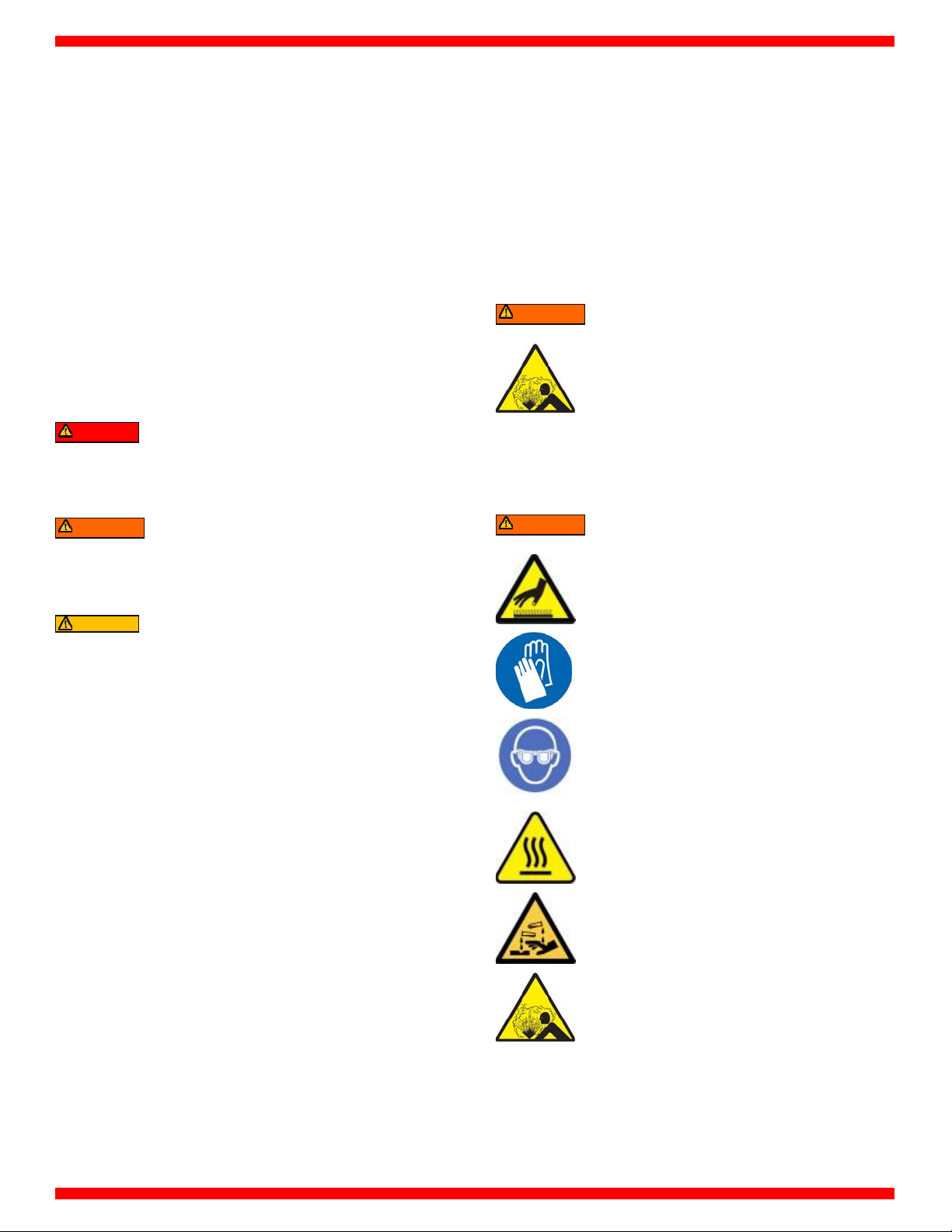
EXPLOSION HAZARDS
Warning
Risk of explosion
Do not fill the tank to more than 80% of the
maximum capacity.
Explosion can cause death or personal injury.
HEAT/FREEZING HAZARDS
Warning
Risk of personal injury
Handle refrigerants and pressure vessles
with caution.
Wear safety glasses, gloves, and suitable
clothing.
Avoid contact with the skin.
Avoid breathing A/C refrigerant and
lubricant vapor mist.
Contact with refrigerant can cause health risks,
blindness, and other physical damage (frostbite) and
possibly death.
Risk of personal injury and equipment damage
Always use an identifier before recovering
refrigerent from a vehicle.
Recover only the refrigerent the product
was certified to be used with.
Recovery of refrigerents other than the one the unit
was certified for may cause injury, equipment
damage and possible death. Alternate refrigerants
may contain flammables such as butane or propane
and can explode or cause a fire.
Published standards on safety are available and are listed at the
end of this section under ADDITIONAL SAFETY INFORMATION.
The National Electrical Code, Occupational Safety and Health Act
regulations, local industrial codes and local inspection
• 5 •
Page 6
y
v
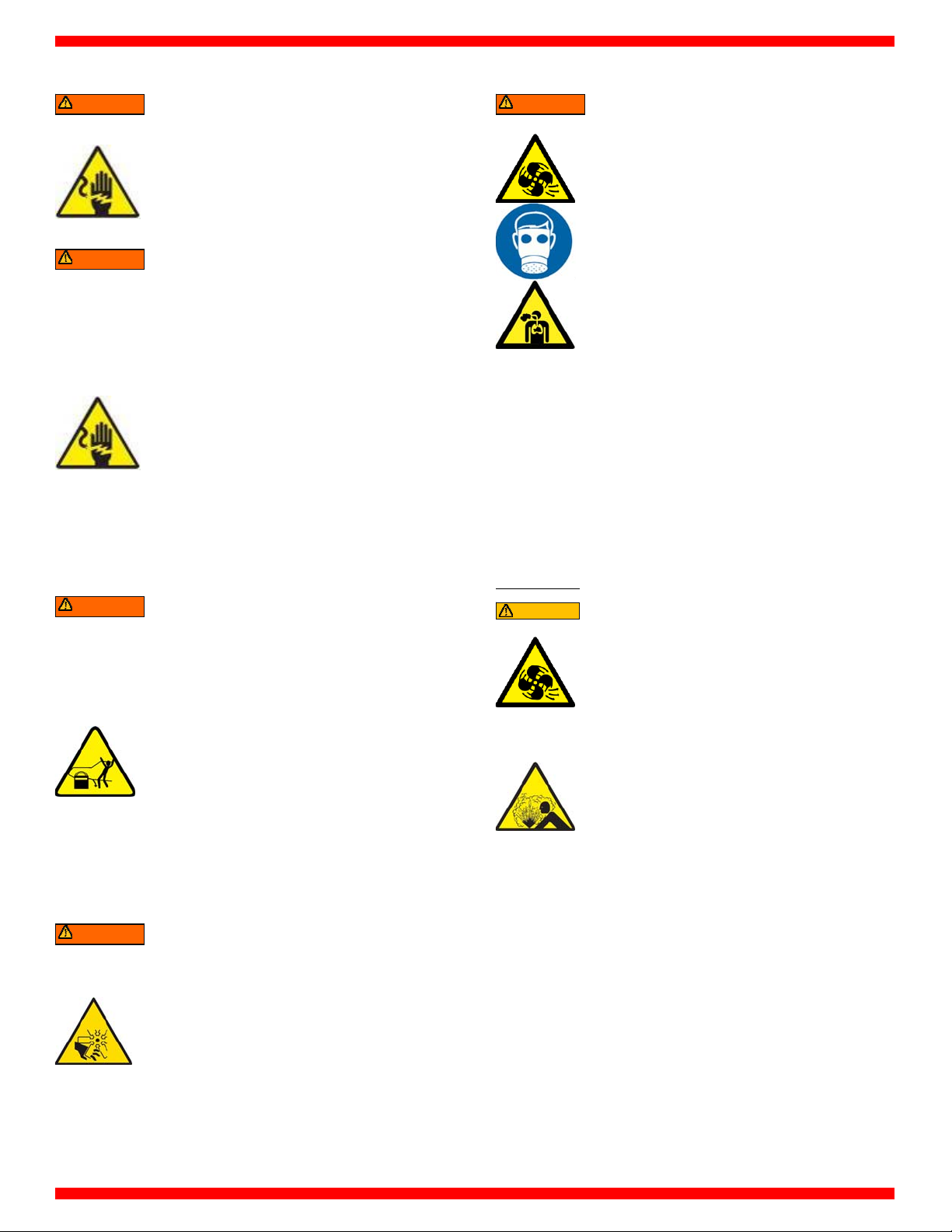
GENERAL SAFETY MESSAGES
Warning
Warning
Warning
Warning
Risk of electric shock
Unplug unit before attempting any
maintenance or cleaning.
Do not operate unit with damaged cord or
plug.
Electric shock can cause injury or death.
Risk of equipment or circuit damage
Always unplug equipment from electrical
outlet when not in use.
Never use the cord to pull plug from an
outlet. Grasp the plug and pull it to
disconnect.
If an extension cord is necessary, a cord with
a current rating equal to or more than the
equipment should be used. Cords rated for
less current may overheat.
DO NOT adapt your unit for a different
refrigerant — system failure will result.
R134a systems have special fittings (per SAE
specifications) to avoid cross contamination.
Improper use of equipment can cause equipment or
circuit damage.
Risk of unexpected vehicle movement
Block drive wheels with chocks before
performing a test with engine running.
Unless instructed otherwise, set parking
brake, and put gear selector in neutral or
park.
If the vehicle has an automatic parking
brake release, disconnect the release
mechanism for testing and reconnect when
finished.
Do not allow bystanders to stand in front of
or behind the vehicle while testing.
Do not leave a running engine unattended.
A moving vehicle can cause death or serious injury.
Risk of personal injur
Keep yourself, clothing and other objects
clear of hot or moving parts.
Keep hoses and cords clear of moving parts.
Do not wear watches, rings, or loose
clothing when working in an engine
compartment.
Contact with hot or moving parts can cause injury.
FUME HAZARDS
Warning
Risk of fume, gas, and vapor hazards
Avoid breathing A/C refrigerant and
lubricant vapor mist.
Always perform vehicle service in a properly
ventilated area.
Never run an engine without proper
ventilation for its exhaust.
Fume, gas, and vapors can cause irritation to eyes,
nose, and throat, cause illness or death.
ADDITIONAL SAFETY INFORMATION
For additional information concerning safety, refer to the
following standards.
ANSI Standard Z87.1 — SAFE PRACTICE FOR OCCUPATION AND
EDUCATIONAL EYE AND FACE PROTECTION - obtainable from
the American National Standards Institute, 11 West 42nd St., New
York, NY 10036, Telephone (212) 642-4900, Fax (212) 398-0023 www.ansi.org
Caution
NOTE: Use only new lubricant to replace the amount
removed during the recycling process. Used lubricant
should be discarded per applicable federal, state, and local
requirements.
The manufacturer shall not be responsible for any additional
costs associated with a product failure including, but not
limited to, loss of work time, loss of refrigerant, cross
contamination of refrigerant, and unauthorized shipping
and/or labor charges.
Risk of
Must have at least four air changes per hour
Poor ventilation can cause irritation to eyes, nose,
and throat, illness, or death.
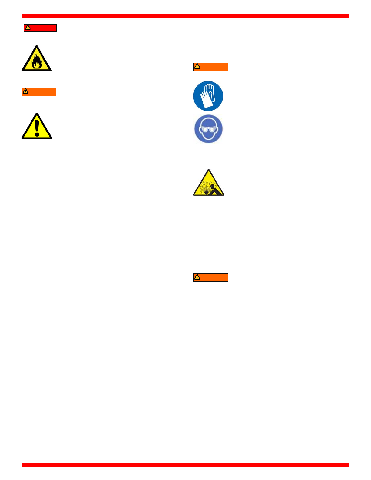
Risk of explosion
Do not pressure test or leak test R134a
Explosion can cause injury or death.
entilation hazards
or equipment should be located at least 18”
(457 mm) above the floor.
equipment and/or vehicle air conditioning
systems with compressed air.
• 6 •
Page 7
y
y
Danger
Warning
Risk of explosion
Ensure that you are only recovering from the
fitting on the AC system.
Some car manufacturers on the fuel intake
manifold install a connector identical to the
A/C low pressure fitting.
Explosion can cause injury or death.
Risk of personal injur
Do not operate equipment with damaged
cord or hoses.
Do not operate the unit if it has been
damaged until it has been examined by a
qualified service personnel.
Damaged parts can cause injury or death.
HOSES CONNECTION
Hoses may contain refrigerant under pressure. Before
disconnecting the quick coupler verify the corresponding
pressure in the service hoses (gauge).
SAFETY DEVICES
REFRIGERANT AND LUBRICANT PERSONAL PROTECTIVE EQUIPMENT
AND PRECAUTIONS
Warning
Risk of personal injur
Handle refrigerants and pressure vessles
with caution.
Wear safety glasses, gloves, and suitable
clothing.
Avoid contact with the skin.
Contact with refrigerant can cause health risks,
blindness, and other physical damage (frostbite).
Risk of equipment damage and personal injury
Should be operated by certified personnel.
Do not remove the seals of the safety valves
and control systems.
Do not use external tanks or other storage
containers that are not approved.
Do not block air vents and ventilation
equipment.
Improper use of equipment can cause equipment
damage and personal injury.
The machine is equipped with the following safety devices:
SAFETY PRESSURE SWITCH: Stops the compressor in case of
excessive pressure.
SAFETY VALVE: Opens when the pressure inside the system
reaches a level of pressure above the estimated limits.
MAIN SWITCH: Connects and disconnects machine AC electrical
power. Disconnect main power cord from electrical power
sourcebefore servicing.
ANY KIND OF TAMPERING OF THE SAFETY DEVICES
MENTIONED ABOVE IS NOT ALLOWED.
PRECAUTIONS FOR HANDLING AND USE
OF R134a FLUIDS
Warning
Risk of personal injury. Risk for handling pressurized R134a
containers
Avoid inhaling highly concentrated vapors.
Avoid use of R134a near open flames and incandescent
elements.
Wear protective garments such as to ensure that no jets
of liquid or gas can come into contact with the skin.
Wear goggles to avoid contact with the eyes.
Avoid dispersing the R134a refrigerant fluid utilized in the
machine into the atmosphere.
Mishandling of pressurized R134a containers can cause loss of
Consciousness, injury or death.
• 7 •
Page 8
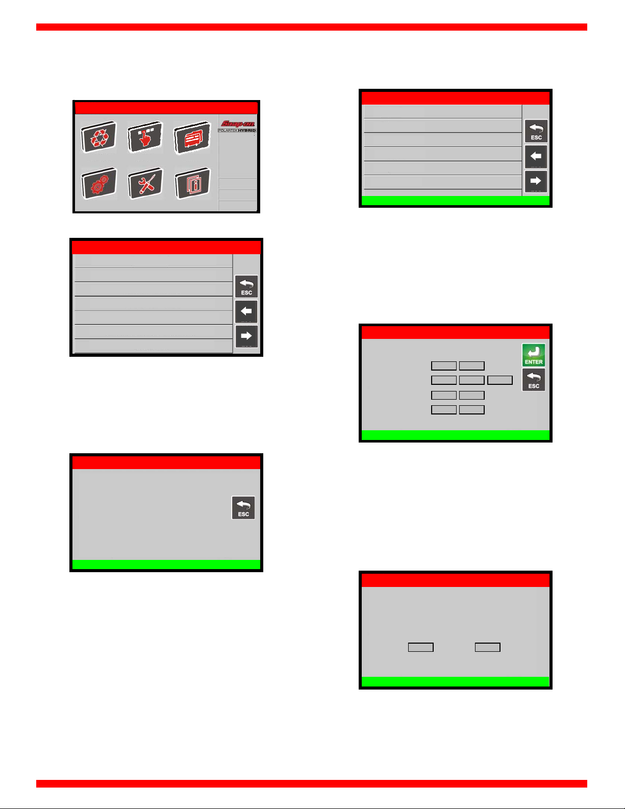
SETUP
From the MAIN MENU:
R134a
AUTOMATIC MANUAL SERVICES
xxxxxxx
hh:mm
SETUP MAINTENANCE INFO
Select the SETUP, the following screen will be displayed:
R134a SETUP
COUNTERS
LANGUAGE
MEASURE UNITS
PLATE NUMBER
QUICKSETUP
SET DATE / TIME
SETUP HEADER PRINT
COUNTERS
mm/dd/yyyy
PREV
PAGE
NEXT
PAGE
LANGUAGE
From the SETUP, select LANGUAGE :
R134a SETUP
English
Français
Espanol
LANGUAGE
PREV
PAGE
NEXT
PAGE
NOTE: Current language is indicated by red dot.
Select a language, the unit will change the language in few
seconds.
MEASURE UNITS
From the SETUP MENU, select MEASURE UNITS, the following
screen is displayed:
R134a SETUP
Pressure
Weight
Temperature
Volume
SETTINGS
bar psi
g lb lb: oz
°C °F
ml oz
From the SETUP MENU, select COUNTERS, the following screen is
displayed:
R134a SETUP
Recovered gas xxx lb
Service xxx lb
Filter xx %
Vacuum xxx min
Charged gas xxx lb
Tank filling xx lb
COUNTERS
This screen displays the total values for: gas recovered, service
alarm counters, filter status, total vacuum time (minutes), gas
injected, and gas recovered in the internal tank using the “Tank
filling” function.
MEASURE UNITS
Select the unit of measurement to change, then select between
international system of units (SI) and imperial system units (IMP).
When finished press ENTER to exit. The machine will reboot to
update measure units.
PLATE NUMBER
From the SETUP MENU, select PLATE NUMBER, the following
screen is displayed:
R134a SETUP
ACTIVATE PLATE NUMBER
ON OFF
Select ON to visualize insert plate screen during automatic or
manual procedures, or OFF to skip this screen.
PLATE NUMBER
• 8 •
Page 9
V
QUICKSETUP
The first time the machine is used, a quick startup guide appears:
the operator is guided through the steps described at the start of
the PRELIMINARY OPERATIONS section. From the SETUP MENU,
select QUICKSETUP, the following screen is displayed:
R134a SETUP
Welcome to POLARTEK Quick Setup
Press ENTER to proceed
Press ENTER to proceed with QUICKSETUP, the user will be
guided throught the following steps:
Language selection
Measure units selection
License plate recording
Date and time selection
Setup header print
Vacuum settings
Leak check test
Tank filling
Press ESC to exit.
QUICKSETUP
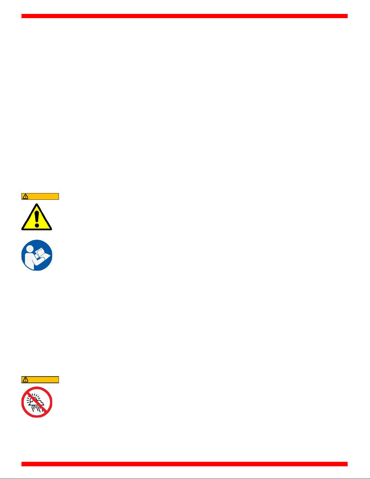
SETUP HEADER PRINT
The printout can be personalized by entering 4 lines containing
the workshop’s details (e.g. name, address, telephone number
and e-mail).
From the SETUP, select SETUP HEADER PRINT:
R134a SETUP
SETUP HEADER PRINT
Use the keypad to modify the 4 lines, then press ENTER to return
to SETUP menu.
NOTE: the numerical keys include an alphabet that is used
similar to text messaging; for example: press “2” once to display
“2”, twice to display “A”, three times for “B”, four times for “C”, five
times for “a”, six times for “b”, seven times for “c”, eight times for
“2” again.
Follow the instructions displayed. At the end of the procedure,
press ENTER to print a summary report of the guided procedure.
Press ESC to exit.
NOTE: If the guided procedure is not completed, it will be
displayed again the next time the machine is switched on.
NOTE: To display the QUICKSETUP at any time, select from the
menu of the same name under SETUP.
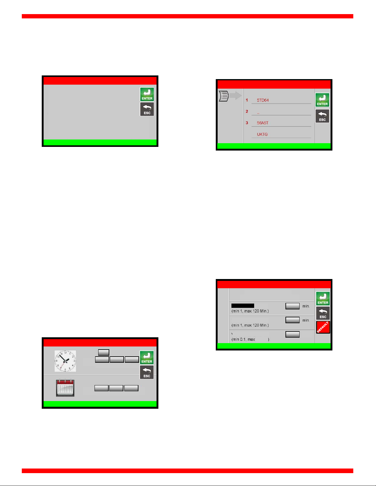
SET DATE / TIME
The machine keeps date and time settings even if it is not used
for around one year. From the SETUP MENU, select SET DATE /
TIME:
R134a SETUP
PM
Time
Date
Use keypad to change date and time. Press ENTER to confirm, or
press ESC to return to SETUP menu without saving the changes.
For example, to insert the date January 21
month then type “1” using the keypad, select the day then type
“21” using the keypad, select the year then type “2015” using the
keypad; press ENTER to confirm and exit.
xx xx xx
Hours Minutes Seconds
xx xx xxxx
Month Day Year
SET DATE / TIME
st
2015, select the
VACUUM SETTINGS
Allows to modify the default vacuum time and the default time
of check.
From the SETUP, select VACUUM SETTINGS, default setting is
displayed:
R134a SETUP
ACUUM SETTINGS
Pressing INFO set default values
Vacuum Time
Time of check
Vacuum rising
9 psi
VACUUM SETTINGS
xx
xx
xx
psi
Each value can be modified, within the values shown in
parentheses.
NOTE: Press DEFAULT to restore default values:
Vacuum time 25 min
Time of check 2 min
Vacuum rising 1 psi
• 9 •
Page 10
INTRODUCTION
ABOUT YOUR AIR CONDITIONING
SERVICE CENTER
Snap-on® Model No. EEAC332 is ETL Laboratories approved, in
compliance with SAE J2788. We are dedicated to solving the
issues surrounding the safe containment and proper
management of refrigerants. Your new machine incorporates the
latest technology and state of the art features to aid you in
servicing R134a air conditioning and refrigeration systems. We
hope you get as much enjoyment using this equipment as we
did designing and building it.
CERTIFICATION
All technicians opening the refrigeration circuit in automotive air
conditioning systems must now be certified in refrigerant
recovery and recycling procedures to be in compliance with
Section 609 of the Clean Air Act Amendments of 1990. For
information on certification call MACS Worldwide at (215) 631-
7020.
ABOUT THIS MANUAL
CAUTION
This manual includes a safety summary,
machine preparation for use, operation
procedures, and maintenance instructions, for
your Air Conditioning Service Center.
Your machine incorporates a highly accurate electronic scale for
determining charging weights, etc. Other functions can also be
performed with the electronic scale as you will discover during
the operating procedures. Either standard or metric units of
measure can be selected. This machine is a piece of equipment
designed to recover R134a from air conditioning systems (A/C)
for vehicles, to operate within the objectives of the Montreal
Protocol.
Anyone intending to use the machine should
become familiar with ALL the information
included in this manual (especially the safety
summary) before attempting to use it.
Before operating this machine for the first time, perform all
preparation for use instructions.
If your new machine is not properly prepared to perform a
service, your service data could be erroneous. In order to
properly perform a complete air conditioning service, follow all
procedures in the order presented. Please take the time to study
this manual before operating the machine. Then keep this
manual close at hand for future reference. Please pay close
attention to the safety summary and all warnings and cautions
provided throughout this manual. To activate the published
warranty, mail the attached warranty card.
CAUTION
The machine is intended for indoor use only.
• 10 •
Page 11
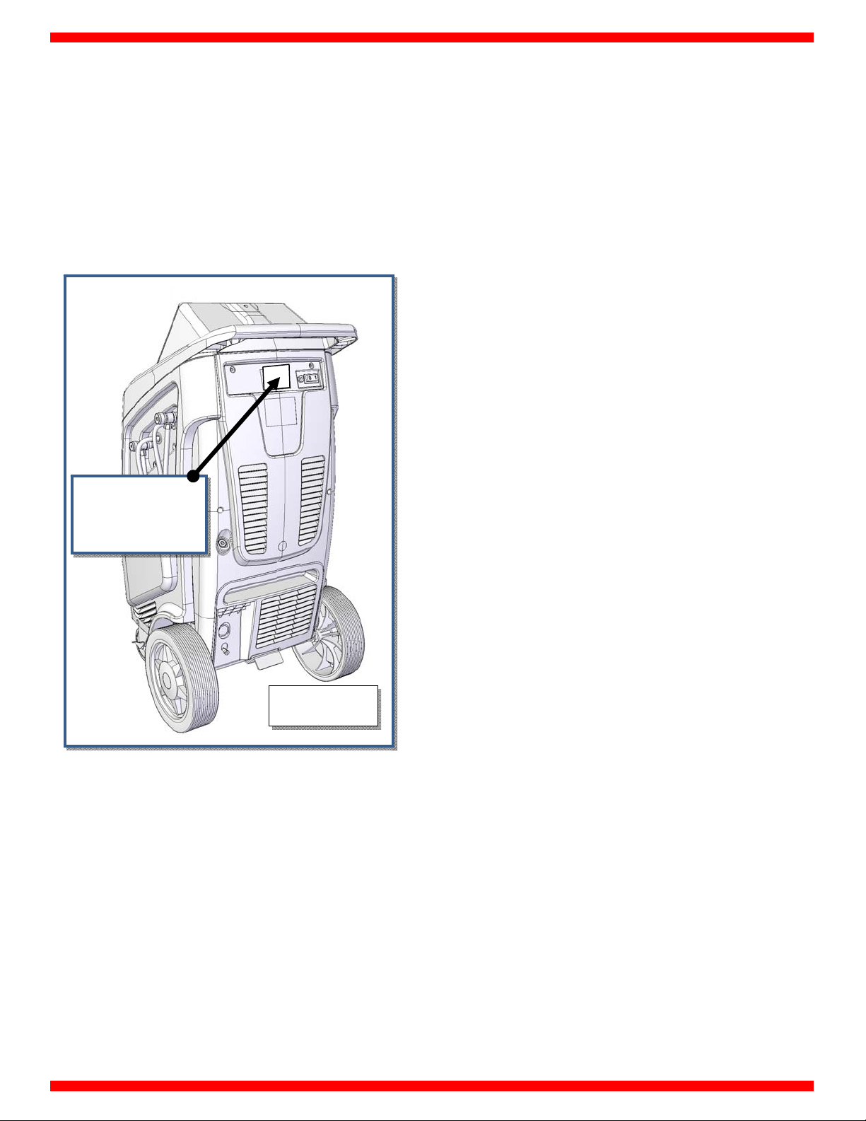
GENERAL INFORMATION
Machine model information are printed on the data plate (see
Fig. 1). Overall machine dimensions:
Height: 47" (120 cm)
Width: 25" (64 cm)
Depth: 25" (64 cm)
Weight: 200 lbs (90 kg)
Operating temperature 50/122°F (10/50°C)
Storage temperature -13/122°F (-25/50°C)
PRINCIPLES OF OPERATION
In a single series of operations, the machine permits recovering
and recycling R134a refrigerant fluids with no risk of releasing the
fluids into the environment, and also permits purging the A/C
system of humidity and deposits contained in the oil.
The machine is in fact equipped with a built-in
evaporator/separator that removes oil and other impurities from
the refrigerant fluid recovered from the A/C system and collects
them in a container for that purpose.
The fluid is then filtered and returned perfectly recycled to the
tank installed on the machine.
The machine also permits running certain operational and seal
tests on the A/C system.
NAMEPLATE
FIG. 1
Like any equipment with moving parts, the machine inevitably
produces noise. The construction system, panelling, and special
provisions adopted by the Manufacturer are such that during
work, the average noise level of the machine is not in excess of
64 dB (A).
• 11 •
Page 12

THE MACHINE
PLASTIC COVER
Refer to Fig. 4a .
1) Upper plastic body
2) Frontal body shell
Disassembly: Screw off 6 screws marked (+)
3) Right side body shell
Disassembly: Remove frontal and rear body shell, both
right doors and then screw off 8 screws marked (+)
4) Right upper door
5) Right bottom door
3
+
Refer to Fig. 4b.
6) Rear body shell
Disassembly: Remove rear bottom door, then screw off
6 screws marked (+)
7) Left side body shell
Disassembly: Remove frontal and rear body shell, then
screw off 10 screws marked (+)
+
6
+
5
FIG. 4a
+
+
+
1
+
+
FIG.4b
+
+
+
+
2
• 12 •
Page 13
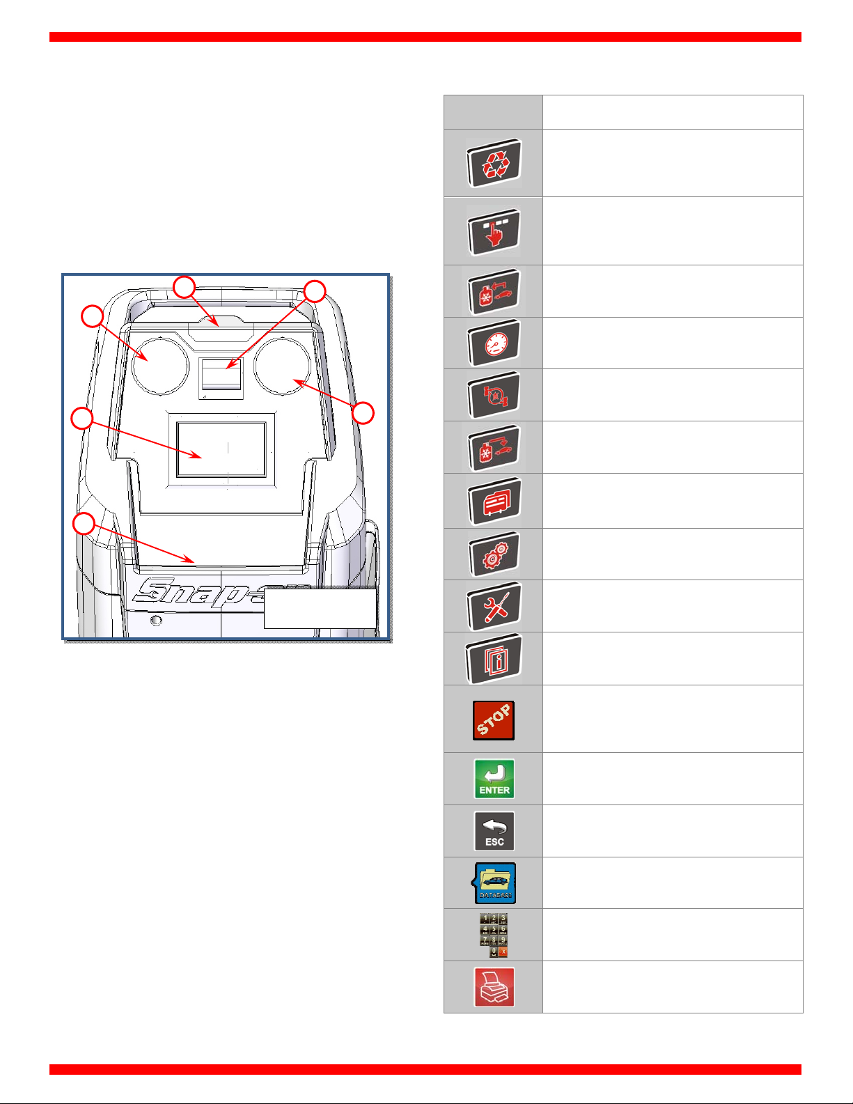
CONTROL PANEL
Refer to Fig. 5:
1) Low pressure gauge
2) High pressure gauge
3) Printer
4) 7” touch color display
5) Tool tray
6) Status light
6
1
4
3
DISPLAY ICONS
ICON DESCRIPTION
AUTOMATIC PROCEDURE: Activates a menu
that helps the user set up an automatic
recover/vacuum/leak test/charge sequence
MANUAL PROCEDURE: Activates a menu
that helps the user to perform a manual
operation
RECOVERY: Activates a menu that helps the
user to perform a recovery/recycling phase
VACUUM: Activates a menu that helps the
user to perform a vacuum phase
FLUSHING HOSES: Activates a menu that
2
helps the user to perform a flushing hoses
CHARGE: Activates a menu that helps the
user to perform a gas charge phase
5
FIG. 5
LIGHT SIGNALS
The machine is provided with a STATUS Light (ref 6, Fig. 5).
Light signals are the following:
GREEN (STEADY): Unit ready
GREEN (FLASHING): Action completed
YELLOW: Unit working
RED: Needs attention or there is a problem
SERVICES: Activates services menu
SETUP: Activates the setup menu of the
service station
MAINTENANCE: Activates the maintenance
menu of the service station
INFO: Activates a menu that contains all the
information of the service station
STOP: Terminates a procedure or operation,
silences the audible alarm or returns to the
previous screen
ENTER: Confirm a procedure or operation
shown on the display
ESC: Return back to previous menu
DATABASE: Activate database menu
KEYPAD: Numerical keypad (includes an
alphabet that is used to text messaging)
PRINTER: To print the receipt of the
procedure
• 13 •
Page 14
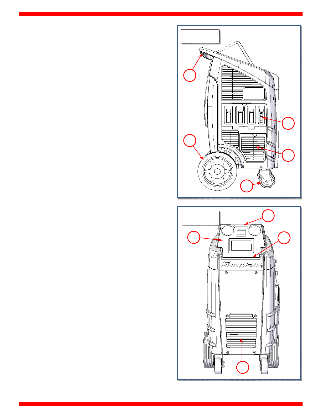
BASIC COMPONENTS
Refer to Fig. 7, Fig. 8, Fig. 9, Fig. 10:
a) Handle
b) Rear wheel
c) Front swirling wheel
d) Filter dryer panel access
e) Used oil container
f) Capsizable control panel
g) Status light
h) Tool tray
i) Ventilation grid
j) Service hoses pocket
k) Oil pump filling cap
l) Drive up pedal
m) Magnet for reference weight
n) Circuit breaker
o) Power cord exit
p) HP service hose outlet
q) HP quick connection
r) USB port
s) LP service hose outlet
t) LP quick connection
FIG.7
a
b
FIG.8
f
e
d
c
g
h
i
• 14 •
Page 15

FIG.9
j
k
FIG.10
p
q
l
o
n
m
s
r
ALARMS
HIGH PRESSURE ALARM: Beeper advises when the pressure of
the fluid in the circuit is too high 290 psi (20 bar). The recovery
operation is automatically interrupted.
FULL TANK ALARM: Beeper advises when the tank is filled to
more than 80% of maximum capacity, 24 lbs (10.9 kg). The
RECOVERY operation is automatically interrupted (to cancel this
alarm, charge one or more A/C systems before recovering any
more refrigerant).
EMPTY TANK ALARM: Beeper advises when the quantity of
refrigerant fluid contained in the tank is low, less than 3 lbs (1.36
kg).
VACUUM PUMP OIL CHANGE: Beeper advises after 15 hours of
work of the vacuum pump; change the oil of the vacuum pump.
SERVICE ALARM: Beeper advises whenever the total recovered
refrigerant amounts to 155 lbs (70 kg). To deactivate the alarm,
replace the filters and the vacuum pump oil. A code for canceling
the alarm is supplied with the spare filters.
t
• 15 •
Page 16

ERROR MESSAGES
SYSTEM LEAKS: Error message displayed when the AC system
connections are not tight.
Solution: Verify the connections between the service hoses and
quick couplers, and make another 5 min vacuum test only on
service hoses . If the problem persists, delete the residual oil in
the service hoses making a short 4 oz (100 g) charge in the
service hoses and then a recovery, and repeat the 5 minutes
vacuum test on service hoses.
NOTE: If the vacuum test on service hoses passes, means that the
A/C system has a leak which must be localized using a leak
detector.
PRESENCE OF REFRIGERANT INTO THE A/C SYSTEM:
message displayed when starting the vacuum, the charging
station checks the presence of a pressure inside the A/C system.
Solution:
LOW VACUUM:
value of the vacuum> 400mbar.
Solution:
minutes).
LOW GAS AVAILABILITY:
charge, when you select a quantity greater than the availability of
gas.
Solution:
section of the user manual.
SYSTEM EMPTY:
recovery procedure, but is not found pressure in the A/C system.
Solution: Check the connection and closing of the quick couplers.
If after all these checks, the machine continues to give the same
error, means that the A/C system is empty.
Perform a recovery procedure.
Error message displayed before charge if the
Perform a quick vacuum procedure (at least 20
Error message displayed during
Fill the inner refrigerant tank, refer to the Tank Filling
Error message appears when you select a
Error
CHECK CONNECTIONS:
rate of charge is too low.
Solution: Verify the correct opening of the quick couplers. Make
sure that the amount of gas in the refrigerant tank is > 3 lbs (1.36
kg), otherwise fill the inner refrigerant tank.
Rarely, it may happen that the temperature of the engine
compartment of the vehicle is too high compared to that of the
charging station. This can cause an immediate balance between
the refrigerant tank pressure and A/C pressure causing a
slowdown or interruption of the charge. To avoid this, it is
recommended not to fill A/C in a vehicle exposed to the sun or a
vehicle with the engine running.
EMPTY EXTERNAL TANK:
process of charge the refrigeant tank when the pressure drops to
zero before the completion of the procedure.
Solution:
the external tank; if the external tank is empty, replace it with a
full one. Then run another charge.
HIGH PRESSURE ALARM:
recovery procedure, internal tank filling, empty hoses, or flushing
hoses, this occurs when the hydraulic pressure reaches
approximately 290 psi (20 bar). The causes may be:
Ambient temperature where is located in the station is too high.
Solution:
before resuming the interrupted procedure.
Number of services performed by the station is excessive.
Solution:
before resuming the interrupted procedure.
One of the taps of the internal tank is closed.
Solution:
Check the connections, quick couplers and valves on
To wait for a sufficient time to cool the charging station
To wait for a sufficient time to cool the charging station
To open the tap and resume the interrupted procedure.
Error message displayed when the flow
Error message appears during the
Error message appears during the
SET QUANTITY LOWER THEN 4 oz (100 g):
displayed during charge when the amount of gas typed is less
than 4 oz (100 g) (both automatic and manual procedure).
Solution:
(100 g).
Set a quantity of gas greater than or equal to 4 oz
Error message
• 16 •
Page 17

PRELIMINARY OPERATIONS
Check that the main switch (ref 1, Fig. 11) is set to O. Connect the
machine to the electrical supply and switch on.
1
FIG. 11
Check that the oil level in the used oil container is < 6.8 Oz (200
cc). If necessary empty it as described in ordinary maintenance
section.
Check on the machine display that there are at roughly 4.4 lb (2
kg) of refrigerant in the tank. Should this not be the case, fill the
on-board machine tank from an external tank of appropriate
refrigerant following the procedure described in the tank filling
(maintenance menu).
Check that the vacuum pump oil level indicator (ref 3, Fig. 12)
shows at least one-half full. If the level is lower, add oil as
explained in the maintenance section.
FIG. 12
3
MAX
OPTIMAL
MIN
• 17 •
Page 18

AUTOMATIC PROCEDURE
NOTE: select value box, then use the keypad to modify
procedure parameters, press ENTER to confirm.
In the automatic mode, all the operations are performed
automatically: recovery and recycling, oil discharge, vacuum,
new oil reintegration, and charging. The values for the quantity
of gas recovered, quantity of oil recovered, vacuum time,
quantity of oil reintegrated, and quantity of gas charged into the
system are automatically printed at the end of each single
operation.
Before the automatic procedure, start the vehicle engine with
the hood closed (the air conditioner must switch OFF) for 10
minutes to warm the engine. Switch off the vehicle engine.
Connect the hoses to the A/C system with the quick-connect
couplings bearing in mind that BLUE must be connected to the
low-pressure side and RED to high pressure. If the A/C system is
equipped with a single quick-connect coupling for high or low
pressure, connect only the relative hose.
From the MAIN MENU:
R134a
AUTOMATIC MANUAL SERVICES
xxxxxxx
hh:mm
SETUP MAINTENANCE INFO
mm/dd/yyyy
Select the AUTOMATIC PROCEDURE, the following screen will be
displayed:
R134a AUTOMATIC PROCEDURE
EDIT VACUUM DATA
Select VACUUM TIME value box. Use the KEYPAD to insert the
new value of the VACUUM TIME. Press ENTER to confirm, ESC to
return back.
NOTE: Use the VACUUM SETTING to change the duration of the
TIME OF CHECK.
NOTE: If selected VACUUM TIME is lower than 15 minutes the
following popup warning will be displayed:
R134a AUTOMATIC PROCEDURE
The selected vacuum time is lower than
15 minutes. The leak check could not be
reliable. Continue?
YES
VACUUM
NO
Press YES to continue, or press NO to go back.
EDIT CHARGE AMOUNT DATA
NOTE: For most systems the quantity of fluid to be refilled is
indicated on a plate that is in the vehicle’s engine compartment.
If this quantity is not known, look for it in the relevant manuals.
Select CHARGE AMOUNT value box, then use the keys 0 to 9 to
type the quantity of refrigerant to be charged into the A/C
system.
NOTE: If DATABASE is installed, it can be used to insert the value
of refrigerant into the CHARGE field.
The use of PAG OIL
or DYE in hybrid
cars may damage
compressor!
Please use only
recommended oil.
Standard vehicle
Hybrid vehicle
NOTE: If charge amount is lower than 4 oz (100 g) the following
popup warning will be displayed:
R134a AUTOMATIC PROCEDURE
If HYBRID VEHICLE is selected the machine will perform
FLUSHING HOSES (Refer to Manual Procedure section, pg 24,
FLUSHING HOSES), then the following screen will be displayed:
R134a AUTOMATIC PROCEDURE
VACUUM TIME 1 min
TIME OF CHECK xx min
g
CHARGE AMOUNT
lb
lb/oz
xx
xx
HP+LP LP HP
lb
DATABASE
NOTE: press g, lb, or lb/oz to change the weight measurement
units.
Charge amount lower than 4 oz (100 g) is not allowed, press
ENTER then re-enter a higher CHARGE AMOUNT value.
EDIT CHARGE MODE
Select the connection mode:
HP+LP fill the refrigerant from both HP and LP service
ports.
WARNING !
charge amount
Less than 100g/4oz
Press ENTER to continue
CHARGE
HP to fill the refrigerant only from the HP service port.
• 18 •
Page 19

A
LP to fill the refrigerant only from the LP service port.
START AUTOMATIC PROCEDURE
After selected all the procedure data, press ENTER to continue. If
plate number is enabled, the following screen will be displayed:
R134a AUTOMATIC PROCEDURE
2
3
ABC
DEF
5
6
JKL
MNO
8
9
TUV
WXYZ
0
← .,
|_|
RECOVERY / RECYCLE
___________________
GHI
PQRS
1
4
7
Type the plate of the car, press ENTER to confirm. ESC to return
back.
NOTE: the numerical keys include an alphabet that is used
similar to text messaging; for example: press “2” once to display
“2”, twice to display “A”, three times for “B”, four times for “C”, five
times for “a”, six times for “b”, seven times for “c”, eight times for
“2” again.
Inset vehicle
Plate number:
R134a AUTOMATIC PROCEDURE
GAS EXTRACTION FROM A/C SYSTEM 1st PHASE
Recovered gas
Tank Pressure
/C pressure
Tank temperature
RECOVERY / RECYCLE
lb
psi
psi
°F
During the recovery phase, the machine displays the quantity of
refrigerant recovered. Upon completion of recovery, the
machine will stop and discharge, while automatically displaying
the used oil extracted from the A/C system during the recovery
phase.
The oil discharge operation lasts 4 minutes.
R134a AUTOMATIC PROCEDURE
lb
psi
oz
Then SUMMARY SCREEN will be displayed:
R134a AUTOMATIC PROCEDURE
VACUUM TIME
CHARGE AMOUNT
CONNECTION MODE HP+LP
VEHICLE PLATE UHU2445RF
Press ENTER to continue, ESC to go back
min
lb
Press ENTER to confirm the displayed values and start the
procedure. ESC to return back.
The following screen will be displayed:
R134a AUTOMATIC PROCEDURE
Connect and open HP and LP coupling to A/C
system Press ENTER
RECOVERY / RECYCLING
Connect and open the coupling to the A/C system, then press
ENTER. Press ESC to return back.
The AUTOMATIC PROCEDURE will start, and the following screen
will be displayed:
RECOVERY / RECYCLE
Completed the recovery phase, the machine automatically goes
on to running the vacuum phase for the preset time:
R134a AUTOMATIC PROCEDURE
A/C Pressure
inHg
VACUUM
At the end of this phase, the machine will test for leaks in the A/C
system:
R134a AUTOMATIC PROCEDURE
A/C Pressure
inHg
CHECK LEAKS
VACUUM
(WARNING! If vacuum time < 15 minutes this test is not reliable).
If leaks are found, the machine will stop automatically and
display the A/C SYSTEM LEAKS alarm.
Detection of micro-leaks is not guaranteed.
NOTE: The air purge is made automatically during the vacuum
phase, or when the machine is in stand by for 3 minutes always
automatically.
• 19 •
Page 20

A
However air purge can always be made at any time manually by
the AIR PURGE MANUAL selection from MAINTENANCE menu.
Upon completion of the vacuum phase, the system will go on to
charging with the preset quantity of refrigerant.
R134a AUTOMATIC PROCEDURE
Gas charged
Tank Pressure
/C pressure
Tank temperature
CHARGE
lb
psi
psi
°F
Then the following screen will be displayed:
R134a AUTOMATIC PROCEDURE
Disconnect HP coupling Start A/C system with LP
coupling connected and press ENTER
R134a AUTOMATIC PROCEDURE
End Of Procedure
Gas recovered xxx lb
Oil discharged xxx oz
Vacuum time xxx min
Gas charged xxx lb
Press ENTER to continue
EMPTY HOSES
Procedure is now successfully completed.
Press PRINTER to print the receipt of the procedure. Press ENTER
to exit.
NOTE: The automatic procedure may be run even if the A/C
system is empty. In this case, the machine will begin with the
vacuum phase.
CHARGE
Disconnect HP coupling, Start A/C system with LP coupling
connected, press ENTER.
The A/C system will recover the refrigerant into the service hoses,
then the following screen will be displayed:
R134a AUTOMATIC PROCEDURE
Disconnect LP coupling, from A/C system and
Press ENTER
CHARGE
Disconnect LP coupling from A/C system, then press ENTER to
continue:
R134a AUTOMATIC PROCEDURE
Empty hoses
Hoses pressure
xx psi
EMPTY HOSES
The machine will recover the residual refrigerant into the service
hoses, then the following screen will be displayed:
• 20 •
Page 21

A
MANUAL PROCEDURE
In the MANUAL PROCEDURE, all the operations can be
performed individually with the exception of the
recovery/recycling phase, which is automatically followed by
used oil discharge.
The values for the quantity of gas recovered, quantity of oil
recovered, vacuum time, and quantity of gas charged into the
system are printed at the end of each single operation.
From the MAIN MENU:
R134a
AUTOMATIC MANUAL SERVICES
xxxxxxx
hh:mm
SETUP MAINTENANCE INFO
Select the MANUAL PROCEDURE, the following screen will be
displayed:
R134a MANUAL PRO CEDURE
mm/dd/yyyy
RECOVERY/RECYCLING
Before the recovery, start the vehicle engine with the hood
closed (the air conditioner must switch OFF) for 10 minutes to
warm the engine. Switch off the vehicle engine.
Connect the hoses to the A/C system with the quick-connect
couplings, bearing in mind that BLUE must be connected to the
low-pressure side and RED to high pressure.
If the A/C system is equipped with a single quick-connect
coupling for high or low pressure, connect only the relative hose.
From MANUAL PROCEDURE, select RECOVERY/ RECYCLING, the
following screen will be displayed:
R134a MANUAL PROCEDURE
2
3
ABC
DEF
5
6
JKL
MNO
8
9
TUV
WXYZ
0
←.,
|_|
RECOVERY / RECYCLE
___________________
GHI
PQRS
1
4
7
Type the plate of the car, press ENTER to confirm. ESC to return
back.
Inset vehicle
Plate number:
RECOVERY & REC.
VACUMM
FLUSHING HOSES CHARGE
NOTE: the numerical keys include an alphabet that is used
similar to text messaging; for example: press “2” once to display
“2”, twice to display “A”, three times for “B”, four times for “C”, five
times for “a”, six times for “b”, seven times for “c”, eight times for
“2” again.
The following screen will be displayed:
R134a MANUAL PRO CEDURE
Connect and open HP and LP coupling to A/C
system Press ENTER
RECOVERY / RECYCLING
Connect and open the coupling to the A/C system, then press
ENTER. Press ESC to return back.
The following screen will be displayed:
R134a MANUAL PRO CEDURE
GAS EXTRACTION FROM A/C SYSTEM 1st PHASE
Recovered gas
Tank Pressure
/C pressure
Tank temperature
lb
psi
psi
°F
RECOVERY / RECYCLE
• 21 •
Page 22

During the recovery phase, the machine displays the quantity of
refrigerant recovered.
VACUUM
Upon completion of recovery, the machine will stop and
discharge, while automatically displaying the used oil extracted
from the A/C system during the recovery phase. The oil discharge
operation lasts 4 minutes.
R134a MANUAL PROCEDURE
lb
psi
oz
RECOVERY / RECYCLE
The machine checks whether or not there is air in the tank and, if
necessary, purges the non-condensable gas. The machine will
automatically discharge any non-condensable gas.
Allowing the machine to fully complete the procedure will
reduce the risk of return flows, which may cause excessive noncondensable gas to be recharged into the air conditioning
system. If any residual refrigerant in the A/C system should
increase in pressure during this phase, the machine will
automatically begin recovering the refrigerant.
Then the machine sounds an alarm while the following screen is
be displayed:
R134a MANUAL PRO CEDURE
Close and disconnect HP and LP coupling from A/C
system and Press ENTER
Use the quick-connect couplings to connect the hoses to the A/C
system, bearing in mind that BLUE must be connected to the low
pressure side and RED to high pressure. If the system is equipped
with a single quick-connect coupling for high or low pressure,
connect only the relative hose.
From the MANUAL PROCEDURE, select VACUUM, the following
screen will be displayed:
R134a MANUAL PRO CEDURE
VACUUM TIME
TIME OF CHECK
xx
Select VACUUM TIME value box. Use the KEYPAD to insert the
new value of the VACUUM TIME. Press ENTER to confirm. ESC to
return back.
NOTE: Use the VACUUM SETTING to change the duration of the
TIME OF CHECK.
NOTE: If selected VACUUM TIME is lower than 15 minutes the
following popup warning will be displayed:
R134a MANUAL PR OCEDURE
RECOVERY / RECYCLE
Close and disconnect HP and LP coupling from A/C system, then
press ENTER , the following screen will be displayed:
R134a MANUAL PRO CEDURE
End Of Procedure
Gas recovered xxx lb
Oil discharged xxx oz
Press ENTER to continue
RECOVERY / RECYCLE
Procedure is now successfully completed.
Press PRINTER to print the receipt of the procedure. Press ENTER
to exit.
The selected vacuum time is lower than
15 minutes. The leak check could not be
reliable. Continue?
YES
VACUUM
NO
Press YES to continue, or press NO to go back.
R134a MANUAL PROCEDURE
GHI
PQRS
ABC
JKL
TUV
2
3
DEF
5
6
MNO
8
0
|_|
___________________
9
WXYZ
←.,
1
4
7
Inset vehicle
Plate number:
VACUUM
Type the plate of the car, press ENTER to confirm. ESC to return
back.
NOTE: the numerical keys include an alphabet that is used
similar to text messaging; for example: press “2” once to display
“2”, twice to display “A”, three times for “B”, four times for “C”, five
times for “a”, six times for “b”, seven times for “c”, eight times for
“2” again.
• 22 •
Page 23

R134a MANUAL PRO CEDURE
Connect and open HP and LP coupling to A/C
system Press ENTER
VACUUM
Connect and open the coupling connected to the A/C system,
then press ENTER to start the vacuum phase. Press ESC to return
back.
R134a MANUAL PRO CEDURE
A/C Pressure
inHg
R134a MANUAL PROCEDURE
End Of Procedure
Vacuum time xxx min
Press ENTER to continue
VACUUM
Procedure is now successfully completed.
Press PRINTER to print the receipt of the procedure. Press ENTER
to exit.
VACUUM
When time of check is reached, the machine will test for leaks in
the A/C system:
R134a MANUAL PR OCEDURE
A/C Pressure
inHg
LEAK CHECK
VACUUM
(WARNING! If vacuum time is lower than 15 minutes this test is
not reliable). If leaks are found, the machine will stop
automatically and display the A/C SYSTEM LEAKS alarm.
Detection of micro-leaks is not guaranteed.
At the end of the preset vacuum time, the machine will sound an
alarm and the following screen will be displayed:
R134a MANUAL PRO CEDURE
Close and disconnect HP and LP coupling from A/C
system and Press ENTER
VACUUM
Close and disconnect HP and LP coupling from A/C system, then
press ENTER , the following screen will be displayed:
• 23 •
Page 24

A
FLUSHING HOSES
This operation makes the machine suitable for a service on
vehicles equipped with electrically driven compressors (hybrid
vehicles).
From the MANUAL PROCEDURE, select FLUSHING HOSES, the
following screen will be displayed:
R134a MANUAL PROCEDURE
Connect and open HP
and LP coupling as
shown on the display.
Press ENTER
FLUSHING HOSES
Connect and open the HP and LP couplers to the respective
fitting on the machine, the press ENTER to continue:
R134a MANUAL PRO CEDURE
Check connection leaks
Hoses pressure -x.x psi
FLUSHING HOSES
After checking connection leaks, the following screen will be
displayed:
R134a MANUAL PRO CEDURE
FLUSHING HOSES
CYCLE N. 1/4
/C Pressure
Recovered oil
xxx psi
xxx oz
CHARGE
From the MANUAL PROCEDURE, select CHARGE, the following
screen will be displayed:
R134a MANUAL PR OCEDURE
The use of PAG OIL
or DYE in hybrid
cars may damage
compressor!
Please use only
recommended oil.
If HYBRID VEHICLE is selected the machine will perform
FLUSHING HOSES (Refer to Manual Procedure section, pg 24,
FLUSHING HOSES), then the following screen will be displayed:
R134a MANUAL PROCEDURE
g
CHARGE AMOUNT
lb
lb/oz
NOTE: press g, lb, or lb/oz to change the weight measurement
units.
EDIT CHARGE DATA
NOTE: For most systems the quantity of fluid to be refilled is
indicated on a plate that is in the vehicle’s engine compartment.
If this quantity is not known, look for it in the relevant manuals.
Select CHARGE value box, then use the keys 0 to 9 to type the of
refrigerant to be charged into the A/C system.
Standard vehicle
Hybrid vehicle
lb
xx
DATABASE
HP+LP LP HP
NOTE: If DATABASE is installed, it can be used to insert the value
of refrigerant into the CHARGE field.
FLUSHING HOSES
Flushing hoses lasts few minutes, then the machine will sound
and alarm and the following screen will be displayed:
R134a MANUAL PRO CEDURE
FLUSHING HOSES
Operation completed
Close and disconnect
HP and LP coupling
Press ENTER
FLUSHING HOSES
NOTE: If charge amount is lower than 4 oz (100 g) the following
popup warning will be displayed:
R134a MANUAL PR OCEDURE
WARNING !
charge amount
Less than 100g/4oz
Press ENTER to continue
CHARGE
Charge amount lower than 4 oz (100 g) is not allowed, press
ENTER then re-enter a higher CHARGE AMOUNT value.
Disconnect coupling, then press ENTER to return to the MAIN
MENU; FLUSHING HOSES is now successfully completed.
• 24 •
Page 25

EDIT CHARGE MODE
A
Select the connection mode:
HP+LP fill the refrigerant from both HP and LP service
ports.
HP to fill the refrigerant only from the HP service port.
R134a MANUAL PRO CEDURE
Disconnect HP coupling Start A/C system with LP
coupling connected and press ENTER
LP to fill the refrigerant only from the LP service port.
START PROCEDURE
After all CHARGE data is selected, press ENTER to continue, the
following screen will be displayed:
R134a MANUAL PRO CEDURE
ABC
JKL
TUV
2
3
DEF
5
6
MNO
8
0
|_|
___________________
9
WXYZ
← .,
GHI
PQRS
1
4
7
Type the plate of the car, press ENTER to confirm. ESC to return
back.
NOTE: the numerical keys include an alphabet that is used
similar to text messaging; for example: press “2” once to display
“2”, twice to display “A”, three times for “B”, four times for “C”, five
times for “a”, six times for “b”, seven times for “c”, eight times for
“2” again.
R134a MANUAL PRO CEDURE
Connect and open HP and LP coupling to A/C
system Press ENTER
Inset vehicle
Plate number:
CHARGE
CHARGE
Disconnect HP coupling. Start A/C system with LP coupling
connected, press ENTER.
The A/C system will recover the refrigerant into the service hoses,
then the following screen will be displayed:
R134a MANUAL PRO CEDURE
Disconnect LP coupling, from A/C system and
Press ENTER
CHARGE
Disconnect LP coupling, then press ENTER to continue:
R134a MANUAL PROCEDURE
Empty hoses
Hoses pressure
xx psi
EMPTY HOSES
The machine will recover the residual refrigerant into the service
hoses, then the following screen will be displayed:
R134a MANUAL PROCEDURE
CHARGE
Connect and open the coupling (HP, LP, or HP/LP, depend of the
previous choice) connected to the A/C system, then press ENTER.
Press ESC to return back.
The machine will start the charge with the preset quantity of
refrigerant.
R134a MANUAL PROCEDURE
End Of Procedure
gas charged xxx lb
Press ENTER to continue
EMPTY HOSES
EMPTY HOSES
Procedure is now successfully completed.
Gas charged
Tank Pressure
/C pressure
Tank temperature
CHARGE
lb
psi
psi
°F
Press PRINTER to print the receipt of the procedure. Press ENTER
to exit.
Then the following screen will be displayed:
• 25 •
Page 26

SERVICES
The machine keeps track of the operations done on refrigerant
fluid: recovery, system refilling, inner bottle filling. For any
operation, a record is made with date, time, type of operation,
quantities involved, plate number, inner bottle refrigerant fluid
availability. From the MAIN MENU:
R134a
AUTOMATIC MANUAL SERVICES
xxxxxxx
hh:mm
SETUP MAINTENANCE INFO
Select the MANUAL PROCEDURE, the following screen will be
displayed:
R134a SERVICE ARCHIVE
YEAR SELECTION:
2017
● 2016
2015
2015
mm/dd/yyyy
SEARCH BY PLATE
Selecting SEARCH BY PLATE, the following screen will be
displayed:
R134a SERVICE ARCHIVE
SEARCH BY PLATE:
SEARCH BY PLATE:
INSERT
VEHICLE PLATE
Use the keypad to insert plate number to search, then press
ENTER:
R134a SERVICE ARCHIVE
Plate:
1423A2422 343
35A085 852
35A085 852
Time: Date:
17:43 31/01/2013
17:53 30/02/2014
2016
SEARCH BY
PLATE
SEARCH BY
DATE
EXTRACT
ARCHIVE
A list will be displayed. Select service for detailed info:
R134a SERVICE ARCHIVE
Plate:
Time:
Date:
Recovered gas:
Injected gas:
Recovered oil:
Injected oil:
Injected die:
Vacuum time:
Vacuum reached:
Press PRINTER to print the report of the service, or press ESC to
return to previous menu.
• 26 •
Page 27

Y
SEARCH BY DATE
Selecting SEARCH BY DATE, the following screen will be
displayed:
R134a SERVICE ARCHIVE
SEARCH BY DATE:
DA
MONTH
Insert date to search, then press ENTER:
R134a SERVICE ARCHIVE
Plate: Time: Date:
1423A2422 343
35A085 852
35A085 852
A list will be displayed. Select service for detailed info:
2016
17:43 31/01/2013
17:53 30/02/2014
EXTRACT ARCHIVE
Selecting EXTRACT ARCHIVE, the following screen will be
displayed:
R134a SERVICE ARCHIVE
Please insert USB key
and press ENTER
Insert the storage device in the USB port and press ENTER, to
save to copy a .CSV file with all the operations into the USB
storage device.
The following screen will be displayed for few seconds:
R134a SERVICE ARCHIVE
EXTRACT ARCHIVE
Extraction complete
R134a SERVICE ARCHIVE
Plate:
Time:
Date:
Recovered gas:
Injected gas:
Recovered oil:
Injected oil:
Injected die:
Vacuum time:
Vacuum reached:
Press PRINTER logo to print the report of the service, or press ESC
to return to previous menu.
Extraction is now completed. The machine will return to the
previous menu.
• 27 •
Page 28

y
MAINTENANCE
From the MAIN MENU:
R134a
AUTOMATIC MANUAL SERVICES
xxxxxxx
hh:mm
SETUP MAINTENANCE INFO
Select the MAINTENANCE, the following screen will be displayed:
R134a MAINTENANCE
A/C PRESSURE CHECK
AIR PURGE MANUAL
CALIBRATION
CHANGE DRYER FILTER
DATABASE
EMPTY HOSES
MAINTENANCE REPORT
mm/dd/yyyy
PREV
PAGE
NEXT
PAGE
A/C PRESSURES CHECK
From MAINTENANCE select A/C PRESSURES CHECK, the
following screen will be displayed:
R134a MAINTENANCE
Connect and open HP and LP coupling to A/C
system Press ENTER
A/C PRESSURES CHECK
Connect and open the coupling connected to the A/C system,
then press ENTER. Press ESC to return back; the following screen
is displayed:
R134a MAINTENANCE
Turn on A/C system and
check pressure using
HP and LP gauges
then press ENTER
A/C PRESSURES CHECK
Turn on A/C system and check pressure using HP and LP
manometers, then press ENTER:
R134a MAINTENANCE
Turn off A/C system and the
vehicle’s engine
then press ENTER
A/C PRESSURES CHECK
Turn off A/C system and the vehicle’s engine, then press ENTER:
R134a MAINTENANCE
Unscrew HP coupling without disconnect from A/C
s
stem, then press ENTER
A/C PRESSURES CHECK
Unscrew HP coupling without disconnect it from A/C system,
then press ENTER:
• 28 •
Page 29

R134a MAINTENANCE
A pop-up message is displayed asking confirmation, press YES to
continue:
R134a MAINTENANCE
Are you sure that you have unscrewed
coupling or couplings without removing them?
YES
A/C PRESSURES CHECK
NO
A pop-up message is displayed asking confirmation, press YES to
continue:
R134a MAINTENANCE
With LP coupling connected
turn on vehicle’s engine
and A/C system
then press ENTER
A/C PRESSURES CHECK
With LP coupling connected turn on the vehicle’s engine and
A/C system, then press ENTER:
R134a MAINTENANCE
START UP
Please wait…
Empty hoses
Hoses pressure
xx psi
EMPTY HOSES
The machine will recover the residual refrigerant into the service
hoses, then the following screen will be displayed:
R134a MAINTENANCE
Disconnect coupling from A/C and Press
ENTER
EMPTY HOSES
Disconnect coupling from A/C system, then press ENTER:
R134a MAINTENANCE
EMPTY HOSES – OPERATION COMPLETED
press ENTER to continue
A/C PRESSURES CHECK
The vehicle’s A/C system will recover the refrigerant from the
service hoses, then:
R134a MAINTENANCE
Turn off engine and A/C system, unscrew LP coupling
without disconnect it, then Press ENTER
A/C PRESSURES CHECK
Turn off engine and A/C system, unscrew LP coupling without
disconnect it, then press ENTER:
R134a MAINTENANCE
Are you sure that you have unscrewed
coupling or couplings without removing them?
YES
NO
EMPTY HOSES
Press ENTER to return to the MAINTENANCE MENU; A/C
PRESSURES CHECK is now successfully completed.
A/C PRESSURES CHECK
• 29 •
Page 30

AIR PURGE MANUAL
From MAINTENANCE, select AIR PURGE MANUAL, the following
screen will be displayed:
R134a MAINTENANCE
PRESS ENTER TO PURGE
Tank pressure xxx psi
Tank Temperature xxx °F
Target Pressure xxx psi
PRESS ENTER TO PURGE
AIR PURGE MANUAL
If “PRESS ENTER TO PURGE” is displayed, there is air in the tank. In
this case, press ENTER: the machine will begin discharging the air.
Press ESC to pause the Air Purging process.
NOTE: If there isn’t air into the tank, the following message is
displayed: AIR PURGE NOT NECESSARY.
Press ESC to terminate the Air Purging process, and return to the
MAINTENANCE menu.
CALIBRATION
For assistance, call the Snap-on
toll-free
Technical Support Line
800-225-5786
in the continental U.S. or Canada.
• 30 •
Page 31

CHANGE DRYER FILTER
A
A
R134a MAINTENANCE
Replace the filter whenever the machine gives the service alarm
signals the presence of humidity in the circuit.
Before performing any operation, check that the replacement
filter is the same type as these installed on the machine.
Then proceed as described below:
Wear protective gloves and glasses.
Connect the machine to the electrical supply and it turn
on.
Note the release code on the new filters.
IMPORTANT: Filter replacement must be performed as
quickly as possible in order to avoid possible contamination
by moisture in the ambient air.
NOTE: If possible, check the seal on the couplings of the new
filter, using an electronic leak tester.
From MAINTENANCE, select CHANGE DRYER FILTER, the
following warning message is visualized:
R134a MAINTENANCE
n accidental leakage of refrigerant
may cause serious damage to skin and eyes
wear protective gloves and goggles
Press ENTERto continue
Warning
CHANGE DRYER FILTER
An accidental leakage of refrigerant may cause serious damage
to skin and eyes. Wear protective gloves and goggles. Press
ENTER to continue:
R134a MAINTENANCE
Make sure that HP and LP
coupling are disconnected from
/C system or else
Press ENTERto continue
CHANGE DRYER FILTER
Make sure that HP and LP coupling are disconnected from A/C
system or else and press ENTER. Machine will check presence of
refrigerant:
Verifying gas presence in filter…
CHANGE DRYER FILTER
And if necessary will recover it
R134a MAINTENANCE
Recovering gas from filter…
CHANGE DRYER FILTER
Then the following screen is displayed:
R134a MAINTENANCE
1
4
GHI
7
PQRS
.,
.,
3
2
DEF
ABC
Reset service alarm
Enter filter code
5
6
JKL
MNO
9
8
_________________
WXYZ
TUV
0
←
|_|
CHANGE DRYER FILTER
Type the filter code and press ENTER to delete the alarm. If the
filter code is not available, call the Service Center:
R134a MAINTENANCE
Unscrew
DRYER
FILTER
Remove the dryer filter
use the special wrench
and press ENTER
CHANGE DRYER FILTER
Remove the dryer filter, use the special wrench (ref Fig. 18)
• 31 •
Page 32

FIG. 18
FIG. 19
Press ENTER to continue:
R134a MAINTENANCE
Verify that both o-rings are correctly placed into their seats
press enter
CHANGE DRYER FILTER
Take the new filter
, wet with clean POE oil both o-rings, and
verify that they are correctly placed into their slots, press ENTER:
R134a MAINTENANCE
Screw
DRYER
FILTER
Insert new dryer filter
use the special wrench
and press ENTER
CHANGE DRYER FILTER
Insert the new dryer filter, use the special wrench (ref Fig. 19),
And press ENTER:
R134a MAINTENANCE
Continue with vacuum and
CHANGE DRYER FILTER
check for leaks.
Press ENTER
Press ENTER to continue with vacuum check:
R134a MAINTENANCE
Check leaks with vacuum
CHANGE DRYER FILTER
If leaks are detected the following screen will be displayed:
R134a MAINTENANCE
VACUUM LEACKS
Check filter tightening
and Press ENTER
CHANGE DRYER FILTER
Check filter tightening and press ENTER to restart the vacuum
check.
• 32 •
Page 33

After few minutes, if no leaks are detected the following screen
will be displayed:
R134a MAINTENANCE
DATABASE
From MAINTENANCE, select DATABASE.
A list of brand of vehicle will be displayed.
Pressure check
CHANGE DRYER FILTER
If leaks are detected the following screen will be displayed:
R134a MAINTENANCE
PRESSURE LEACKS
Check filter tightening
and Press ENTER
CHANGE DRYER FILTER
Check filter tightening and press ENTER to restart the pressure
check.
If no leaks are detected the following screen will be displayed:
R134a MAINTENANCE
Select the brand of vehicle, (use the arrow keys to change page if
necessary), then select the model of vehicle.
All the information about this model is displayed:
R134a VEHICLE BRAND
VEHICLE MODEL
YEARS
GENERAL INFO
REFRIGERANT DATA
OIL DATA
Press ENTER to exit, or ESC to return back to previous screen.
EMPTY HOSES
From MAINTENANCE , select EMPTY HOSES, the following screen
will be displayed:
R134a MAINTENANCE
Internal gas removal
CHANGE DRYER FILTER
Then After few minutes:
R134a MAINTENANCE
CHANGE DRYER FILTER
OPERATION COMPLETED
CHANGE DRYER FILTER
Press ENTER
Press ENTER to return to the MAINTENANCE MENU; DRYER
FILTER CHANGE is now successfully completed.
Recovered gas
Hoses pressure
EMPTY HOSES
lb
psi
The machine will recover all the refrigerant into the service hoses;
then the machine will sound an alarm and the following screen
will be displayed:
R134a MAINTENANCE
EMPTY HOSES – OPERATION COMPLETED
Press ENTER
EMPTY HOSES
Press ENTER to return to the MAINTENANCE MENU; EMPTY
HOSES is now successfully completed.
• 33 •
Page 34

MAINTENANCE REPORT
From MAINTENANCE, select MAINTENANCE REPORT, the
following screen will be displayed:
R134a MAINTENANCE REPORT
FILTER CHANGE
mm/dd/yy xx lbs
mm/dd/yy xx lbs
mm/dd/yy xx lbs
PREV
PAGE
NEXT
PAGE
Press PRINTER to print a maintenance report:
Serial number.
Total amount of recovered refrigerant.
Total running time of the vacuum pump.
Filter change detail
SERVICES ARCHIVE
Refer to SERVICES chapter.
TANK CELL CHECK
From MAINTENANCE, select TANK CELL CHECK, the following
screen will be displayed:
R134a MAINTENANCE
TANK CELL CHECK
Don't touch the machine!
TANK CELL CHECK
Wait few seconds, paying attention not to touch the machine,
then the following screen will be displayed:
R134a MAINTENANCE
TANK CELL CHECK
Attach the reference weight
to the magnet on the rear of the
machines and Press ENTER
please wait...
TANK CELL CHECK
Attach the reference weight to the magnet on the rear of the
machines and press ENTER. The following screen will be
displayed:
R134a MAINTENANCE
TANK CELL CHECK
Don't touch the machine!
please wait...
TANK CELL CHECK
Wait few seconds, then if the tank cell is correctly calibrated the
following screen will be displayed:
R134a MAINTENANCE
TANK CELL CHECK
Press ENTER to continue
CHECK OK
TANK CELL CHECK
Press ENTER to return to MAINTENANCE MENU
• 34 •
Page 35

TANK FILLING
This operation must be performed whenever the available
refrigerant fluid in the tank is less than 6.6 lb (3 kg) and must in
any case be performed when the “empty tank” alarm is
displayed.
From MAINTENANCE, select TANK FILLING, the following screen
will be displayed:
Press ENTER to start The TANK FILLING:
R134a MAINTENANCE
Tank Pressure
Ext. Tank Pressure
lb
psi
psi
lb
R134a MAINTENANCE
connect and open LP or HP coupler to the liquid side of the
external tank and open the liquid valve, then Press ENTER
2 valve tank 1 valve tank
TANK FILLING
Procure a tank of R134a refrigerant, connect and open LP coupler
to the liquid side of the external tank and open the liquid valve,
then press ENTER.
The following screen will be displayed:
R134a MAINTENANCE
Set amount:
lb
xx
xxx lb
Min
xxx lb
MAX
TANK FILLING
Select set amount, the following screen will be displayed:
R134a MAINTENANCE
1
4
GHI
7
PQRS
.,
.,
3
2
DEF
ABC
SET AMOUNT
5
6
JKL
MNO
_________________
9
8
WXYZ
TUV
0
←
|_|
Use the keypad to insert the amount of refrigerant, then press
ENTER to continue. The following screen will be displayed:
TANK FILLING
TANK FILLING
The machine will now fill the machine tank with the preset
quantity ~ 1.1 lb (500 g). When the quantity minus 1.1 lb (500 g)
is reached, the machine will stop and display:
R134a MAINTENANCE
Close liquid valve of the external tank
Press ENTER to continue
2 valve tank 1 valve tank
TANK FILLING
Close the liquid valve of the external tank and press ENTER. The
machine will recover the residual refrigerant from the hoses, then
will display the following screen:
R134a MAINTENANCE
Close and disconnect LP or HP coupling from
external tank and Press ENTER
2 valve tank
TANK FILLING
1 valve tank
Close and disconnect LP coupling from external tank and press
ENTER.
R134a MAINTENANCE
TANK FILLING – OPERATION COMPLETED
Press ENTER
R134a MAINTENANCE
Set amount:
xxx
lb
xx
xxx lb
Min
xxx lb
MAX
Tank filling procedure successfully completed. Switch the
machine off.
NOTE: The refrigerant really filled into the internal tank can vary
by ± 1.1 lb (500 g).
TANK FILLING
NOTE: If the external tank is not supplied with a liquid side
TANK FILLING
coupling, overturn it to recover liquid refrigerant.
• 35 •
Page 36

VACUUM PUMP OIL CHANGE
From MAINTENANCE, select VACUUM PUMP OIL CHANGE, the
following screen will be displayed:
R134a MAINTENANCE
Hours remaining (hh:mm)
Do you want to change the oil?
YES NO
VACUUM PUMP OIL CHANGE
Press NO to exit or press YES to begin the VACUUM PUMP OIL
CHANGE, the following screen will be displayed:
R134a MAINTENANCE
Unscrew the fitting cap and
the drain cap then remove used oil
from vacuum pump
then press ENTER
VACUUM PUMP OIL CHANGE
Unscrew the fitting cap and drain the drain cap then remove
used oil from vacuum pump then press ENTER, the following
screen will be displayed:
XX:XX
VACUUM PUMP
Perform the operations listed below on a routine basis in order to
ensure good operation of the vacuum pump.
When replacing the pump oil, use only the oil recommended by
the manufacturer. Contact your retailer for information
concerning the correct type of oil.
The vacuum pump oil must be replaced every 15 hours of
functioning and in any case every time the refrigerant filters are
replaced.
NOTE: Alarm message is visualized, to remove alarm message
refer to VACUUM PUMP OIL CHANGE paragraph.
The oil must also be replaced whenever it changes color due to
absorption of humidity. Before beginning the oil change
procedure, procure a container of at least 17 oz (500 cc) capacity
in which to collect the used oil. The pump contains about 14.9
oz (440 cc) of oil. Use only the oils recommended by the
manufacturer (consult your retailer). The use of a nonrecommended oil may impair the proper functioning of the
pump and void the warranty.
Disconnect the machine from the main supply.
Place a container (ref 4, Fig. 23). under the drain cap (ref 2, Fig.
23).
FIG. 23
R134a MAINTENANCE
Replace drain cap, refill vacuum
pump with new oil to the center of
control glass then replace filling cap.
When done press ENTER to exit
VACUUM PUMP OIL CHANGE
Replace drain cap, refill vacuum pump with new oil to the center
of control glass then replace filling cap.
When done press ENTER to exit.
2
4
Unscrew the filling cap (ref 1, Fig. 24).
• 36 •
Page 37

1
FIG. 24
Unscrew the drain cap (ref 2, Fig. 25).
FIG. 25
2
Pour in new oil through the filling hole, using a proper funnel (ref
5, Fig. 27), until the level rises to the midpoint on the indicator
(ref 3, Fig. 27).
FIG. 27
5
3
4
Allow all the oil to run out into a disposal container (ref 4 Fig. 25),
with height < 4 in (10 cm).
Close the drain cap (ref 2, Fig. 26).
FIG. 26
2
MAX
OPTIMAL
MIN
Add oil a little at a time, waiting for the level to rise before each
successive addition, until the oil reach the optimal level on the
indicator (ref 3, Fig. 27).
Replace the filling cap (ref 1, Fig. 28) and tighten down.
1
FIG. 28
• 37 •
Page 38

EMPTYING THE USED OIL CONTAINER
Procedure:
Open the upper door on the right side (ref 4, Fig. 37).
Press quick connection button (ref 1, Fig. 37) to disconnect the
used oil container.
Lift the used oil container out of its lodging (ref n, Fig. 37) without
exerting pressure on the scale.
2
FIG. 37
n
1
4
FIG. 38
Empty the used oil into a suitable container for used oils (Fig. 39).
FIG. 39
Screw the cap back into the container.
Replace the container and hook it up to the quick connection
taking care not to exert pressure on the scale in order not to
damage it.
NOTE: In order to avoid damage to the oil scale, never exert
pressure on it either from above or from below.
Unscrew the cap (ref 2, Fig. 38) while holding the container.
• 38 •
Page 39

A
A
REPLACING THE PRINTER PAPER
Open the print cover (ref 3, Fig. 40), and replace the paper roll
with a new one.
Use only heat-sensitive paper of the type described below.
Paper width: 2.2 in (58 mm).
Maximum paper roll diameter: 1.6 in (40 mm).
3
INFO
From the MAIN MENU:
R134a
AUTOMATIC MANUAL SERVICES
xxxxxxx
hh:mm
SETUP
MAINTENANCE INFO
Select the INFO, the following screen will be displayed:
R134a INFO
Tank refrigerant
Total: xxxx lb
Available: xxxx lb
Used Oil
xx oz
mbient temperature xxx °F
Tank temperature xxx °F
Tank pressure xxx psi
/C pressure xxx psi
SW V.: Software version.
mm/dd/yyyy
FIG. 40
FIG. 40
Tank refrigerant:
Total: total amount of refrigerant in the storage
tank.
Available: quantity of refrigerant available in the
storage tank.
Used: quantity of OIL in the USED OIL container.
Ambient temperature: ambient temperature near the
service station.
Tank temperature: refrigerant storage tank temperature.
Tank pressure: refrigerant storage tank pressure.
A/C pressure: pressure in the service hoses.
Press ESC to return to MAIN MENU.
• 39 •
Page 40

WARRANTY
This product is warranted against any defect in materials and/or
construction for a period of 2 (two) years from the date of
delivery. The warranty consists of free-of-charge replacement or
repair of defective component parts or parts considered
defective by the Manufacturer. Reference to the machine serial
number must be included in any requests for spare parts. This
warranty does not cover defects arising from normal wear,
incorrect or improper installation, or phenomena not inherent to
normal use and operation of the product.
The manufacturer guarantees the perfect suitability of the
materials used for packing, in terms both of composition and
mechanical strength/resistance. The guarantee does not cover
breakdowns attributable to damage suffered during shipping or
warehousing or caused by the use of accessories not meeting
manufacturer’s specifications, or to tampering with or repair of
the product by unauthorized personnel. It is of utmost
importance that the crates containing the machine be carefully
inspected, upon delivery, in the presence of the shipping agent.
We recommend performing inspection with extreme care, since
damages to the crates due to shocks or dropping are not always
immediately visible thanks to the shock-absorbing capacity of
today’s composite packing materials. The apparent integrity of
the packing materials does not exclude possible damage to the
goods, despite the due care taken by the manufacturer in
packing them.
NOTE: Regarding the above, the Manufacturer reminds the
Customer that according to international and national laws and
regulations in force the goods are shipped at the sole risk of the
latter and, unless otherwise specified in the confirmation of order
phase, the goods are shipped uninsured. The Manufacturer
therefore declines any and all responsibility in merit of CLAIMS
for damages due to shipping, loading and unloading, and
unpacking.
The product for which repair under guarantee is requested must
be shipped to the manufacturer under the customer’s exclusive
responsibility and at the customer’s exclusive expense and risk. In
order to avoid damage during shipping for repairs, the
Manufacturer’s original packing must always be used.
The manufacturer declines any and all responsibility for damage
to vehicles on which recovery/recycling and recharging are
performed if said damage is the result of unskillful handling by
the operator or of failure to observe the basic safety rules set
forth in the instruction manual. This warranty replaces and
excludes any other warranty or guarantee that the seller is
required to provide under law or contract and defines all the
customer’s rights in regard of faults and defects and/or scarce
quality in the products as purchased.
The warranty will expire automatically at the end of the twentyfour-month period or whenever one of the following occurs:
failure to perform maintenance; use of improper maintenance
procedures; use of unsuitable lubricants and/or tracer fluids;
inept or improper use; repairs performed by unauthorized
personnel and/or with non-original spare parts; damage caused
by shocks, fires, or other accidental events.
• 40 •
Page 41

NOTES
• 41 •
Page 42

• 42 •
Page 43

• 43 •
Page 44

Made in USA
Snap-on is a trademark of Snap-on Incorporated
©2016 Snap-on Incorporated
Printed in USA
Snap-on, 2801 80th St., Kenosha, WI 53143
www.snapon.com
• 44 •
 Loading...