

Page 1

042011
25A PLASMA ARC CUTTING MACHINE
PLASMA30i
IN TRODUCTION
The PLASMA30i is an inverter current power source machine, designed for cutting
electrically conductive materials (metals and alloys) using the plasma arc procedure. The
plasma gas may be air or nitrogen. The lightweight portable inverter plasma cutter has
many features that enable the user to easily cut most all metals.
Page 2

1
Introduction............................................................................................................................... Front Cover
Table of Contents ...................................................................................................................................... 1
Safety Information ..................................................................................................................................2-3
Specifications ............................................................................................................................................ 4
Features .................................................................................................................................................... 5
Description of Equipment .......................................................................................................................6-7
Assembling the Unit/Start-up Guide .......................................................................................................... 8
Plasma Cutting .......................................................................................................................................... 9
Troubleshooting/Consumable Replacement ........................................................................................... 10
Maintenance ............................................................................................................................................ 11
Replacement Parts .................................................................................................................................. 12
Wiring Diagram........................................................................................................................................ 13
Warranty/Service and Repair .................................................................................................................. 14
TABLE OF CONTENTS
Page 3

2
MUST READ INSTRUCTIONS BEFORE USE
Read, understand and follow all safety messages
and instructions in this manual. Safety messages in
this section ofthe manual contain a signal word with
a three-part message and, in some instances, an
icon.
The signal word indicates the level of the hazard in
a situation.
DANGER
Indicates an Imminently hazardous Situation which,
if not avoided, will result in death or serious injury to
the operator or bystanders.
WARNING
Indicates a potentially hazardous situation which, if
not avoided, could result in death or serious injury
to the operator or bystanders.
CAUTION
Indicates a potentially hazardous situation which, if
not avoided, may result in moderate or minor injury
to the operator or bystanders.
IMPORTANT
Indicates a situation which, if not avoided, may
result in damage to the welding equipment.
Safety messages in this section contain three
different type styles.
• Normal type states the hazard.
• Bold type states how to avoid the hazard.
• Italic type states the possible consequences of
not avoiding the hazard.
An icon, when present, gives a graphical
description of the potential hazard.
Plasma Arc Cutting
DANGER
• Electric welding or plasma cutting cause ultra
violet rays and weld spatter
Bystanders will be exposed to ultraviolet rays
and weld spatter.
Wear welding helmet with appropriate shade
lens while using electric welders or plasma
cutters.
Do not allow bystanders while welding or
cutting.
Wear safety shield and protective clothing.
Ultraviolet rays will burn eyes; weld spatter can
cause injury.
WARNING
• Plasma cutting produces heat, sparks, hazard
of electric shock and/or hazardous vapors
Wear appropriate gloves, helmets or goggles
and other protective clothing.
Follow all instructions and safe practices while
welding or cutting.
Keep bystanders away from immediate area.
Byproducts of plasma cutting can cause burns or
other bodily injury.
SAVE THESE INSTRUCTIONS
SAFETY INFORMATIO N
Page 4

3
Risk of Electrical Shock
WARNING
• Electrical shock can result when contacting
live electrode or internal components
• Electrical shock can result from absence of
grounding prong
Do not touch electrode or internal components
without protection.
Disconnect power before servicing.
Do not remove the grounding prong in any
electrical plug.
Electrical shock can cause injury
Risk of Explosion
WARNING
• Plasma cutting causes sparks that can cause
explosion
Use caution and proper procedures when
welding.
Avoid sparks if gasoline vapor and other fuels
are present.
Electrical shock, flames and explosion can cause
serious injury
Electrical and Magnetic Fields
WARNING
• Plasma cutting may cause localized Electrical
and Magnetic Fields around cables and power
sources
• The magnetic fields created by high currents
may affect the operation of medical
equipment.
Route the electrode and work cables together.
Do not place your body between the
electrode/torch and work cables.
Never coil the electrode/torch lead around
your body.
Do not work next to welding/cutting power
source.
Electrical shock and Magnetic fields can cause
injury.
Disposal of Equipment
IMPORTANT
• Disposal of electrical equipment can be
hazardous to the environment
Contact local regulations prior to disposal
Improper disposal can cause an environmental
hazard
SAFETY INFORMATIO N cont’d
Page 5
4
This machine is a constant direct current power sour
ce,
designed for cutting electrically conductive materials (metals
and alloys) using the plasma arc procedure. The plasma
gas may be air or
nitr
ogen
EXPLANATION OF THE TECHNICAL
SPECIFICATIONS LISTED ON THE
MACHINE PLATE
EN 60974.1 The machine has been built according to
EN 50199 this European
standar
ds.
EN 50192
N°..................... Serial
number
.
Always indicate this for any request
regarding the machine.
....... Single-phase static
transformer-r
ectifier
frequency
converter
.
.................... Drooping
characteristic.
................. Suitable for plasma
cutting.
TORCH TYPE ......Type of torch that may be used with
this
machine.
U0.
PEAK ....
Secondary open-circuit voltage. Peak value.
X .....................
Percentage duty
cycle.
The duty cycle expresses the
percentage
of
10 minutes for which the machine may work
at a certain current I2 and
voltage
U2 without
overheating.
I2 ......................
Cutting
curr
ent.
U2 ....................Secondary voltage at cutting current I2.
This voltage is measured when
cutting
with the gas nozzle in contact with
the
work piece.
If this distance increases, the cutting
voltage also increases and the duty cycle
X% may drop.
U1 ....................Rated supply
voltage
1~ 50/60Hz ...... 50- or 60-Hz single-phase power
supply
.
The machine is equipped with
automatic
voltage change.
I1 Max ............. Max. absorbed current at the
correspon
ding
current I2 and voltage U2.
I1 eff ................This is the maximum value of the
actual
current absorbed, considering the
duty
cycle. This value usually corresponds
to
the
capacity of the fuse (delayed type)
to
be
used as a protection for
the equipment.
IP23 S . ............ Protection rating for the housing.
Grade 3 as the second digit means
that
this
equipment may be stored, but it is not
suitable for use outdoors in the rain, unless
it is protected.
S ...................
Suitable for working in hazardous
enviro
nments.
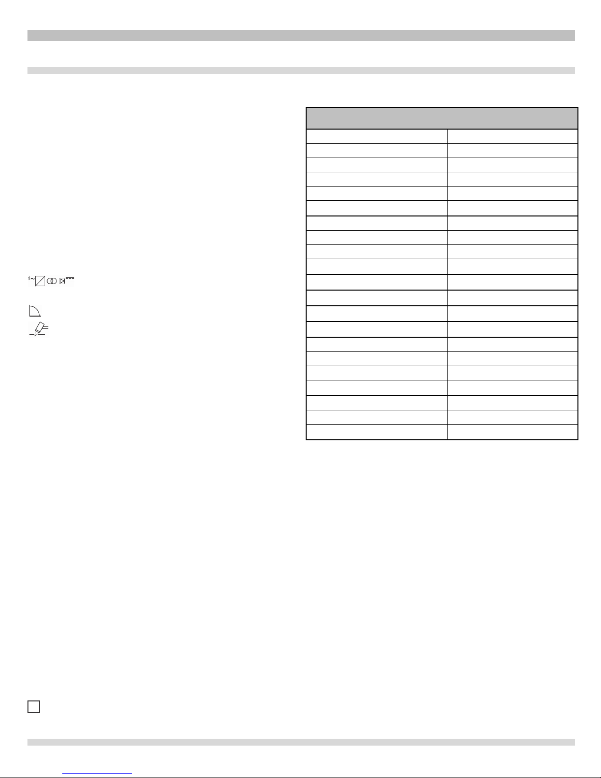
SPECIFICATIONS+
Power+Input+
!!
Voltage!
115!or!230!Volt!
Phase!!
Single!Phase!
Frequency!
50/60!Hertz!
Current!
30!Amps!115!Volt!
!!
20!Amps!230!Volt!
Power+Output+
!!
Duty!Cycle/Rated!Output!
100%!@!19!Amps!
!!
60%!@22!Amps!
!!
35%!@!25!Amps!
Output+Control+
Adjustable!5!‐!25!Amps!
Torch+Cable+Length+
12!Feet!
Ground+Cable+Length+
12!Feet!
Power+Input+Cord+
8!Feet!
Dimensions+
!!
Height!
16!Inches!
Width!
8!Inches !
Depth!
16!Inches!
Weight++
!!
Base!Unit!
29!
Shipping!
33!
SPE CIFICATIONS
Page 6

5
FEATURES
• Inverter portable 30 amp plasma cutter.
• Either 110 volt of 230 volt input with automatic switching.
• Low input amperage requirement.
• Inverter technology allows the plasma cutter to be lightweight (29 Ib.) and still able to perform many
cutting applications.
• The adjustable amperage output of a minimum of 5 amps, allows the cutting of one layer of material
without cutting the second layer.
• The maximum of 25 amps will cut 3/8" steel and sever 1/2".
• Pilot self restart function allows the unit to cut perforated or grid metal.
• Low air pressure LED.
• Air regulator and filter.
• The PLASMA30i includes plasma cutter, torch assembly, ground cable, spare nozzle and electrode.
• Industry-leading technical support of over 30 years of experience by calling 800-ABC-WELD to
speak with a live expert.
Page 7

6
DES CRIPTIO N OF EQ UIPMENT
A Power
cord
B Compressed air fitting (1/4" female gas thread)
C Main power
switch “0” = off “l” = on
D Main power
led
E Pressure regulator
knob (Lift to adjust)
F Pressure gauge
G Thermostat LED
H Ground
cor
d
I Water
trap
L Low air pressure LED
M Cutting current regulator
knob
N Blocked LED; lights when hazardous
conditions
arise.
O LED that lights when the
"SELF-RESTART
PILOT"
function is
active
P Push-button to activate and deactivate the
"SELF-
RESTART
PILOT"
function.
Q Plasma
tor
ch (includes consumable parts).
Q
Page 8

7
THERMAL PROTECTION
This system comes equipped with the following safety
devices:
Overload cutout:
To avoid overload while
cutting.
The LED G (see fig 1) lights when
active.
Pneumatic:
➡
Located on the torch inlet to prevent low air
pressure. The LED L lights when tripped (see fig.1).
Electrical:
1) In the event of a short-circuit between the nozzle
and
electrode during arc
striking
2) In the event of a short-circuit between the contacts
of
the
reed relay on circuit 22 (see exploded drawing).
3) When the electrode is worn to the point it must
be
replaced.
These conditions block the machine, and are
signaled
by
the lit LED N .
4) In addition, this machine is equipped with
automatic
selection of the supply voltage and the following
protections:
A) 230V Power supply: during start-up, the machine
remains blocked
(LED N lit) if the voltage is below
200V. After start-up, the machine runs at as low
as 180V.
B) 115V Power supply: during start-up, the machine
remains blocked
(LED N lit) if the voltage is below
100V. After start-up, the machine runs at as low
as 90V.
Lightweight and Variable Input Voltage Selections
The plasma cutter is able to operate on either 115 volt or 230
volt service using its automatic voltage input feature. The
advanced inverter design requires much less amperage
input thus saving on electricity costs. This along with its
lightweight design, allows it to be used anywhere there is
electric service and compressed air available.
Adjustable Arc Control
The PLASMA30i adjustable output arc control allows the
user to easily cut thin metal, up to 3/8” and sever up to.1/2”.
With the adjustable output control, the cutting arc can be
adjusted to cut one layer of material without cutting the
second layer. This can be extremely useful in the
automotive sector where an outer panel may be removed
without cutting through an inner panel.
Many industrial segments will benefit using the PLASMA30i
because of its multiple input, lightweight design and
adjustable arc feature. The plasma cutter eliminates the
need of using oxygen acetylene cutting techniques that not
only would be cumbersome to move, also more costly.
WARNING
• Do not remove or short-circuit the safety
devices.
• Use only original spare parts.
• Always replace any damaged parts of the
machine with original materials.
• Use only torches type CP40.
• Do not run the machine without its housings.
This would be dangerous to the operator and
anyone else in the work area, and would prevent
the machine fr
om
being cooled properly.
DES CRIPTIO N OF EQUIPMENT cont ’d
Page 9

8
INSTALLATION
Make sure that the supply voltage is either 115 volts and a
minimum of 30 amp service or 230 volt and a minimum of 20
amp service. When mounting a plug, make sure it has an
adequate
capa
city, and that the "yellow/green conductor"
of the power
supply cable is connected to the ground or
“earth” terminal. The blue and brown wires need to be
connected to each of the other pins on the plug.
WARNING
Only skilled personnel should install the machine. All
connections must be carried out according to current
regulations.
See complete listing of safety messages at the beginning of
this manual.
The machine must be installed by qualified personnel.
All connections must be made in compliance with
current safety standards and full observance of safety
regulations (see CEI 26-23 - IEC-TS 62081).
Connect the air supply to the fitting B .
• If the system air contains a considerable amount
of
moisture and oil, it is best to use a drying filter to
avoid
excessive oxidation and wear of the consumer
parts,
damaging the torch and reducing the cutting
speed
and
quality
.
If the air supply comes from a pressure regulator of a
com
pressor or centralized system, the regulator must be set
to
an output pressure of no more than 8 bar (0.8 Mpa) or
116 PSI. If
the
air supply comes from a compressed air
cylinder, the
cylin
der must be equipped with a pressure
regulator. Never connect a compressed air cylinder
directly to the r
egu
lator on the machine! The pressure
could exceed
the capacity of the regulator, which might
explode!
1)
Connect the power cord A : the yellow-green cable
wir
e
must be connected to an efficient grounding
terminal of the plug. The remaining brown and blue
wires must be connected to the supply voltage.
2) Amperage requirements
• 230V 20 amp service.
• 115V 30 amp service.
3) The absorbed current I
1
may be determined a l s o by
reading the technical specifications shown on the
machine under the available supply voltage
U1.
4) Any extension cords must be sized appropriately for
current
I, but are not recommended.
ASS EMBLING THE UN IT/STAR T UP GU IDE
Page 10

9
T U V
W
Fig. 3
Fig. 4
Fig. 2/A
Fig. 2/B
1. Turn the machine on “l” using the switch C . The warning
lamp D will light to indicate that the machine is on.
2. Press the torch trigger briefly to open the flow of
compressed air. Since the arc is not lit, air leaves the torch
for only 5 sec.
3. Now adjust the pressure, shown on the pressure gauge F
to 3.5 bar or 50 psi Lift the knob to adjust. Clockwise will
increase and counterclockwise will decrease. Then lock
the knob by pressing it downward.
4. Connect the grounding clamp to the work piece. The
cutting circuit must not be deliberately placed in direct or
indirect contact with the protective wire except in the work
piece.
If the work piece is deliberately grounded using the
protective conductor, the connection must be as direct as
possible and use a wire of at least the same size as the
cutting current return wire, and connected to the work
piece at the same point as the return wire using the return
wire clamp or a second grounding clamp placed in the
immediate vicinity. Every precaution must be taken to
avoid stray currents.
5. Use the knob M to adjust the cutting current from 5 to 25 A
based on the work at hand.
6. Make sure that the ground clamp and the work piece are in
good electrical contact, especially with painted or oxidized
metal or with insulated coating; connect the clamp as close
as possible to the cutting area.
Do not connect the grounding clamp to the part of
the material that is to be removed.
7. Press the torch trigger to strike the pilot arc. If cutting does
not begin within 2 seconds, the pilot arc goes out; press
the trigger again to re-strike it.
8. Begin cutting as shown in fig. 2a, avoid starting as shown
in fig. 2b
9. Hold the torch upright while cutting.
10. When you have finished cutting and released the trigger,
air will continue to leave the torch for approximately 40
seconds to allow the torch to cool down.
It is best not to turn the machine off until this cooldown period is complete.
• To cut perforated or grid metal, activate the "Pilot self
restart" function using the push-button P (LED O lit). When
you have finished cutting, holding this push-button down
will cause the pilot arc to restart automatically.
Use this function only if necessary to avoid
unnecessary wear on the electrode and nozzle.
•
Should you need to make holes or begin cutting from the
center of the work piece, you must hold the torch at an
angle and slowly straighten it so that the nozzle does not
spray molten metal (see fig. 3). This must be done when
making holes in pieces more than 3 mm or ~.118” thick.
(12 gauge = .105”)
• Should you need to cut several layers of metal, as are
normally used in auto body work, adjust the cutting current
to the minimum values.
For currents between 5 and 10 A it may be helpful to set
the intake pressure to approximately 2 bar or 29 psi.
Turn the machine off when the task is completed.
PLASMA CUT TING - INTRO DUCTION
Page 11

10
INSUFFICIENT PENETRATION
This error may be caused by the
following:
• High speed. Always make sure that the arc fully
pene
trates
the work piece and is never held at a forward angle of more
than 10 -15°. This will avoid incorrect
consump
tion of the
nozzle and burns to the nozzle
holder
.
• Excessively thick work pi ece (see cutting speed
dia
grams, fig. 5).
• Grounding clamp not in good electrical contact with
the
work piece.
• Worn nozzle and electrode.
• Cutting current too low.
NOTE: When the arc does not penetrate, the
molten
metal scraps obstruct the nozzle.
THE CUTTING ARC GOES OFF
This error may be caused
by:
• Worn nozzle, electrode or swirl ring.
• Air pressure too high.
• Supply voltage too low.
REPLACING CONSUMABLE PARTS
Always shut off the machine before replacing
consu
mer parts.
• The electrode must be replaced when it has a crater in the
center approximately 1 mm deep (.039”) or slightly over
1/32”.
• The gas nozzle must be replaced when the hole is no
longer smooth and the cutting capacity is diminished.
• The swirl ring must be replaced when some areas are
blackened. Due to its small size, it is very important to
position it correctly during assembly (see fig. 4).
• The nozzle holder must be replaced when the insulating
part is deteriorated
Make sure that the electrode T, the swirl ring U and
the
gas nozzle V are mounted correctly, and that
the
nozzle holder W is firmly tightened.
If any of these parts are missing, this will interfer
e
with smooth operation of the machine and,
especial
ly,
jeopardize operator safety
SHORTER LIFE OF CONSUMABLE PARTS
This error may be caused by:
• Oil or dirt in the arc intake,
• Unnecessarily long pilot arc,
• Low arc pressure.
HELPFUL HINTS
• If the system air contains considerable amounts of moisture
and oil, it is best to use a drying filter to avoid excessive
oxidation and wear on consumable parts, damage to the
torch and a reduction in the speed and quality of the cutting.
• Make sure that the new electrode and nozzle to be mounted
are thoroughly clean and degreased.
• Always use original spare parts to avoid damaging the
torch.
TROUBLESHOOTING/
CON SUMABLE REPLACEM ENT
Page 12

11
MAINTENANCE
Always cut off the power supply to the machine before any
operation, which must always be carried out by qualified
personnel (CEI 26-29 / IEC 60974-4).
PLASMA CUTTER MAINTENANCE
In the case of maintenance inside the machine, make sure
that the switch C is in position O and that the power cord is
disconnected from the mains.
Even though the machine is equipped with an automatic
condensation drainage device that is tripped each time the
air supply is closed, it is good practice to periodically make
sure that there is no condensation accumulated in the water
trap I (fig.1).
It is also necessary to periodically clean the interior of the
machine from the accumulated metal dust, using compressed air.
PRECAUTIONS AFTER REPAIRS.
After making repairs, take care to organize the wiring so that
there is secure insulation between the primary and
secondary sides of the machine. In particular, make sure
that the casing 50 is mounted (see exploded drawing). Do
not allow the wires to come into contact with moving parts or
those that heat up during operation. Reassemble all clamps
as they were on the original machine, to prevent a
connection from occurring between the primary and
secondary circuits should a wire accidentally break or be
disconnected.
Also mount the screws with geared washers as on the
original machine.
MAINTENANC E
Page 13

12
POS
PART
NUMBER
DESCRIPTION
1
CKSP3001
HOUSING
2
CKSP3002
HANDLE SUPPORT
3
CKSP3003
HANDLE
4
CKSP3004
RING NUT
5
CKSP3005
SUPPORT
6
CKSP3006
GAUGE
7
CKSP3007
REGULATOR
8
CKSP3008
FITTING
9
CKSP3009
SWITCH
10
CKSP3010
COVER
11
CKSP3011
POWER CORD
12
CKSP3012
CABLE OUTLET
13
CKSP3013
BACK PANEL
14
CKSP3014
FAN SUPPORT
15
CKSP3015
MOTOR WITH FAN
16
CKSP3016
INSIDE BAFFLE
17
CKSP3017
CHOKE
18
CKSP3018
RUBBER FOOT
19
CKSP3019
BOTTOM
20
CKSP3020
SOLENOID VALVE
21
CKSP3021
UNION ELBOW
22
CKSP3022
HIGH-FREQ. CIRCUIT
23
CKSP3023
FITTING
24
CKSP3024
TERMINAL BOARD
25
CKSP3025
STRAIN RELIEF
26
CKSP3026
RING NUT
27
CKSP3027
CABLE WITH CLAMP
28
CKSP3028
STRAIN RELIEF
29
CKSP3029
KNOB
30
CKSP3030
FRONT PANEL
31
CKSP3031
PANEL CIRCUIT
32
CKSP3032
PRESSURE SWITCH
33
CKSP3033
SUPPORT
34
CKSP3034
SUPPORT
35
CKSP3035
POWER CIRCUIT
36
CKSP3036
FILTER CIRCUIT
37
CKSP3037
FITTING
38
CKSP3038
FITTING
39
CKSP3039
FITTING
40
CKSP3040
TORCH CONNECTOR
41
CKSP3041
HANDGRIP w/PUSHBUTTON
42
CKSP3042
O.RING
43
PLASMA3006
TORCH BODY (HEAD)
44
PLASMA3004
ELECTRODE (PACK. 5 PCS.)
45
PLASMA3003
SWIRL RING (PACK. 2 PCS.)
46
PLASMA3002
NOZZLE (PACK. 5 PCS.)
47
PLASMA3001
NOZZLE HOLDER
48
CKSP3048
TORCH CABLE
49
PLASMA3007
COMPLETE TORCH
50
CKSP3050
COVER
51
CKSP3051
FRAME
52
CKSP3052
PROTECTION
53
CKSP3053
FRAME
REP LACEMENT PARTS – PART S LIST
WHEN ORDERING SPARE PARTS PLEASE STATE THE MODEL NUMBER
AND SERIAL NUMBER AND PART NUMBER NEEDED.
Page 14

13
CODIFICA COLORI
CABLAGGIO
ELETTRICO
WIRING DIAGRAM
COLOUR CODE
A NERO
BLACK
B ROSSO
RED
C
GRIGIO
GREY
D
BIANCO
WHITE
E VERDE
GREEN
F VIOLA
PURPLE
G
GIALLO
YELLOW
H BLU
BLUE
K
MARRONE
BROWN
J ARANCIO
ORANGE
I ROSA
PINK
CODIFICA COLORI
CABLAGGIO
ELETTRICO
WIRING DIAGRAM
COLOUR CODE
L
ROSA-NERO
PINK-BLACK
M GRIGIO-VIOLA
GREY-PURPLE
N
BIANCO-VIOLA
WHITE-PURPLE
O
BIANCO-NERO
WHITE-BLACK
P GRIGIO-BLU
GREY-BLUE
Q
BIANCO-ROSSO
WHITE-RED
R
GRIGIO-ROSSO
GREY-RED
S BIANCO-BLU
WHITE-BLUE
T NERO-BLU
B
LACK-BLUE
U
GIALLO-VERDE
YELLOW-GREEN
V AZZURRO
BLUE
WIRING D IAGRAM
Page 15

14
Snap-on Tools Company Limited Two (2) Year Warranty
Snap-on Tools Company (the “Seller") warrants only to original purchasers who use the Equipment in their business that
under normal use, care and service, the Equipment (except as otherwise provided herein) shall be free from defects in
material and workmanship for two years from the date of original invoice. Seller does not provide any warranty for
accessories used with the Equipment that are not manufactured by Seller. Seller limits torch assembly to a period of 30 days.
SELLER'S OBLIGATIONS UNDER THIS WARRANTY ARE LIMITED SOLELY TO THE REPAIR OR, AT SELLER'S
OPTION, REPLACEMENT OF EQUIPMENT OR PARTS WHICH TO SELLER'S SATISFACTION ARE DETERMINED TO BE
DEFECTIVE AND WHICH ARE NECESSARY, IN SELLER'S JUDGMENT, TO RETURN THIS EQUIPMENT TO GOOD
OPERATING CONDITION. NO OTHER WARRANTIES, EXPRESS OR IMPLIED OR STATUTORY, INCLUDING WITHOUT
LIMITATION ANY IMPLIED WARRANTY OF MERCHANTABILITY OR FITNESS FOR A PARTICULAR PURPOSE, SHALL
APPLY AND ALL SUCH WARRANTIES ARE HEREBY EXPRESSLY DISCLAIMED.
SELLER SHALL NOT BE LIABLE FOR ANY INCIDENTAL, SPECIAL OR CONSEQUENTIAL COSTS OR DAMAGES
INCURRED BY PURCHASERS OR OTHERS (including, without limitations, lost profits, revenues, and anticipated sales,
business opportunities or goodwill, or interruption of business and any other injury or damage).
This warranty does not cover (and separate charges for parts, labor and related expenses shall apply to) any damage to,
malfunctioning, inoperability or improper operation of the Equipment caused by, resulting from or attributable to (A) abuse,
misuse or tampering; (B) alteration, modification or adjustment of the Equipment by other than Seller's authorized
representatives; (e) installation, repair or maintenance (other than specified operator maintenance) of the Equipment or
related equipment, attachments, peripherals or optional features by other than Seller's authorized representatives; (D)
improper or negligent use, application, operation, care, cleaning, storage or handling; (E) fire, water, wind, lightning or other
natural causes; (F) adverse environmental conditions, including, without limitation, excessive heat, moisture, corrosive
elements, dust or other air contaminants, radio frequency interference, electric power failure, power line voltages beyond
those specified for the Equipment. unusual physical, electrical or electromagnetic stress and/or any other condition outside of
Seller's environmental specifications; (G) use of the Equipment in combination or connection with other equipment,
attachments, supplies or consumables not manufactured or supplied by Seller; or (H) failure to comply with any applicable
federal, state or local regulation, requirement or specification governing welders and related supplies or consumables.
Repairs or replacements qualifying under this Warranty will be performed on regular business days during Seller's normal
working hours within a reasonable time following purchaser's request. All requests for Warranty service must be made during
the stated Warranty period. Proof of purchase date is required to make a Warranty request. This Warranty is nontransferable.
Snap-on Tools Company
Kenosha, Wisconsin 53141-1410
Technical Support Line 800-ABC-WELD
Customer Service and Technical Support 800-ABC-WELD
Monday – Friday 7:00 a.m. – 3:00 p.m. EST
Made in Italy
Snap-on and Wrench “S” are trademarks of Snap-on Incorporated.
©Snap-on Incorporated 2011. All Rights Reserved.
Printed in United States
Snap-on, 2801 80th St., Kenosha, WI 53143
www.snapon.com
WAR RANTY/S ERVICE AND REP AIR
 Loading...