

Page 1

User Manual
TM
Previous Vehicle
and Data
OBD-II/EOBD
Scanner
Tools
Previous Vehicle
Data
O
OBD
S
Tools
BC
canner
and
ZEESC334A Rev. A
BD-II/E
Start
Page 2
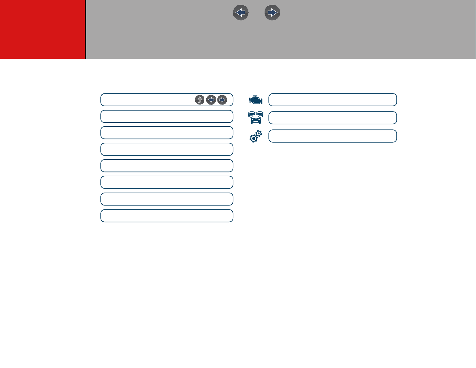
Quick Links
Scanner
ShopStream Connect™
Previous Vehicles & Data
Tools
General Information
Basic Operation & Navigation
Maintenance
Quick Reference Information
Table of Contents (TOC)
Using Page Controls
Wi-Fi Connection
Contents
ii
Page 3

Table of Contents
Table of Contents
Safety Information ....................................................................................... v
Using This Manual ..................................................................................... vii
Section 1: Quick Reference ........................................................................ 1
Section 2: General Information................................................................... 2
Basic Features............................................................................................... 2
Powering the Diagnostic Tool ........................................................................ 3
Vehicle Power ......................................................................................... 3
Internal Battery Pack ............................................................................... 3
AC Power Supply .................................................................................... 4
Technical Specifications ................................................................................ 4
Section 3: Basic Operation and Navigation .............................................. 5
Turning On/Off and Emergency Shutdown .................................................... 5
Turning On .............................................................................................. 5
Turning Off .............................................................................................. 5
Emergency Shutdown ............................................................................. 5
Control Buttons .............................................................................................. 6
Basic Navigation ............................................................................................ 6
Home Screen Layout............................................................................... 6
Home Screen Icons................................................................................. 7
Title Bar ................................................................................................... 7
Common Toolbar Control Icons .............................................................. 8
Scroll Bar................................................................................................. 8
Screen Messages .......................................................................................... 9
Snap-on Messages ................................................................................. 9
General System Messages ..................................................................... 9
Vehicle Communication Messages ......................................................... 9
Section 4: Scanner..................................................................................... 10
Basic Operation ........................................................................................... 10
Scanner Overview ................................................................................. 10
Scanner Demonstration Mode............................................................... 11
Scanner - Starting / Stopping ................................................................ 11
Features and Icons ...................................................................................... 12
Scanner Features.................................................................................. 12
Scanner Control Icons........................................................................... 12
Basic Scanner Operation (Quick Start) ................................................. 13
Data Cable Connection ......................................................................... 13
Vehicle Identification / System Selection .............................................. 14
System Main Menu Options ........................................................................ 16
Codes - View / Scan / Save......................................................................... 17
Viewing Codes ...................................................................................... 17
Clear Codes .......................................................................................... 17
Code Scan ........................................................................................... 17
Viewing and Saving Data ............................................................................ 20
About the Data Buffer ........................................................................... 20
About Cursors ....................................................................................... 21
Pausing and Reviewing Active Data ..................................................... 21
Saving Data Files .................................................................................. 23
Using Zoom........................................................................................... 24
Changing Data Views - PID List / Graphs ...........................
Selecting PIDs to Display (custom display) .......................................... 26
Locking PIDs (to always display at top) ............................................... 26
Using Triggers....................................................................................... 27
Functional Tests .......................................................................................... 30
Section 5: Previous Vehicles and Data ................................................... 32
Previous Vehicles and Data Menu .............................................................. 32
Vehicle History ...................................................................................... 32
View Saved Data .................................................................................. 33
Viewing Codes and Code Scan Results ............................................... 33
Delete Saved Data ................................................................................ 35
Section 6: Tools......................................................................................... 36
Tools Menu.................................................................................................. 36
Connect-to-PC (File Transfer)............................................................... 37
Configure Shortcut Button..................................................................... 37
System Information ............................................................................... 37
Settings ................................................................................................. 38
Section 7: Wi-Fi Connection / Troubleshooting ..................................... 44
Checking if Wi-Fi is On/Off .......................................................................... 44
Checking if Wi-Fi is Connected ................................................................... 44
Wi-Fi Icons (Setup)...................................................................................... 45
Turning Wi-Fi On and Connecting to a Network.......................................... 45
.................. 25
iii
Page 4
Add Network Advanced (Connecting to a hidden network) .........................46
Wi-Fi Testing................................................................................................ 46
Wi-Fi Troubleshooting and Status Messages .............................................. 47
Section 8: ShopStream Connect ™.......................................................... 50
Using SSC (Connecting to your PC)............................................................ 50
SSC Main Screen ........................................................................................ 51
Scanner DataViewer ....................................................................................52
Image Viewer...............................................................................................52
Printing the Code Scan Report ....................................................................53
Customizing the Code Scan Report............................................................. 54
Software Upgrades and Updates................................................................. 55
End User License Agreement ............................................................... 56
Section 9: Maintenance............................................................................. 57
Cleaning and Inspecting the Diagnostic Tool...............................................57
Cleaning the Touch Screen................................................................... 57
Battery Pack Service.................................................................................... 57
Safety ................................................................................................... 57
Ordering a New Battery Pack ................................................................ 58
Removing / Installing the Battery Pack.................................................. 58
Disposing of the Battery Pack ............................................................... 59
Table of Contents
Legal Information....................................................................................... 60
iv
Page 5
Safety Information
READ ALL INSTRUCTIONS
For your own safety, the safety of others, and to prevent damage to the produ c t and
vehicles upon which it is used, it is important that all instructions and safety
messages in this manual and the accompanying Important Safety Instructions
manual be read and understood by all persons operating, or coming into contact
with the product, before operating. We suggest you store a copy of each manual
near the product in sight of the operator.
For your safety, read all instructions. Use your diagnostic tools only as described in
the tool user’s manual. Use only manufacturer recommended parts and
accessories with your diagnostic tools.
This product is intended for use by properly trained and skilled professional
technicians. The safety messages presented throughout this manual and the
accompanying Important Safety Instructions manual are reminders to the operator
to exercise extreme care when using this product.
There are many variations in procedures, techniques, tools, and parts for servicing
vehicles, as well as in the skill of the individual doing the work. Because of the vast
number of test applications and variations in the products that can be tested with
this instrument, we cannot possibly anticipate or provide advice or safety messages
to cover every situation. It is the responsibility of the technician to be
knowledgeable of the system being tested. It is essential to use proper service
methods and test procedures. It is important to perform tests in an appropriate and
acceptable manner that does not endanger your safety, the safety of others in the
work area, the equipment being used, or the vehicle being tested.
Read, understand and follow all safety messages and instructions in this manual,
the accompanying Important Safety Instructions manual, and on the test
equipment.
Environmental Conditions:
• This product is intended for indoor use only
• This product is rated for Pollution Degree 2 (normal conditions)
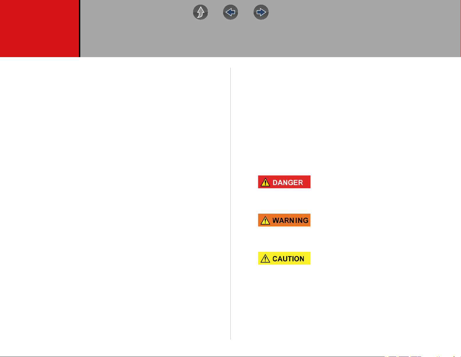
Safety Signal Words
All safety messages contain a safety signal word that indicates the level of the
hazard. An icon, when present, gives a graphical description of the hazard. Safety
Signal words are:
Indicates an imminently hazardous situation which, if not avoided, will result in
death or serious injury to the operator or to bystanders.
Indicates a potentially hazardous situation which, if not avoided, could result in
death or serious injury to the operator or to bystanders.
It is assumed that the operator has a thorough understanding of vehicle systems
before using this product. Understanding of these system principles and operating
theories is necessary for competent, safe and accurate use of this instrument.
Before using the equipment, always refer to and follow the safety messages and
applicable test procedures provided by the manufacturer of the vehicle or
equipment being tested. Use the product only as described in it’s user manual. Use
only manufacturer recommended parts and accessories with your product.
Indicates a potentially hazardous situation which, if not avoided, may result in
moderate or minor injury to the operator or to bystanders.
v
Page 6
Safety Information Safety Message Conventions
Safety Message Conventions
Safety messages are provided to help prevent personal injury and equipment
damage. Safety messages communicate the hazard, hazard avoidance and
possible consequences using three different type styles:
• Normal type states the hazard.
• Bold type states how to avoid the hazard.
• Italic type states the possible consequences of not avoiding the haza rd.
An icon, when present, gives a graphical description of the potential hazard.
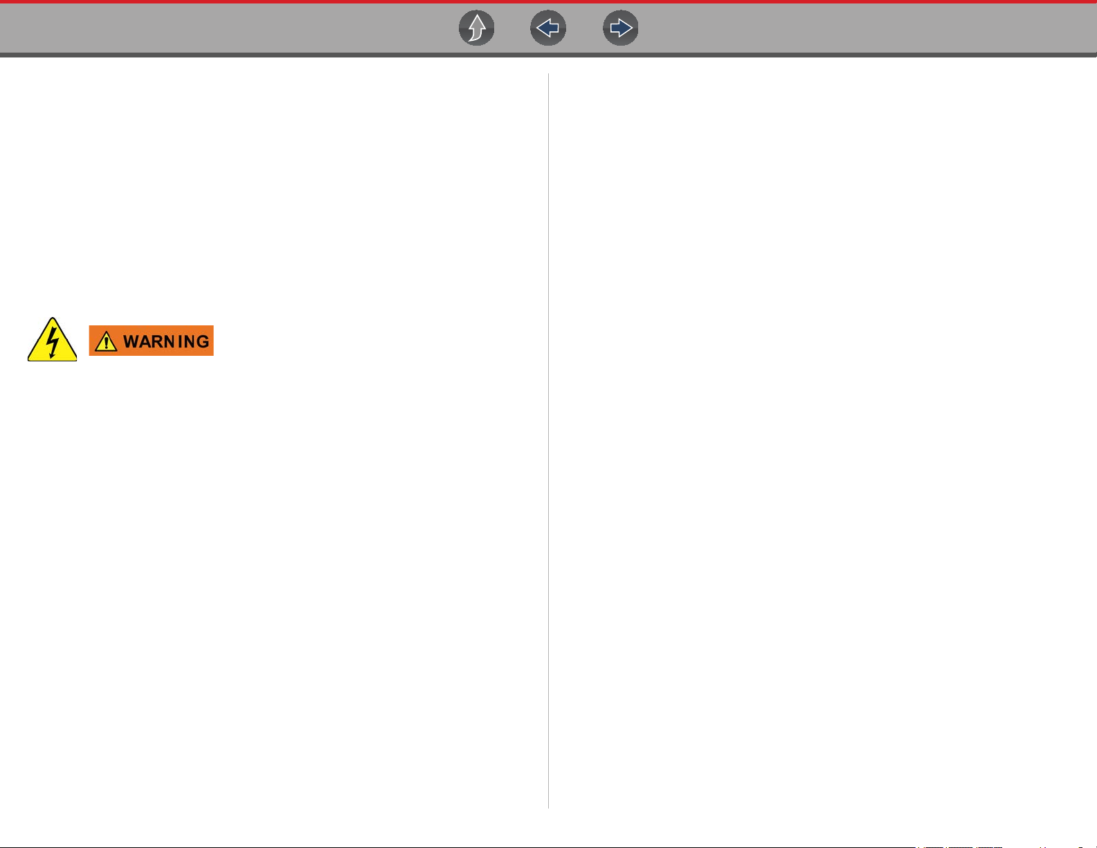
Safety Message Example
Risk of electric shock.
• Prior to recycling the battery pack, protect exposed terminals with heavy
insulating tape to prevent shorting.
• Disconnect all test leads and turn diagnostic tools off before removing the
battery pack.
• Do not attempt to disassemble the battery or remove any component
projecting from or protecting the battery terminals.
• Do not expose the diagnostic tool or battery pack to rain, snow, or wet
conditions.
• Do not short circuit the battery terminals.
Electric shock can cause injury.
Important Safety Instructions
For a complete list of safety messages, refer to the accompanying Import ant Safety
Instructions manual.
SAVE THESE INSTRUCTIONS
vi
Page 7
Using This Manual
IMPORTANT
Hyperlinks
Selectable hyperlinks are provided throughout this manual to quickly take you to
related topics, procedures, and websites. Hyperlinks are identified by Blue colored
text.
Text Hyperlink Ex ample: http://diagnostics.snapon.com
Page Navigation Controls
The following navigation controls are provided on the top of each page of the user
manual. They can be used in addition to the viewer controls in the toolbar.
Icon Description
Quick Links
Menu
Jump Back
Jump Forward
Opens the Quick Links menu within the Table of Contents (TOC) section.
From Quick Links you can link to most topics in this manual.
Click to move back one page.
Click to move forward one page.
Content
This manual is intended to be used for P1000 motorc ycle scanne r
operations. For automotive operations, see the Ethos Edge user manual
at: http://diagnostics.snapon.com/usermanuals
This manual contains basic operating instructions and is structured in a manner to
help you become familiar with your diagnostic tool features and perform basic
operations.
The illustrations in this manual are intended as reference only and may not depict
actual screen results, information, functions or standard equipment. Contact your
sales representative for availability of other functions and optional equipment.
Conventions
The following conventions are used.
Terminology
The term “Vehicle” is used throughout this manual, and is used to describe or refer
to a motorcycle in general terms.
The terms “Scanner” and “Scanner function” are used to describe the Scanner
Function(s) of the diagnostic tool.
Examples:
• Select Scanner from the Home screen.
• From the Scanner main menu select Continue.
• The Scanner function provides many diagnostic tests.
The term “select” describes tapping/touching an icon on the touch screen, or
highlighting an icon or menu choice and then selecting the confirmation menu
choice such as Continue, Accept, OK, Yes, or other similar choice.
vii
Page 8
Using This Manual Notes and Important Messages
NOTE
IMPORTANT
IMPORTANT
Abbreviated example for the following procedure: “Select Brightness”
1. Navigate to and highlight the Brightness selection.
2. Select OK, or similar, button.
Symbols
Different types of arrows are used. The “greater than” arrow (>) indicates an
abbreviated set of selection (navigation) instructions.
Abbreviated example for the following procedure: “Select Tools > Connect-to-PC”
1. Select Tools from the home screen.
2. Highlight Connect-to-PC on the Tools menu.
3. Select Connect-to-PC.
The solid arrows (e, c, d, b) are navigational instructions for the four directions of
the directional buttons.
Example: Press the down d arrow.
Bold Text
Bold emphasis is used in procedures to highlight selectable items such as control
buttons, icons and menu options.
Example: Press the OK button
Notes and Important Messages
The following messages are used.
Important
IMPORTANT indicates a situation which, if not avoided, may result in damage to the
test equipment or vehicle.
Example:
Do not disconnect the data cable while the diagnostic to ol is
communicating with the ECM.
Read all applicable Safety Information before using this diagnostic tool!
Procedures
An arrow icon in the left-margin area indicates a procedure.
Example:
z To change screen views:
1. Select the Graph icon.
The dropdown menu displays.
2. Select an option from the menu.
The screen layout changes to the format selected.
Notes
A NOTE provides helpful information such as additional explanations, tips, and
comments.
Example:
For additional information refer to...
viii
Page 9
Section 1 Quick Reference
NOTE
Finding the Diagnostic Tool Serial Number
and Software Version
The diagnostic tool serial number is located on the back of the diagnostic tool
housing. The serial number can also be viewed onscreen from the System
Information screen (Tools > System Information) see System Information on
page 37,
The diagnostic tool software version can be viewed onscreen from the System
Information screen (Tools > System Information) see System Information on
page 37.
Support Contact Information
Phone / E-mail - Technical Assistance
1-800-424-7226 / diagnostics_support@snapon.com
or use our online contact form
- https://www1.snapon.com/diagnostics/us/Contact
Website Links:
Snap-on Diagnostics and Information
• http://diagnostics.snapon.com
Manuals / Technical Documentation - The information in this manual is
periodically revised to ensure the latest information is included. Download the
latest version of this manual and other related technical documentation at:
• http://diagnostics.snapon.com/usermanuals
For technical assistance in all other markets, contact your selling agent.
ShopStream Connect
Download ShopStream Connect our free PC-based companion software used to
print, transfer, save, manage, review, annotate, e-mail the saved or recorded files on
your Snap-on diagnostic tool. See ShopStream Connect ™ on p age50
Website URL - http://diagnostics.snapon.com/ssc
Printing Data and Screenshots
Use ShopStream Connect to print code scan reports, data files and screenshots from
the diagnostic tool. See ShopStream Connect ™ on page 50.
Accessories
Available Smart Vehicle Interface (SVI) adapters:
• HARLEY-DAVIDSON (HAR-2)
• BMW (BM-2)
• INDIAN and VICTORY (POL-1)
• DUCATI (DUC-1)
• SUZUKI (SUZ-1)
• HONDA (HON-2)
• KAWASAKI (KAW-1) and (KAW-2)
• YAMAHA (YAM-1)
Items in the list above are subject to change, contact your sales representative
to purchase Smart Vehicle Adapters (SVIs) for other Motorcycle
manufacturers.
Find diagnostic tool accessories using our Interactive Accessories Catalog: visit
http://diagnostics.snapon.com and enter “accessories catalog” in the Search field.
1
Page 10
Section 2 General Information
IMPORTANT
Previous Vehicle
and Data
OBD-II/EOBD
Scanner
Tools
P
and Data
O
D
S
r
Tool
2
1
1
2
3
The P1000™ is a multi-functional diagnostic tool designed for motorcycle and
automotive use.
This manual is intended to be used for P1000 motorcycle s canner
operations. For automotive operations, see t he Ethos Edge user manual
at: http://diagnostics.snapon.com/usermanuals
This section describes basic feature locations, how the diagnostic tool is powered
and basic specifications.
Main Topic Links
• Basic Features page 2
• Powering the Diagnostic Tool page 3
– Vehicle Power page 3
– Internal Battery Pack page 3
– AC Power Supply page 4
• Technical Specifications page 4
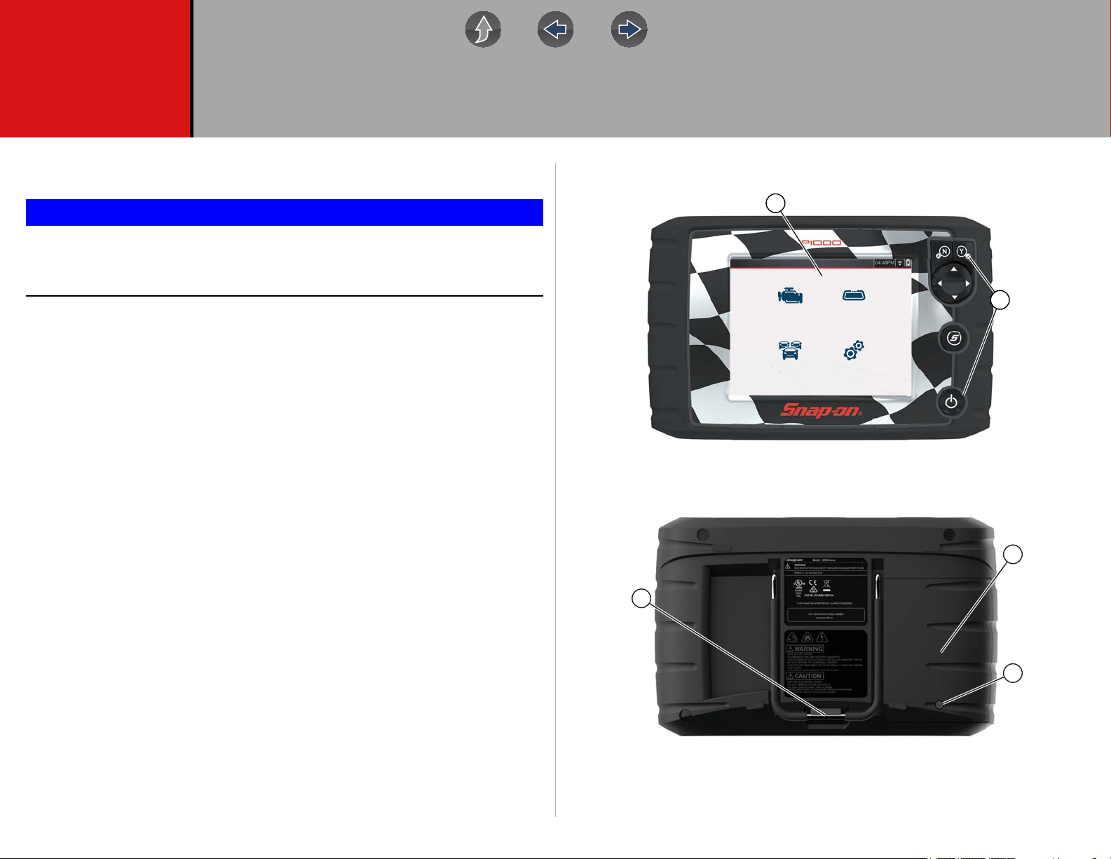
2.1 Basic Features
canne
revious Vehicle
1— Touch Screen
2— Control Panel
Figure 2-1 Front view
BD-II/EOB
s
1— Built-in Stand
2— Battery Cover
3— Batter Cover Screw
Figure 2-2 Back view
2
Page 11
General Information Powering the Diagnostic Tool
IMPORTANT
IMPORTANT
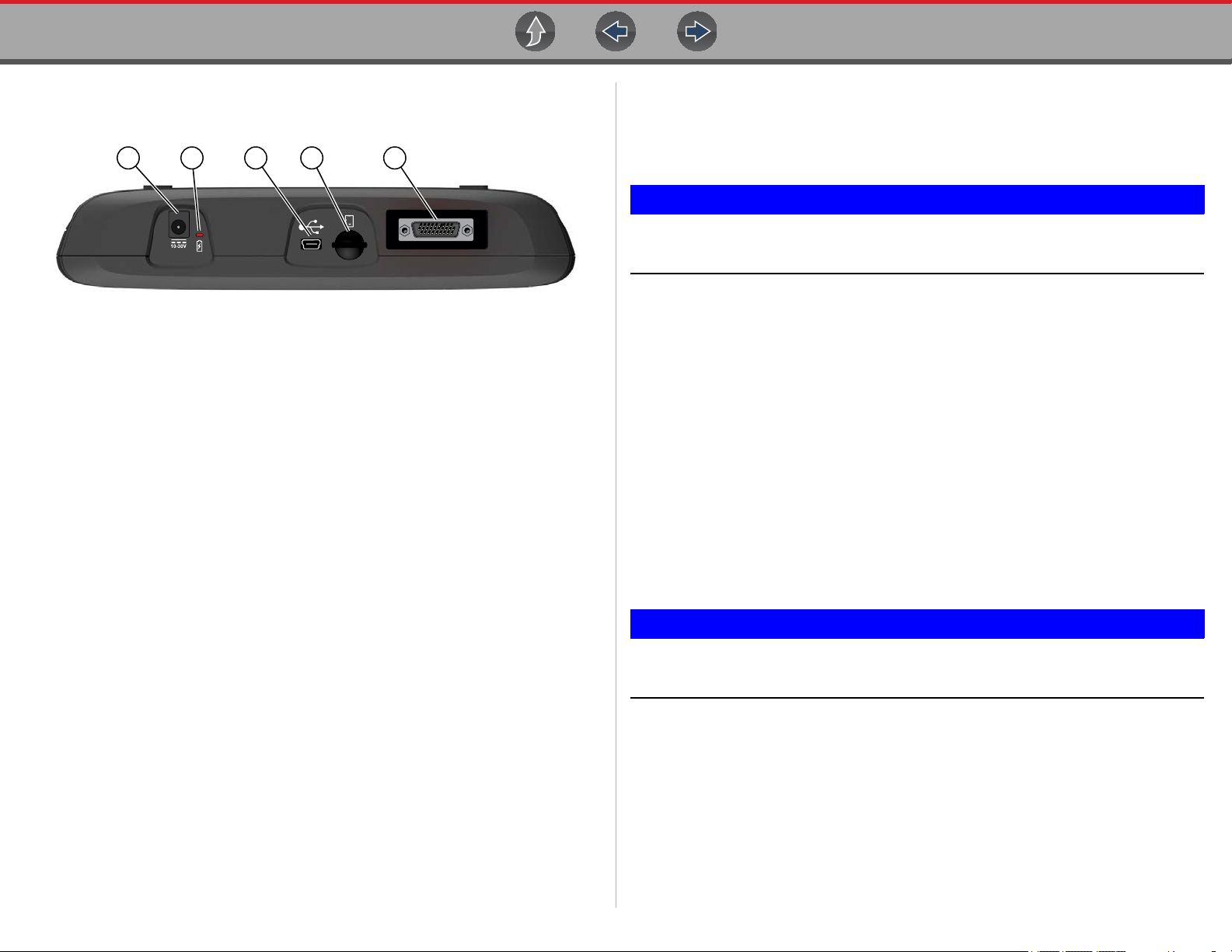
Connectors and jacks for data communication cables and the AC power supply are
located on the top of the diagnostic tool.
1 2 3 4 5
Figure 2-3 Top view
1— Power Supply Jack - AC power supply connection
2— Battery Status Indicator LED
3— Mini USB Jack
personal computer
4— Micro secure digital (uSD) Card - contains operating system programming.
IMPORTANT The uSD card must be installed for the diagnostic tool to operate. Do
not remove the uSD card while the diagnostic tool is powered on.
5— Data Cable Connector - Data cable connection used to connect the diagnostic
tool to a motorcycle diagnostic connector.
- USB cable connection used to transfer saved data files to a
motorcycle diagnostic connector power circuit. See Data Cable Connection on
page 13 for additional data cable information.
Use the supplied power accessory cable when testing models that do not have
battery power (B+) available on the motorcycle diagnostic connector.
Never connect the power accessory cable when the diagnostic tool is
communicating with a vehicle.
2.2.2 Internal Battery Pack
The diagnostic tool can be powered from the internal rechargeable battery pack. A
fully charged battery pack provides sufficient power for about 3 hours of continuous
operation. For battery pack removal and installation instructions see, Remov in g /
Installing the Battery Pack on page 58.
Battery Pack Charging
Battery charging occurs whenever the data cable is connected to a motorcycle
diagnostic connector. Battery charging also occurs when the AC power supply is
connected to a live AC power source, and connected to the diagnostic tool. Use the
supplied AC power supply to charge the battery pack.
2.2 Powering the Diagnostic Tool
Your diagnostic tool can receive power from any of the following sources:
• Vehicle Power
• Internal Battery Pack
• AC Power Supply
2.2.1 Vehicle Power
The diagnostic tool is designed to be powered from the vehicle. Most motorcycles
have vehicle battery power (B+) available on the motorcycle diagnostic connector.
The diagnostic tool is powered through the Data Cable when connected to the
motorcycle diagnostic connector.
A green LED indicator on the motorcycle diagnostic connector end of the data
cable, illuminates when power is being supplied to the cable. If the LED fails to
illuminate, check that the data cable is properly connected and then check the
Insert the end of the AC power supply cable into the diagnostic too power supply
jack, then connect the AC power supply to an approved AC power source.
Only use the supplied AC power supply . Never connect the power supply
to the diagnostic tool when the tool is communicat ing with a ve hicle.
3
Page 12
General Information Technical Specifications
IMPORTANT
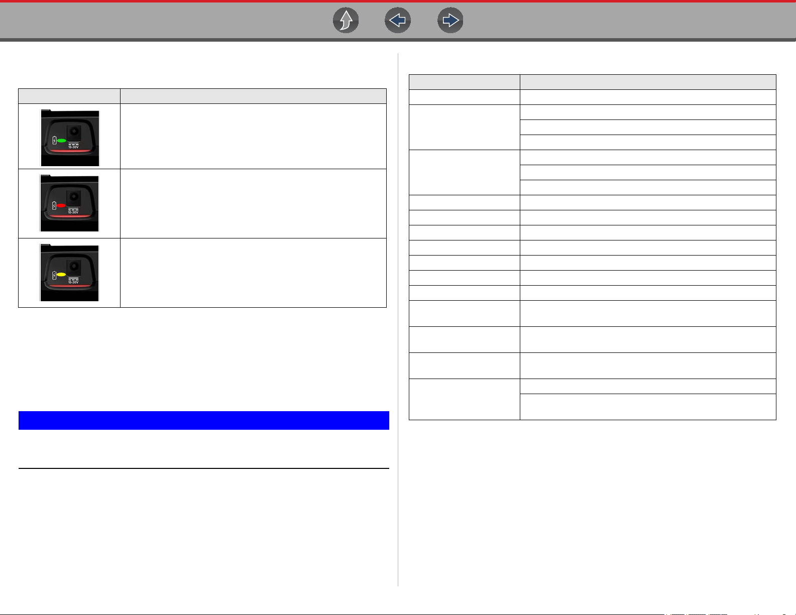
The Battery Status Indicator LED (located next to the power supply jack) indicates
battery status.
Battery Status LED Description
Green - battery is fully charged, or the diagnostic tool is being
powered by the AC power supply.
Red - battery is charging
Amber - indicates a battery issue. This is usually caused by
excessive battery temperature (above 104°F/40°C), which
disables charging. Allow the diagnostic tool to cool down before
continuing operation.
2.2.3 AC Power Supply
The diagnostic tool can be powered from a standard AC outlet using the AC power
supply. The AC power supply converts alternating current (AC) to direct current
(DC) to power the diagnostic tool. The connector on the end of the output cable of
the AC power supply connects to the AC power supply jack on top of the diagnostic
tool. Use only the AC power supply provided.
2.3 Technical Specifications
Item Description / Specification
Touch Screen Resistive Touch Panel
5.6 inch diagonal, LCD TFT
Display
Battery Pack
Operating System SMX
Processor Motorola
Input Operating Voltage 10 to 30VDC
AC Power Supply Rating Input 110-240VAC, Output 15VDC - 2A
Width 8.90 in. (226 mm)
Height 5.67 in. (144 mm)
Depth 1.75 in. (44.5 mm)
Weight (including battery
pack)
Operating Temperature
Range (ambient)
Storage Temperature
(ambient)
Environmental Conditions
640 x 480 resolution
24 bit color
Rechargeable lithium-ion battery pack
Approximately 3 hour run time
Approximately 5 hour charge time
2.1 lb (952 g)
At 0 to 90% relative humidity (non-condensing)
32 to 113°F (0 to 45°C)
At 0 to 70% relative humidity (non-condensing)
–4 to 140°F (–20 to 60°C)
This product is intended for indoor use only
This product is rated for Pollution Degree 2 (normal
conditions)
Never connect the AC power supply to the diagnostic tool when t he
diagnostic tool is communicating with a vehicle.
4
Page 13
Section 3 Basic Operation and Navigation
IMPORTANT
IMPORTANT
IMPORTANT
This section describes basic diagnostic tool operation, navigation, screen layout,
icon functions, and screen messages. Before you operate the diagnostic tool, make
sure the battery pack is fully charged or the diagnostic tool is powered by the AC
power supply.
This manual is intended to be used for P1000 motorcycle s canner
operations. For automotive operations, see t he Ethos Edge user manual
at: http://diagnostics.snapon.com/usermanuals
Main Topic Links
• Turning On/Off and Emergency Shutdown page 5
• Control Buttons page 6
• Basic Navigation page 6
• Home Screen Icons page 7
• Common Toolbar Control Icons page 8
• Screen Messages page 9
3.1 Turning On/Off and Emergency
Shutdown
The following sections describe how to turn the diagnostic tool on and off and how
to perform an emergency shutdown.
3.1.2 Turning Off
All vehicle communication must be stopped BEFORE turning off the
diagnostic tool. A warning message displays if you atte mpt to t urn the
diagnostic tool off while communicati ng with the vehicle. Forcing a shut
down while communicating may lead to control module problems on
some models. Never disconnect the Data Cable wh en the diagnostic tool
is communicating with the vehicle.
z To turn off the diagnostic tool:
1. Press the N/Cancel button or select the Back or Home icon to navigate to the
Home screen.
If applicable, a “stopping communication” message appears briefly before the
Home screen displays.
2. If applicable, disconnect the Data Cable from the motorcycle.
3. Press and release the Power button.
A confirmation screen displays.
4. Press the Y/Accept button or select OK from the menu to turn the diagnostic
tool off. To continue operating, press the N/Cancel button or select Cancel
from the menu.
3.1.3 Emergency Shutdown
3.1.1 Turning On
To manually turn on the diagnostic tool, press and release the Power button
(Figure 3-1).
The diagnostic tool will automatically turn on when:
• a live AC power supply is connected to the diagnostic tool
• the Data Cable is connected to a motorcycle (that has 12VDC at the motorcycle
diagnostic connector)
Using the emergency shutdown procedure while communicating may
lead to control module problems on some models.
During normal operation turn the diagnostic tool off using the Turning Off procedure
above. The emergency shutdown procedure should only be used If the diagnostic
tool does not respond to navigation or control buttons or exhibits erratic operation.
To force an emergency shutdown, press and hold the Power button for five
seconds until the diagnostic tool turns off.
5
Page 14
Basic Operation and Navigation Control Buttons
Previous Vehicle
and Data
OBD-II/EOBD
Scanner
Tools
Previous Vehicle
and Data
O
OBD
S
Tools
1
2
3
4
5
Previous Vehicle
and Data
OBD-II/EOBD
Scanner
Tools
1
2
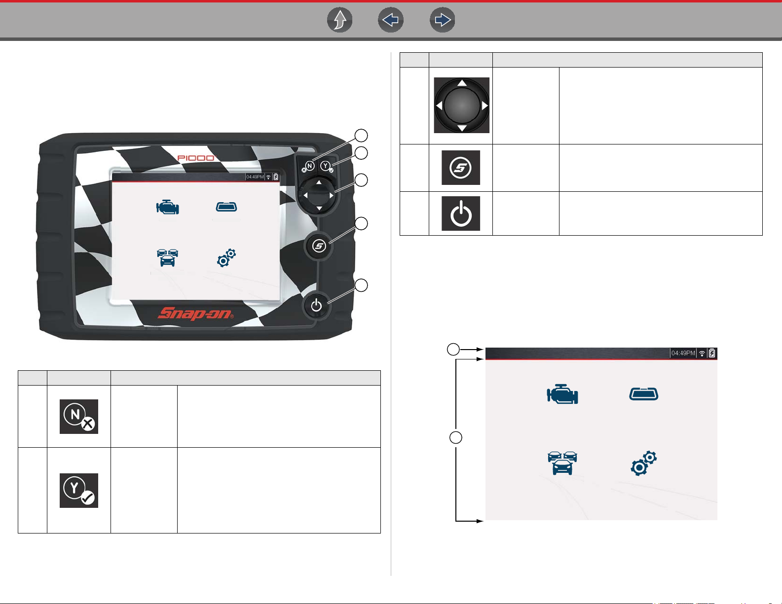
3.2 Control Buttons
There are four “push type” control buttons and one “thumb pad rocker type” multidirectional button located on the right side of the diagnostic tool. All other diagnostic
tool operations are controlled through the touch screen.
canner
BD-II/E
Item Button Description
Buttons move the cursor or highlight in their
Directional -
3
Thumb pad
rocker type
buttons
respective direction:
• Up (b)
• Down (d)
• Left (e)
• Right (c)
S (Shortcut) -
4
Push type
button
Power (On/
5
Off) - Push
type button
Programmable function button that can provide a
shortcut for performing a variety of routine tasks.
Refer to
page 37
Configure Shortcut Button on
for additional information.
Turns the diagnostic tool on and off. Also, press
and hold for 5 seconds for emergency shutdown.
3.3 Basic Navigation
3.3.1 Home Screen Layout
The Home screen includes a title bar and main body. The Home screen contains
the primary diagnostic tool function icons.
Figure 3-1 Front view
Item Button Description
• To exit a menu or program.
N/Cancel -
1
Push type
button
• To close an open list and return to the
previous menu or screen.
• To answer “No” when a yes/no choice is
given.
• To confirm a selection from a menu or
program.
• To select an item that was highlighted using
the direction arrows.
• To advance to the next screen in a series.
• To answer “Yes” when a yes or no choice is
given.
Y/Accept -
2
Push type
button
1— Title Bar
2— Main Body
Figure 3-2 Home screen
6
Page 15
Basic Operation and Navigation Basic Navigation
3.3.2 Home Screen Icons
Each available diagnostic tool function is represented by a icon on the Home
screen. Select an icon from the Home screen to start a function. You can also use
the control buttons to select an icon. Use the directional button to highlight the
desired function and then press the Y/Accept to select it.
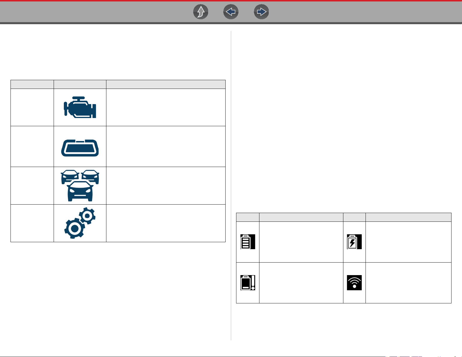
Function Name Function Icon Description
Used to communicate with the control systems of
a motorcycle. This function allows you to retrieve
Scanner
OBD-II/EOBD
Previous
Vehicles &
Data
diagnostic trouble codes (DTCs), view PID data
and perform diagnostic tests. See
page 10
Allows you to access generic automotive
OBD-II/EOBD data and tests without identifying
the vehicle being tested.
See the Ethos Edge user manual at:
http://diagnostics.snapon.com/usermanuals
for instructions.
Allows you to quickly reconfigure the diagnostic
tool to a recently tested vehicle and to access
saved data files.See
Data on page 32
for details.
Previous Vehicles and
for details.
Scanner on
3.3.3 Title Bar
The title bar (Figure 3-2) at the top of the screen provides basic information about
current diagnostic tool operating conditions. Title bar options vary depending upon
motorcycle make and model, what function is active, what test is being performed,
or what menu is selected. The title bar contains information only, there are no
selectable items.
Elements of the Title bar let you know at a glance:
• Which diagnostic tool function is active
• The current time
• Wi-Fi signal strength
• The source and status of the power being supplied to the diagnostic tool
A real time clock displays to the left of the power supply icon. The clock is powered
by a dedicated internal battery, so the correct time is maintained even when the
main battery pack is discharged. Use the Tools function to set the clock and format
how time is displayed. See Clock Settings on page 41 for additional information.
The Title bar displays other information that varies depending upon what functions
are being performed. Other information may include:
• The identification (ID) of the motorcycle
• The name of the active menu or function
• The name of the test being performed
Too ls
Allows you to adjust diagnostic tool settings to
your personal preferences and perform other
special functions. See
details.
Tools on page 36 for
Icon Function Icon Function
Full Battery Charge Level -
Indicates power is being supplied
by the internal battery pack.
Horizontal bars diminish as the
battery discharges.
Low Battery Charge Level -
Indicates the internal battery pack
is low and needs to be recharged
immediately. A warning message
will also display on the screen
when the battery gets low.
7
External Power Connected -
Indicates power is being supplied
through the data cable connection
to a vehicle or by the AC Power
Supply and charging the battery
pack.
Wi-Fi Signal Strength - Indicates
signal strength of the wireless
network connection.
3 bars - full strength signal
1 bar - weak signal
Page 16
Basic Operation and Navigation Basic Navigation
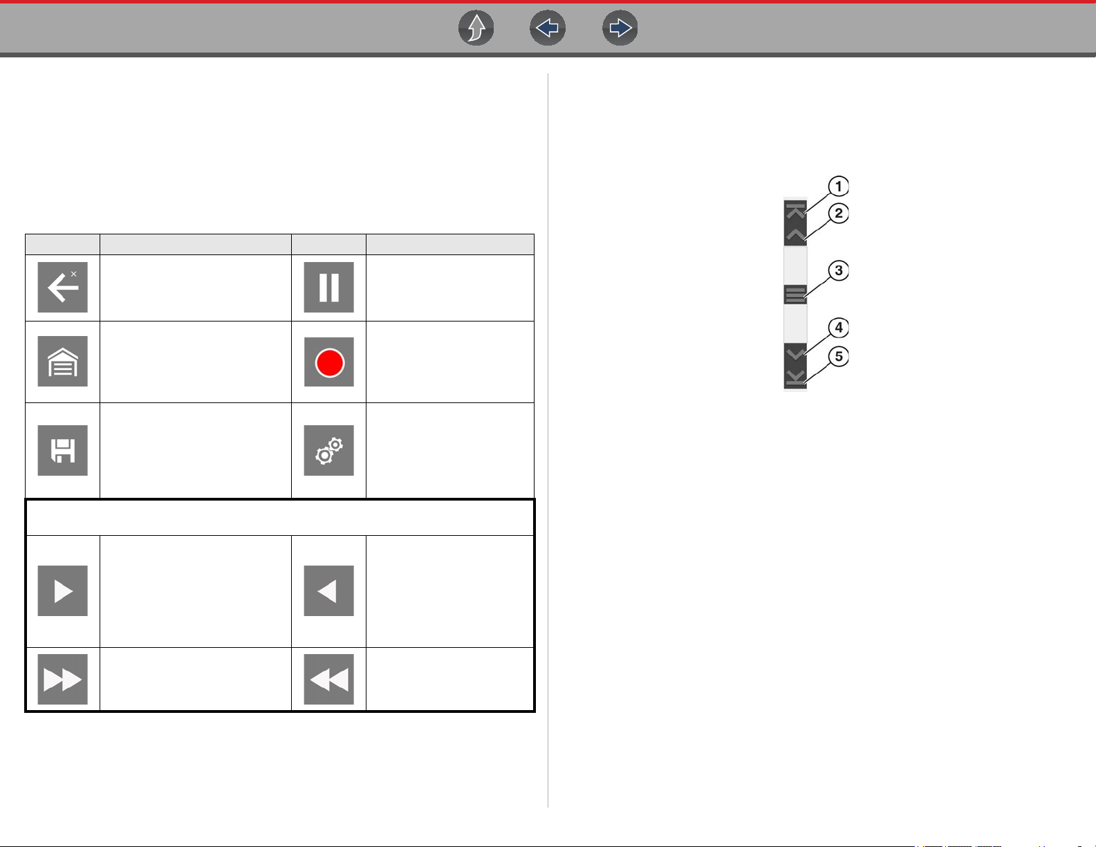
3.3.4 Common Toolbar Control Icons
Common control icon functions are described in the following table. Specific
function control icons are described in their applicable sections. Displayed control
icons vary depending on the active function or test.
Select a control icon to perform a function. You can also use the control buttons to
select an icon. Use the directional button to highlight the desired function and then
press the Y/Accept button to select it.
Icon Function Icon Function
Back - Returns to the previously
viewed screen. Icon is located
on the left-hand edge of the
toolbar.
Home - Returns to the Home
screen. Icon is located next to
the Back icon on the left side of
the toolbar.
Save - Writes data from buffer
memory to a file. The saved
“movie” file can be accessed for
future reference by selecting
Previous Vehicles and Data >
View Saved Data.
The icons below are used to navigate through paused or saved data (“movie”) files
during review.
Step Forward - allows forward
movement in singular steps.
(Note: To quickly step forward
during Scanner data review,
press and hold the icon down.)
Pause - Indicates PID data
from the motorcycle is being
displayed. Selecting pauses
data collection.
Record - Indicates the data
being displayed is paused
and not being updated.
Selecting resumes data
collection.
Too ls - Opens the tools
menu.
Step Back - allows
backward movement in
singular steps.
(Note: To quickly step
backward during Scanner
data review, press and hold
the icon down.)
3.3.5 Scroll Bar
A vertical scroll bar appears along the right-hand edge of the screen when
additional data expands above or below what is currently on the screen
(Figure 3-3).
Figure 3-3 Scroll bar
1— Beginning - Moves to beginning of data displayed.
2— Step up - Moves up one increment of the data displayed.
3— Slider (position indicator) - Select and drag the Slider to scroll through
data. The slider indicates the relative position of the current screen to the
total available data.
4— Step down - Moves down one increment of the data displayed.
5— End - Moves to end of data displayed.
The Up and Down directional buttons can also be used to move through the data
one line at a time. Press and hold a directional button to rapidly scroll through data.
Skip Forward - allows forward
movement in multiple steps.
Skip Back - allows
backward movement in
multiple steps.
8
Page 17
Basic Operation and Navigation Screen Messages
3.4 Screen Messages
3.4.1 Snap-on Messages
Periodically messages will be displayed to inform you of software updates and
upgrades, as well as other important information.
These messages require confirmation to resume tool operation. Select Confirm or
OK to resume operation.
To receive messages from Snap-on, turn WiFi on, see Wi-Fi Connection /
Troubleshooting on page 44.
3.4.2 General System Messages
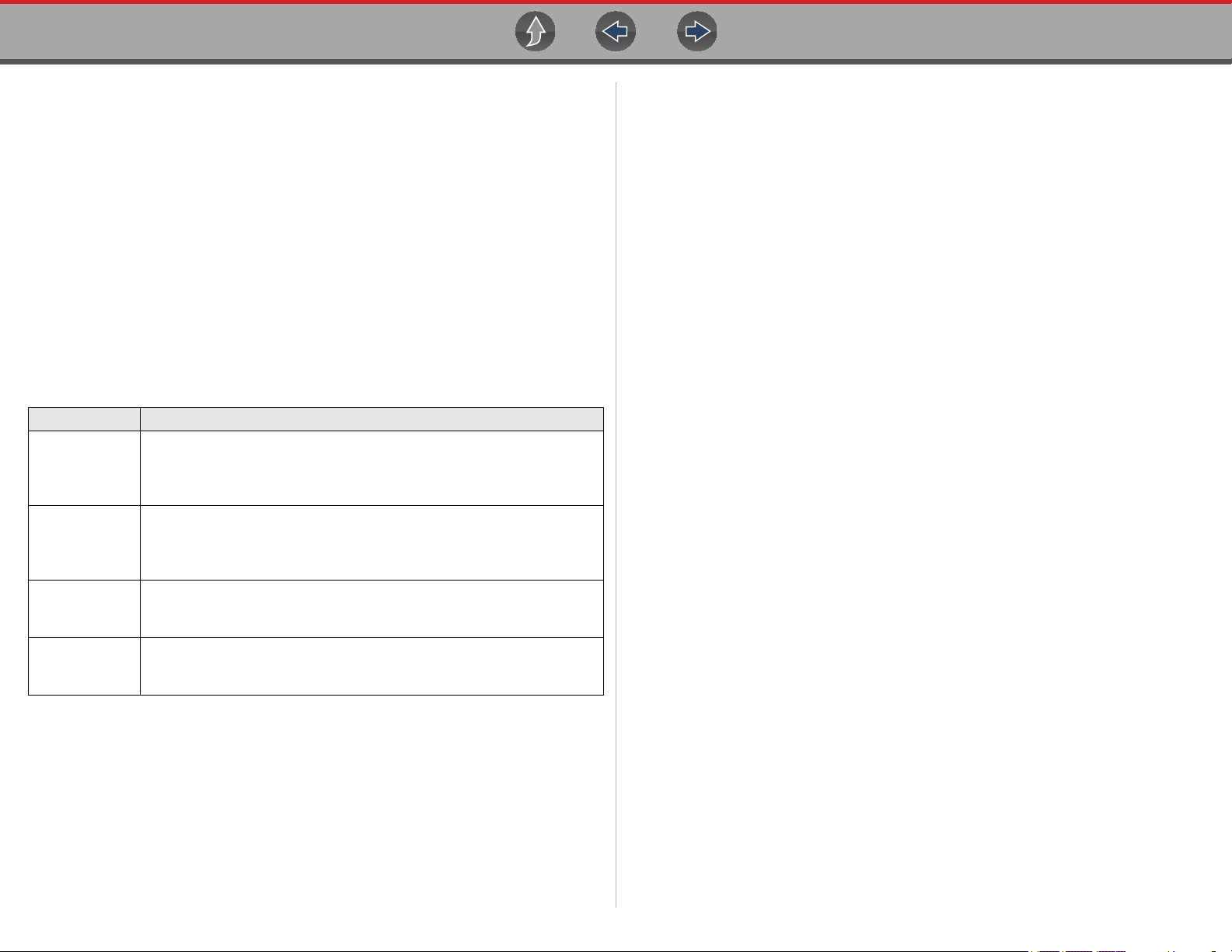
There are four types of general system messages that may be displayed:
Message Type Description
Loading and connecting messages display when the diagnostic tool is
Loading and
Connecting
Confirmation
Warning
Error
performing an internal operation, such as loading a database,
establishing communications with the vehicle, or initiating a test. The
message automatically clears once the internal operation is complete.
Confirmation messages inform you when you are about to perform an
action that cannot be reversed or when an action has been initiated that
requires a confirmation to continue.When a response is not required, the
message displays briefly, then disappears.
Warning messages inform you when completing the selected action may
result in an irreversible change or in the loss of data. A confirmation is
required to continue
Error messages inform you when a system or procedural error has
occurred, for example if the data cable becomes disconnected during
operation.
3.4.3 Vehicle Communication Messages
When “no communication” messages are displayed, it indicates the diagnostic tool
and the motorcycle electronic control module(s) are not communicating.
The following conditions cause “no communication” messages to display:
• The diagnostic tool is unable to establish a communication link with the
motorcycle.
• The motorcycle is not equipped with the system that was selected.
• There is a loose connection.
• There is a blown fuse.
• There is a wiring fault on the motorcycle.
• There is a circuit fault in the data cable or adapter.
• Incorrect motorcycle identification (make/model) was entered.
9
Page 18

Section 4 Scanner
IMPORTANT
This section describes the basic operation of the Scanner function.
The Scanner icon is located on the Home screen.
The Scanner function allows your diagnostic tool to communicate
with the control modules of the motorcycle being serviced. This
allows you to perform tests, view diagnostic trouble codes (DTCs),
and live data parameters from various vehicle systems such as the
engine, antilock brakes (ABS), body control module and more.
This manual is intended to be used for P1000 motorcycle s canner
operations. For automotive operations, see t he Ethos Edge user manual
at: http://diagnostics.snapon.com/usermanuals
Main Topic Links
• Scanner Overview page 10
• Scanner Demonstration Mode page 11
• Features and Icons page 12
• Scanner - Starting / Stopping page 11
• Scanner Control Icons page 12
• Basic Scanner Operation (Quick Start) page 13
• Data Cable Connection page 13
• Vehicle Identification / System Selection page 14
• System Main Menu Options page 16
• Codes - View / Scan / Save page 17
• Code Scan page 17
• Viewing and Saving Data page 20
• Using Triggers page 27
• Trigger Description and Features page 27
• Functional Tests page 30
4.1 Basic Operation
4.1.1 Scanner Overview
Scanner is a menu driven application that communicates with control modules to
access diagnostic trouble codes (DTCs), parameter data (PIDs), functional tests, and
more. To navigate the application, use your fingertip or the control buttons to make
onscreen menu selections to access the desired data, test or function.
Screen messages appear when additional input is needed before proceeding. There
are three types of on-screen messages; confirmations, warnings, and errors.
• Confirmation Messages - Confirmation messages inform you when you are
about to perform an action that cannot be reversed or when an action has been
initiated and your confirmation is needed to continue. When a user-response is
not required to continue, the message displays briefly before automatically
disappearing.
• Warning Messages - Warning messages inform you when completing the
selected action may result in an irreversible change or loss of data.
• Error Messages - Error messages inform you when a system or procedural
error has occurred.
10
Page 19
Scanner Basic Operation
IMPORTANT
NOTE
4.1.2 Scanner Demonstration Mode
The Scanner demonstration mode allows you to interact with and explore Scanner
functions without connecting to a motorcycle.
z To use the Scanner Demonstration Mode:
1. Select Scanner from the Home screen.
2. Select Demonstration from the vehicle Make menu.
Do not connect the diagnostic tool to a motorcycle while in
Demonstration Mode.
3. The simulated vehicle identification process starts. Follow the prom p t s to e n t er
the motorcycle identification information and then select OK to confirm. The
demo motorcycle is a 2017-H, CVO Limited (FLHTKSE)-TE 114 cu in. (Twin
Cooled Milwaukee Eight)-F.
4. A warning message displays “Demo mode: Do not connect to vehicle.”. Select
Continue.
5. Select a System (e.g. Engine, ABS, Body Control Module). The Systems
menu shows all of the systems supported by the motorcycle for testing.
6. Select a Function/Test. Depending on which system is selected, different
choices are available. Examples: Codes Menu - view trouble codes, Codes
Scan - scan all systems for trouble codes, Data Display - view engine
parameters (PIDs), Functional Tests - perform bi-directional tests on
components.
4.1.3 Scanner - Starting / Stopping
z To start the Scanner function:
1. From the Home screen, select the Scanner icon.
The vehicle identification process starts. The motorcycle must be correctly
identified for the diagnostic tool to communicate, and display data correctly.
2. Follow the onsceen instructions to identify the motorcycle and connect the
data cable. See Vehicle Identification / System Selection on page 14.
Damage to electronic control modules may occur if communication is
disrupted. Make sure the data cable is pr operly connected a t all times during
testing. Exit all tests before disconnecting the data cable or powering down the
diagnostic tool.
The Scanner function remains open as long as there is an active communication link
with the motorcycle. You must interrupt this communication link in order to exit from
tests and power down the diagnostic tool. A warning message displays if you attempt
to shut down while the diagnostic tool is communicating with the motorcycle.
z To exit the Scanner function:
1. From any active Scanner screen, select the Back icon on the toolbar.
The “stopping communications” message briefly displays followed by the Data
menu.
2. From the Data Menu, select Back on the toolbar.
The “stopping communications” message displays again, then the Main menu.
Once the Main menu is displayed, communication has been terminated and it
is safe to return to the Home screen and power down the diagnostic tool.
11
Page 20
Scanner Features and Icons
1
2
3
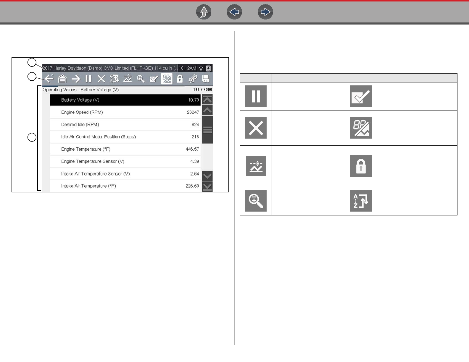
4.2 Features and Icons
4.2.1 Scanner Features
1— Title bar—shows active test, vehicle and diagnostic tool status. The Title bar
appears for all functions and displays information only, there are no
selectable items. See Title Bar on page 7.
2— Toolbar—contains control icons
3— Main body—displays menus, code results, PIDs, etc.
Figure 4-1 Scanner screen features
4.2.2 Scanner Control Icons
The scanner toolbar contains control icons. Control icons may vary depending on the
active function or test. An inverted (highlighted) icon indicates it is selected. Other
control icons (not shown) are described in Common Toolbar Control Icons on page 8.
Icon Function Icon Function
Pause - Indicates PID data
from the motorcycle is being
displayed. Selecting pauses
data collection.
Clear - Erases all the PID
data in the buffer and begins
a new recording. Selecting
opens a confirmation
message.
Trigger - Opens a menu that
allows you to set, arm, and
clear threshold values that
automatically trigger PID
data to be saved from buffer
memory to a file.
Zoom - Incrementally
increases and decreases the
scale of the data being
displayed.
Custom Data List - Opens a
menu for selecting which PIDs
display in the list.
Change View - Changes
display options between PID list
or graph displays.
Lock/Unlock - Locks or unlocks
the highlighted parameter.
Locked PIDs move to the top of
the list and do not scroll as you
move through the data.
Sort - Determines the order in
which PIDs are listed on the
screen.
12
Page 21
Scanner Features and Icons
NOTE
NOTE
NOTE
NOTE
NOTE
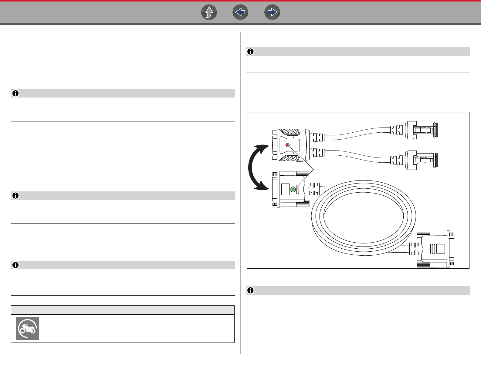
HAR-2
DA-5
(e.g. Harley-Davidson HAR-2)
DA-5 Data Cable
4 and 6 Pin Connectors
(Harley-Davidson Only)
Application Dependent on Model
To Diagnostic Tool
(LED) Power Indicator
(see Note below)
4.2.3 Basic Scanner Operation (Quick Start)
This section lists the basic scanner operation steps, and is only intended as a
quick-start reference. Refer to the supporting topics in this section for detailed
operation information.
z Getting Started (Basic Steps)
Menus, options and procedures will vary across motorcycle manufacturers
and models.
1. Select Scanner from the Home screen.
2. Follow the prompts to identify the motorcycle (e.g. make, year, model), then
select OK to confirm.
3. Follow the onscreen instructions to connect the DA-5 data cable and Smart
Vehicle Interface (SVI) to the motorcycle diagnostic connector. See Data
Cable Connection on page 13.
4. Turn the ignition on and move the “run” switch to on, or start the engine.
Ensure the LEDs on the SVI and DA-5 cables are on when establishing
communication between the motorcycle and diagnostic tool.
4.2.4 Data Cable Connection
On-screen data cable connection instructions ar e provided.
As an example, Figure 4-2 shows a typical data cable connection using the supplied
DA-5 data cable and the Harley-Davidson HAR-2 Smart Vehicle Interface (SVI),
other manufacturers are similar.
Smart Vehicle Interface (SVI)
To Motorcycle Diagnostic Connector
5. Follow the prompts to select a System (e.g. Engine, ABS, Radio).
6. Select a Function/Test (e.g. Codes Menu, Code Scan, Data Display,
Functional Tests). See System Main Menu Options on page 16.
When the diagnostic tool is communicating with a motorcycle an icon is
displayed in the title bar.
Icon Function
Indicates active Scanner communication (displayed in title bar)
Figure 4-2
Contact your sales representative to pur chase add itional Smar t Vehicle
Adapters (SVIs) for other Motorcycle manufacturers.
1. Follow the onscreen instructions to connect the Smart Vehicle Interface (SVI)
to the motorcycle diagnostic connector.
13
Page 22

Scanner Features and Icons
NOTE
NOTE
NOTE
A menu option may be displayed to choose either Automatic ID or Manual ID.
The SVI requires 12VDC power to communicate. Power is nor mally supplied
through the motorcycle diagnostic connector, however the supplied 12VDC
power accessory cable (not shown) can be used when power is needed. When
the LED is on, the SVI is being powered.
2. Connect the DA-5 data cable to the SVI and diagnostic tool.
Ensure the LEDs on the SVI and DA-5 cables are on when establishing
communication between the motorcycle and diagnostic tool.
4.2.5 Vehicle Identification / System Selection
The motorcycle must be correctly identified for the diagnostic tool to communicate,
and display data correctly. Menus and navigation will vary by make and model.
Depending on the motorcycle, the identification process may require manual entry of
the motorcycle information, or it may be automated. The following Scanner functions
are available to identify the motorcycle:
Auto ID - Automatically completes the identification process after the motorcycle
make and year are manually entered.
- Selecting Automatic ID (If supported) will briefly display a
communications screen informing you that the diagnostic tool is
attempting to establish communication and determine vehicle
identification.
Once the vehicle has been identified, the vehicle confirmation screen
displays. If the vehicle information is correct, select OK to continue, then
proceed to step 3.
If the vehicle does not support Auto ID, the diagnostic tool will attempt to
identify the vehicle and then display a message indicating that vehicle
identification cannot be made. If this occurs, proceed to “Selecting
Manual ID” next.
- Selecting Manual ID allows you to manually enter all the vehicle
information to identify the vehicle.
Follow the screen prompts to enter all the information required to identify
the vehicle. Once the vehicle has been identified, the vehicle
confirmation screen displays (Figure 4-3). If the vehicle information is
correct, select OK to continue, then proceed to step 3.
Manual ID - Allows for manual entry of all required motorcycle identification criteria.
z Use the following procedure to identify a motorcycle.
The following procedure applies to most motorcycles, and may vary
depending on the motorcycle. Not all motorcycles support the Auto ID feature.
1. Select Scanner from the Home screen.
2. Follow the prompts to identify the motorcycle (e.g. make, year, model).
Figure 4-3 confirmation screen
After the motorcycle is identified, prompts will indicate to turn the motorcycle
ignition on and connect the data cable.
14
Page 23

Scanner Features and Icons
Depending on the motorcycle, a menu option to select a system list display
type may be provided (Figure 4-4).
Some motorcycles may support a “Fitted Systems” display type. In this
situation a menu option is provided to display the fitted systems or all systems.
Selecting Fitted Systems will only display systems that the diagnostic tool is
communicating with. Selecting All Systems will display every system possibly
supported.
3. A menu of available systems and/or options is displayed. Select a system or
option (Figure 4-5) to continue.
By default, System options are displayed by category (e.g. Audio/Video, Body
Controls, Instruments, etc.). In this mode commonly used selections are a t the
top of the list.
Depending on your preference, select the icon (arrow in Figure 4-5) to toggle
the display between a categorized (Figure 4-5) and non-categorized
(Figure 4-6) list.
When a system (e.g. Engine, Antilock Brakes, etc) is selected, the diagnostic
tool will attempt to establish communication with that motorcycle system, then
(once connected) will display that system’s main menu, see System Main
Menu Options on page 16.
For Code Scan information, see Code Scan on p age 17.
Figure 4-4
Figure 4-5 Typical systems menu (categorized list view)
15
Page 24

Scanner System Main Menu Options
4.3 System Main Menu Options
Once a System is selected (e.g. Engine, Antilock Brakes, etc) is selected, the
diagnostic tool will attempt to establish communication with the motorcycle, then
(once connected) will display (Figure 4-7) the system main menu (available tests).
Figure 4-6 Typical systems menu (non-categorized list view)
Figure 4-7 Typical (Engine) main menu
– Menus and navigation will vary by motorcycle make and model.
The System Main Menu may include these typical selections:
• Codes—displays diagnostic trouble code (DTC) records from the control
modules. Selecting may open a submenu of viewing options. See Viewing
Codes on page 17.
• Clear Codes—erases DTC records and other data from the ECM. This
selection is found on a Codes submenu for some models. See Clear Codes on
page 17.
• Data— displays PID data from the control modules. Selecting may open a
submenu of viewing options. See Viewing and Saving Data on p age 20.
• Functional Tests—provides specific subsystem tests. The tests vary
depending on the manufacturer and model. See Functional Tests on page 30.
• ECU ID—provides specific ECU information for the selected module.
16
Page 25

Scanner Codes - View / Scan / Save
IMPORTANT
IMPORTANT
4.4 Codes - View / Scan / Save
4.4.1 Viewing Codes
After selecting a System, “Codes” may appear as a menu selection (Figure 4-7) from
the Main System Menu. Depending on the motorcycle manufacturer, a di ffe r ent nam e
may be used (e.g. Codes Menu, Codes Only, Codes (No Data), Service Codes, etc).
Selecting this function opens a list of diagnostic trouble codes (DTCs) stored in the
selected control module. The code list includes the DTC and a brief description
(Figure 4-8).
Figure 4-8 DTC results
Select the code or the Extended DTC Data icon (Figure 4-8) for additional
information.The Extended DTC Data icon only displays if the motorcycle supports
this feature and information is available.
4.4.2 Clear Codes
The diagnostic tool can clear codes from the electronic control module(s). This
selection only displays if the motorcycle supports this feature.
z To clear codes:
1. Select Clear Codes from the Codes Menu.
A confirmation message displays.
2. Make sure any conditions shown on the confirmation message are met, then
select Yes.
A “codes cleared” message displays once the operation is complete.
3. Select Continue to return to the Codes Menu.
Clearing codes erases all temporary ECM information. Make sure no vital
diagnostic information will be lost before clearing codes.
4.4.3 Code Scan
Code Scan is available from the Main System Menu, and when selected it scans the
control modules for codes. The results of the scan are configured into a report that is
accessible and printable using ShopStream Connect™. The report can be printed,
downloaded, attached to an e-mail or other social media app to share with others. For
additional information on using ShopStream Connect, see ShopStream Connect ™
on page 50.
Extended DTC Data may include:
• Odometer Mileage
• Occurrence
• Trips Since First Failure
• Trips Since Last Failure
PRE / POST Scan Importance - As many systems do not turn on the
check engine light or other indicator, performing a code scan before
making any repairs may help in troubleshooting, by identifying possible
unknown issues that may be related to the present symptoms.
Performing pre and post scans also allows you to r ecord in report format
the pre-condition of the vehicle and compare the post scan after work is
complete to confirm the repairs were completed properly.
17
Page 26

Scanner Codes - View / Scan / Save
NOTES
Code Scan Toolbar
The Code Scan function and results are dependent upon the vehicle. Not all
vehicles may support this function.
Selecting Code Scan from the Vehicle System menu (Figure 4-9) starts an active
scan of vehicle control modules, and opens the Code Scan results screen
(Figure 4-10).
Figure 4-9 Code Scan
When initially started, progress status is shown at the top indicating the active
scanning progress. Once completed, code results are displayed by system.
The following are displayed as the modules are scanned and are described in the
following sections.
• Code Scan Toolbar
• Total Number of Systems (modules) Analyzed
• List of All the Systems Analyzed with DTCs Totals
The following Code Scan related control icons are used:
Icon Function
Refresh - Refreshes the code scan data (restarts the code scan)
System - Opens the main menu of the system selected (highlighted)
Save - Saves the code scan results as an (.XML) file. See
and Code Scan Results on page 33
.
Viewing Codes
Total Number of Systems (modules) Analyzed
The total number of systems analyzed is actively displayed at the top of the screen as
they are scanned.
Figure 4-10 Code Scan systems analyzed result total
18
Page 27

Scanner Codes - View / Scan / Save
List of All the Systems Analyzed with DTCs Totals
A categorized system list with DTC totals is displayed in the order they are scanned.
To view the main menu for a system in the list, select the system, then select the
System icon (Figure 4-11).
Saving Codes and Code Scan Results
Icon Function
Save - Saves the displayed code list results as an (.XML) file.
When using the code scan feature, or when viewing individual system codes (e.g.
engine, antilock brakes) selecting the Save icon from the toolbar saves the results as
a report formatted file.
To manually save the c ode sca n report:
1. Perform a code scan.
2. After the code scan has completed, select Save.
A confirmation message is displayed indicating that the file was saved.
Message Example: “Saving A2810005.XML”
The saved file(s) can be viewed on the diagnostic tool - See Viewing Codes and
Code Scan Reports on the Diagnostic Tool on page 33.
Printing Codes and Code Scan Results
The code scan report and saved codes can be printed using ShopStream Connect -
See Printing the Code Scan Report on pa ge 53.
Figure 4-11 System icon (opens Main Menu)
Clear All Codes Read by Code Scan
Selecting Clear All Codes Read by Code Scan erases all DTCs from all vehicle
system modules that were read by Code Scan.
19
Page 28

Scanner Viewing and Saving Data
4.5 Viewing and Saving Data
Selecting Data or other similar data menu option (depending on the vehicle
manufacturer) displays PID data for the selected system (Figure 4-12).
4.5.1 About the Data Buffer
The diagnostic tool has the capability to collect, store and save PID data utilizing
internal storage memory and buffer memory.
When Data is displayed onscreen, a data buffer automatically starts to store it in
buffer memory. The data buffer runs continuously (storing data) until the Pause,
Clear, or Save icon is selected.
Buffer memory is limited to a predetermined “total” size. When buffer memory
reaches it’s full capacity, the data buffer will continue to store new data, however
earlier stored data will be removed to allow room for the new data being stored.
The most recent data is always available for review when Pause is pressed, and can
be reviewed using the toolbar controls.
The Data Buffer Indicator (Figure 4-13 left arrow) can be used to visually see the
amount of stored buffer data. This graphical indicator uses a bar graph to show how
much stored data is in the memory buffer.
Figure 4-12 Data display (PID List view)
During data display the main body of the screen is divided into two columns; the lefthand column has a description of the parameter and the right-hand column shows
the current parameter value or state. PIDs are listed in the order in which they are
transmitted by the ECM, so variations between years, makes, and models will occur.
The toolbar control icons are described in Scanner Control Icons on page 12 and
Common Toolbar Control Icons on page 8.
Figure 4-13
The Data Buffer Position Counter (Figure 4-13 right arrow) indicates:
– first value = the numerical position of the current frame of data (displayed)
within buffer memory
– second value = indicates the maximum data buffer size value (e.g. 4000)
During data review (Figure 4-14), a slider on the bar graph indicates the position of
the current frame of data (displayed) in relation to the entire memory buffer contents.
Figure 4-14
20
Page 29

Scanner Viewing and Saving Data
4.5.2 About Cursors
Vertical cursors are automatically displayed (in graphical PID views) to mark specific
data reference points.
Gray (Pause/Save) - If you select Pause or Save while collecting data, a vertical gray
cursor is automatically placed at that point in the data to indicate where the data was
paused or saved.
• Each time Pause is pressed an additional cursor is added, and appears when
Record is pressed to resume data collection.
• Each time Save is pressed an additional cursor is added, and appears when
the data starts again after a slight pause to save the file.
• Cursors are displayed in all PIDs as reference markers.
• Cursors are retained and appear in saved data files.
Blue (Current Position) - If you select Pause while collecting data, a vertical blue
cursor is displayed as an indicator to your position in the data and is denoted by the
current position value in the counter display.
• Cursors are displayed in all PIDs as reference markers.
• Depending on the amount of data saved the blue cursor may be initially located
on the far left next to the description, or the far right next to the scroll bar making
it difficult to see. If this happens, use the control icons (Step/Skip) to move the
data until you can see the cursor.
4.5.3 Pausing and Reviewing Active Data
During normal operation, data from the vehicle’s ECM is continuously being stored in
buffer memory as it is displayed onscreen. The Pause icon, allows you to temporarily
pause data collection to review it in detail.
z To pause and review active data:
While collecting data, select the Pause icon (Figure 4-15).
Red (Triggered PID Activation Point) - When using triggers, a vertical red cursor is
displayed in the data of the triggered PID at the point where the trigger was activated.
• When multiple PIDs are armed, only the PID that is triggered first will display a
red cursor.
Green (Trigger Activation Reference Point) - When using triggers, green vertical
cursors are displayed in all PIDs (except the PID that was triggered) as reference to
the triggered PID activation point.
• When a trigger is activated the displayed red and green cursors are all vertically
aligned in the graphed data to show the relationship of the trigger point in all
PIDs.
Figure 4-15
21
Page 30

Scanner Viewing and Saving Data
NOTE
Toolbar control icons are described in Scanner Control Icons on page 12 and
Common Toolbar Control Icons on page 8.
After Pause is pressed:
• Review control icons are displayed in the toolbar (Figure 4-16). Use th e control
icons to accurately move through the data and position the blue cursor.
• The blue (vertical cursor) (Figure 4-16) indicates your position in the data and
is denoted by the current position value in the counter display. This cursor
displays in all PIDs.
z To resume data collection (after pausing):
• Select the Record icon .
The screen changes back to display data (Figure 4-17).
A vertical gray cursor is displayed on all PIDs, indicating where the data was
paused (Figure 4-17).
Figure 4-16
The Shortcut icon can be set to perform the Pause/Play function. See
Configure Shortcut Button on page 37 for additional information.
Figure 4-17
22
Page 31

Scanner Viewing and Saving Data
NOTE
4.5.4 Saving Data Files
Saving data is useful when trying to isolate an intermittent problem or to verify a
repair. During normal operation, data from the vehicle’s ECM is continuously being
stored in buffer memory as it is displayed onscreen. Selecting Save writes stored
buffer memory to a file.
The Save icon performs the same function as “Save Mo vie” functio n choice
for the programmable Shortcut button, see Configure Shortcut Button on
page 37 for details.
z To save data:
While capturing or reviewing data, select the Save icon.
An onscreen message is displayed to indicate the data file is being saved
(Figure 4-18).
Depending on the amount of data saved the cursor may be initially located on
the far left next to the description, or the far right next to the scroll bar making
it difficult to see. If this happens, use the control icons to move the data until
you can see the cursor.
Figure 4-18 Save dialog box
z To view saved data (on the diagnostic tool):
The saved file can be viewed by selecting Previous Vehicles and Data >
View Saved Data. See View Saved Data on pa ge 33 for basic navigation.
1. Select the desired data file (.SCM file extension).
2. Change the view type and zoom levels as needed.
3. In graph view, use the control icons to move through the data (Figure 4-19).
Toolbar control icons are described in Scanner Control Icons on page 12 and
Common Toolbar Control Icons on page 8.
The blue (vertical cursor) (Figure 4-19) indicates your position in the data and
is denoted by the current position value (Figure 4-19) in the counter display.
The cursor displays in all PIDs.
Figure 4-19
23
Page 32

Scanner Viewing and Saving Data
Pressing the Save icon more than once in the same data collection session will
create multiple (.SCM) files. Each file will contain gray (vertical cursors)
(Figure 4-19) indicating where the data was paused.
4.5.5 Using Zoom
The zoom function allows you to change the magnification level of the
graphed data during data collection and review. Changing magnification
levels allows you to compress or expand the displayed data to quickly
find glitches, or signal losses.
When the Zoom icon is selected the dropdown menu allows you to select the display
magnification level from a range of -2X to +8X. The "Zoom Out" option displays up to
half of the maximum amount of data that can be collected, on one screen. The default
magnification level is 1x.
Examples: Top (+4X), Middle (1X), Bottom (Zoom Out)
Figure 4-20
z To view saved data (on a PC)
Saved data files can also be downloaded to a personal computer (PC) using the Mini
USB jack. Once connected to the PC, the data files can be printed, transferred, and
copied using ShopStream Connect. ShopStream Connect is an application that
creates an interface between the diagnostic tool and a PC. The ShopStream Connect
application is available free online, see ShopStream Connect ™ on page 50.
Figure 4-21 Zoom examples
24
Page 33

Scanner Viewing and Saving Data
4.5.6 Changing Data Views - PID List / Graphs
Selecting the View icon (Figure 4-22) opens a drop-down menu of
viewing options:
• PID List
• 1 Graph
• 2 Graphs
• 4 Graphs
The PID List view is a 2-column display with the name of the parameters in the left
column and their current values in the right column (Figure 4-22).
The 1, 2, and 4 Graph views divide the screen horizontally to simultaneously display
data graphs for the indicated number of parameters (Figure 4-23).
Figure 4-22 PID List view
Figure 4-23 Four graph view
In graph view the text block (Figure 4-24) to the left of the graph displays:
• Top - PID description
• Middle - Current value or state
• Bottom - Active minimum and maximum values
Figure 4-24
25
Page 34

Scanner Viewing and Saving Data
NOTE
4.5.7 Selecting PIDs to Display (custom display)
The Custom Data List icon on the toolbar is used to select which PIDs
to display. Minimizing the number of PIDS displayed allows you to focus
on any suspicious or symptom-specific data parameters. You can add or
remove most PIDs from the list, as certain vital PIDs may not be
removed. These appear in gray at the top of the list along with a lock icon, and they
cannot be selected.
Limiting the number of parameters that display to those that apply to a
particular situation results in a faster data refresh rate, and reduces the
amount of memory used for saved files.
z To create a custom data list:
1. Select the Custom Data List icon on the toolbar.
The data selection screen displays (Figure 4-25) and selection icons appear.
Check marks to the left of the parameter description indicate which parameters
are selected for display.
The toolbar icons provide options for selecting and deselecting parameters to
include or remove from the custom data list:
Icon Description
Select/Deselect - hide or display individual PIDs in the list
Select All/Deselect All - hide or display all PIDs in the list.
2. Create a custom data list by selecting (check mark) the parameters to include.
3. Select Back to display the updated data list.
4.5.8 Locking PIDs (to always display at top)
Use the Lock/Unlock icon to hold selected lines of the data in place and
prevent them from scrolling, or to release previously locked lines of data.
Up to three lines of data may be held at a time. This feature allows you
to position related parameters together, making it easier to monitor their
values and spot inconsistencies.
Locked parameters display as the top frames on the main body of the display screen,
as well as at their usual position within the data list (Figure4-26). A lock ico n a ppears
to the left of the parameter name to indicate it is locked.
z To lock parameters:
1. Highlight the parameter to be locked.
2. Select the Lock/Unlock icon on the toolbar to lock it.
A copy of the locked parameter is now shown at the top of the data list, and a
lock icon appears alongside the parameter name.
3. Highlight and select additional parameters to lock.
Figure 4-25 Data custom PID selection
26
Page 35

Scanner Viewing and Saving Data
NOTE
Up to three parameters can be locked at a time. Once locked, a parameter
remains locked until it is manually unlocked, or communication with the vehicle
is stopped.
4.5.9 Using Triggers
Trigger Description and Features
Setting PID triggers allows you to configure the diagnostic tool to
automatically save PID data to a file, when a PID value meets an upper/
lower limit (trigger point).
When a PID value meets the trigger point it activates the trigger which
captures a short recording of all available PID data and saves it as a data file.
You can review the saved data file to closely evaluate not only the PID that triggered
the event, but all the PIDs being monitored to collectively see what was happening at
the time of the event.
Examples of the following trigger states (Armed / Not Activated - upper image) and
(Activated - lower image) are shown in (Figure 4-27).
Figure 4-26 Locked parameters
If three parameters are locked, one of them must first be unlo cked before
another parameter can be locked.
z To unlock parameters:
1. Scroll through the data list and highlight the parameter to be unlocked, or
released.
2. Select the Lock/Unlock icon on the toolbar.
The released parameter and the lock icon disappear from the list at the top of
the data list.
3. Repeat Step 1 and Step 2 to release other parameters if needed.
27
Page 36

Scanner Viewing and Saving Data
6
1
5
2
7
43
z Setting triggers:
To use triggers, they must be turned on (set/configured), and then armed. Use the
following procedures to setup PID triggers.
1. Highlight the PID to setup with a trigger.
2. Select the Trigger icon.
Selecting the Trigger icon (Figure 4-28) displays trigger menu options:
- Set Trigger—opens setup screen for upper/lower limits (trigger points)
- Arm Trigger—arms the trigger to capture data
- Clear All Triggers—deletes all previously set triggers
Figure 4-27
1— Armed PID Trigger Indicator - A blue outlined flag indicates the PID trigger
is armed.
2— Upper and Lower Limit Lines (Armed) - Colored limit lines indicate the
trigger is armed but not activated.
3— Trigger Activation Point Reference Cursor - Green cursors lines are
displayed on all the other PID graphs to indicate their relationship to where
the trigger occurred.
4— Pause Cursor - A vertical gray cursor line is displayed (all PIDs) as a marker
in the where the data was paused and the file was saved.
5— Activated PID Trigger Indicator - A red flag indicates the PID trigger has
activated.
6— Trigger Activation Point Cursor - A red cursor line is displayed in the PID
data where the trigger was activated.
7— Upper and Lower Limit Lines (Not Armed and Activated) - Gray limit lines
are displayed when the trigger is armed but not activated and after the trigger
has been activated.
Figure 4-28 Trigger menu
If triggers are already set, the menu options are:
- Clear Trigger—deletes the highlighted trigger
- Disarm Trigger—disarms the highlighted trigger
- Clear All Triggers—deletes all set triggers
3. Select Set Trigger.
A graph of the highlighted PID and setup icons display (Figure 4-29).
The upper trigger point must be set first. A red horizontal line is displayed
across the data graph (Figure 4-29) representing the upper trigger point.
4. Use the plus (+) and minus (–) icons (Figure 4-29), or the up b and down d
arrow buttons to change the position of the upper trigger point.
5. Select a, or press the Y/a button, to set the upper trigger point.
28
Page 37

Scanner Viewing and Saving Data
NOTE
The display returns to the PID data view and the trigger points appear as horizontal
lines across the designated graph (Figure 4-31). Repeat this procedure to establish
trigger points for other parameters (up to three) if desired.
Only three parameters can have trigger levels set at one tim e, but only one of
the conditions needs to be satisfied for triggering to occur.
Figure 4-29 Trigger setup - upper limit
The upper trigger line changes color to gray and the lower trigger line displays
in red (Figure 4-30).
6. Change the position of the lower trigger line in the same manner as the upper.
7. When finished, select a, or press the Y/a button, to set the lower trigger level.
Figure 4-31 Trigger set (not armed)
z Arming triggers:
1. Select the Trigger icon.
2. Select Arm Triggers.
The trigger point lines change color to indicate an armed condition
(Figure 4-32).
All set PID triggers are armed simultaneously (if more that one is set). Once armed it
remains armed until you clear it or the trigger is activated.
Figure 4-30 Trigger setup - lower limit
Figure 4-32 Trigger armed
29
Page 38

Scanner Functional Tests
About Activated Triggers
A trigger is activated when a PID value meets an upper/lower limit (trigger point).
When a trigger is activated:
• Data collection is briefly paused as the Scanner captures a recording of all
available PID data, and saves it as a data file.
• A gray cursor line is displayed to indicate the point at which the data was
paused or saved.
• An audible alarm is sounded
• A message displays indicating a data file was saved.
• Data collection continues.
• The activated PID trigger is disarmed.
• A red cursor line is displayed on the graph of the PID with the activated trigger
to indicate where the trigger occurred. A green cursor line is displayed on all the
other PID graphs to indicate their relationship to where the trigger occurred.
4.6 Functional Tests
The Functional Tests selection is used to access OEM model specific subsystem
tests. Available tests vary by manufacturer, year, and model. Only the tests supported
by the motorcycle are displayed in the menu.
Typical functional tests:
• Information Tests—read-only tests (e.g. displaying serial or identification
numbers)
• Toggle Tests—switch a component, such as a solenoid, relay, or switch,
between two operating states.
• Variable Control Tests—command a certain value for a system or component.
• Reset Tests—reset adaptive or learned values
• Scripted Tests—these tests are software routines that place the vehicle into
special operating modes for performing certain repairs, such as bleeding
brakes with ABS.
Selecting Functional Tests opens a menu of test options that varies by make, year,
and model. Selecting a menu option either activates the test or opens a submenu of
additional choices. Follow all screen instructions while performing tests. How and
what information is presented on the screen varies according to the type of test being
performed and the vehicle being serviced.
Figure 4-33 Trigger activated
Figure 4-34 (Typical) Functional test menu
Toggle and variable control tests often display functional test controls on the toolbar
at the top of the screen with PID data in the main body.
30
Page 39

Scanner Functional Tests
Figure 4-35 Functional test example
A Test icon on the toolbar activates the test, and a Return, or similarly named, icon
cancels the test. For variable control tests, the variable value displays between the
main body and the toolbar. Plus and Minus icons on the toolbar increase and
decrease the variable value.
A Data List icon, shown to the left, is available on the toolbar for some tests.
This feature allows you to change which data list displays in the main body
without exiting the functional test. The icon is only available when the test
is inactive.
31
Page 40

Section 5 Previous Vehicles and Data
This section describes the basic operation of the Previous Vehicles and Data
function.
The Previous Vehicles and Data icon is located on the Home
screen. This function allows you to select recently tested
motorcycles and access saved data files.
Main Topic Links
• Vehicle History page 32
• View Saved Data page 33
• Viewing Codes and Code Scan Results page 33
• Delete Saved Data page 35
Figure 5-1 Vehicle history list
5.1 Previous Vehicles and Data Menu
The following options are available from the Previous Vehicles and Data menu:
• Vehicle History
• View Saved Data on page 33
• Delete Saved Data on page 35
5.1.1 Vehicle History
The diagnostic tool stores the identification of the last twenty-five motorcycles
tested, so there is no need to go through the complete identification sequence when
performing a retest after repairs have been made. The oldest record is deleted
when a new vehicle is identified once there are twenty-five vehicles on file.
z To select from the vehicle History:
1. Select Previous Vehicles and Data from the Home screen.
2. Select Vehicle History from the menu.
A list of up to 25 previously tested motorcycles displays. Each record is given
a unique file name. Scroll to view the entire list.
3. With the item to be opened highlighted, either select it or press the Y/a button.
The vehicle confirmation screen displays.
4. Select OK or press the Y/a button to continue.
32
Page 41

Previous Vehicles and Data Previous Vehicles and Data Menu
NOTE
5.1.2 View Saved Data
Selecting the View Saved Data menu option opens a list of all the saved data
(movie) files and screen images that are stored in memory. Saved files are listed in
chronological order by the date and time that they were created with the most
recent files are at the top of the list.
z To review a saved data file or image:
1. Select Previous Vehicles and Data from the Home screen.
2. Select View Saved Data from the menu.
3. Select a file to review from the list.
5.1.3 Viewing Codes and Code Scan Results
When code scan or single system code results are saved, they are saved in (.XML)
file format (Figure 5-3).
Figure 5-2 Saved data list
Selecting a file from the list, opens the file.
Saved data files can also be downloaded to a personal computer (PC) using the
Mini USB jack. Once connected to the PC, the data files can be printed, transferred,
and copied using ShopStream Connect. ShopStream Connect is a PC application
that creates an interface between the diagnostic tool and a PC. See ShopStream
Connect ™ on page 50.
To connect to a PC, see Connect-to-PC (File Transfer) on page 37.
A maximum of 50 files are displayed. T o view all (if more than 50) files stored,
transfer the files to a PC and use ShopS trea m Connect. See Connect-to-PC
(File Transfer) on page 37 for additional information.
Figure 5-3 Typical - Code Results (.XML) file
Viewing Codes and Code Scan Reports on the Diagnostic Tool
Once saved, the code scan report can be viewed on the diagnostic tool in the same
manner it was displayed originally.
To view saved codes and cod e scan r eport on the diagno stic tool:
1. Select Previous Vehicles and Data from the Home screen.
2. Select View Saved Data.
3. Select the code scan report .XML file from the list to view the file (Figure 5-3).
33
Page 42

Previous Vehicles and Data Previous Vehicles and Data Menu
Selecting a system code or a code scan .XML file from the saved file list, opens that
file onscreen (Figure 5-4).
Viewing / Printing the Code Scan Report
Once saved, the code scan report can be viewed and printed using ShopStream
Connect, see Printing the Code Scan Repo rt on p age 53.
Figure 5-4 Typical - Code Scan Results (.XML file) viewed onscreen
Figure 5-5 Typical - (Engine System) Code Results (.XML file) viewed onscreen
34
Page 43

Previous Vehicles and Data Previous Vehicles and Data Menu
1 2
3
5.1.4 Delete Saved Data
This menu option is used to permanently erase saved files from memory.
z To delete a saved file:
1. Select Previous Vehicles and Data > Delete Saved Data.
The list of saved files displays.
Select the file(s) to be deleted using the checkboxes.
Use the Select All / Deselect All icon as necessary.
1— Select All / Deselect All Icon
2— Delete Icon
3— Selected files to be deleted
Figure 5-6
2. The files with checkboxes will be deleted. To delete the files select the Delete
icon.
3. A confirmation message displays. Select an option:
– OK—permanently deletes the selected file
– Cancel—returns to the saved files list without deleting the selected file.
35
Page 44

Section 6 Tools
This section describes the basic operation of the Tools function.
The Tools icon is located on the Home screen. This function allows
you to configure diagnostic tool settings to your preferences.
Main Topic Links
• Connect-to-PC (File Transfer) page 37
• Configure Shortcut Button page 37
• System Information page 37
• Settings page 38
– Configure Wi-Fi page 42
– Configuring Scanner page 42
– Configure Units page 43
– High Contrast Toolbar page 39
– Brightness page 38
– Color Theme page 39
– Font Type page 40
– Backlight Time page 40
– Touch Screen Calibration page 40
– Time Zone page 41
– Clock Settings page 41
– Daylight Savings Time page 42
– Time Format page 42
– Date Format page 42
6.1 Tools Menu
The following options are available from the Tools menu:
• Connect-to-PC (File Transfer)—use to transfer and share files with a personal
computer (PC)
• Configure Shortcut Button on page 37—use to change the function of the
shortcut button
• System Information on page 37—use to view configuration information for the
diagnostic tool
• Settings on page 38—use to configure certain characteristics of the diagnostic
tool
Figure 6-1 Tools menu
36
Page 45

Tools Too ls M e nu
3/15/2019 11:01PM
P1000
Bundle: 19.2 Version: 1.5.0.16300 NA
RUNTIME: 5.3.2.5
Serial Number: 044GEP500004
Wi-Fi:
Firmware: 4.7.8
2019
6.1.1 Connect-to-PC (File Transfer)
Connect-to-PC allows you to transfer saved data files on your diagnostic tool to
your personal computer using a USB cable.
The optional ShopStream Connect™ PC software allows you to view, print and
save data files on your PC. In addition, you can download software updates from
the PC to the diagnostic tool. These features provide an ideal way to manage saved
data files. The ShopStream Connect application is available free online, see
ShopStream Connect ™ on p ag e 50.
z To connect the diagnostic tool to a PC:
1. Select Tools from the Home screen.
2. Select Connect-to-PC.
A screen message displays stating that the diagnostic tool is in Connect-to-PC
mode.
3. Connect the supplied USB cable to the diagnostic tool and then to the PC.
The diagnostic tool, displays as an external drive. Using Windows File
Explorer locate the “USERDATA” folder to find saved screenshots (.BMP),
code files (.XML), and data files (.SCM).
4. When finished, select Exit to return to the Tool menu, and disconnect the USB
cable.
4. Select the Back on the toolbar or press the N/X button to return to the options
menu.
6.1.3 System Information
System Information allows you to view patent information and system information,
such as the software version and serial number of your diagnostic tool.
6.1.2 Configure Shortcut Button
This feature allows you to change the function of the Shortcut button. Options are:
• Brightness—opens the brightness setting screen.
• Save Screen—saves a bitmap image of the visible screen.
• Save Movie—writes PID data from buffer memory to a file for future playback.
• Show Shortcut Menu—opens the menu so you can quickly select from any of
the functions.
• Toggle Record/Pause—programs the Shortcut button to work as the Pause
and Play icons.
z To assign a function to the Shortcut button:
1. Select Tools from the Home screen.
The Tools menu opens.
2. Select Configure Shortcut button from the menu.
3. Select a function from the menu.
Figure 6-2 System information
z To display the System information screen:
1. Select Tools from the Home screen to open the menu.
2. Select System Information from the menu.
The System Information screen displays.
3. Scroll as needed to view all of the data.
4. Select Back on the toolbar or press the N/X button to return to the options
menu.
37
Page 46

Tools Too ls M e nu
6.1.4 Settings
This Tools selection allows you to adjust certain basic diagnostic tool functions to
your personal preferences. Selecting opens an additional menu that offers the
following:
• System Settings - see System Settings on page 38
• Configure Wi-Fi - see Configure Wi-Fi on page 42
• Configure Scanner - see Configuring Scanner on page 42
• Configure Units - see Configure Units on page 43
System Settings
Selecting System Settings opens a menu with three options; Display, Date & Time
and Auto VIN. Selecting either Display or Date & Time opens an additional menu
(see below). Selecting Auto VIN provides the option to turn the Instant Vehicle ID
feature on/off.
Display options include:
• Brightness on page 38—adjusts the intensity of the screen back lighting.
• Color Theme on page 39—changes the background color of the screen display.
• High Contrast T oolbar on page 39—enhances toolbar graphics for poor lighting
conditions.
• Font T y pe on p a ge 40—switches between standard and bold text for better
visibility.
• Backlight Time on page 40—adjusts how long the screen stays on with an idle
diagnostic tool.
• Touch Screen Calibration on page 40—calibrates the touch screen display.
Date & Time options include:
• Time Zone on page 41—sets the internal clock to the local time standard.
• Clock Settings on page 41—sets the time on the internal clock.
• Daylight Savings Time on page 42—configures the clock for Daylight Savings
Time.
• Time Format on page 42—switches the time displays between a 12 or 24 hour
clock.
• Date Format on page 42—configures how the month, date, and year displays.
DISPLA Y (setting s)
Brightness
Selecting this option opens the brightness setting screen for adjusting the back
lighting of the display (Figure 6-3).
Figure 6-3 Brightness setting
Each push of the Plus and Minus icons, or the up (b) and down (d) arrows,
incrementally changes the back lighting up or down respectively.
Select Back from the toolbar or press the N/X button to exit.
38
Page 47

Tools Too ls M e nu
Color Theme
This option allows you to select between a white and black background for the
screen. The black background can be beneficial when working under poor lighting
conditions.
Figure 6-4 Night Theme
High Contrast Toolbar
This option allows you to switch to a high contrast toolbar. This toolbar features
black and white icons with crisp graphics that are easier to see in poor lighting
conditions or bright sunlight.
Figure 6-5 High-contrast toolbar
Selecting opens a menu with two choices: Day Theme (white background) and
Night Theme (black background). Make a selection and a “please wait” message
momentarily displays followed by the Home screen. The new toolbar setting is now
active.
Selecting opens a menu with two choices; Color Toolbar and High Contrast Toolbar.
Select and a “please wait” message displays followed by the Home screen. The
new setting is now active.
39
Page 48

Tools Too ls M e nu
IMPORTANT
Font Type
This option allows you to select between standard and bold faced type for the
display screen. Bold type makes screen writing more legible under poor lighting or
bright sunlight conditions.
Selecting opens a menu with two choices: Normal Font and Bold Font. Select a
menu item or scroll and then press the Y/a button to make a selection. The change
is instantaneous. Select the Back or Home icon on the toolbar to return to either the
Settings menu or the Home screen.
Touch Screen Calibration
Calibrating the touch screen maintains the accuracy of the touch-sensitive display.
To avoid serious da mage to t he diagnos tic tool, alwa ys complet e the
touch screen calibration sequence onc e it has begun . Never tu rn of f the
diagnostic tool while a screen calibration is in process.
z To calibrate the touch screen:
1. Select Tools from the Home screen.
2. Select Settings>System Settings>Display>Touch Calibration.
The calibration screen opens (Figure 6-7).
Figure 6-6 Bold Type
Backlight Time
This option allows you to configure how long the screen backlight remains on when
the diagnostic tool is inactive. The following choices are available:
• Always On
• 15 Seconds
• 30 Seconds
• 45 Seconds
• 60 Seconds
Select the menu item desired, or scroll and then press the Y/a button to make a
selection. Select Back or Home on the toolbar to return to either the Settings menu
or the Home screen.
Figure 6-7 Touch screen calibration
3. Select the center of each alignment indicator on the screen as they display in
the corners of the screen, starting in the upper left corner.
4. Once all four indicators have been selected, the verification process starts the
procedure again. Select the center of each alignment indicator when
prompted.
40
Page 49

Tools Too ls M e nu
– If the calibration is successful, the “Touch Calibration Results - Passed”
screen is displayed (Figure 6-8). Press the Y button to complete the process
and return to the Display menu.
– If the calibration is not successful, the “Touch Calibration Results - Failed”
screen is displayed. Press the Y button to perform the procedure again.
The results screen (Figure 6-8) shows the entered calibration of each
indicator. Ideal calibration would be to select each indicator exactly in the
center, however selection inside the di splaye d circle is ac ceptable. If selecting
the center is difficult using your finger, use a touch screen stylus (not included).
z To set the clock:
1. Select Tools from the Home screen to open the menu.
2. Select Settings from the menu.
3. Select Clock Settings from the menu.
A warning message briefly displays followed by the Clock Settings screen
(Figure 6-9).
Figure 6-8 T ouch screen calibration - Passed
DATE & TIME (settings)
Time Zone
This option opens a menu of time zone settings. Scroll to highlight, then select the
local time zone. The display returns to the Settings menu once a time zone is
selected.
Clock Settings
This option opens a window for resetting the time on the real-time clock.
Figure 6-9 Clock settings
4. Select the up (+) icon on the screen or press the up (b) button to incrementally
increase the number in the highlighted field. Select the down (–) icon on the
screen or press the down (d) button to incrementally decrease the number.
5. Select the check (a) icon on the screen or press the Y/a button to move the
highlight to the next field.
6. Repeat Step 4 and Step 5 until the correct time is displayed.
7. Select the Back icon on the toolbar or press the N/X button to close the Clock
Settings window and return to the Settings menu.
41
Page 50

Tools Too ls M e nu
Daylight Savings Time
This option opens a menu to configure the internal clock for Daylight Savings Time.
Choose from:
• ON—sets the clock for Daylight Savings time.
• OFF—sets the clock for standard time.
Make either selection, then select the Back icon or press the N/X button to return to
the menu.
Time Format
This option determines whether time is displayed on a 12 or 24 hour clock.
Selecting opens a menu with two choices:
• 24 Hour Format
• 12 Hour Format
Make either selection, then select the Back icon or press the N/X button to return to
the menu.
Date Format
This option allows you to select how date information is displayed. Select from:
• (MM_DD_YYYY)—Month, Day, Year
• (DD_MM_YYYY)—Day, Month, Year
• (YYYY_MM_DD)—Year, Month, Day
Configuring Scanner
This option allows you to change the scanner display to toggle scales on and off.
Scales are the graduations and values that display on the horizontal axis at the
base of the parameter graphs. The waveform fills the entire graph area with scales
switched off.
Make a selection, then select the Back icon or press the N/X button to return to the
menu.
Configure Wi-Fi
Selecting Configure Wi-Fi allows you to configure and troubleshoot the diagnostic
tool Wi-Fi connection, see Wi-Fi Connection / Troublesho oting on page 44.
Figure 6-10 Scales hidden (upper), displayed (lower)
z To change hide/show scales:
1. Select Tools from the Home screen.
2. Select Settings from the Tools and Setup menu.
3. Select Configure Scanner from the Settings menu.
4. Highlight either menu entry to make a selection:
– Show Graph Scale—to switch the scales on.
– Hide Graph Scale—to switch the scales off.
5. Select the Back icon or press the N/X button to return to the Settings menu.
42
Page 51

Tools Too ls M e nu
Configure Units
Selecting opens a dialog box that allows you to choose between US customary or
metric units of measure for various units.
Figure 6-11 Configure units menu
z To change the units setup:
1. Select Tools from the Home screen to open the menu.
2. Select Configure Units to open the menu.
3. Select an item from the Configure Units menu.
4. Select a setting from the listed choices.
5. Select Back on the toolbar or press the N/X button to return to the options
menu.
43
Page 52

Section 7 Wi-Fi Connection / Troubleshooting
Wi-Fi On Wi-Fi O
Previous Vehicle
and Data
OBD-II/EOBD
Scanner
Tools
The diagnostic tool is equipped Wi-Fi connection capability, however the Wi-Fi
connection is solely dedicated to our Snap-on Web Services Network.
Connecting to Wi-Fi allows the tool to periodically receive messages from Snap-on.
These messages will be displayed to inform you of software updates and upgrades,
as well as other important information.
This section includes information on Wi-Fi connection and troubleshooting.
Main Topic Links
• Checking if Wi-Fi is On/Off page 44
• Checking if Wi-Fi is Connected page 44
• Wi-Fi Icons (Setup) page 45
• Turning Wi-Fi On and Connecting to a Network page 45
• Add Network Advanced (Connecting to a hidden network) page 46
• Wi-Fi Testing page 46
• Wi-Fi Troubleshooting and Status Messages page 47
7.1 Checking if Wi-Fi is On/Off
If the Wi-Fi indicator is displayed in the title bar, Wi-Fi is on. If Wi-Fi is off, see
T urning Wi-Fi On and Connecting to a Network on page 45 to turn it on and
connect.
7.2 Checking if Wi-Fi is Connected
Check the Wi-Fi indicator in the title bar:
Wi-Fi is on and connected to a network (1 to 3 bars).
Wi-Fi is on, but not connected (zero bars). See Wi-Fi Troubleshooting and
Status Messages on page 47
44
.
Page 53

Wi-Fi Connection / Troubleshooting Wi-Fi Icons (Setup)
NOTES
1
2
7.3 Wi-Fi Icons (Setup)
Familiarize yourself with the following Wi-Fi icons and indicators from the Wi-Fi
configuration screen.
Wi-Fi Icon (toggle type) Wi-Fi Test Icon Wi-Fi Signal Strength Indicator
Select to turn
Wi-Fi ON
Displayed on Wi-Fi configuration screen only
Select to turn
Wi-Fi OFF
Select to open
Wi-Fi Test screen
the
Zero bars
indicates no
signal
Displayed on the title bar next to the
battery level indicator
Three bars
indicate full
strength signal
7.4 Turning Wi-Fi On and Connecting to a
Network
1. From the Home screen, select Tools > Settings > Configure Wi-Fi.
2. Select the Wi-Fi icon to turn Wi-Fi on.
Figure 7-1 Wi-Fi Icon (shown off)
3. The Wi-Fi icon will change to , indicating Wi-Fi is on.
Figure 7-2 Wi-Fi Configuration Screen
1— Available Network Connections
2— Wi-Fi Icon (Wi-Fi shown on)
A password is required when choosing a secured (protected) netwo rk. Enter
the password using the on-screen keyboard and then se lect the check ma rk
on the keyboard to continue.
Networks with a proxy , challenge page, or that require the user to accept terms
of usage are not supported.
Wi-Fi performance varies depending on your wireless network equipme nt and
ISP.
The screen will change to display available supported network connections.
4. Select your network. Use the scroll feature to show all active connections
(Figure 7-2).
5. Select Connect to connect to your desired network or Cancel to cancel the
request.
6. From the Connect confirmation screen select OK to continue using this
connection or Forget to disconnect this connection.
• If the status message “Not Connected” is displayed, retry the configuration
process or see “Wi-Fi Testing” on page 46 for additional information.
45
Page 54

Wi-Fi Connection / Troubleshooting Add Network Advanced (Connecting to a hidden network)
7.5 Add Network Advanced (Connecting
to a hidden network)
The Add Network selection allows you to connect to a network that is not
broadcasting its name (not visible in the displayed network list). These networks are
also known as "hidden" networks.
To connect to a hidden network you will first need to know the following:
• Network Security Type
– Open (only need SSID)
– WPA or WPA2 (Pre-shared key)
– WEP (WEP key)
• Network name or SSID (Service Set Identifier)
• Network Password
z Connecting to a Hidden Wi-Fi Network
1. From the Home screen, navigate to Tools > Settings > Configure Wi-Fi.
2. Select Add Network Advanced from the network list (scroll to end of list).
3. Select security type Open, WPA, WPA2, or WEP. Refer to the router user
manual or your IT administrator to determine the type.
4. Enter the network name or SSID
5. Enter the network password.
6. Select Connect at the prompt to connect to the network.
7. Select OK at the confirmation screen to continue using this connection, or
Forget to disconnect this connection.
7.6 Wi-Fi Testing
If you are experiencing network connection issues, an automated testing feature is
available to quickly test your network connection.
z Testing Connections
1. Before you start the automated testing procedure, turn off the diagnostic tool
and then turn it on. This clears previous testing messages from memory.
2. Connect to your desired network, see “Turning Wi-Fi On and Connecting to a
Network” on page 45.
3. From the Wi-Fi configuration screen, select the Wi-Fi Test icon to open the
network connection test screen (Figure 7-3).
Figure 7-3 Wi-Fi T est Icon
The network connection test is an automated test that begins when the screen
is displayed. Network connection systems are tested in sequence and display
a status indicator
(Red = test failed, Yellow = test is process, or Green = test completed
satisfactorily) when finished (Figure 7-4).
Connectivity of the following systems are checked:
• Hardware
• Router
• Internet
• HTTP
• Web Services Network
46
Page 55

Wi-Fi Connection / Troubleshooting Wi-Fi Troubleshooting and Status Messages
2
1
1
2
7.7 Wi-Fi Troubleshooting and Status
Messages
The following troubleshooting information is not inclusive and is meant as a guide
only. Other issues and solutions may arise that are not stated here. The following
description of terms are provided for reference as used in the following
troubleshooting chart:
• Router - The data transmission device directly connected to your ISP.
• Remote Wireless Access Point - A wireless connection device between the
router and your diagnostic tool.
• Wi-Fi Radio - The internal diagnostic tool radio transmitting and receiving Wi-
Fi signals.
• Network Connection - Also called Wi-Fi connection. The configured Wi-Fi
router connection the diagnostic tool connects to. This connection can be
secured (password protected) or unsecured (open).
Figure 7-4 Connection Test s
Router Information
1— Connection Tests
2— View Summary
4. If a connection issue(s) is present, select View Summary to review the results.
The summary information is helpful if you are experiencing difficulties with
your connection (Figure 7-5). Scroll through the summary information to
review the test results for each system and Tip messages for the current
connection issue. See Connection Tests - Troubleshooting chart in “Wi-Fi
Troubleshooting and Status Messages” on page 47 for additional information.
Figure 7-5 View Summary
1— Connection Test Results
2— Connection Issue Tip Message
Router compatibility and setup are important factors to check when trying to
determine connectivity problems. Although we have tested this device at the factory
to verify connectivity, we cannot guaranty its connectivity with your specific
equipment. There may be some situations that require your time for router
connection troubleshooting and/or additional consultation and equipment. Snap-on
Incorporated is not responsible for any costs incurred for any additional equipment,
labor or consultation charges or any other costs that may result from correcting
non-connectivity issues with this device.
47
Page 56

Wi-Fi Connection / Troubleshooting Wi-Fi Troubleshooting and Status Messages
Check Router Settings
Verify the following router settings BEFORE you begin troubleshooting a nonconnectivity or “No Connection” problem. After each check, make any corrections
as necessary then retest for connectivity. Contact your IT administrator or ISP
for assistance.
1. Check your router connection and if applicable, the remote wireless access
point connection.
2. Clear saved Wi-Fi networks, see Clearing Wi-Fi Networks on page 48.
3. Verify:
(a). Router is configured to use Dynamic Host Configuration Protocol
(DHCP), not a static IP address.
(b). Router and/or settings for this device are configured to 2.4GHz. 5GHz is
not supported.
(c). Router is configured to B/G and/or N standard wireless networks to
2 .4GHz. 5GHz is n o t supported. S e e your router "User Guide" for setup,
connection and troubleshooting procedures.
4. Check for router firmware and update to current version, if applicable.
5. Restart or reset the router. See your router "User Guide" for procedures.
6. Connect to a different router.
Clearing Wi-Fi Networks
1. Select the Wi-Fi network that you are trying to connect to from the list of saved
networks on the Wi-Fi configuration menu.
The Wi-Fi Summary page displays.
2. Select FORGET
The Wi-Fi Configuration menu displays.
3. Repeat steps (1) and (2) for ALL saved Wi-Fi networks.
4. Once all saved Wi-Fi networks have been deleted (forgotten) turn off the
diagnostic tool.
5. Turn on the diagnostic tool and connect to the desired Wi-Fi network, see
T urn ing W i-Fi On a nd Conne cting to a Ne twork on page 45.
General -Troubleshooting
Problem Possible Cause Corrective Action
Web Services
are not
available
Wi-Fi
connection
drops off or
disconnects
intermittently
Access may be
temporarily
unavailable
Wi-Fi radio is
turned Off
Not connecting to a
network
Wi-Fi Signal
strength
insufficient
Router overloaded
Try to access at a later time as updates may be in
process.
1. From the Home screen, navigate to Too ls >
Settings > Configure Wi-Fi.
2. Select the Wi-Fi icon and turn the Wi-Fi radio on.
The Wi-Fi icon will change from a green check mark
icon to red "X" mark icon indicating Wi-Fi radio is on.
3. Connect to a known good network.
1. Clear saved Wi-Fi networks, see
Networks on page 48
2. Connect to a network.
3. From the Configure Wi-Fi screen select the
Wi-Fi Test icon and review the results. See
Connection Test s - Troublesho oting in the following
table.
Check Wi-Fi signal strength - out of range or
interference. Move closer (within 50 Ft. (15 M) or into
a direct open sight-line of the router or if applicable,
remote wireless access point. Eliminate interference
from overhead lights, windows, walls, other wireless
devices, metal objects and devices that emit
electrostatic discharge.
Disconnect/disable other Wi-Fi devices connected to
the router.
.
Clearing Wi-Fi
48
Page 57

Wi-Fi Connection / Troubleshooting Wi-Fi Troubleshooting and Status Messages
Connection Tests - Troubleshooting
Possible Cause
Failed Test
Hardware
Router
Internet
HTTP
Web Services
Network
(Displayed Tip
Message*)
Wi-Fi radio not
responding and/or will
not turn off
Wi-Fi radio not
responding and/or will
not initialize
Missing or corrupt
firmware file(s)
This device is not
connected to a router
This device is not
connected to the
Internet or has no DNS
This device cannot
communicate using
HTTP
Web Services may be
temporarily unavailable
or Not connecting to a
network
Corrective Action / Checks
Contact Customer Support for assistance.
Check Wi-Fi signal strength - out of range or
interference. Move closer (within 50 Ft. (15 M) or
into a direct open sight-line of the router or if
applicable, remote wireless access point. Eliminate
interference from overhead lights, windows, walls,
other wireless devices, metal objects and devices
that emit electrostatic discharge.
Check router connection and setup. See
Router Settings on page 48
Check router connection and setup. See
Router Settings on page 48
Domain Name System (DNS) server not
connected. Contact your Internet service provider
(ISP).
Check if your Internet access uses a “Proxy” or
“Accepting terms in a browser” protocol, or uses a
challenge page. These protocols are not supported
by this device. Contact your IT administrator or ISP
for options.
Try to access at a later time as Web Services may
be performing updates to the service.
Check router connection and setup. See
Router Settings on page 48
for procedure.
for procedure.
for procedure.
Check
Check
Check
Wi-Fi Testing on page 46 for additional information.
* See
49
Page 58

Section 8 ShopStream Connect
This device is now in Connect-to-PC mode.
Press to exit.
Exit
Connect-to-PC
™
Introduction
This section provides a brief introduction to the features and operation of
ShopStream Connect (SSC).
SSC is a companion PC application (provided at no charge) that extends the
capabilities of your diagnostic tool, by connecting to your PC.
SSC allows you to:
• Print data files, screenshots and code scan reports
• Download software upgrades and updates to your PC, and then install them on
to your diagnostic tool.
• Transfer data files bi-directionally between your diagnostic tool and your PC.
• View, save and manage your data files on your PC.
• Add or edit notes and comments to your data files.
The ShopStream Connect (SSC) software is available online at:
http://diagnostics.snapon.com/ssc
Complete ShopStream Connect operation instructions can be found in the
ShopStream Connect User Manual, located online at:
http://diagnostics.snapon.com/usermanuals
8.1 Using SSC (Connecting to your PC)
z To connect and use SSC with your diagnostic tool:
1. Download and install SSC on your PC from:
http://diagnostics.snapon.com/ssc
2. Turn your diagnostic tool on.
3. Connect the supplied USB cable from the USB jack on your diagnostic tool to
your PC:
4. From the diagnostic tool Home screen, select Tools > Connect-to-PC.
The “Device is now in Connect-to-PC mode” screen message is displayed
(Figure 8-1) and the ShopStream Connect software will open automatically on your
PC (Figure 8-2).
Main Topic Links
• Using SSC (Connecting to your PC) page 50
• SSC Main Screen page 51
• Scanner DataViewer page 52
• Image Viewer page 52
• Printing the Code Scan Report page 53
• Customizing the Code Scan Report page 54
• Software Upgrades and Updates page 55
Figure 8-1
If the ShopStream Connect software does not open, open it from the Windows Start
menu or use the ShopStream Connect shortcut icon on the Windows desktop
(automatically created during installation).
50
Page 59

ShopStream Connect ™ SSC Main Screen
P1000
8.2 SSC Main Screen
The ShopStream Connect software will open automatically when you connect the
diagnostic tool to your PC USB connection, Using SSC (Connecting to your PC) on
page 50.
The following shows the main screen layout for ShopStream Connect software.
5 6 7
4
3
2
1
5— Tabs—provides access to data files and presets stored on the diagnostic tool
or on the PC, and also allows viewing of software revision details of the
diagnostic tool.
6— Main display—shows stored data files details. NOTE: The files listed are
sortable (ascending/descending) by clicking on the colum n t ab at th e top
(e.g. File Name, T y pe, etc.) Sort pr eference s are saved when the
ShopStream Connect pro gram is closed.
7— Preview—displays a sample of the file if the selected file is a image file.
Figure 8-2
1— Notes Window—allows you add notes to select data files. Select Save from
the menu bar to save your notes. NOTE: Not all file types allow notes, the
Notes window will be grayed out when a file type that does not support notes
is highlighted. Some image files may display notes for reference purposes
(the notes are grayed out and not editable).
2— File directory structure—displays the file directory structure of your PC in
standard Windows format, and shows any connected diagnostic tools at the
bottom of the data list.
3— Data Manager Toolbar—provides control icons that perform a variety of
operations on data files.
4— Main Menu bar—contains File, Edit, Tools, and Help menus.
51
Page 60

ShopStream Connect ™ Scanner DataViewer
NOTE
431 2
8.3 Scanner DataViewer
SSC allows you to view data files recorded with your diagnostic tool, on your PC.
When a Scanner data file is selected, it opens and displays in the Scanner
DataViewer (Figure 8-3). Scanner DataViewer allows you play the data file and
custom configure the data in a number of ways.
1
11
10
2 3
8.4 Image Viewer
SSC allows you to view and print .bmp, .jpg and .sps image files (screenshots) saved
on your diagnostic tool, with your PC.
File extension types vary depending on the diagnostic tool. Not all th e file
4
5
extensions described here may be available on your diagnostic tool.
9
8
1— Menu bar
2— Display toolbar
3— Graph display
4— Properties icon
5— Vertical Scroll bar
Figure 8-3
7
6— Zoom controls
7— Slider bar
8— Navigation toolbar
9— Parameter text list
10—Highlighted PIDs - indicates
graphs currently displayed
11—Parameter configuration tabs
6
52
1— Exit - closes the Image Viewer
2— Print - prints the image
3— Print Preview - allows the image
to be previewed before printing
4— Captured Screen Image
Figure 8-4
Page 61

ShopStream Connect ™ Printing the Code Scan Report
P1000
My printer 1
My printer 2
8.5 Printing the Code Scan Report
To print the Code Scan Report, the saved code scan .XML file must be opened
using ShopStream Connect.
To print the Code Scan Repo rt using ShopStream Connect:
1. Double-click the code scan .XML file from the file list to open the Code Scan
Report (Figure 8-5) in the Code Scan Viewer (Figure 8-6).
Figure 8-6
Figure 8-5
2. Select Print or Print Preview from the Code Scan Viewer menu to print or
preview the report (Figure 8-6).
3. Selecting Print opens the Windows print dialog window (Figure 8-7). Select
your printer from the list, then select Print to print the report.
Figure 8-7
53
Page 62

ShopStream Connect ™ Customizing the Code Scan Report
P1000
8.6 Customizing the Code Scan Report
Select fields of the Code Scan Report can be edited using ShopStream Connect.
To edit the Shop Informat ion (h eader) of the Co de Scan Repo rt:
1. From ShopStream Connect, select Too l s > Options > Edit Shop Info
(Figure 8-8).
Figure 8-8
2. The Shop Info dialog box opens (Figure 8-9) allowing you to enter the name
address, and phone number for your shop. This information is included as a
header on the report.
Figure 8-9
A preview panel at the bottom of the box shows how the information will appear on
a print out (Figure 8-9).
3. Check the “Use Shop Info in Printout Header” box to show the Shop Info in
the printout (Figure 8-9).
4. Check the “Use timestamp in Vehicle System Report” box to show the time
the vehicle was scanned in the printout (Figure 8-9).
5. When you are finished editing, select Save (Figure 8-9) to save the
information and close the dialog box.
54
Page 63

ShopStream Connect ™ Software Upgrades and Updates
NOTE
NOTE
My Diagnostic Tool
(“My Diagnostic Tool”)
(“My Diagnostic Tool”)
(e.g. “My Diagnostic Tool”)
8.7 Software Upgrades and Updates
Upgrade/Update Descriptions:
• Software Upgrade - a software upgrade is a new software version (contact your
sales representative for purchase information).
• Software Update - a software update is a service release for installed software.
These are available free of charge, and are provided as necessary to update
installed software. When your diagnostic tool is connected to a PC using SSC,
the SSC software will automatically check for updates, and if an update is
available, it will provide installation instructions. Follow the screen prompts to
accept, download and install the software.
To receive updates or upgrades, SSC software must be installed on your PC
and have connection to the Internet.
z Example - Updating diagnostic tool software:
1. Select Tools > Update Software > (diagnostic tool type - e.g. P1000) from
the Menu bar (Figure 8-10).
The software checks the Snap-on web server for available updates.
ShopStream Connect will now check for updates for the following:
SOLUSULTRA
Do you wish to continue?
The following update is available for SOLUSULTRA
Version: 3.3.1.11769 [US] Size 38.96 MB
SOLUSULTRA 13.4.1. After update us complete: if direct connected, unplug USB cable - if using Compact Flash(CF)
insert CF and power up the handheld.
To download this update click ‘Download’
Figure 8-11
For additional information on ShopS tream Conn ect software updates and
upgrades, download the ShopStre am Connect User Manual from our website:
http://diagnostics.snapon.com/usermanuals
Figure 8-10
2. If service release updates are available, select Next to continue, then select
Download and follow the on-screen instructions to complete the installation
(Figure 8-11).
55
Page 64

ShopStream Connect ™ Software Upgrades and Updates
IMPORTANT
8.7.1 End User License Agreement
Before software installation at initial purchase, and before all subsequent software
updates/upgrades installations End User License Agreement (EULA) acceptance
is required.
Use of Software is governed by the terms and co nditions of the End User
License Agreement. The diagnostic tool should not be initially operated
until the End User License Agreement is read. Use of the device
acknowledges your acceptance of the End User License Agreement. The
Snap-on Incorporated Software End User Lice nse Ag reement is
available at: https://eula.snapon.com/diagnostics
To Accept: at the screen prompt (Figure 8-12) click the checkbox on the left side of
the window, and then select Agree and Continue. The software will be installed
automatically.
Figure 8-12 below represents a typical EULA acceptance agreement screen.
To Decline: at the screen prompt (Figure 8-12) select I Decline. A confirmation
message is displayed providing options to Go Back or Exit the software installation
(Figure 8-13).
Figure 8-13 Typical E ULA accept ance screen
Figure 8-12 Typical EULA acceptance screen
56
Page 65

Section 9 Maintenance
IMPORTANT
IMPORTANT
This section describes basic cleaning and battery replacement procedures for your
diagnostic tool.
Main Topic Links
• Cleaning and Inspecting the Diagnostic Tool page 57
• Battery Pack Service page 57
• Cleaning the Touch Screen page 57
• Safety page 57
• Ordering a New Battery Pack page 58
• Removing / Installing the Battery Pack page 58
• Disposing of the Battery Pack page 59
9.1 Cleaning and Inspecting the
Diagnostic Tool
Periodically perform the following tasks to keep your diagnostic tool in proper
working order:
• Check the housing, cables and connectors for dirt and damage before a n d after
each use.
• At the end of each work day, wipe the diagnostic tool housing, cables and
connectors clean with a damp cloth.
Do not use any abrasive cleansers or automotive chemica ls on the
diagnostic tool.
9.1.1 Cleaning the Touch Screen
The touch screen can be cleaned with a soft cloth and a mild window cleaner.
Do not use any abrasive cleansers or automotive chemicals on the touch
screen.
9.2 Battery Pack Service
9.2.1 Safety
Follow all safety guidelines when handling the battery pack.
WARN ING
Risk of electric shock.
• Prior to recycling the battery pack, protect exposed terminals with heavy
insulating tape to prevent shorting.
• Disconnect all test leads and turn diagnostic tools off before removing the
battery pack.
• Do not attempt to disassemble the battery or remove any component
projecting from or protecting the battery terminals.
• Do not expose the diagnostic tool or battery pack to rain, snow, or wet
conditions.
• Do not short circuit the battery terminals.
Electric shock can cause injury.
57
Page 66

Maintenance Battery Pack Service
IMPORTANT
NOTE
IMPORTANT
IMPORTANT
9.2.2 Ordering a New Battery Pack
WARN ING
Risk of explosion.
• The Lithium battery is factory replaceable only, incorrect replacement or
tampering with the battery pack may cause an explosion.
Explosion can cause death or serious injury.
If the battery pack needs to be replaced, contact your sales representative to order
a new battery pack.
Only use the recommended Snap-on replacement battery p ack.
The battery pack contains no user servicea ble comp onents . Tampering
with the battery pack terminals or hous ing will void the product warranty .
Keep the following in mind when using and handling the battery pack:
• Do not short circuit battery pack terminals.
• Do not immerse the diagnostic tool or battery pack in water, or allow water to
enter the diagnostic tool or battery pack.
• Do not crush, disassemble, or tamper with the battery pack.
• Do not heat the battery pack to over 100°C (212°F), or dispose of it in a fire.
• Do not expose the battery pack to excessive physical shock or vibration.
• Keep the battery pack out of reach of children.
• Do not use a battery pack that appears to have suffered abuse or damage.
• Charge the battery pack in the appropriate charger only.
• Do not use a battery charger that has been modified or damaged.
• Use the battery pack for the specified product only.
• Store the battery pack in a cool, dry, well ventilated area.
The battery pack should be used within a short period of time (about 30 days)
after charging to prevent loss of cap acity due to self- discharging.
9.2.3 Removing / Installing the Battery Pack
If replacing the battery pack, only use the recommended Snap-on
replacement battery pack.
z To remove the battery pack:
1. Loosen the battery cover screw, until the battery cover is loose from the
housing (Figure 9-1).
2. Remove the battery pack cover.
3. Pull the bottom edge of the battery pack up then tilt it out to remove.
z To install the battery pack:
1. Position the battery pack with the arrows (on the battery pack) facing up
Figure 9-1).
2. Tilt the top of the battery pack in to align the tabs, then down to install into
place.
3. Install the battery pack cover, in the opposite manner as removal, aligning the
tabs and tilting down and in into place.
4. Tighten the battery pack cover screw.
If long-term storage of the battery pack is necessary, it should be stored in a in a
cool, dry, well ventilated place with a 30 to 75 percent state of charge to prevent loss
of characteristics.
To prolong the life of your battery, turn off the diagnostic tool when not in use. The
diagnostic tool has a built in charger that recharges the battery on demand
whenever it is connected to a power source.
58
Page 67

Maintenance Battery Pack Service
IMPORTANT
1
2
3
This side up.
9.2.4 Disposing of the Battery Pack
Always dispose of the battery pack according to local regulations, which vary for
different countries and regions. The battery pack, while non-hazardous waste, does
contain recyclable materials. If shipping is required, ship the battery pack to a
recycling facility in accordance with local, national, and international regulations.
Always dispose of materials according to local regulat ions.
For additional information within the United States of America contact:
• Rechargeable Battery Recycling Corporation (RBRC) at www.call2recycle.org
Phone - 800 822-8837
For additional information within Canada contact:
• Rechargeable Battery Recycling Corporation (RBRC) at www.call2recycle.ca
Phone - 888 224 9764
1— Battery Pack
2— Battery Pack Cover
3— Battery Pack Cover Screw
Figure 9-1
Products bearing the WEEE logo (Figure 9-2) are subject to European Union
regulations.
Figure 9-2 WEEE logo
Contact your sales representative for details.
59
Page 68

Legal Information
IMPORTANT
Trademarks
Snap-on is a trademark registered in the United States and other countries of
Snap-on Incorporated. All other marks are trademarks or registered trademarks of
their respective holders.
Copyright Information
© 2019 Snap-on Incorporated. All rights reserved.
Software License Information
Use of Software is governed by the terms and conditions of the End User License
Agreement. The End User License Agreement is provided with the diagnostic tool
and the device should not be initially operated until the End User License Agreement
is read. Use of the device acknowledges your acceptance of the End User License
Agreement. The Snap-on Incorporated Software License Agreement is available at:
https://eula.snapon.com/diagnostics
Patent Information
For a listing of Snap-on products that are protected by patents in the United States
and elsewhere, visit: https://patents.snapon.com
Disclaimer of Warranties and Limitation of
Liabilities
All pictures and illustrations shown are for reference purposes only. All information,
specifications and illustrations in this manual are based on the latest information
available at the time of printing and are subject to change without notice. While the
authors have taken due care in the preparation of this manual, nothing contained
herein:
• Modifies or alters in any way the standard terms and conditions of the
purchase, lease, or rental agreement under the terms of which the equipment
to which this manual relates was acquired.
• Increases in any way the liability to the customer or to third parties.
Snap-on
Manuals / Technical Documentation - The information in this manual is periodically
revised to ensure the latest information is included. Download the latest version of
this manual and other related technical documentation from the
Snap-on Diagnostics website.
®
reserves the right to make changes at any time without notice.
Before operating or maintaining this unit, please read this manual
carefully paying extra attention to the safet y warnings and prec auti ons.
Manual Application
This manual includes information and images applicable to the diagnostic software
version that was current at the time of publication. Some information within this
manual may not be applicable to later diagnostic software versions.
ZEESC334A Rev. A 25-A-19 NA
60
Page 69

Legal Information FCC Compliance Statement
FCC Compliance Statement
This equipment has been tested and found to comply with the limits for a Class B
digital device, pursuant to part 15 of the FCC rules. These limits are designed to
provide reasonable protection against harmful interference in a residential
installation. This equipment generates, uses and can radiate radio frequency energy
and, if not installed and used in accordance with the instructions, may cause harmful
interference to radio communications. However, there is no guarantee that
interference will not occur in a particular installation. If this equipment does cause
harmful interference to radio or television reception, which can be determined by
turning the equipment off and on, the user is encouraged to try to correct the
interference by one or more of the following measures:
• Reorient or relocate the receiving antenna.
• Increase the separation between the equipment and receiver.
• Connect the equipment into an outlet on a circuit different from that to which the
receiver is connected.
• Consult the dealer or an experienced radio/TV technician for help.
CAUTION
You are cautioned that changes or modi fications not expressly approved by the party
responsible for compliance could void your authority to operate the equipment.
FCC RF Radiation Exposure Statement
1. This transmitter must not be co-located or operating in conjunction with any other
antenna or transmitter.
2. This equipment complies with FCC RF radiation exposure limits set forth for an
uncontrolled environment. This device was tested for typical lap held operations
with the device contacted directly to the human body to the back side of the
Display Unit. To maintain compliance with FCC RF exposure compliance
requirements, avoid direct contact to the transmitting antenna during
transmitting.
3. According to FCC 15.407(e), the device is intended to operate in the frequency
band of 5.15GHz to 5.25GHz under all conditions of normal operation. Normal
operation of this device is restricted to indoor use only to reduce any potential for
harmful interference to co-channel MSS operations.
61
 Loading...