

Page 1
OWNER’S
CE-8.0LC
MANUAL
USER WEIGH T L IMITATION: 400lbs(181kgs)
SERIAL NUMBER (found on fr ame): _____________________
VERSION: IHP- I
Page 2

2
SAFETY INSTRUCTIONS
WARNING: To reduce the risk of serious injury, read the following Safety Instructions before using the
Elliptical Trainer.
1. Read all warnings posted on the Elliptical T r ainer .
2. Read this Owner's Manual and follow it carefully before using the Elliptical T rainer. M ake sure that it is properly
assembled and tightened befor e us e.
3. We recommend that two people be available for assembly of this product.
4. Keep children away from the Elliptical T r ainer . Do not allow children to use or play on the Elliptical Trainer. Keep
childr en and pets away from the Elliptical T rainer when it is in use.
5. It is recommended that you place this exercise equipment on an equipment mat.
6. Set up and operate the Elliptical T raine r on a solid level surface. Do not position the Ellipt ical T rainer on loose rugs or
uneven sur faces .
7. Inspect the Elliptical T rainer for worn or loose components prior to use.
8. Tighten/replace any loose or worn components prior to using the Elliptical T rainer.
9. Consult a physician prior to commencing an exercise program. I f, at any time during exercise, you feel faint, dizzy, or
experience pain, stop and consult your physician.
10. Follow your phys ic ian' s rec om m endations in developing your ow n pers onal f itnes s program.
11. Always choose the workout which best fits your physical strength and flexibility level. Know your lim its and tr ain wit hin
them. Always use common sense when exercising.
12. Before using this product, please consult your personal physician for a complete physical examination.
13. Do not wear loose or dangling clothing while using the Elliptical Tr ainer.
14. Never exercise in bare feet or socks; always wear correct footwear, such as running, walking, or cross-training s hoes .
15. Be careful to maintain your balance while using, mounting, dismounting, or assembling the Ellipt ical Tr aine r, loss of
balance may result in a fall and serious bodily injury.
16. Keep both feet firmly and securely on the Foot Pedals while exercising.
17. The Elliptical T rainer should not be used by persons weighing over 400 pounds /181 kgs.
18. The Elliptical T rainer s hould be used by only one person at a time.
19. Use two people to assemble and move the Ellipt ical Tr aine r.
20. Maintenanc e: Replac e the defect ive c om ponents imm ediately and/or keep the equipment out of use until repair the
equipment complet ely.
21. Make sure that adequate space is available for access to and passage around the E lliptical T rainer; keep at leas t a
dist anc e of 1 meter fr om any obs truc tion objec t while using the mac hine.
WARNING: Before starting any exercise or conditioning program you should consult with your personal physician to see if
you require a complete physical exam. This is especially important if you are over the age of 35, have never exercised before,
are pregnant, or suffer from any illness.
READ AND FOLLOW THE SAFETY PRECAUTIONS. FAI L URE TO FOLLOW THESE
I NSTRUCT IONS CA N RES ULT IN SERI OUS BODILY I NJURY
Page 3
3
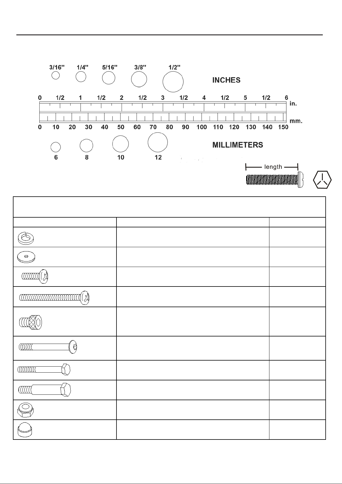
HARDWEAR IDENTIFICATION CHART
This c hart i s provided t o hel p i dentify the hardware used i n the as sem bly proc ess. P l ace t he was hers, the end of the bol ts ,
or screws on the c i rcles t o chec k for the correc t di am eter. Us e the s m al l sc al e to c heck the lengt h of the bol ts and sc rews.
NOTE: The lengt h of all bol ts and sc rews except t hose with flat heads is measured
from bel ow t he head to the end of t he bolt or s crew. Flat head bolts and
screws are measured from the t op of the head to the end of t he bol t or sc rew.
After unpac ki ng the unit , open the hardware bag and m ake s ure t hat y ou have al l the followi ng i tems. Some hardware
may be al ready at tac hed to t he part .
Pa rt No. and Description Q’TY
66 Lock Washer (M8) 4
70 Washer (8x38x2.0t) 4
80 S crew, Round Head (M5xp0.8x15mm) 18
81 S crew, Round Head (M5xp0.8x50mm) 2
83 B olt, Socket Head (M8xp1.25x10mm) 8
90 B olt, Button Head (M10xp1.5x85mm) 2
94 B olt, Hex Head (M8xp1.25x65mm) 4
95 B olt, Hex Head (M10xp1.5x50mm) 2
104 Nylon lock Nut (M10xp1.5) 2
105 Nut Cap 2
Page 4
4
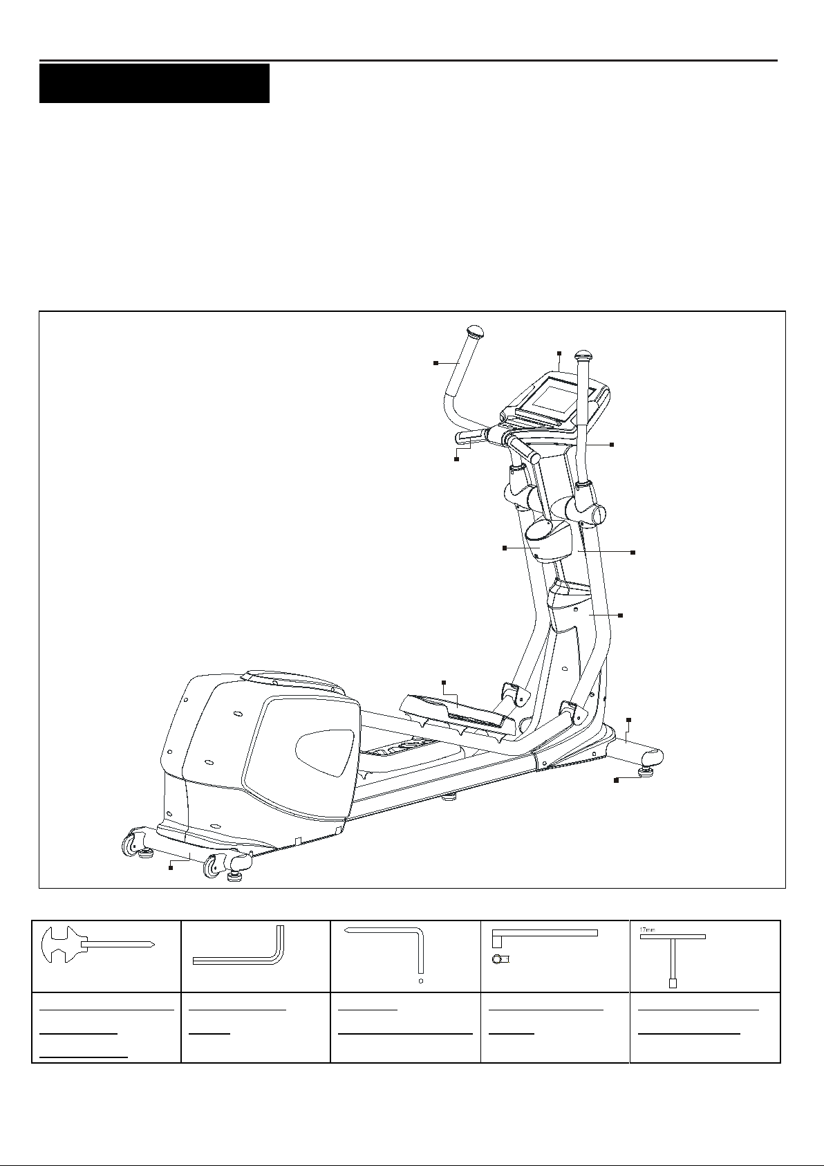
Console
Main F rame
Upright Post
“BEFORE YOU BEGIN”
Thank you for c hoosing t he CE-8.0LC Elliptical. We take
great pride in produc ing this quali ty product and hope it will
provide many hours of quali ty exercise t o m ake you feel
bett er, look bet ter and enjoy li fe to it s full est .
Yes, i t 's a proven f act that a regular exerc i se program can
improve y our phys i cal and ment al heal t h.
Foam Gri p
Too oft en, our bus y li fes ty l es li m i t our tim e and
opportunity to exercise. The equipment provides a
convenient and si m pl e m et hod to begin your as saul t on
gett ing y our body in shape and achi evi ng a happier and
healthier lifestyle.
Before reading further, please review the drawing below
and fami l i arize yours el f wi t h the part s t hat are labeled.
Read this manual carefully before using the equipment.
Handlebar
Pul s e Sens or
Plate
Acce sso r y Tra y
Rear Stabilizer
THE F O L L O WING TOOL S ARE INCLUDED FO R AS SEMBLY:
Pedal
Front St abiliz er
Leveler
MULTI W RENCH TOOL
W/ PHILLIPS
SCREWDRIVER
ALLEN WRENCH
(6 mm)
PHILLIPS
SCREWDRIVER (6mm)
SOCKET WRENCH
(13mm)
T-HANDLE SOCKET
WRENCH (17MM)
Page 5
5
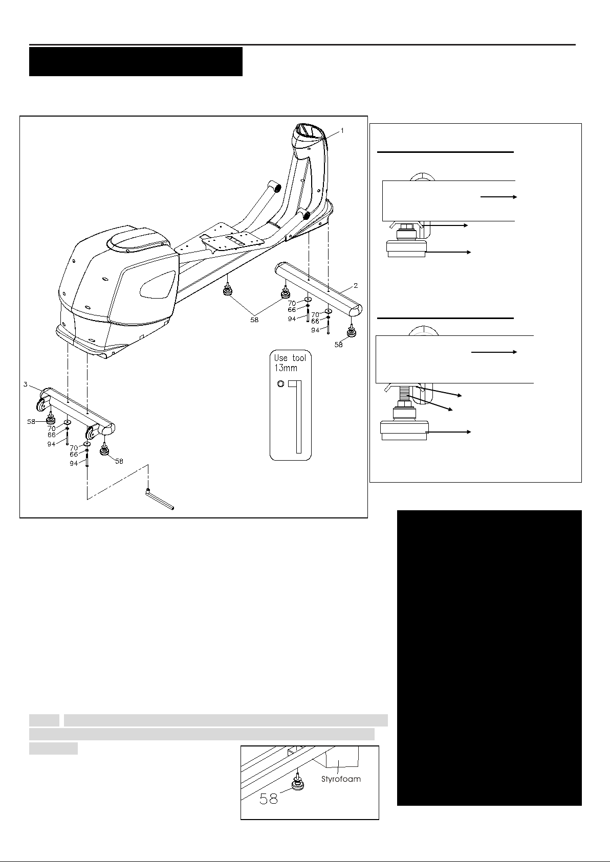
LEVELING: After placing the
2 shown.
Stabilizer
Adjustment Plate
Level er ( 5 8 )
Adjustment Plate
“ASSEMBLY INSTRUCTIONS”
Pl ac e al l parts from t he box i n a cleared area and pos i tion them on the floor in front of y ou. Remo ve all pack i ng m aterial s
from your area and plac e them back into the box. Read each s tep carefully before beginning.
STEP 1 –
a. At tac h the Leveler x 4 (58) to t he Front Stabil ize r (2) and the Rear
Stabilizer (3).
b. Be sure to t i ght en the Leveler (58) securely against the Stabilizers (2, 3)
unti l s crew c om pl etely t i ght ened as t he drawing 1 s hown on t he top right
corner.
STEP 2 – Stabilizer Assembly
At tac h the Front Stabilizer (2) and the R ear S tabili z er (3) onto t he Main
Frame (1) and sec ure wit h the 4 x Wa she rs (8x38x 2.0t) (70), the 4 x Lock
W ashe rs (M8)(66) and t he 4 x Hex Head Bolts (M8x p1.25x65mm) (94) with
the sock et wrenc h(13mm) (See pi ct ure above)
STEP 3 – Leveler Assembly
Tighten one Leveler (58) under the middle of t he Main Fram e (1) .
NOTE: It wi ll be easi er t o attac h the Leveler (58) under the Main F r am e ( 1) by
plac ing one St yrofoam (or any st ationary objec t) under one si de of t he Main
Frame (1).
Leveler Assembly
Detailed Lever- drawing 1
Detailed Lever- drawing 2
Stabilizer
Screw line
Level er ( 5 8 )
equipment in the intended
location for use, Check the
stability of the equipment. If the
equipment is not level,
reviewing the following
direction:
Loosen t he L evel er ( 5 8 ) to
make the A djustment Plate
become less tight.
A djust the Leveler (58) for
leveling.
Tighten the A djustment Plate
securely aga ins t the Stabilizer
to lock the Leveler (58) in the
stable position as the drawing
Page 6
6
“ASSEMBLY INSTRUCTIONS”
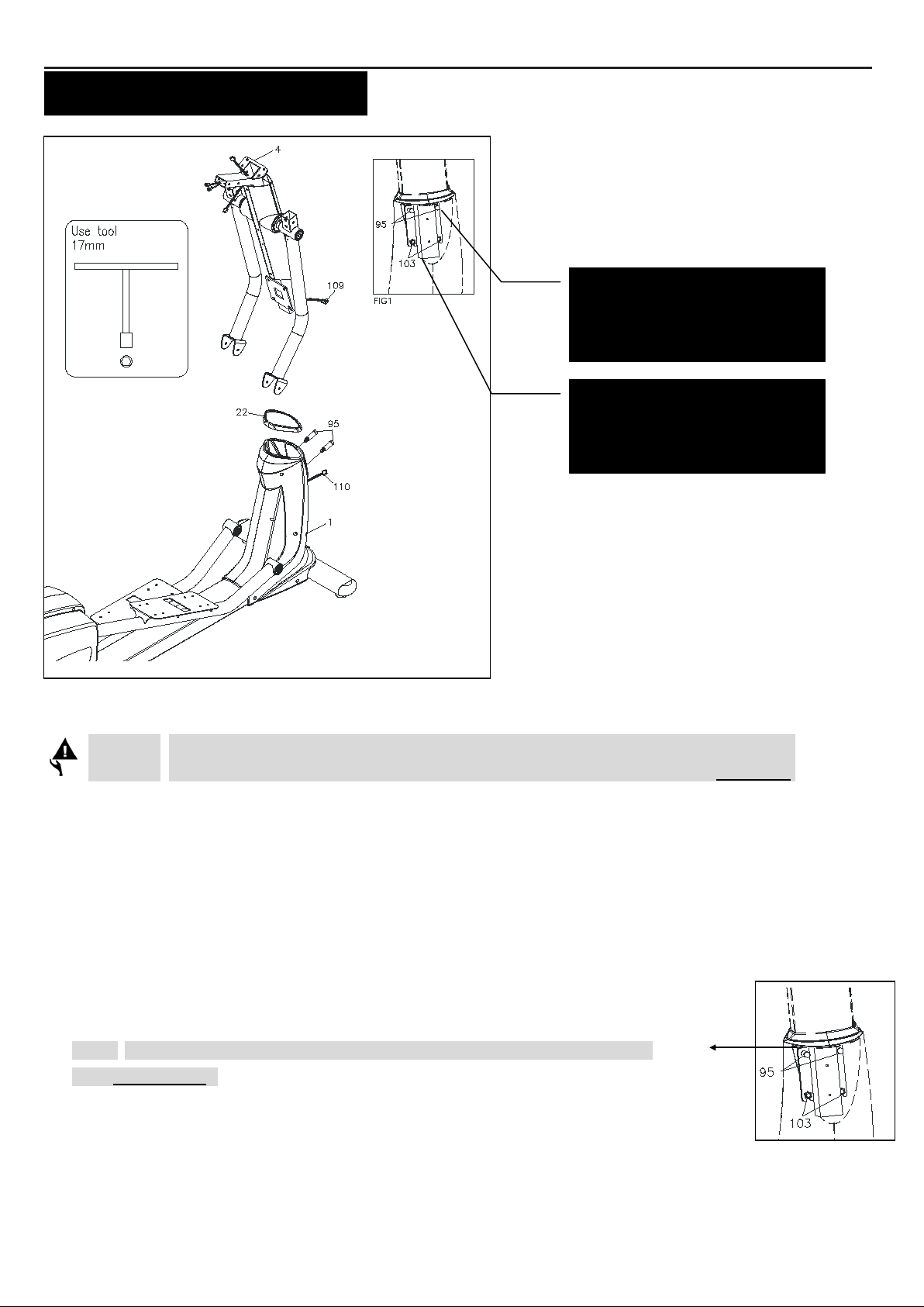
NOTE : Please do not fully
tig h ten Bo lts (95) u n til Step . 8
for the easy assembly
NOTE: Do not rem ove the l o ck
nuts (103) during a ssembl y
S
TEP 4 – U pr ight Sleeve Assembly
CAUTION: B e careful not to damage the Middle Connection Wire (109 ) while assembling Step 4 to 6.
Sl ide the Upright Sleeve (22) ont o the Upr igh t Post (4).
Refer t o t he drawi ng above. Make sure t he di rec tion of t he Upright Sleeve (22) is in the c orrec t pos i tion.
STEP 5 – Upright Post Assembly
a. Check that 2 x Nylon lock Nuts (M10x8t) (103) have preassembled i nt o the front of t he Mai n F r am e (1) as FIG1
ill ust rat i on shows on the t op right c orner, mak ing sure t hat the s l ot ted brac ket of t he upright post s l i des between the
nuts and t he frame.
b. Insert t he Upright Post (4) onto t he Mai n F r am e (1) and slightly sec ure wi t h the 2 x Hex Head
Bolts (M10xp1.5x50mm) (95) by usi ng t he T-Handle SOCKET WRENCH(17mm) as shown.
NOTE: P l e ase do not full y tighten Bolts (95) o r lock n uts (103) until Step. 7 has
been COMPLETED
STEP 6 – Wire Assembly
Pl ug t he Middle Connection Wire (109) int o the Lower Connection Wire (110 ).
Page 7
7
“ASSEMBLY INSTRUCTIONS”
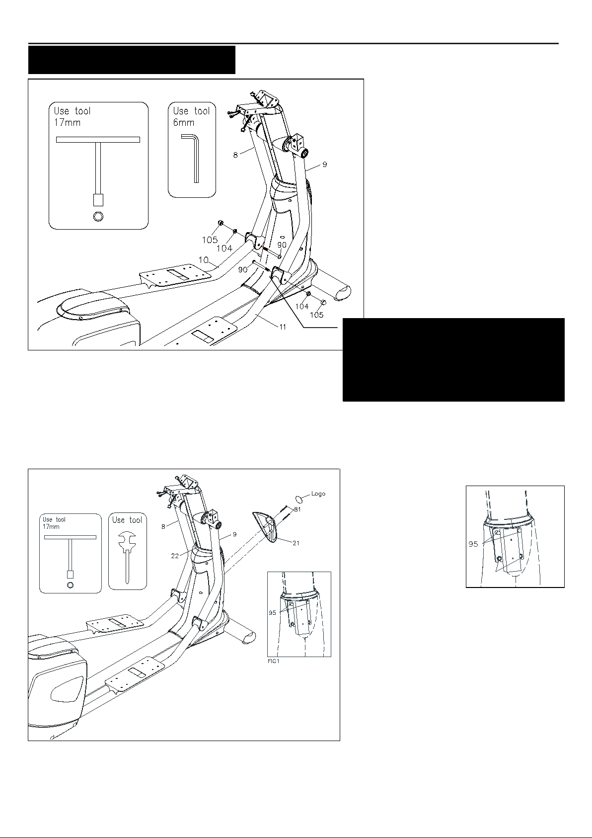
STEP 7 – Pedal S up port A rm
Note:
mak e su r e the bolts are fully tightened to avoi d noise
& Pivoti ng Arm Assembly
a. At tac h the Le ft Pedal Support Arm
(10) ont o the L eft Pi vo ting Ar m (8)
and secure wit h the 1x Button Head
Bolt (M 10xp 1.5x 85mm ) (90) and 1 x
Nylon lo ck Nu t (M 1 0x p1.5) (104).
b. Pres s t he Nu t Cap (105) onto the
Nylon lock Nu t (M10xp 1.5) (104).
c. Repeat the above procedure t o at tac h
the Right Peda l Support Arm (11)
onto t he Right P ivoting Arm (9).
NOTE: Please mak e su r e B o lts (90) are
inse rted from the i nside of the Pivoting Arm
and the Nuts (104) an d Nut Ca ps (105) are
ins talled from the outside
STEP 8 – F r o nt Decorati on Cover Assembly
a. Pl eas e go back t o full y tighten wi t h the 2 x
H ex Head Bolts
(M10xp1.5x50mm)
(95) and the 2 x
Lock nu ts (103)
with the T-Handle
SOCKET WRENCH
(17mm) as s hown.
b. At tac h the Front Decorative Upright
Cove r (21) onto t he front of t he Main
Frame (1) with t he 2 x Round He ad
Screws (M5x p0.8x50mm) (81).
c. Plac e t he Log o St i ck er on t he surf ace of the
Front De corative Upright Cover (21).
d. Sl ide the Upright Sleeve (22) down to c over the open area of t he Mai n F r am e (1) .
A logo sticker is located in one of the
hardware boxes.
Page 8
8
“ASSEMBLY INSTRUCTIONS”
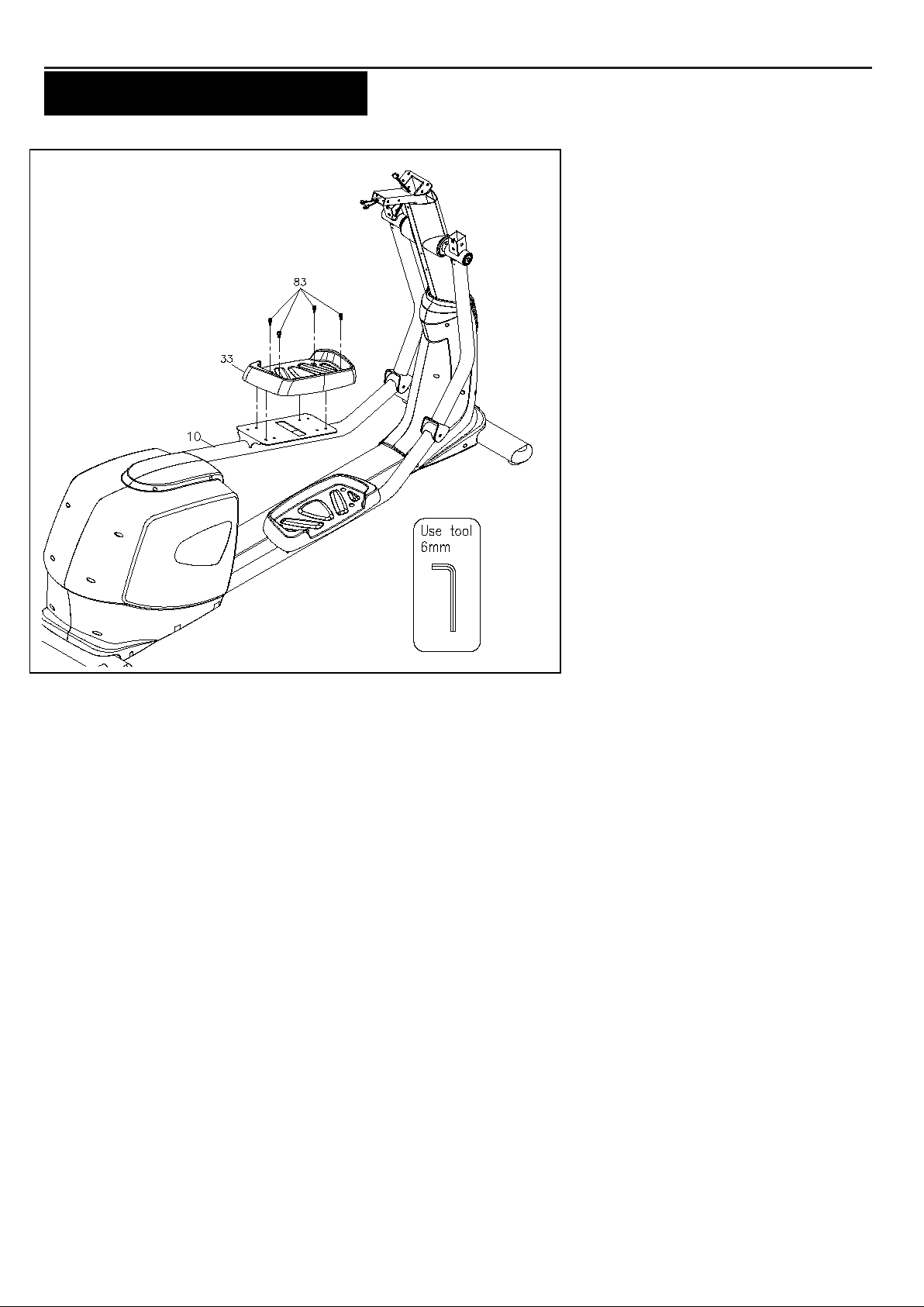
STEP 9 – Pedal Assembly
a. At tac h the Left Pedal As s embly (33L)
onto t he ped al ar m plate that is
loc ated in the m iddle of the Left Pedal
Support Arm (10) and s ecure with t he
4x Socket Head Bolt
(M8xp1.25x10mm) (83).
b. Repeat the above procedure to attach
the Right Pedal As sembly (33 R) onto
the Right Peda l Support Arm (11).
Page 9
9
“ASSEMBLY INSTRUCTIONS”
STEP 10 – C onsole B rack et
Assembly
CAUTION: B e careful not to
damage the Middle Puls e Sens or Wire
(112) while as s embling STEP 9.
Sl ide the Con so le Bra cket (18) onto the
Upright Post (4) as the FIG1 illustration
shows on t he t op right corner.
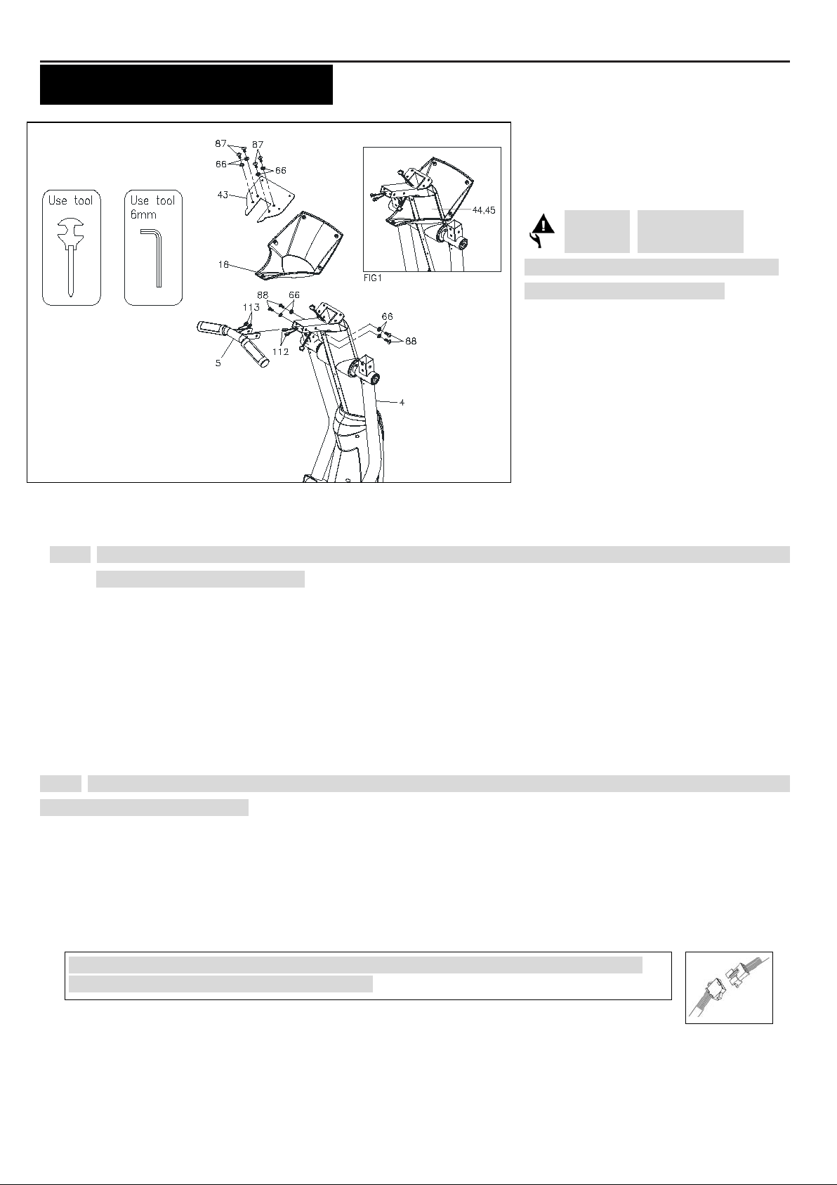
STEP 11– Console Fixed Bracket Assembly
NOTE: For s hipping purpos e, the 4 x Button Head Bolts (M8xp1.25x12mm) (87) and 4 x Lock Wa shers (M8)(66) are
att ached on t he Upright Post (4).
a. Rem ove t he 4 x Button Head Bolts (M8xp1.25x12mm)(87) and 4 x Lock Washers (M8)(66) from the Upri g h t Post
(4).
b. At tac h the Cons ole Fixed Bracket (43 ) ont o the Upright Post (4) and s ecure wi th the 4 x Button Head Bolts
(M8xp1.25x12mm)(87) and 4 x Lock Washe r s (M 8)(66)
STEP 12 – Stationary Handlebar & Wire Assembly
NOTE: For s hipping purpos e, the Button Head Bolts (M8xp1.25x16mm)(88) and L o ck Wash er s (M 8)(66) are att ached
on the Stationary Handlebar (5).
a. Remove the 4 x Button Head Bolts (M8xp1.25x16mm)(88) and 4 x Lock W a she rs (M8)(66) from the Stationary
Handlebar (5) .
b. Connect the Middle Pulse Sensor Wire (11 2) and t he Lower Puls e Sens or Wire (113 ) to t he Stationary
Handlebar (5) .
NOTE: A fter connec ting t he wires’ pins, sli ght ly and gentl y pull t wo si des of wires to test and
mak e sure whet her t he wires are fully c onnect ed.
c. Ins ert the Stationary Handlebar (5) int o the Upr igh t Post (4) and sec ure with t he 4 x Button
Head Bolts (M8xp1.25x16mm)(88) and 4 x Lock W a she r s ( M 8 )(66).
Page 10
10
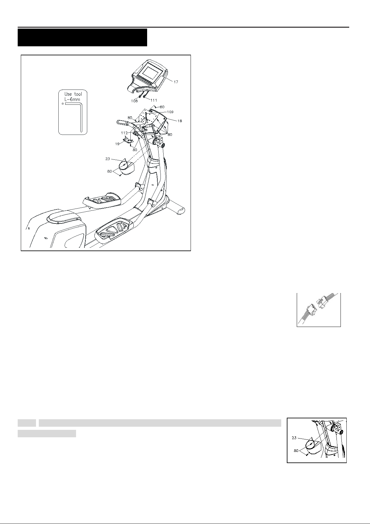
“ASSEMBLY INSTRUCTIONS”
STEP 13 – Wire Assembly
a. Connect the Upper Pulse Sensor Wire (111) to the Middle Puls e Sens or Wire (112 ) .
b. Connect the Upper Connection Wire (10 8) to the Middle Connection Wire (109 ).
NOTE: The num ber of wire pin shoul d be t he sam e for both wi res to connec t wit h as t he drawing
shown on t he right .
STEP 14 – C onsole & Consol e Br ack et Assembly
a. Pl ac e the Consol e (17) o nto t he Upri g h t P ost (4) an d s ecure with t he Roun d He ad Screws (M5x p0.8x 15m m) (80 ).
b. At tac h the Console Ba ck Cove r (19) to the Consol e (17) under the Stationary Handlebar (5) and s ecure wit h the
Round He ad Screws (M5x p0. 8x15m m) (80).
c. S l i de the Console Bra cke t (18) ont o the Console (17) and sec ure with t he Round Head Screws (M5xp0.8x15mm)
(80).
STEP 15 – A ccessory Tr ay Assembly
NOTE: For s hipping purpos e, the Round Head Screws (M5xp0.8x 15mm ) (80) are at t ached on
the Upri ght P ost (4).
a. Remove the Round Head Screw (M8xp1.25x 15mm) (80) from t he Upr igh t Post (4).
b. At tac h the Acce ssory Tray (23) onto t he Upright Post (4) and secure wit h the Round
Head Screw (M5xp0.8x 15mm) (80).
Page 11
11
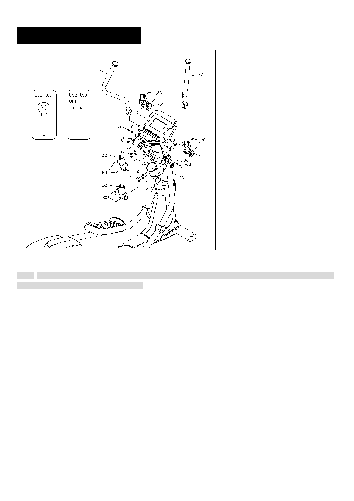
“ASSEMBLY INSTRUCTIONS”
STEP 16 – U pper Handlebar Assembly
NOTE: For s hipping purpos e, the Button Head Bolts (M8xp1.25x16mm)(88) and Lock W a she rs (M 8)(66) are at tac hed
on the Left and Right Action Handlebar (6, 7).
a. Remove the 8x Button Head Bolts (M8xp1.25x16mm) (88) and 8 x Lock W ashe rs (M8) (66) from the Le ft and
Right Action Handlebar (6, 7).
b. Foll owing the assembly drawi ng, i nsert the Right Action Ha ndl eba r (7) onto the Right Pivoting Arm (9) and secur e
with the 4x Button Head Bolts (M8xp1.25x16mm)(88) and 4 x Lock W ashe rs (M 8 ) (66).
c. Repeat the above procedure t o i nsert and secure the Left Action Handlebar (6) onto t he Left Pi v o ti n g Ar m (8).
STEP 17 – A ction Arm Cover Assembly
a. Pl ac e the Front Ac tion Arm Cove r (31) and t he Back Acti on Ar m Co ver (32) over the Right P ivoting Arm (9).
b. Fasten the Covers t ogether wit h the 4 x Round Head Screws (M 5xp 0.8x 15mm ) (80).
c. Repeat the above procedure t o pl ace t he Front Acti on Arm Co ve r (31) and the Back Acti o n Ar m Co ver (32) at
both sides of the L eft Pi v o ti n g Ar m (8).
For the final st ep, mak e sure all t he bol ts and nuts are tighten s ecurely before usi ng.
Page 12
12
A
B
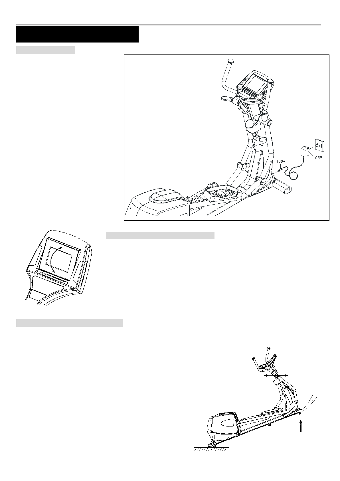
“OPERAT ION INSTRUCTIONS”
A. POWER SUPPLY
The power connec ts to t he front of
the Mai n F r am e (1.)
Pl ug t he adaptor’s Power Cord
(106B) into an 110v electrical
outlet.
B. CONSOLE ANGLE ADJUS TMENT
To get the bes t vie wable angle, pres s t he area A or B t o adjust t he di s pl ay up or down.
C. HOW TO MOVE THE ELLIPTICA L
Move this el l i pt i cal by l ift i ng from the front stabilizer and rol l the ell i ptical on the wheels locat ed on the rear s tabil i zer.
This ell i pt i cal m ay reqire t wo peopl e to move.
Make sure the floor is level while moving the elliptical.
Page 13
13
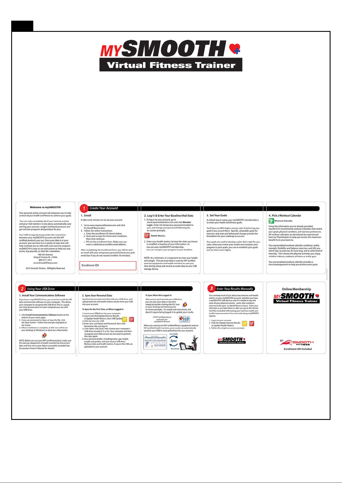
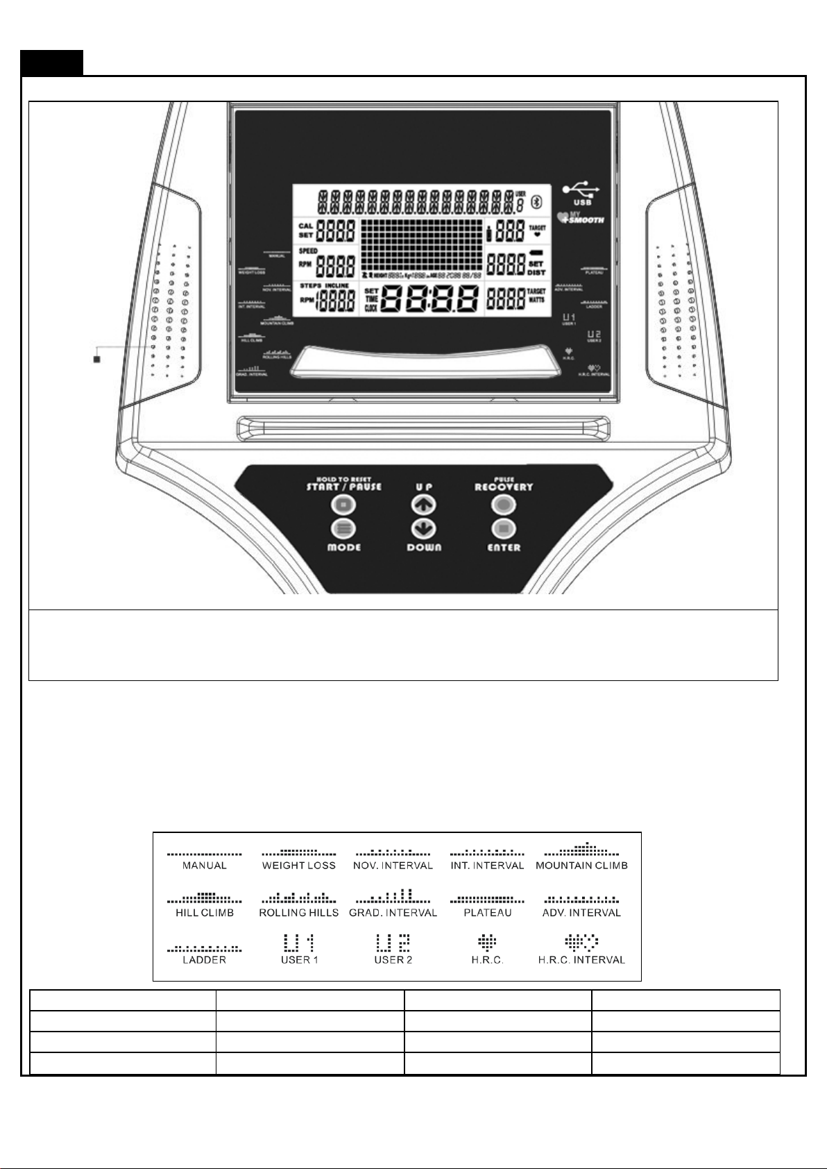
COMPUTER OPERATION
Whether yo u
in a healthy lifestyle , the MY SMOOTH
make positive steps to a healthier lifest yle. These five steps combined wit h the too ls b uilt
*Not all Smooth Fitness products include the Smooth Customer Care Kit
Congratula tions t his product i s eq uipped with the M Y S MOOTH Vi rtual Fitness Trainer.
want to lose weight, train for a sporting event, or simply mainta
Virtual Fitnes s Trainer prov ides th e tools, stru cture and support you need to be fit an d liv e healthy. The
5 simple steps, o utlined in t he c usto mer c are ki t* a re proven to help you lose weight, improve your
he a lth, a nd
into your online account, will provi de you wi th a great start toward achieving your goals.
To s et u p your account, ref er to th e instructions in the Gettin g Started Guide cont ained in your Smoot h
Fitness customer care kit or vi sit www.my smoothtrainer.com
Page 14
14
COMPUTER OPERATION
T
keep you on t rack
MANUAL
P1 WEIGHT LOSS
P2 NOV. INTERVA L
P3 INT. INTERVAL
P4 MOUNTAIN CLIMB
P5 HILL CLIMB
P6 ROLLING HILLS
P7 G RAD. INTE RVAL
P8 PLATEAU
P9 ADV. INTERVA L
P10 LADDER
P11 USE R 1
P12 USE R 2
P13 H.R.C.
P14 H.R. C. INTERVA L
Speaker
We rec om mend t hat you use t he c onsol e to help vary your workout rout i ne and keep y ou foc used on y our proces s
ake a few m i nut es t o review the c onsole l ayout . B el ow is an overview of t he console’s feat ures and functions
toward your fitnes s goals . The c onsole c an bec ome an import ant s ource of mot ivati on and i nteres t whic h will help
Power ON
a. Mak e sure t he item’s adapt or i s c orrec tly pl ugged i nt o the s ocket
b. Pedal ing or pressi ng any k eys to act i ve t he console. The c onsole di splay wil l t hen l i ght up wit h a short beep sound,
indic ati ng the consol e will be ready for use
Power Off
The cons ol e woul d aut om atical l y shut off after 5 m i nutes of inact i vity
Program List
Page 15

15
COMPUTER OPERATION
C
console wi l l ret urn t o POWE R ON s tat us.
to POW ER ON status.
onsole Buttons
a. Press START /PAUSE to begin your ex ercis e
b. Press
c. Press
d. HOLD T O RES ET function: Pres s and hol d START /PAUSE, all the data will return t o 0 and t he
Press ENTER to confirm the program function (P ROGRAM, TIME, HEIGHT, W EIGHT, AGE, TARGET
H.R. and LEVEL in each time interval).
Press UP to i ncreas e t he values of t he program function (PROGRAM, TIME, HEIGHT, W EIGHT, AGE,
TARGET H.R. and LEVEL i n ea ch t i me i n terv al ).
Press DOWN to decrease t he val ues of the program funct ion (PROGRAM, TIME, HEIGHT, WEIGHT,
AGE, TARGET H. R. and LEVE L in each time interval).
START /PAUSE again to st op and pause al l funct ions during your ex erc i se program. A l l t he
data on the display wil l then pause.
START /PAUSE agai n to res um e the pr ogram and al l the dat a di splayed wil l cont i nue until t he
program has finis hed.
**The button is only
suitabl e to use whe n the
USB is pl ugged into the
console**
Press MODE to rev iew Calendar Mode.
Hold MODE for a few sec onds, to go into Calendar
Mode to edi t year/ m onth/ dat e/hour/ m i nut e.
Press Start/ Pause /Hold to reset to return
a. PULSE RECOVERY butt on m easures how qui ck l y y ou ret urn
to a res ting heart rat e after exerc is ing. You c oul d us e this
butt on to m eas ure i m provement as you get i nto s hape.
b. The c onsole will m onitor y our puls e for 60 seconds and
cal culate a HEART RATE RECOVERY value from F1. 0 to
F6.0. F1.0 i s the Highest ; F6.0 is the Lowest (For Reference
Only).
c. The readout s houl d onl y be us ed as a compari son bet ween
workout s. It’s recomm ended t o use right after any aerobi c
exercise. Stop exerc i sing before st arting this function.
NOTE:
If y ou don’t hold t he HEART RATE SENSORS on the handrail s wit h both hands properly, t he console’s
HEART RATE value will show “0” and t he main sc reen would show “F6.0” after t he cons ol e c ount s down
to zero, If the sens or was unable to read your heart rate. Press st op then pres s t he P ULS E RECOVERY
butt on again. Repl ace y our hands on t he pul se s ensors .
d. Your pulse wil l be di splayed in approximately 5 sec onds after
the heart sy mbol “
” is displayed.
Calendar Mode
Page 16

16
COMPUTER OPERATION
C
onsole Buttons
Speaker Sound Sys t em:
a. To use the music feature, s i m pl y c onnect any MP3/ CD player t o the LINE
IN jack on the console.
b. Lis ten t o t he m usi c , eit her through headphones or speakers .
c. Us e the “Volume Knob”
To record y our exerci se and health metrics, y ou m ust l og on
to www.mysmoothtrainer.com
Trainer USB devic e. Once c omplete sim pl y plug i n the MY Smooth Virtual
Fitness Trainer US B device to y ou compatibl e Smooth Fi tness exercise
mac hine. Di splay ed on the equipment wil l be your name, weight height and
age. Press “S TART” butt on to begin your workout, t he cons ol e wi l l rec ord your
exercise dat a automaticall y, every 20 s econds , t o your MY Smooth Virtual
Fitness Trainer US B device. After your exercise session is complete, Insert
the M Y Smooth device in to the USB port of your P C or MAC to upload your
data to The M Y Smoot h Vi rt ual F itnes s Trainer onl ine health m anagement
program. The detailed reports s how your ex ercis e and healt h result s, trends
and rec om m endations to bett er achieve and maint ain y our fitnes s goals.
t o adj ust t he s ound level.
. Then sync your MY Smooth Virtual Fitness
Page 17

17
COMPUTER OPERATION
C
Display range: 0 ~ 9999.
down to 0:00.
: Display POWER SUPPLY status.
console.
onsole Functions
CALORIES:
Count Up: M easuring tot al calori es y our body burned during
exercise.
SPEED:
Displ ays t he current speed KM/MILE during exercise.
RPM (Rotation Per Minute):
Displ ay range: 0 ~ 999.
TIME:
Count Up: If a t arget tim e was not select ed, TIME wil l count
up from 0:00 t o max imum 99:59 minutes.
Count Down: If you have set the t arget t i m e (0: 00 ~ 99: 00),
the cons ol e wil l c ount down from that sel ect ed target t ime
WATTS:
Displays t he c urrent val ue of W att during exerc is e.
Displ ay range: 0 ~ 9999.
DISTANCE:
Count Up: If a t arget distance was not select ed, this would
meas ure the t ot al di st ance from 0: 00 to 999.9 k m/ mile.
Count Down: If you have set the t arget dist ance, the
console wi l l count down from t hat sel ect ed t arget dist ance
down to 0.
HAND PULSE / HEART RATE:
To dis play your heart rate you must wear the chest bel t or
plac e both of y our hands on the Pulse Sensors located on
the Handlebars. Your puls e wi l l be displ ayed approx i matel y
5 sec onds after the heart sy mbol “
If you do not wear the c hest bel t or place y our hands
correctly on the pul se sens ors, t he com put er wi ll shut off the
puls e circ uit . To react i vate the pulse feature, properly place
your hands bac k on t he P ul se S ensors and the pulse
readout will appear again.
” is displayed.
: When the MY SMOO T H USB is plugged i nto t he
console, the USB signal will be di splayed on the
Page 18

18
COMPUTER OPERATION
GENDER:
Displ ay range:
Male:
Female:
AGE:
Displ ay range:
HEIGHT:
Displ ay range:
3 FEET 4 INCHES ~ 7 FE ET; 1 INCH i ncrements / 101 ~ 214
CM; 1 CM i ncrements; the product is not recomm ende d for
use by children.
WEIGHT:
Displ ay range:
45 ~ 400LBS ; 1 LB increments / 20 ~ 181 KGS; 1 K G
increments; the product is not re comm ende d for use by
children.
10 ~ 99 years old; in 1 year increments
NOTE: Although the cons ole allows input for age
begi nni ng at 10 years old, the product is not
recommended for use by children.
TARGET H.R.:
Displ ay range:
50 ~ 180 BP M (beat s per mi nute) ; 1 B PM i ncrements.
Page 19

19
COMPUTER OPERATION
QUICK START :
ENTER the USER DATA
or
“1” Press any but t on on t he console t o t ur n on the console
a. Make s ure that the power cord i s properly plugged into t he soc ket .
b. The console woul d aut om atical l y shut off after 5 mi nutes of inact i vity.
c. P ress any but ton on t he cons ole to turn on t he c onsol e. After a fe w s econds, t he cons ole will then li ght up wit h a short
beep sound, indic ati ng the consol e will be ready for use.
“2””Start Pause” button, as an easy way to reset the comput er and ent er int o POWER O N st at us
Hold the START/PAUSE button for a few s ec onds to reset t he com put er and ret urning
all work out values to z ero, and ent er into POW ER ON status.
P OW ER O N sta tus
3” MANUAL PROGRAM
“A.“ENTER MANUAL PROGRAM”
Pressing When i n P ower on st atus
press t he st art butt on t o i m m edi ately
st art a m anual program
Pres s t he UP or Down B ut ton unt i l M A NUA L i s
dis pl ayed. P ress Ent er t o confirm. Onc e the
MA NUAL program has been chos en you wil l
enter y our personal informat ion by following
the di rec tions on t he next page.
Page 20

20
COMPUTER OPERATION
a. After pres si ng
“B. SET YO UR GEND ER “
UP or Down button t o ent er into MANUAL PROGRAM press ENTER to Confirm, the GENDER
function mode will appear with
b. Use UP or DOWN buttons t o set your gender (Male: or Female: ).
c. Press the ENTER button to confirm.
/M ale ic on dis pl ay flas hi ng.
“C. S ET YOUR AG E“
a. The AGE function will appear with the AGE di splay flashing.
b. Use the
INCREMENTS).
c. Press the ENTER button to confirm .NOTE: Although the console all ows input for age
begi nni ng at 10 years old, the product is not recom m e nded for use by children
UP or DOWN buttons to set your AGE (10 ~ 99 YEARS OLD; in 1 YEAR
“D. S ET YOUR HEI G HT “
a. The HEIGHT function wi l l appear with the HEIGHT displ ay flas hing.
b. Use the
FEET; 1 I NC H INCREMENTS/ 101 ~ 214 CM; 1 CM INCREMENTS).
c. Press the
NOTE for HEIGHT: The product i s not recomm e nded for use by chil dren
NOTE for WEIG HT: The product is not recomm ende d for use by chil dre n
ENTER button to confirm.
“E. S ET YO U R WEIG H T“
a. The WEIGHT function wi ll appear wit h the WEIGHT dis play flashing.
b. Use the
LBS /KG I NCREMENTS).
c. Press the
UP or DOWN buttons to set your WEIGHT (45 T O 400 L BS / 20 TO 181KGS; 1
ENTER button to confirm.
UP or DOWN buttons to set your HEIGHT (3 F EET 4 IN C HES ~ 7
Page 21

21
COMPUTER OPERATION
“F. SET THE TIME“
a. The TIME function will appear with the TIME dis play flashing.
b. Use the
INCREMENTS).
NOTE for TIME:
Count Up: If a t arget tim e was not select ed, the TIME wil l count up from 0:00 t o a maximum of 99:59 minutes
Count Down: If y ou have s et t he target tim e, t he cons ol e wi l l c ount down from t hat sel ec ted t arget t ime t o
0:00
c. Press the
UP or DOWN buttons to set the desired TIME (00:00 TO 99:00; 1 MINUTE
ENTER button to confirm.
“G. START TO EXERCISE”
START / PAUSE to begi n your exercise.
Press
“H. CHANG ING THE RESIS TANCE S ETTI NG”
You can c hange t he resistance level (from 1 to 16 levels) at any t i m e duri ng work out
by press i ng the
UP or DOWN button
Page 22

22
COMPUTER OPERATION
“C
ONSOLE INSTRUCTIONS – PROGRAM (P2 ~ P10)”
“A.“ENT ER THE PRES ET PROGRAM S”
To enter one of the nine preset programs.
a. Press any button on the console to turn on the console. After a few sec onds, the c onsole wi l l t hen l i ght up wit h a
short beep sound, i ndi cat i ng the c onsole wi l l be ready for us e.
Mak e sure t hat the power c ord i s properly plugged i nto t he soc ket .
b.
c. The cons ol e woul d automaticall y s hut off aft er 5 m i nut es of i nactivity.
d. P ress the UP or DOWN but tons to s el ect program 2 ~ 10 (SE E P ROGRA M S ELE CTION ON PAGE 25)
e. Onc e the preferred program is dis play ed press enter t o c onfirm.
f. Ent er your USER Data
“B. SET YO UR GEND ER “
a. After pres si ng
UP or Down button t o ent er i nto MANUAL PROGRAM press ENTER to Confirm, t he GENDER
function mode will appear with /M ale ic on dis pl ay flas hi ng.
b. Use UP or DOWN buttons t o set your gender (Male: or Female: ).
c. Press the ENTER button to confirm.
“C. S ET YOUR AG E“
a. The AGE function will appear with the AGE di splay flashing.
b. Use the
c. Press the ENTER button to confirm .NOTE: Although the console all ows i nput for age beginning at 10 years old, the
product is not recomm ende d for use by childre n.
UP or DOWN buttons to set your AGE (10 ~ 99 YEARS OLD; in 1 YEAR INCREMENTS).
Page 23

23
COMPUTER OPERATION
“D. S ET YOUR HEI G HT “
a. The HEIGHT function wi l l appear with the HEIGHT displ ay flas hing.
b. Use the
FEET; 1 I NC H INCREMENTS/ 101 ~ 214 CM; 1 CM INCREMENTS).
NOTE for HEIG HT: The product i s not recomm ende d for use by chil dre n
“E. S ET YO U R WEIG H T“
a. The WEIGHT function wi ll appear wit h the WEIGHT dis play flashing.
b. Use the
LBS /KG I NCREMENTS).
c. Press the
NOTE for WEIG HT: The product is not recomm ende d for use by chil dre n
c. Press the
UP or DOWN buttons to set your WEIGHT (45 T O 400 LBS / 20 TO 181KGS; 1
ENTER button to confirm.
UP or DOWN buttons to set your HEIGHT (3 F EET 4 IN C HES ~ 7
ENTER button to confirm.
“F. SET THE TIME“
a. The TIME function will appear with the TIME dis play flashing.
b. Use the
INCREMENTS).
c. Press the
NOTE for TIME:
Count Up: If a t arget tim e was not select ed, the TIME wil l count up from 0:00 t o a maximum of 99:59 minutes
Count Down: If you have s et the t arget tim e, t he cons ol e wi ll count down from that select ed target tim e to
0:00
UP or DOWN buttons to set the des i red TIME (00:00 TO 99:00; 1 MINUTE
ENTER button to confirm.
Page 24

24
COMPUTER OPERATION
“G. START TO EXERCISE”
START / PAUSE to begi n your exercise.
Press
“H. CHANG ING THE RESISTANCE SETTING”
You can c hange the resistance level (from 1 to 16 levels) at any t i m e duri ng work out by press i ng the UP or DOWN button
Page 25

25
COMPUTER OPERATION
P1 WEIGHT LOSS P2 N OVICE I NTERV AL
P3 INTERMEDIATE INTERVAL P4 MOUNTAIN CLIMB
P5 HIL L C LIMB P6 RO LLING HILLS
P7 GRADUATING INTERVAL P8 PLATEAU
P9 ADVAN CED I N TER V AL P10 LADDER
Page 26

26
COMPUTER OPERATION
“CONSOLE INSTRUCTIONS – PROGRAM (P11 ~ 12)”
P11 USER 1 P12 U S ER 2
“1” To enter one of the 2 USER programs .
a. Press any button on the console to turn on the console. After a few s econds , the c onsol e wil l then li ght up wit h a
short beep sound, i ndi cat i ng the c onsole wi l l be ready for us e.
b. Make sure that the power c ord is properly plugged into t he soc ket .
c. The c onsole woul d aut om atical l y shut off after 5 mi nutes of inact i vity.
d. Press t he UP or DOWN but t ons t o select program 11~12
e. Once t he preferred program is dis played pres s ent er to confirm.
f. Ent er your USER Data
“B. SET YOU R GENDER “
a. After press i ng
UP or Down button to ent er into MA NUAL PROGRAM press ENTER to Confirm, the GENDER
funct i on m ode wil l appear with
b. Use UP or DOWN buttons t o set your gender (Male: or Female: ).
c. Press the ENTER button to confirm.
/M ale ic on dis pl ay flas hi ng.
Page 27

27
COMPUTER OPERATION
”C. SET YOUR AGE”
a. The AGE function will appear with the AGE display flashing.
b. Use the
c. Press the ENTER button to confirm .NOTE: Although the console a l l ows input for age beginning at 10 years ol d, the
product is not recomm ende d for u se b y chi ldren
“D. S ET YOUR HEI G HT “
“E. S ET YO U R WEIG H T“
UP or DOWN buttons to set your AGE (10 ~ 99 YEARS OLD; in 1 YEAR INCREMENTS).
a. The HEIGHT function wi l l appear with the HEIGHT displ ay flas hing.
b. Use the
FEET; 1 I NC H INCREMENTS/ 101 ~ 214 CM; 1 CM INCREMENTS).
c. Press the
NOTE for HEIG HT: The product i s not recomm ende d for use by chil dre n
a. The WEIGHT function wi ll appear wit h the WEIGHT dis play flashing.
b. Use the
LBS/KG INCREMENTS).
c. Press the
NOTE for WEIG HT: The product is not recomm ende d for use by chil dre n
UP or DOWN buttons to set your WEIGHT (45 TO 400 LBS / 20 TO 181KGS; 1
ENTER button to confirm.
UP or DOWN buttons to set your HEIGHT (3 F EET 4 IN C HES ~ 7
ENTER button to confirm.
Page 28

28
COMPUTER OPERATION
“F. SET THE TIME“
a. The TIME function will appear with the TIME dis play flashing.
NOTE for TIME:
Count Up: If a t arget tim e was not select ed, the TIME wil l count up from 0:00 t o a maximum of 99:59 minutes
Count Down: If y ou have s et the t arget tim e, t he cons ol e wi ll count down from that select ed t arget t i m e t o
0:00
”G. START TO EXERCISE”
b. Use the
INCREMENTS).
c. Press the
Press
UP or DOWN buttons t o set the des i red TIME (00:00 TO 99:00; 1 MINUTE
ENTER button to confirm.
START / PAUSE to begi n your exercise.
“H. CHANG ING THE RESIS TANCE S ETTI NG”
You can c hange the resistance level (from 1 to 16 levels) at any t i m e duri ng
workout by pres sing the
UP or DOWN button
“2” Programming the 2 USER programs.
a. Once t he US E R dat a has been ent ered press the UP or DOWN butt ons t o adj ust t he l evel of t he first segment.
b. Press ent er t o confirm and m ove t o the nex t s egment
c. Repeat t hi s process unt i l the preferred program has been c omplet ed.
d. Press s tart to save and begin t he program
e. This program can be overwrit ten at any t i m e i n t he set up screen.
Page 29

29
COMPUTER OPERATION
“1” Prior information: Press any but t on on t he console to turn on t he console
a. Make sure t hat t he power cord i s properly pl ugged i nt o the s ock et.
b. The cons ol e woul d automaticall y s hut off aft er 5 mi nutes of inact i vity.
c. Pres s any butt on on the c onsole to t urn on t he console. After a few seconds, t he cons ol e wi l l t hen l i ght up wit h a short
beep sound, indic ati ng the consol e will be ready for use.
“2” Prior information: ”HOLD TO RESET” button, an easy way to reset and enter into POWER O N
status
Continue pressing
button a few sec onds, al l t he date wil l
reset to t he i ni tial value and the c onsole
will ret urn to POW ER ON status.
HOLD TO RESET
PO WER ON sta tus
“3” P ROGR AM (P 13 )
“A. ENTER P13“
UP or DOWN button and t hen ENTER button:
Press UP or DOWN button to s el ect P ROGRAM (P13) and then press ENTER butt on to confirm and ent er
PR OGR AM (P 1 3 ).
“B. SET YO UR GEND ER “
UP or DOWN button & t hen ENTER button:
a. After pres si ng the
ENTER button to enter into H .R .C. PROGRAM (P13), t he GENDER funct ion mode wil l appear
with
b. Use UP or DOWN buttons t o set your gender (Male: or Female: ).
c. Press the ENTER button to confirm your GENDER and enter t he m ode to s et the AGE.
/Mal e icon display flas hi ng.
Page 30

30
COMPUTER OPERATION
“C
H.R.C. P
ONSOLE INSTRUCTIONS –
“C. SET YOUR AGE“
ROGRAM (P13)”
UP or DOWN button & t hen ENTER button:
a. The AGE funct i on m ode wi l l appear with t he value of AGE display flas hi ng.
b. Use
c. Press the ENTER button to confirm AGE value and ent er the HEIGHT
UP or DOWN buttons to s et y our personal AGE (10 ~ 99 YEARS OL D; 1
YEAR-OLD INCREMENT).
mode. NOTE: Although the cons ole allows input for age beginning at 10
yea rs ol d, the product is not recomm ende d for children’s use
“D. S ET YOUR PERSO NAL HEIG HT “
UP or DOWN button & t hen ENTER button:
a. The HEIGHT function mode wi ll appear wi t h the value of HEIGHT
dis pl ay flas hi ng.
b. Use
c. Press the
NOTE for HEIG HT: The product is not recomme nded for childre n’s use
“E. S ET YOUR P ERS O NAL WEIGHT “
ENTER button to confirm HEIGHT value and enter the WEIGHT mode.
UP or DOWN buttons to s et y our personal HEIGHT (3 FEET 4
INCHES ~ 7 F EET; 1 INCH incre me nt / 101 ~ 214 CM; 1 CM
INCREMENT).
UP or DOWN button & t hen ENTER button:
a. The WEIGHT function m ode wi l l appear wit h the value of WEIGHT display flas hi ng.
b. Use
c. Press the
NOTE for WEIG HT: The product is not recomme nded for childre n’s use
UP or DOWN buttons to set y our pers onal WEIGHT (45 TO 400 LBS / 20 TO
181KGS; 1 LBS/KG INCREMENT).
ENTER button to confirm WEIGHT value and enter t he TIME mode.
“F. S ET THE D ESIR ED T IME“
UP or DOWN button & t hen ENTER button:
a. The TIME functi on m ode wi l l appear with t he value of TIME dis pl ay flas hi ng.
b. Use
c. Press the
UP or DOWN buttons to s et t he desired TIME (00:00 T O 99:00; 1 MI NUTE
INCREMENT).
ENTER button to confirm TIME value and ent er the TARGET HEART
RATE mode.
Page 31

31
COMPUTER OPERATION
“C
H.R.C. P
ONSOLE INSTRUCTIONS –
“G. SET THE TARGET HEART RATE
ROGRAM (P13)”
UP or DOWN button & t hen ENTER button:
a. The TARGET HEART RATE funct ion mode wil l appear with the value of TARGET
“H. S TART EXERCIS E”
HEART RATE display flas hi ng.
b. Use
(BEATS PER MINUTE; 1 BPM INCREMENT).
c. Press the
UP or DOWN button to set your desired TARGET HEART RATE (50 ~ 180 BPM
ENTER button to confirm TARGET HEART RATE value.
START / PAUSE button: Press START / PAUSE t o begi n exercise.
I. MUST-KNOWN HEART RATE PROGRAM INFO.”
CONSOLE MONITOR YOUR CURRENT PULSE TO CO M PARE W ITH
SETTING TARGET HEART RATE:
3 minute WARM UP time: After ent er t he H.R.C. program , t he program wil l st art
begin wit h 3 minut e W ARM UP ti me, during t he WA RM UP mode, t he c onsole wil l
detect s t he user’s heart rat e through hand puls e sens ors or wirel ess ches t belt.
Duri ng the WARM UP tim e,
~ 16 levels.
A fter the 3-minute warm up i s c om pl ete, t hen go i nto t he H. R. C. mai n program (the tim e wil l change t o your des i red
step-up tim e, t he res i st ance wil l ret urn t o the Level 1). The c onsole at this t i m e will m oni tor your ac tual pul se and
adjus t t he res i st ance/ torque l evel automat i call y t o keep your pulse wit hin your TARGET HEART RATE ZONE.
If y ou current pul se > (t he value of the TARGET HEART RATE + 10), the consol e would decrease one
resistance/torque level automatically.
If y ou current pulse < (the value of t he TARGET HEART RATE - 10), the c onsole woul d increase one
resistance/torque level automatically.
NOTE: During H.R.C. main program, if you do not wear a
ches t belt or place your hands correctly on the puls e
s ens ors, after 30 s econds, the console will dis play “NO
HEART RATE” message and then turn off the pulse circuit
and st op the program. The console will then display an
error message “PAUSE”. Press START button and be s ur e
to we ar a chest be l t or pla ce your hands back on the Pulse
Sens ors correctly, t he pulse readout will appear again and
continue s tarting the program.
YOUR
t he t orque/res i st ance level is available to adjust from 1
Page 32

32
COMPUTER OPERATION
“C
H.R.C. I
any button on the console or begi n pe daling t o turn on t he console
ONSOLE INSTRUCTIONS –
NTERVAL PROGRAM (P14)”
“1” Prior inf or m at ion: Press
a. Make sure t hat t he power cord i s properly plugged into the socket.
b. The cons ol e woul d automaticall y s hut off aft er 5 mi nutes of inact i vity.
c. Pres s any butt on on the c onsole or begi n pedaling to turn on the c onsole. After a few seconds, t he console wil l then
light up wit h a short beep sound, indic ating t he c onsole wil l be ready for use.
“2” Prior information: ”HOLD TO RESET” button, an easy way to reset and enter into POWER
ON status
Continue pressing
button a few sec onds, al l t he date wil l
reset to t he i ni tial value and the c onsole
will ret urn to POW ER ON status.
HOLD TO RESET
“3” N ormal way to operate P ROGRAM (P14)
“A. ENTER P14
UP or DOWN button and t hen ENTER button:
Press UP or DOWN button to s el ect H.R. C. INTERVAL P R OGRAM (P1 4 ) and then press ENTER button to
confirm and enter
“B. SET YOUR G ENDER
PR OGR AM (P 1 4 ).
UP or DOWN
a. After pres si ng the
button & then ENTER button:
ENTER button to enter into H.R.C. INTERVAL
PO WER ON sta tus
PROGRAM (P14)
b. Use UP or DOWN buttons to s et y our gender (Male: or Female: ).
c. Press the ENTER button to confirm your GENDER and enter t he m ode to s et the AGE.
, t he GENDER funct ion mode wi ll appear with /Male icon dis pl ay flas hi ng.
Page 33

33
COMPUTER OPERATION
“C
H.R.C. I
ONSOLE INSTRUCTIONS –
“C. S ET YOUR AG E“
NTERVAL PROGRAM (P14)”
UP or DOWN button & t hen ENTER button:
a. The AGE funct i on m ode wi l l appear with t he value of AGE display flas hi ng.
b. Use
c. Press the ENTER button to confirm AGE value and enter t he HEIGHT
UP or DOWN buttons to s et y our personal AGE (10 ~ 99 YEARS OL D; 1
YEAR-OLD INCREMENT).
mode. NOTE: Although the cons ole allows input for age beginning at 10
yea rs ol d, the product is not recomm ende d for children’s use
“D. S ET YOUR PERSO NAL HEIG HT “
UP or DOWN button & t hen ENTER button:
a. The HEIGHT funct ion mode wi ll appear with the value of HEIGHT
dis pl ay flas hi ng.
b. Use
c. Press the
NOTE for HEIG HT: The product i s not recomme nded for childre n’s use
“E. S ET YOUR P ERS O NAL WEIGHT “
ENTER button to confirm HEIGHT value and enter the WEIGHT mode.
UP or DOWN buttons to s et y our personal HEIGHT (3 FEET 4
INCHES ~ 7 F EET; 1 INCH incre me nt / 101 ~ 214 CM; 1 CM
INCREMENT).
UP or DOWN button & t hen ENTER button:
a. The WEIGHT function m ode wi l l appear wit h the value of WEIGHT display flas hi ng.
b. Use
c. Press the
NOTE for WEIG HT: The product is not recomme nded for childre n’s use
UP or DOWN buttons to s et y our personal WEIGHT (45 TO 400 LBS / 20 TO
181KGS; 1 LBS/KG INCREMENT).
ENTER button to confirm WEIGHT value and enter t he TIME mode.
“F. S ET THE D ESIR ED T IME“
UP or DOWN button & t hen ENTER button:
a. The TIME functi on m ode wi l l appear with t he value of TIME dis pl ay flas hi ng.
b. Use
c. Press the
UP or DOWN buttons to s et t he desired TIME (00:00 T O 99:00; 1 MI NUTE
INCREMENT).
ENTER button to confirm TIME value and ent er the HIGH TARGET
HEART RATE mode.
Page 34

34
COMPUTER OPERATION
“C
H.R.C. I
Age
Average Max./High
Heart Rate 75%
20
150 beats per mi nute
25
146 beats per mi nute
30
142 beats per mi nute
35
138 beats per mi nute
40
135 beats per mi nute
45
131 beats per mi nute
50
127 beats per mi nute
55
124 beats per mi nute
60
120 beats per mi nute
65
116 beat s per minute
70
112 beat s per minute
Reference Table
Age
Target Heart Rate Zone
Rate)
20
120 beats per mi nute
25
117 beat s per minute
30
114 beat s per minute
35
111 beats per minut e
40
108 beats per mi nute
45
105 beats per mi nute
50
102 beats per mi nute
55
99 beats per mi nute
60
96 beats per mi nute
65
93 beats per mi nute
70
90 beats per mi nute
ONSOLE INSTRUCTIONS –
“G. SET THE HIGH TARGET HEART RATE“
NTERVAL PROGRAM (P14)”
UP or DOWN
a. The HI GH TARGET HEART RATE funct ion mode
b. However, if the default val ue of HIGH TARGE T HEART RATE doesn’t m atc h
your need, it’s able to use
HIG H TARGET HEART RATE (70 ~ 180 BP M (BEATS P ER M INUT E; 1 BPM
INCREMENT). NOTE: HI GH TARGET HEART RATE m ust hig he r 10 + va l u e
of L OW TARGET HEART RATE in order to make this progra m worka bl e .
Make s ure that the sett ing value of HIGH TA R GE T HE A R T RATE is reachable to your ideal health condition as
the cons ole will monitor y our actual heart rate comparing with HIGH TA R GE T HEA R T RATE to automatically
adjust the resistance level.
c. Press the ENTER button to confirm HI GH TARGET HEART RATE value and enter the LO W TARGET HEART RATE
mode.
“H. S ET T HE LO W TARGET HEART RATE
will appear with t he value of HI GH TARGET
HEART RATE di splay flashing. NOTE: the
default val ue o f HIGH TARGET HEART RAT E i s
based on 75% of (220 – your a ge).
UP or DOWN button t o sli ghtly adjust your des i red
button & then ENTER button:
(60% of Min./ Low Heart
UP or DOWN button & t hen ENTER button:
a. The L O W TARGET HEART RATE function
mode wil l appear with the value of LOW
TARGET HEART RATE displ ay flas hi ng.
NOTE: the defaul t value of LOW TARGET
HEART RATE is ba sed on 60% of (220 – your
age).
b. However, if the def aul t value of H IGH TARGE T HE A RT RATE do esn’t matc h
your need, it’s able to use
desired LO W TARGET HEART RATE (50 ~ 160 BP M (BEAT S P ER
MINUTE; 1 BPM INCREMENT ). NOTE: LOW TARGET HEART RATE
must lower 10 + value of HIGH TARGET HEART RATE in order to make this program workable. Make s ur e that
the se tting va l ue of LOW TARGET HEART RATE i s re achabl e to your i dea l hea l th condition a s the console wil l
monitor your actual heart rate comparing with LOW TA R GE T HE A R T RATE to automatically adjust the
resistance level.
c. Press the ENTER button to confirm LOW TARGET HEART RATE value.
UP or DOWN button t o sli ghtly adjust your
Reference Table
“I. S TART EX ERCIS E”
START / PAUSE button: Press START / PAUSE t o begi n exerc i s e.
Page 35

35
C OMPUTE R OPERATION
C
H.R.C. I
ONSOLE INSTRUCTIONS –
J. MUST-KNOWN HEART RATE PROGRAM INFO.”
CONSOLE MONITOR will help you reach your ideal LOW & HIGH TA RG E T
HEART RATE
a. 3 mi nute WARM UP time: After ent er t he H. R. C. Interval program, the program
will s tart begi n with 3 mi nute WA RM UP tim e, during the WA RM UP m ode, t he
cons ole wil l detec ts t he user’s heart rat e through hand puls e sens ors or wirel ess
chest bel t. During the WA RM UP ti m e,
adjus t from 1 ~ 16 levels. NOTE: During the warm-up tim e, the c onsole wi l l st art
monitoring your ac tual hear rat e to s ee whet her coul d
mat ch your ideal value of LOW TARGET HEART RATE.
b. A ft er 3-m inute warm up tim e, t he cons ol e wil l st art
adjus ting t he resi st ance level automat i cal l y i f y our act ual
heart rat e couldn’t reac h your ideal value of LOW
TARGET HEART RAT E. Once you ac tual heart rat e m at ch
to your ideal value of LOW TARGET HEART RATE, the
resi st ance level would be fixed for about 2 m i nut es. NOTE:
If your actual heart rate c ould n ’t reach to your ide al
value of LOW TARGET HEART RATE, the console wi l l k eep incr easin g th e resist an ce lev el every 15 seconds
until your actual heart rate reaches your ideal value of LOW T A RG E T HE A RT RATE.
c. Onc e your ac tual heart rate is i n the L O W TARGET HEART RAT E ZO NE with another 2-minutes workout, the c onsole
will s tart i ncreas i ng t he resist ance level in order t o hel p y our act ual heart rate t o reach t o y our i deal value of HIGH
TARGET HEART RATE. Once you act ual heart rat e m atc h to y our i deal val ue of HIGH TARGET HEART RATE, the
resi st ance level woul d be fixed for about 2 m i nut es. NOTE: If your actual heart rate couldn’t re ach to your i dea l
value of HIGH TARGET HEART RATE, the console will keep in creasin g t h e r esi st an ce lev el ev ery 1 5 seconds
un til yo u r actual hear t rat e reach es your id eal value o f HIGH TARGET HEART RATE.
d. Once y our act ual heart rate is in the HIGH TARGET HEART RATE ZONE wit h another 2-minut es workout , t he
console wi l l st art decreas i ng the res i st anc e l evel in order t o help your act ual heart rat e to reac h to your ideal value of
LOW TARG ET HEA RT RATE. O nc e you act ual heart rate matc h to y our i deal value of LOW TARGET HEART RATE,
the res i st ance l evel would be fixed for a bout 2 mi nutes . NOTE: If your actual hea rt rate couldn’t reach to your ideal
value of LOW TARGET HEART RATE, the console will k eep d ecreasin g t h e resist an ce level ev ery 1 5 seconds
un til yo u r actual hear t rat e reach es your id eal value o f LOW TARGET HEART RATE.
e. The workout m ethod will follow the above met hod until the work out time i s finished.
the torque/resistanc e level is available to
NTERVAL PROGRAM (P14)”
EX ERCISE M ET HOD
Page 36

36
MUSCLE CHART
T argeted musc le groups:
The ex erc i se rout i ne that i s performed on this produc t wil l devel op primaril y lower body m usc l e groups. Thes e m usc l e
groups are shown in gray col or on t he chart below.
MUSCLE GROUPS
A Shoulde r mus c le s Calf muscles G
B Pectoral muscles Trapezius muscles H
C Bicep muscle Tricep muscles I
D Abdomina l musc les B ack muscles J
E Forearm muscles Gluteal muscles K
F Quadricep muscles Hamstring muscles L
Page 37

37
STRETCHING ROUTINE
W a r m up and cool down:
workout s. After sev er al months, you can increa se y our wor k out s to four or
cool-down ex erc ises on the following pages:
Toe Touch:
Slowly bend forward f rom
can and hold for 15 counts.
Shoulde r Lift:
Lift your right shoulder up
you lower your right shoulder.
Inner Thigh S tr e t c h:
Sit with the soles of your feet
Hold for 15 counts.
Hamstring Stretch:
Sit with your right leg
repeat with left leg extended.
Open your arms to the side
left arm.
Lean against a wall with y our
left leg in fr ont of the right and
your arm s for ward. Keep your
15 count s.
He a d Rol l:
Rotate your head to the right
stret c h up the left side of your
finally, drop your head to your
chest for one c ount.
A successful ex er cise program consi sts of a warm-up, aerobic ex ercise, and a cool-down. Do the entire program at least t wo and
pref er ably three t ime s a week , re sting for a day between
fiv e times per week.
War ming up is an important part of your workout , and should begin ev ery session. It prepares y our body for more str enuous
ex ercise by heating up and stret ching out y our muscles, increas ing y our circulat ion and pulse rate, and deliv ering more ox y gen to
your muscles. At the end of y our wor k out, repeat these ex erc ise s to reduce sore muscle prob lems. We sug gest t he warm-up and
y our waist, lett ing your back
and shoulders relax as y ou
stret c h toward your toes.
Reach down as far as y ou
toget her wit h y our knees
pointing out ward. Pull your
feet as close into y our groin
as possibl e. G ently push
y our knees towar ds the f loor .
Side Stretch:
and cont inue lift ing them until
they are over your head.
Reach y our right ar m as far
upward t oward the ceiling as
y ou can for one count. Feel
the str etch up y our right side.
Repeat t his action wit h your
towar d your ear for one
count. Then lift your left
shoulder up for one count as
ex tended. Rest t he sole of
your left foot against your
right inner thigh. S tret ch
towar d y our toe as far as
possible. Hold for 15
counts. Relax and then
Calf-Achilles Stretch:
right leg str aight and t he left
foot on the floor; then bend
the left leg and lean f or war d
by moving y our hips toward
the wall. Hold, and then
repeat on the other side for
for one c ount, feeling the
neck. Next, rot ate y our
head back for one count,
stret ching y our chin to the
ceiling and let ting y our mouth
open. Rotate your head to
the left for one count, and
Page 38

38
STRETCHING ROUTINE
Read carefully the following before using your bike
♦ Al way s s tret ch y our m usc l es before exerci se program. W arm up slowl y by walki ng at a sl ow s peed. Increas e work out
intensity gradually until you reach your desired workout pace. Decrease workout intensity gradually to an easy walk, allowing
your heart rate t o decreas e to a normal situat i on.
♦ W hen st art i ng the bike, al way s s tand with bot h feet on the s tep-on s i de rai ls.
♦ W hen fini s hi ng, all ow the running bel t to s l ow down and come to a c om pl ete s top before st eppi ng off.
♦ W ear c om fort abl e, non-res trict i ve cl ot hi ng when using the bike. Never wear anyt hi ng l oos e, s uch as baggy sweat pants ,
neck ti es, loos e soc ks or jewelry. Never drape towel s on or around the bike during use.
WARNING
If you feel diz zy, nausea, ches t pain or ot her abnormal sympt om s , stop i m m edi ately. Cons ul t a physician before continui ng use.
AVERTISSEMENT: Si vous vous sentez étourdi, la nausée, l a doul eur de coffre ou d'autres symptômes anormaux, s'arrêtent
imm édiatem ent. Cons ultez un médec in avant de cont i nuer l'ut i l i sat i on.
♦ Al way s us e the handrail when st eppi ng on or off the bike and when changing inc line or speed.
♦ This bike is equipped wi th a s afety key – always cli p the c ord at tac hed to t he safety k ey t o a part of your c l othing so t he safety
key will properl y detac h from the comput er cons ole, t hereby s topping t he bike.
♦ W ear running or walk i ng shoes wi th high-traction soles . To avoid injury and unnecess ary wear on your bike, be s ure your
shoes are free of any debris s uch as gravel and s m al l rock s.
Before completing an exercise session, always:
1. All ow tim e to s low y our pace, cool down, and reduc e y our heart rat e to a norm al level before c omplet ing y our workout.
2. Grasp t he handl ebars and pres s t he Speed “?” butt on. S l ow y our pace t o an easy w alk.
3. E nsure t he runni ng bel t has come to a c om pl ete s top before exi t i ng the bike.
WARNING
Turn off and unplug the bike be f ore proceeding wi t h any m ai ntena nce or visual i nspec tions. Failure t o do so may res ul t in serious
injury. Note: Failure to perform t he requi red periodic and preventat ive maint enance c an void y our warrant y.
AVERTISSEMENT
Arrêt ez et débranc hez l e t api s roulant avant de procéder à tout l 'ent ret i en ou i nspec tions visuell es. Le m anque de faire ai nsi peut
avoir comme conséquence des dommages sérieux. Note : Le manque d'exécuter l'entretien périodique et préventif exigé peut v ider
votre garantie.
At the end of every exercise session, always:
1. Remove the S afety K ey from t he computer c onsole.
2. Us e the mast er power swit ch t o turn t he bike off. The m ast er power swit ch is located at t he ri ght s i de of frame next to t he
elec trical cord.
3. Alway s pos i tion and st ore t he el ect ri cal cord where is c l ear from al l pat hways .
4. Unplug the elec trical cord from t he el ect rical outlet. This i s espec ially import ant if you are not going to use your bike for
extended periods.
5. Wipe all bike surfaces with a dry cloth or towel especially perspiration on the handlebars, con troll panel, running belt or other bike
components.
Page 39

39
“PRODUCT PARTS DRAWING”
Page 40

40
St ationary Handlebar P lug
(ψ31.8mm)
“PART LIST”
NO. Item Name Q'ty
NO. Item Name Q'ty
CE-8.0i-1 M ain Frame 1
CE-8.0i-2 Front St abiliz er 1
CE-8.0i-3 Rear Stabilizer 1
CE-8.0i-4 Upright Pos t 1
CE-8.0i-5 S tat ionary Handlebar 1
CE-8.0i-6 Left Upper Handlebar 1
CE-8.0i-7 Right Upper Handl ebar 1
CE-8.0i-8 Left P ivot ing Arm 1
CE-8.0i-9 Right Pi vot ing Arm 1
CE-8.0i-10 Left Pedal Support A rm 1
CE-8.0i-11 Right P edal S upport Arm 1
CE-8.0i-12 Front Left -Side Cover 1
CE-8.0i-13 Front Ri ght-Side Cover 1
CE-8.0i-14 Rear Left-Side Cover 1
CE-8.0i-15 Rear Right-Side Cover 1
CE-8.0i-16 Main F rame Bas e Cover 1
CE-8.0i-17 Console 1
CE-8.0i-18 Console Bracket 1
CE-8.0i-19 Console Lower Case 1
CE-8.0i-20 Bat tery Door 1
CE-8.0i-21 Front Decorating Upright Cover 1
CE-8.0i-22 Upright Sleeve 1
CE-8.0i-23 Acce sso r y Tra y 1
CE-8.0i-24 Pul s e Sens or Top Housi ng 2
CE-8.0i-25 Pul s e Sens or B ott om Housing 2
CE-8.0i-26 Pul s e Sens or P l ate A ss em bl y 4
CE-8.0i-27 Foam Gri p As sembl y (40m m) 2
CE-8.0i-28
CE-8.0i-36 End Cap (50x100mm) 4
CE-8.0i-37 Pulley (95mm) 1
CE-8.0i-38 Pul ley (190mm) 1
CE-8.0i-39 Magnet 1
CE-8.0i-40 Bel t (1059m m J6) 1
CE-8.0i-41 Bel t (960m m J8) 1
CE-8.0i-42 Square Plug 1
CE-8.0i-43 Consol e F ixed B rack et 1
CE-8.0i-44 Front A lumi num Upright Cover 1
CE-8.0i-45 Back Aluminum Upright Cover 1
CE-8.0i-46 Upper P ivot Shaft S pacer 2
CE-8.0i-47 Pedal A rm S pacer 2
CE-8.0i-48 Link age Spac er 4
CE-8.0i-49 Left Crank 1
CE-8.0i-50 Right Crank 1
CE-8.0i-51 Crank A xle 1
CE-8.0i-52 Mounting Plate 2
CE-8.0i-53 Magnet ic S ys tem 1
CE-8.0i-54 Motor 1
CE-8.0i-55 Cable 1
CE-8.0i-56 Drive Shaft 1
CE-8.0i-57 Bearing Stand 1
CE-8.0i-58 Leveler 5
CE-8.0i-59 Pedal Support A rm Connec tor 2
CE-8.0i-60 Bearing (6004) 12
CE-8.0i-61 Bearing (6905) 4
CE-8.0i-62 Eye Bol t 2
2
CE-8.0i-63 Tension Bracket 2
CE-8.0i-29 Foam Gri p As sembl y (225m m) 2
CE-8.0i-30 Inner Rotator Cuff-Pivoting Arm 2
CE-8.0i-31 Front Rot ator Cuff-Pivoting Arm 2
CE-8.0i-32 Back Rotator Cuff -Pivoting Arm 2
CE-8.0i-33 Pedal Upper Case 2
CE-8.0i-34 Non-Slip Pad 2
CE-8.0i-35 Transportation Wheel 2
CE-8.0i-64 C Ring 3
CE-8.0i-65 Square Key 1
CE-8.0i-66 Lock Was her (M 8) 25
CE-8.0i-67 W asher (8x26x 2.0t ) 2
CE-8.0i-68 W asher (8x23x 2.0t ) 1
CE-8.0i-69 W asher (8x30x 2.0t ) 2
CE-8.0i-70 W asher (8×38× 2.0t ) 4
Page 41

41
Hex S ock et Cap Screw
(M8×1.25×10mm)
Bolt, Button Head
(M6×p1.0×12mm)
Screw, Round Head
(M5×p0.8×15mm)
Screw, Round Head
(M5×p0.8×50mm)
Screw, Round Head
(M5×p0.8×75mm)
Bolt, Socket Head
(M8×p1.25×10mm)
Bolt, Socket Head
(M8×p1.25×65mm)
Bolt, Socket Head
(M8×p1.25×75mm)
Bolt, Socket Head
(M8×p1.25×100mm)
Bolt, Button Head
(M8×p1.25×12mm)
Bolt, Button Head
(M8×p1.25×16mm)
Bolt, Button Head
(M10×p1.5×45mm)
Bolt, Button Head
(M10×p1.5×85mm)
Thin Bolt, Hex Head
(M8×p1.25×15mm)
Bolt, Socket Head
(M6×p1.0×15mm)
PART LIST”
NO. Item Name Q'ty
NO. Item Name Q'ty
CE-8.0i-71 Was her (10×23× 2.0t ) 2
CE-8.0i-72 Was her (21×30× 1.0t ) 5
CE-8.0i-73
CE-8.0i-74 Sc rew (M3×10mm ) 1
CE-8.0i-75 Sc rew (M4×20mm) 4
CE-8.0i-76 Sc rew (M5×18mm ) 17
CE-8.0i-77
CE-8.0i-78 Bolt , But ton Head (35mm ) 2
CE-8.0i-79 Screw, Round Head (M3×35mm) 4
CE-8.0i-80
CE-8.0i-81
CE-8.0i-82
CE-8.0i-83
CE-8.0i-84
CE-8.0i-85
CE-8.0i-86
2
2
20
2
2
8
2
2
2
CE-8.0i-103 Nyl on lock Nut (M 10×p1.5× 8t) 4
CE-8.0i-104 Nyl on lock Nut (M 10×p1.5) 2
CE-8.0i-105 Nut Cap (M17) 2
CE-8.0i-106 Adaptor 1
CE-8.0i-107 Sensor Wi re & St and 1
CE-8.0i-108 Upper Connection Wire 1
CE-8.0i-109 Middl e Connect ion W ire 1
CE-8.0i-110 Lower Connection Wire 1
CE-8.0i-111 Upper Pulse S ensor Wi re 1
CE-8.0i-112 Middle P ul se S ensor Wi re 1
CE-8.0i-113 Lower Pulse S ensor Wi re 2
CE-8.0i-114
CE-8.0i-115 Handheld Dom e Plug 2
CE-8.0i-116 Lock Was her (M 6) 2
CE-8.0i-117 W asher (6x19x 2.0t ) 2
CE-8.0i-118 Nut (3/ 8'') 5
CE-8.0i-119 Adaptor W ire 1
2
CE-8.0i-87
CE-8.0i-88
CE-8.0i-89
CE-8.0i-90
CE-8.0i-91 Carriage Bolt (M 8× p1.25× 75m m ) 4
CE-8.0i-92 Bolt , Hex Head (M8×p1.25×15mm) 1
CE-8.0i-93
CE-8.0i-94 Bolt , Hex Head (M8× p1.25× 65mm) 4
CE-8.0i-95 Bolt , Hex Head (M10× p1.5× 50mm) 2
CE-8.0i-96 Flange Nut (M10×p1. 25) 1
CE-8.0i-97 Nut (M10×p1. 25) 1
CE-8.0i-98 Nut (M3) 4
CE-8.0i-99 Nut (M8×p1. 25) 9
CE-8.0i-100 Nyl on lock Nut (M6×p1. 0) 2
16
4
2
2
4
CE-8.0i-101 Nyl on lock Nut (M8×p1. 25×6. 2t) 4
CE-8.0i-102 Nyl on lock Nut (M8×p1. 25) 8
Page 42

42
LIMITED WARRANTY
991214(1)
Mode l Nam e
Frame
Brake
Parts & Electronics
Labor
CE8.0LCi U.S.A. Only
Lifetime
Lifetime
10 years
2 year
CE8.0LCi Canada
Lifetime
Lifetime
10 years
1 year
he warranty parts to you and reimburse as described above. To help the technician assist you, please have
tial and i ncidental damages
LIMITED HOME USE WARRANTY – SMOOTH FITNESS Bikes Warranty
Warranty Coverage: E VO Fitness and Smooth Fitness, I nc. ("Smooth Fitness") w arrants to the original owner that each new product to be free from defects
in w orkm anship and material , under normal use and conditions.
Period of Cove rag e: The W arranty on this product runs from the date of original purchase using the following schedule:
Labor: Smooth Fitness w il l reim burse for labor costs for T wo (2) years. Smooth F itness reserves the right to either:
Hi re and reim burse an independent service technician w ho will come i nto the home for the repair,
OR
I n the event that there is not an available certified Sm ooth Fitness service technician, Sm ooth w ill send the part directly to the consumer and w il l pay $75 US
per occurrence for the labor costs of such repair. I f mul tiple repair attem pts must be made for one reported problem, Sm ooth will only reim burse once per
occurrence.
Sm ooth Fitness reserves the right to inspect damaged parts for m isuse. Your Original R eceipt is proof of purchase and should be kept w ith the product
m anual. You may be required to show proof of purchase prior to warranty service being i nitiated.
Remedy Provided by Smooth Fitness: Sm ooth Fitness will provide a replacement part free of charge if a defect is found during the Warrant y period. Smooth
Fi tness may at its discretion, choose to provide any of following parts or repair options. In the event that a part is determ ined in need of replacement, upon
receipt of the part by Sm ooth Fitness, Smooth Fitness may send out the part by UP S ground or another such carrier directly to the customer’s hom e.
Any redemption may be by repair or replacement of the affected parts and/or product at the sole discretion of Sm ooth Fitness, by personnel approved by
Smooth Fitness.
Parts repaired or replaced pursuant to this Warranty shall be warranted for the unexpired portion of the Warranty applying to the original product. Any technical
advice furnished before or after delivery in regard to the use or application of Sm ooth Fi tness products is furnished without charge and on the basis that it
represents Sm ooth Fitness' best judgm ent under the circum stances but that the advice is used at your sole risk.
Procedure for O btai n ing Y our R emed y Under This W arra n ty: T o obtai n service on a Sm ooth Fitness product, call Smooth Fitness. In the instance that
service is not availabl e in an area, Sm ooth Fitness, at its discretion, can either 1) find a service technician in your area to perform warranty service, 2) have a
local dealer perform warranty service, or 3) send t
the following information ready:
• Model nam e or number from the cover of the manual;
• Serial number located on the frame of the unit; and
• The part description and the order number .
Limitatio ns on W ar ra nty : T his Warranty does not cover any problem s, damages or failures that are caused by accident, improper assembl y, failure to
observe cautionary labels on the product, failure to operate the product correctly, power grid failures or spikes from your local electricity provider, abuse or
freight damage. Sm ooth Fitness does not w arrant against any damage or defects that may result from repair or alterations m ade to the product by an
unauthorized repair facility . I n order for this w arranty to be valid, al l Smooth Fitness and E VO Fitness exercise equipment m ust be stored and used in a fully
finished and livable room within the residence (not i ncludi ng an indoor sw imming pool room).
Thi s Warranty shall terminate if you sell or otherw ise transfer this product. This Warranty does not apply to any product shipped or handled outside of the
United States or Canada. This Warranty does not apply if the product is used as a rental product or in com mercial use. Consequen
are not recoverable under this Warranty. (Som e states do not allow
the exclusion or lim itation of incidental or consequential dam ages, so the above lim itation or exclusion may not apply to you.)
THIS W ARRA NTY IS EXPRESS LY IN L IE U OF ALL OTHER EXPRESS WARRANTIES. ALL IMPLIED WARRANTIES,
INCLUDING WARRANTIES OF MERCHANTABILITY OR FITNESS FOR ANY PA RTICULAR PURPOSE, A RE L IMITED IN DURA TIO N TO T WO ( 2) YE ARS
FROM THE EFFECT IV E DA TE OF THIS WA RRA NTY. S MOO TH FITNESS IS NOT
LIA BLE FOR CONSEQUEN T IAL OR INCIDENTA L DA MAGES RESULT ING F ROM ANY DEFECT IN PA RTS NO R FO R
A NY B REA CH O F EXPRESS OR IMPLIED WA RRANTIES. S MOOT H FITNESS ' S OL E L IA B IL ITY UNDER T HIS
WA RRA NTY IS LIMITED TO THE TERMS DESCRIB ED IN THIS FORM. THIS WA RRA NTY G IV ES YOU S PECIFI C L EGA L
RIGHTS, AND YOU MAY ALSO HAVE OTHER RIGHTS WHICH VARY FROM STATE TO STATE.
*T wo year labor is valid only w ith the continental U nited States; Canadi an labor w arranties are valid for the period of 1 year from date of purchase.
FORM WS-1 (rev. 03/2008)
Page 43

43
Smoot h Fit ness
Ki ng of Prus sia, PA 19406
Tol l Free Cust omer Service:
1.888.800.1167
www.smoothfitness.com
th
780 5
Website:
Ave
Page 44

44
 Loading...