

Page 1
USER’S MANUAL
SMOOTH CE-3.6 ELLIPTICAL
USER WEIGHT LIMITATION: 300lbs(136kgs).
SERIAL NUMBER (found on frame):
Page 2

2 SMOOTH CE3.6 ELLIPTICAL
PREASSEMBLY
For future service or related questions:
nt. Make sure to inventory all of the parts that are included in the boxes.
Please staple your receipt and/or write in the name and phone number of the retail store where you purchased your Smooth
Fitness.
Name: ______________________________ Phone Number: ___________________ Receipt: ______________________
Open the boxes:
You are now ready to open the boxes of your new equipme
Check the Parts List for a full count of the number of parts included for this product to be assembled properly. If you are missing
any parts or have any assembly questions call your local dealer or contact us directly at 888-800-1167.
Gather your tools:
Before starting the assembly of your unit, make sure that you have gathered all the necessary tools you may require to assemble
the unit properly. Having all of the necessary equipment at hand will save time and make the assembly quick and hassle-free.
Clear your work area:
Make sure that you have cleared away a large enough space to properly assemble the unit. Make sure the space is free from
anything that may cause injury during assembly. After the unit is fully assembled, make sure there is a comfortable amount of free
area around the unit for unobstructed operation.
Invite a friend:
Some of the assembly steps may require heavy lifting. It is recommended that you obtain the assistance of another person when
assembling this product.
User Weight Limitation:
Please note that there is a weight limitation for this product. If you weigh more than 300lbs. it is not recommended that you use this
product. Serious injury may occur if the user’s weight exceeds the limit shown here. This product is not intended to support users
whose weight exceeds this limit.
Page 3

www.smoothfitness.com
SUPPLIED COMPONENTS
This list identifies the major components you will use to assemble this product.
524
523
320
316
308
307
305
306
315
119
GF
1 x
1 x
119
Console Back Cover
1
305
Upright Upper Cover #1
2
306
Upright Upper Cover #2
2
307
Upright Lower Cover – Right
2
308
Upright Lower Cover – Left
2
315
Action Handlebar Cover
2
316
Action Handlebar Inside Cover
4
320
Pedal Arm Front Pivot Cover
4
523
Front Frame Cover – Lower
1
524
Front Frame Cover – Upper
1
F
Adapter
1 G Chest Belt
1
No. Description Qty.
3
Page 4

4 SMOOTH CE3.6 ELLIPTICAL
SUPPLIED HARDWARE
This list identifies the hardware you will use to assemble the product. To help distinguish between the various types of
701
726
728
730
731
709
710
708
B
C
729
D
E
732
722
719
A
701
M14x91mm Bolt
2
708
M8x60mm Bolt
2
709
M10x94mm Bolt
2
710
M8x65mm Bolt
2
719
M14 Nut
2
722
8x21x2mm Cup Washer
2
726
4x19mm Screw
19
728
4x12mm Screw
8
729
M10 Nut
2
730
4x50mm Bolt
1
731
10.5x28x2mm Cup Washer
2
732
4x15mm Screw
8 A Spanner
1 B 5mm Allen Key
1 C 8mm Allen Key
1 D Wrench
1 E Screwdriver
1
screws and bolts, use the scale below to measure them and compare them to the sizes listed.
No. Description Qty.
MILLIMETERS
Page 5

www.smoothfitness.com
5
COMPLETE PARTS LIST
Item No.
Description
Qty.
Part No.
100
101
Computer PC Board
1
CE3.6-101
102
Overlay 1 CE3.6-102
103
Console Housing – Top
1
CE3.6-103
104
Console Housing – Bottom
1
CE3.6-104
105
Amplifier PC board
1
CE3.6-105
106
Hand Pulse Sensor Wire – Upper
1
CE3.6-106
107
7pin Computer Wire – Upper
2
CE3.6-107
108
Speaker Bracket Cover
1
CE3.6-108
109
Console Side Cover
2
CE3.6-109
110
Fan 1 CE3.6-110
111
Speaker Cover
2
CE3.6-111
112
Speaker
2
CE3.6-112
113
Dock Cover – Top
1
CE3.6-113
114
iPod Dock PC board
1
CE3.6-114
115
Dock Cover – Bottom
1
CE3.6-115
116
iPod Bracket
1
CE3.6-116
117
Pad 1 CE3.6-117
118
Speaker Bracket
1
CE3.6-118
119
Console Back Cover
1
CE3.6-119
200
201
Console Support Upright
1
CE3.6-201
202
Handlebar Foam Grip
2
CE3.6-202
203
Handlebar End Cap
2
CE3.6-203
204
7pin Computer Wire – Middle
1
CE3.6-204
205
Hand Pulse Sensor Wire – Middle
2
CE3.6-205
300
301
Action Handlebar – Left
1
CE3.6-301
302
Action Handlebar – Right
1
CE3.6-302
303
Left Upright
1
CE3.6-303
304
Right Handlebar
1
CE3.6-304
305
Upright Upper Cover #1
2
CE3.6-305
306
Upright Upper Cover #2
2
CE3.6-306
307
Upright Lower Cover – Right
2
CE3.6-307
308
Upright Lower Cover – Left
2
CE3.6-308
309
Action Handlebar E nd Cap
2
CE3.6-309
310
Hand Pulse Sensor
2
CE3.6-310
311
Hand Pulse Sensor Cover
2
CE3.6-311
312
Action Handlebar Foam Grip
2
CE3.6-312
313
Bearing 6004Z
4
CE3.6-313
314
Handlebar Pivot Inside Bushing
2
CE3.6-314
315
Action Handlebar Cover
2
CE3.6-315
316
Action Handlebar Inside Cover
4
CE3.6-316
317
Handlebar Pivot Outside Bushing
2
CE3.6-317
318
Level Adjuster
2
CE3.6-318
319
Rubber Cushion
2
CE3.6-319
320
Pedal Arm Front Pivot Cover
4
CE3.6-320
321
Hand Pulse Sensor Wire – Lower
2
CE3.6-321
Page 6

6 SMOOTH CE3.6 ELLIPTICAL
COMPLETE PARTS LIST
Item No.
Description
Qty.
Part No.
400
401
Right Pedal Arm
1
CE3.6-401
402
Left Pedal Arm
1
CE3.6-402
403
Pedal Fixing Base
CE3.6-403
404
Bearing 608WN9
8
CE3.6-404
405
Bushing 12x58mm
4
CE3.6-405
406
Pedal Buffer
2
CE3.6-406
407
Pedal Support Base
2
CE3.6-407
408
Pedal 2 CE3.6-408
409
Pedal Soft Cushion
2
CE3.6-409
412
Bearing 6002
4
CE3.6-412
413
Pedal Arm Rear Shaft
2
CE3.6-413
414
Bearing 2203
2
CE3.6-414
415
35 C Clip
2
CE3.6-415
417
Pedal Buffer Cover
4
CE3.6-417
420
Rubber Cushion – Rear
2
CE3.6-420
421
Rubber Cushion – Front
2
CE3.6-421
500
501
Main Frame
1
CE3.6-501
502
Crank Disk
1
CE3.6-502
503
Crank 2 CE3.6-503
504
Belt 1 CE3.6-504
506
Rear Stabilizer Cap
2
CE3.6-506
507
Rear Stabilizer Cushion
2
CE3.6-507
509
Strengthen Wheel Adjuster Set
1
CE3.6-509
510
Flywheel Pivot
1
CE3.6-510
514
Bearing 6005Z
2
CE3.6-514
515
Crank Disk Axle
1
CE3.6-515
516
Flywheel
1
CE3.6-516
517
Crank Disk Support Bushing
2
CE3.6-517
518
Crank Disk Support Cover
1
CE3.6-518
519
Flywheel Shaft Fixing
1
CE3.6-519
520
Magnet Bracket
1
CE3.6-520
521
Bearing 6000Z
3
CE3.6-521
522
7pin Computer Wire – Lower
1
CE3.6-522
523
Front Frame Cover – Lower
1
CE3.6-523
524
Front Frame Cover – Upper
1
CE3.6-524
525
Volute Shaft
1
CE3.6-525
526
Motor Bracket
1
CE3.6-526
527
Bearing 6300Z
4
CE3.6-527
528
Motor 1 CE3.6-528
529
Volute Bracket
1
CE3.6-529
530
Motor Control Board
1
CE3.6-530
531
Magnet Bracket Shaft
1
CE3.6-531
532
Flywheel Axle
1
CE3.6-532
∮
2
Page 7

www.smoothfitness.com
7
COMPLETE PARTS LIST
535
Crank Disk Bearing Bushing
1
CE3.6-535
540
Speed Sensor
1
CE3.6-540
541
Speed Sensor Holder
1
CE3.6-541
600
601
Front Cover
1
CE3.6-601
602
Frame Inside Cover – Right
1
CE3.6-602
603
Frame Inside Cover – Left
1
CE3.6-603
604
Frame Outside Cover – Left
1
CE3.6-604
605
Frame Outside Cover – Right
1
CE3.6-605
606
Iron Plate Nut
12
CE3.6-606
607
DC Power Wire
1
CE3.6-607
700
701
M14x91mm Bolt
2
CE3.6-701
702
Spring 15x25x1.5mm
1
CE3.6-702
703
Aluminum Disk
1
CE3.6-703
704
Caster 2 CE3.6-704
705
M8x12mm Bolt
23
CE3.6-705
706
M8x20mm Bolt
2
CE3.6-706
707
M8x90mm Bolt
4
CE3.6-707
708
M8x60mm Bolt
2
CE3.6-708
709
M10x94mm Bolt
2
CE3.6-709
710
M8x65mm Bolt
2
CE3.6-710
711
M8x30mm Bolt
2
CE3.6-711
712
M10x45mm Bolt
2
CE3.6-712
713
M10x45mm Bolt
2
CE3.6-713
715
M6x12mm Bolt
12
CE3.6-715
716
Fixing Insert
8
CE3.6-716
718
M8 Nut 7 CE3.6-718
719
M14 Nut
2
CE3.6-719
720
M10 Nut
2
CE3.6-720
721
M12 nut
1
CE3.6-721
722
8x21x2mm Cup Washer
2
CE3.6-722
723
10x26x3mm Washer
1
CE3.6-723
724
10x20x5mm Washer
3
CE3.6-724
725
M4x45mm Bolt
1
CE3.6-725
726
4x19mm Screw
39
CE3.6-726
727
4.5x15mm Screw
12
CE3.6-727
728
4x12mm Screw
8
CE3.6-728
729
M10 Nut
4
CE3.6-729
730
4x50mm Bolt
1
CE3.6-730
731
10.5x28x2mm Cup Washer
2
CE3.6-731
732
4x15mm Screw
18
CE3.6-732
737
8x23x2mm Washer
2
CE3.6-737
738
10mm
2
CE3.6-738
742
M6x38mm Bolt
1
CE3.6-742
743
M6 Nut 1 CE3.6-743
Item No. Description Qty. Part No.
∮
Page 8

8 SMOOTH CE3.6 ELLIPTICAL
COMPLETE PARTS LIST
744
M5x8mm Bolt
5
CE3.6-744
745
6x32x2.5mm Washer
2
CE3.6-745
747
M8x10mm Bolt
2
CE3.6-747
748
M10x30mm Bolt
2
CE3.6-748
751
M5x14mm Bolt
4
CE3.6-751
752
M5x10mm Bolt
2
CE3.6-752
753
M6x15mm Bolt
2
CE3.6-753
754
6.5x12x1mm Washer
6
CE3.6-754
755
8x16.5x1.5mm Washer
11
CE3.6-755
760
M8x15mm Bolt
4
CE3.6-760
761
M5 Nut 4 CE3.6-761
762
5mm Spring Washer
4
CE3.6-762
763
10x20x2mm Washer
6
CE3.6-763
764
M6x10mm Bolt
1
CE3.6-764
766
8x21x2mm Cup Washer
2
CE3.6-766
870
Taper Fixing Insert-Metal Inside
4
CE3.6-870
Item No. Description Qty. Part No.
∮
Page 9

www.smoothfitness.com
9
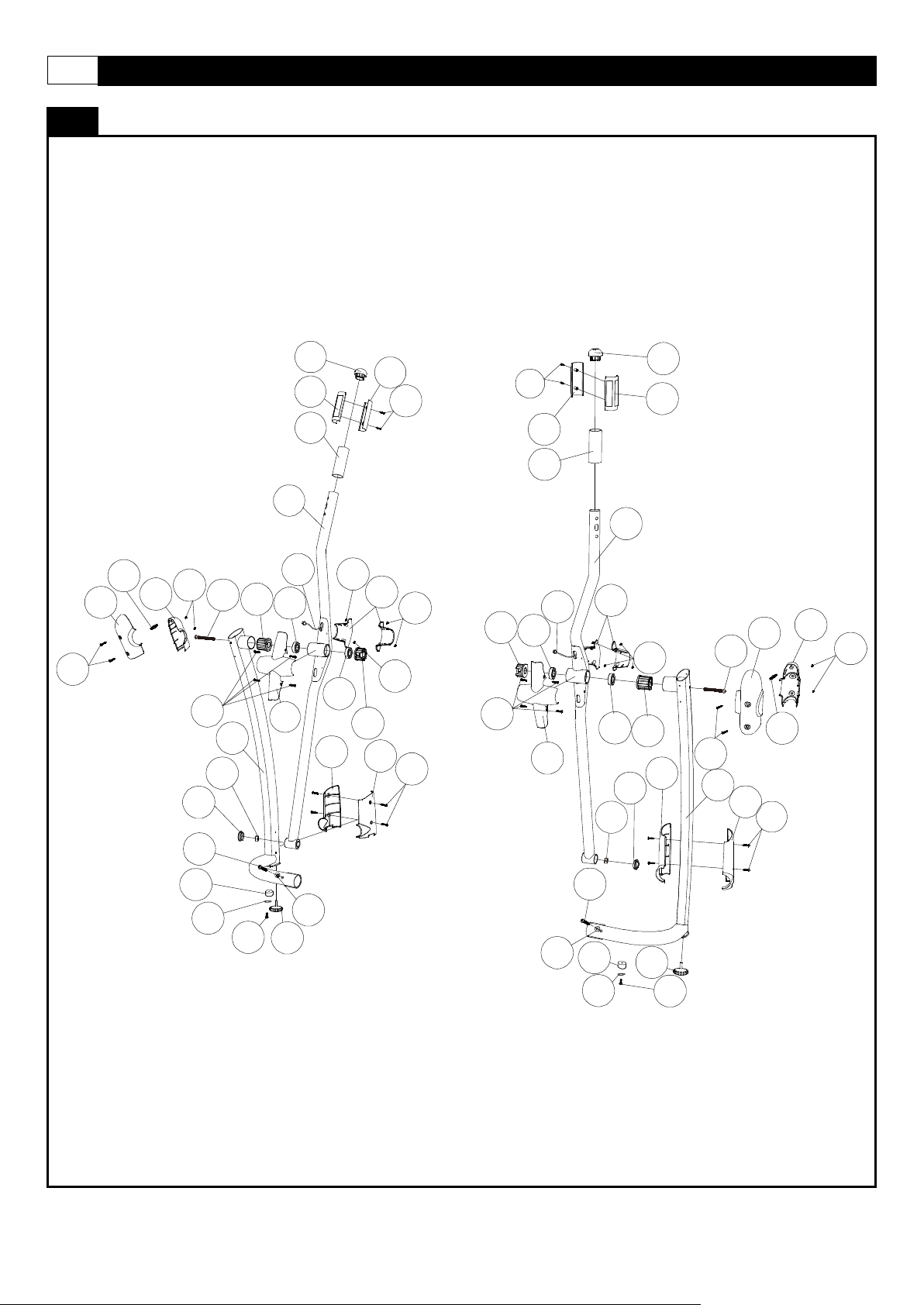
PARTS DIAGRAM
201
203
109
105
111
753
112
111
113
116
752
752
117
115
114
753
106
107
106
118
109
732
751
732
104
103
102
101
110
203
202
205
204
205
202
726
119
205
205
709
709
731
731
729
732
108
Page 10
10 SMOOTH CE3.6 ELLIPTICAL
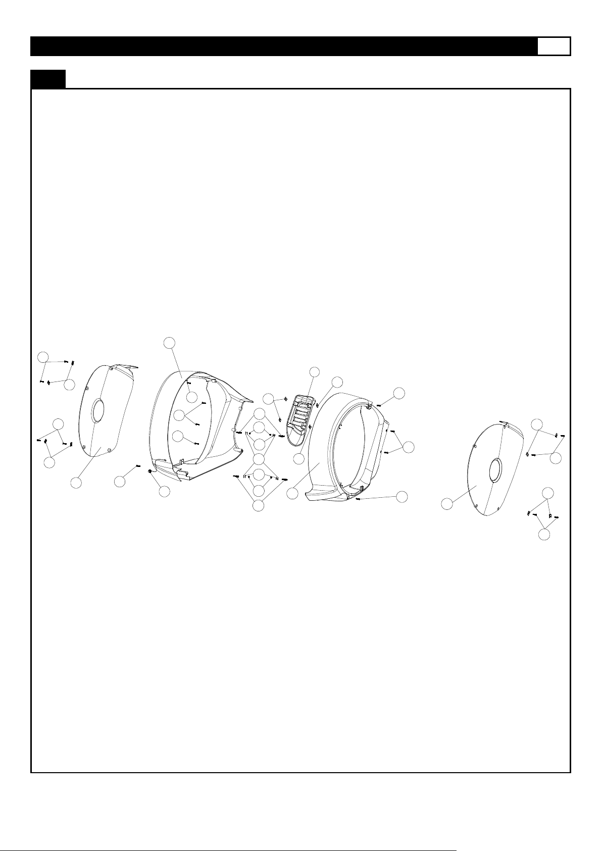
PARTS DIAGRAM
MOST OF THE PARTS SHOWN HERE HAVE BEEN PRE-ASSEMBLED.
708
320
318
708
728
710
303
320
732
314
315
304
315
317
732
313
728
728
710
317
313
316
308
314
313
316
307
302
311
726
306
312
305
310
726
309
319
319
306
305
308
307
726
726
726
726
726
321
321
318
754
726
754
726
716
716
722
722
719
719
309
310
312
301
311
728
313
726
Page 11
www.smoothfitness.com
11
PARTS DIAGRAM
MOST OF THE PARTS SHOWN HERE HAVE BEEN PRE-ASSEMBLED.
407
705
707
705
413
401
414
415
715
413
417
402
715
414
415
407
412
701
320
417705
716
726
726
716
417
726
417
403
403
320
701
412
404
404
707
405
718
404
404
405
705
406
706
715
408
409
706
408
715
409
718
755
737
737
420
421
420
421
718
406
718
726
755
Page 12
12 SMOOTH CE3.6 ELLIPTICAL
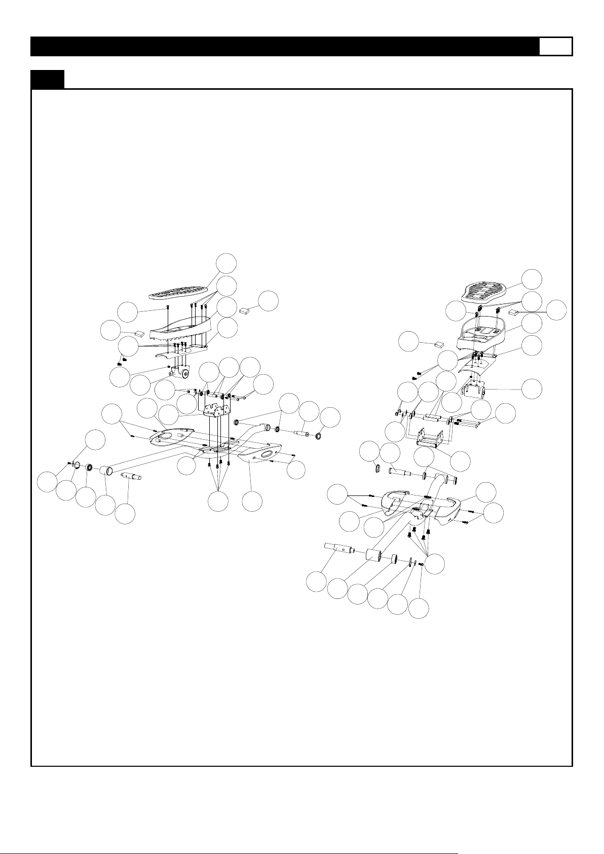
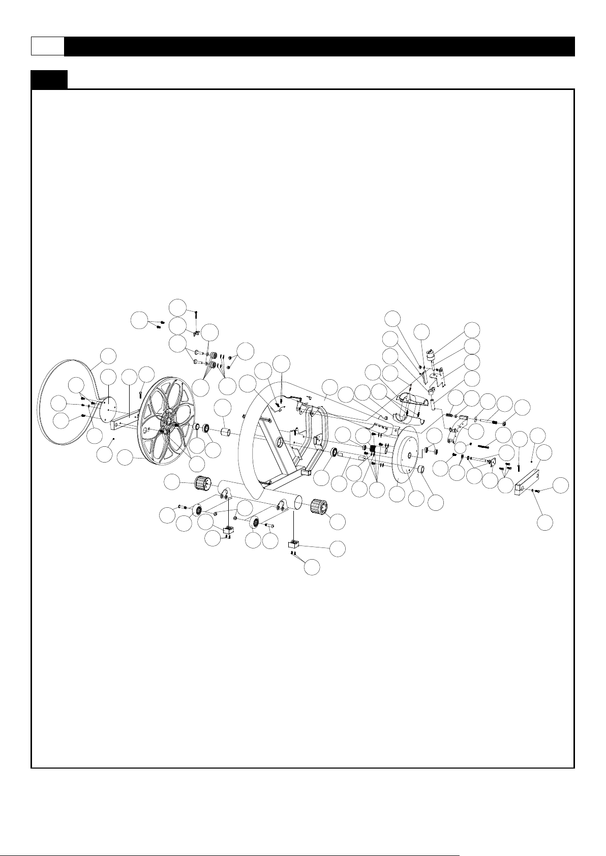
PARTS DIAGRAM
MOST OF THE PARTS SHOWN HERE HAVE BEEN PRE-ASSEMBLED.
725
715
705
705
745
504
747
503518
502
744
748
506
712
509
713
517
711
704
527
507
724
514
726
763
535
720
540
729
704
541
712
751
514
501
521
515
506
507
522
766
755
523
510
524
716
760
718
530
529
730
703
755
516
521
764
517
702
743
763
528
527
526
525
724
520
738
723
519
531
742
532
744
721
748
747
503
715
745
726
Page 13
www.smoothfitness.com
13
PARTS DIAGRAM
MOST OF THE PARTS SHOWN HERE HAVE BEEN PRE-ASSEMBLED.
607
726
726
604
726
601
727
606
727
606
727
606
606
606
603
761
870
762
754
762
761
870
602
726
727
726
605
606
727
606
727
Page 14

14 SMOOTH CE3.6 ELLIPTICAL
WIRE DIAGRAM
MOST OF THE PARTS SHOWN HERE HAVE BEEN PRE-ASSEMBLED.
205
205
205
205
204
106
107
106
321
321
321
321
204
522
522
522
540
540
607
607
607
Page 15

www.smoothfitness.com
ASSEMBLY
STEP 1:
709
X2
731
X2
729
X2
729
731
501
709
201
204
522
(A) Connect the 7pin Computer Wire – Middle (204) to the 7pin Computer
Wire – Lower (522).
(B) Attach the Console Support Upright (201) to the Main Frame (501) and
secure using the M10x94mm Bolt (709), 10.5x28x2mm Cup Washer
(731) and M10 Nut (729).
15
Page 16

16 SMOOTH CE3.6 ELLIPTICAL
ASSEMBLY
STEP 2:
301
201
302
321
205
(A) Slide the Acton Handlebar – Left (301) and Action Handlebar – Right (302) to the Console Support Upright (201)
(B) Connect the Hand Pulse Sensor Wire – Middle (205) to Hand Pulse Sensor Wire – Lower (321)
Page 17

www.smoothfitness.com
ASSEMBLY
STEP 3:
710
X2
722
X2
708
X2
710
201
303
708
722
(A) Attach the Left Upright and Right Upright to the Console Support Upright
(201), and secure using M8x65mm Bolt (710) on top of upright, M8x60mm
Bolt (708) and 8x21x2mm Cup Washer (722) on bottom of upright.
17
Page 18

18 SMOOTH CE3.6 ELLIPTICAL
ASSEMBLY
STEP 4:
701
X2
719
X2
B
A
719
302
C
401
701
(A) Slide the M14x91mm Bolt (701) through the Pedal Arm – Right (401) and
Action Handlebar – Right (302) and secure the M14 Nut (719) as shown.
Repeat the above procedure to assemble the Left side.
Page 19

www.smoothfitness.com
STEP 5:
320
320
402
320
302
401
301
(A) Attach the Pedal Arm Front Pivot Cover (320) into the ends of the Action
Handlebar – Right (302) and Pedal Arm – Right (401). Repeat the
procedure on the Pedal Arm – Left (402) and Action Handlebar – Left
(301).
320 X4
19
Page 20

20 SMOOTH CE3.6 ELLIPTICAL
ASSEMBLY
STEP 6:
730
X1
501
523
524
716
730
(A) Attach the Front Frame Cover – Upper (524) and Front Frame Cover –
Lower (523) to the Main Frame (501). Secure with Fixing Inserts (716)
and 4x50mm Bolt (730).
NOTE: The Fixing Insert (716) has been pre-assembled to Front Frame
Covers by factory.
Page 21

www.smoothfitness.com
STEP 7:
728
X8 732
X8
732
315
732
301
302
316
728
(A) Attach the Action Handlebar Cover (315) to the front side of Action
Handlebar – Right (302) and secure with four 4x15mm Screws (732).
Then attach two Action Handlebar Inside Covers (316) from the back side
of the Action Handlebar – Right (302) to the Action Handlebar Cover
(315). Secure the Action Handlebar Inside Covers using four 4x12mm
Screws (728). Repeat the procedure on the Action Handlebar – Left.
21
Page 22

22 SMOOTH CE3.6 ELLIPTICAL
ASSEMBLY
STEP 8:
726
X8
726
308
303
307
726
308
307
726
304
(A) Attach the Upright Lower Cover – Left (308) and Upright Lower Cover –
Right (307) to Right Upright (304) using four 4x19mm Screw (726).
Repeat this procedure on Left Upright (303) with Upright Lower Cover –
Left (308) and Upright Lower Cover – Right (307).
Page 23

www.smoothfitness.com
ASSEMBLY
STEP 9:
726
X4
726
305
306
306
305
726
726
(A) Attach the Upright Upper Cover #1 (305) and Upright Upper Cover #2 (306))
to Upright using one Fixing Insert (716) and four 4x19mm Screws (726).
NOTE: The Fixing Insert (716) has been pre-assembled onto Upright Upper
Cover #1 (305) by factory.
23
Page 24

24 SMOOTH CE3.6 ELLIPTICAL
ASSEMBLY
STEP 10:
726
X2
726
119
201
751
106
106
205
205
107
204
First make sure to connect the 7pin Computer Wire – Upper (107) with 7pin
Computer Wire – Middle (204) and Hand Pulse Sensor Wire – Upper (106)
with Hand Pulse Sensor Wire – Middle (205) as shown below.
(A) Attach the Computer to the Console Support Upright (201) using four M6 x
20mm Bolts (105).
(B) Attach the Console Back Cover (119) to the Console and secure using four
4x19mm Screws (726)
NOTE: Make sure all wires are recessed into the Console Hous i ng, do not tr ap
or pinch any of the wires.
Page 25

www.smoothfitness.com
iPod MOUNTING INSTRUCTION
iPod MOUNTING INSTRUCTION:
1. Attach your iPod into the dock
2. Rotate the iPod to lay on the bracket
3. Adjust the intensity of volume on computer buttons while playing music.
25
Page 26

26 SMOOTH CE3.6 ELLIPTICAL
LEVEL ADJUSTMENT
LEVEL ADJUSTM ENT:
To adjust the levelers follow these instructions:
You will need someone to help you with this procedure, as you will need to tip, the CE3.6 elliptical Trainer while
adjusting the levelers
Tip the AGILE Dynamic Motion Trainer to the lef t/r ig ht. You will then see the LE V EL ADJ UST ER S. These w ill need
to be screwed either in or out to level the trainer. Repeat for the other side. It may help to use a bubble level when
adjusting the level on your AGILE Dynamic Motion Trainer.
Page 27

www.smoothfitness.com
TRANSPORT INSTRUCTION
TRANSPORT INSTRUCTIONS:
To transport your CE3.6 elliptical Trainer simply lift the back end and roll it away to the desired location, as shown.
27
Page 28

28 SMOOTH CE3.6 ELLIPTICAL
MUSCLE CHART
Targeted muscle groups:
The exercise routine that is performed on this product will develop primarily lower body muscle groups. These muscle groups are
shown in gray color on the chart below.
MUSCLE GROUPS
A Shoulder muscles Calf muscles G
B Pectoral muscles Trapezius muscles H
C Bicep muscle Tricep muscles I
D Abdominal muscles Back muscles J
E Forearm muscles Gluteal muscles K
F Quadricep muscles Hamstring muscles L
Page 29

www.smoothfitness.com
STRETCHING ROUTINE
Warm up and cool down:
cool-down exercises on the following pages:
Slowly bend forward from
Lift your right shoulder up
Sit with the soles of your feet
Sit with your right leg
Open your arms to the side
Lean against a wall with your
Rotate your head to the right
for one count.
A successful exercise program consists of a warm-up, aerobic exercise, and a cool-down. Do the entire program at least two and
preferably three times a week, resting for a day between workouts. After several months, you can increase your workouts to four or
five times per week.
Warming up is an important part of your workout, and should begin every session. It prepares your body for more strenuous
exercise by heating up and stretching out your muscles, increasing your circulation and pulse rate, and delivering more oxygen to
your muscles. At the end of your workout, repeat these exercises to reduce sore muscle problems. We suggest the warm-up and
29
Toe Touch:
your waist, letting your back
and shoulders relax as you
stretch toward your toes.
Reach down as far as you
can and hold for 15 counts.
Inner Thigh Stretch:
together with your knees
pointing outward. Pull your
feet as close into your groin
as possible. Gently push
your knees towards the floor.
Hold for 15 counts.
Side Stretch:
and continue lifting them until
they are over your head.
Reach your right arm as far
upward toward the ceiling as
you can for one count. Feel
the stretch up your right side.
Repeat this action with your
left arm.
Shoulder Lift:
toward your ear for one
count. Then lift your left
shoulder up for one count as
you lower your right shoulder.
Hamstring Stretch:
extended. Rest the sole of
your left foot against your
right inner thigh. Stretch
toward your toe as far as
possible. Hold for 15 counts.
Relax and then repeat with
left leg extended.
Calf-Achilles Stretch:
left leg in front of the right
and your arms forward. Keep
your right leg straight and the
left foot on the floor; then
bend the left leg and lean
forward by moving your hips
toward the wall. Hold, and
then repeat on the other side
for 15 counts.
Head Roll:
for one count, feeling the
stretch up the left side of your
neck. Next, rotate your head
back for one count, stretching
your chin to the ceiling and
letting your mouth open.
Rotate your head to the left
for one count, and finally,
drop your head to your chest
Page 30

30 SMOOTH CE3.6 ELLIPTICAL
COMPUTER OPERATION
D
E
F
G
H
I
J
K
L
P
Q
R
S
T
U
INTENSITY LEVEL DOT
MATRIX
V
RPM
A
WEIGHT
RESISTANCE LEVEL
MODE BUTTON
RESISTANCE DOWN
M
START BUTTON
WATT
RPM DIAGRAM
GENDER
B
HEIGHT
PULSE
STOP BUTTON
ENTER BUTTON
N
RESISTANCE UP
SPEED
AGE
C
TIME
DISTANCE / PROGRAM
iPod VOL CONTROLS
FAN CONTROL
O
FAN INTENSITY
Page 31

www.smoothfitness.com
COMPUTER OPERATION
Whether you
want to lose weight, train for a sporting event, or simply maintain a healthy lifestyle, the MY SMOOTH
Virtual Fitness Trainer provides the tools, structure and support you need to be fit and live healthy. The
are proven to help you lose weight, improve your
health, and make positive steps to a healthier lifestyle. These five steps combined with the tools built
contained in your Smooth
*Not all Smooth Fitness products include the Smooth Customer Care Kit
Congratulations this product is equipped with the MY SMOOTH Virtual Fitness Trainer.
5 simple steps, outlined in the customer care kit*
31
into your online account, will provide you with a great start toward achieving your goals.
To set up your account, refer to the instructions in the Getting Started Guide
Fitness customer care kit or visit www.mysmoothtrainer.com
Page 32

32 SMOOTH CE3.6 ELLIPTICAL
COMPUTER OPERATION
A
B
C
C.
To record your exercise and health metrics, you must log on to www.mysmoothtrainer.com .
Then sync your MY Smooth Virtual Fitness Trainer USB device. Once complete simply plug in
the MY Smooth Virtual Fitness Trainer USB device to you compatible Smooth Fitness exercise
machine. Displayed on the equipm ent will be your name, weight height and age. Press
“START” button to begin your workout, the console will record your exercise data autom atic al ly,
every 20 seconds, to your MY Smooth Virtual Fitness Trainer USB device. After your exercise
session is complete, Insert the MY Smooth device in to the USB port of your PC or MAC to
upload your data to The MY Smooth Virtual Fitness Trainer online health management
program. The detailed reports show your exercise and health results, trends and
recommendations to better achieve and maintain your fitness goals.
USB Port Instruction
A. USB charging port. Charge you
favorite mobile device while you workout.
B. MY Smooth Virtual Fitness Trainer-
Record your fitness statistics.
Mp3 Jack- connects and listens to your
Audio device using a 2.5mm audio plug.
Page 33

www.smoothfitness.com
COMPUTER OPERATION
POWER ON
33
Please set your local time. Turn on the power switch, and computer will reset automatically and blinks “L1” around 2 seconds, after
a “Beep”, then please press INTENSITY UP and DOWN simultaneously, hold for 5 seconds, then the blink will guide you to set on
the display. Presses INTENSITY UP or DOWN to select correct time and date, press STOP/ENTER to do the next setting and also
save this memory in the end
Press the START button to quick-st ar t exercise.
Press any button to skip into program selection mode”U1”, and please refer to “PROGRAM MODE” for following operation.
After connecting the Adaptor, the LCD screen will light up.
To switch back to the power on status after the machine has already been used press the stop button twice.
QUICK START
When the c omp uter is in t he POW ER ON STATU S, p re ss t he s tart butt on t o act iva te th e QUICK START program, the TIME, DISTANCE
and CALORIES will count up when you start exercising.
SLEEP MODE
When the power is ON the computer will automatically enter SLEEP MODE if it is left idle for 3 minutes without receiving any input, press
any button to return to power on status when the computer is in the SLEEP MODE.
PAUSE MODE
While in the PROGRAM, without pedalling the machine for 30 seconds, the console will enter the PAUSE MODE. During the PAUSE
MODE, if you start pedalling the machine or press the START button, the console will return to the PROGRAM MODE and continue the
original program. Press the STOP button to PAUSE the program, press STOP button twice and the LCD will reset to POWER ON status.
Page 34

34 SMOOTH CE3.6 ELLIPTICAL
COMPUTER OPERATION
FAN FUNCTION:
SPEED,
them for 3 seconds.
or start pedaling to resume the program
To activate the fan press the fan button to turn on ,pressing the fan button will also adjust the fan speed
First Press:
When adjusting the angle of the fan be sure not to over rotate. This feature is designed to tilt 25 degrees up and 25 degrees
down. Over rotation may damage the fan assembly.
POWER ON
After connecting the Adaptor, switch the power button on. The LCD screen will light up.
To switch back to the power on status after the machine has already been used press the stop key twice.
QUICK START
When the computer is in the POWER ON STATUS, press the start button to activate the QUICK START program, the TIME,
DISTANCE and CALORIES will count up when you start exercising.
SLEEP MODE
The computer will automatically enter SLEEP MODE if left idle for 3 minutes without any input in POWER ON status. When the
computer is in SLEEP MODE, press any button or pedal and the machine will return to POWER ON status. You can turn SLEEP MODE
off but the console will be drawing power indefinitely if it plugged in to keep the LCD lit. To turn SLEEP MODE off, get the c ons ole to
POWER ON status then press RESISTANCE UP/DOWN and STOP/ENTER three buttons on the computer and hold
The computer will sound one short beep and “Sr 1” blinking. Press START button to enter conversion SLEEP MODE function. After
Press the START button the computer will display either “On” or “Off” blinking then press RESISTANCE UP/DOWN button to switch
between “On” and “Off” then press STOP/ENTER button twice to return to the POWER ON status.
PAUSE/STOP:
During the workout, press STOP button or STOP pedaling for 30 seconds to enter PAUSE status. The RESISTANCE LEVEL Dot Matrix
display will show “PAUSE”. All figures on the console will be frozen. Press the START button
and all the display will continue the performance until the program finishes. If you leave the pedal stopped for over 3 minutes or press
the STOP button, all the data will return to 0 and the computer will return to POWER ON status.
ENGLISH/METRIC CONVERSION:
The Crosstrainer computer display can show ENGLISH and METRIC information. Computer display “MPH” is ENGLISH status and
display “KM/H” is METRIC status. The factory should have the proper setting on this for different markets. In case that the crosstrainer
needs to be converted between METRIC and ENGLISH readout, please follow the procedure as below:
1. Set the POWER SWITCH to ON. Then press RESISTANCE UP/DOWN and STOP/ENTER three buttons on the computer and hold
them for 3 seconds. The computer will sound one short beep and “Sr 1” blinking. Press RESISTANCE UP/DOWN button to select
display “Sr 2” blinking then press START button to enter conversion M ET RIC /EN G LISH function.
2. After Press the START button the computer will display either “KM/H” or “ MPH” blinking then press RESISTANCE UP/DOWN
button to switch between “KM/H” and “MPH” then press STOP/ENTER button twice return to the POWER ON status.
Second Press: Third Press: Fourth Press: STOP
Page 35

www.smoothfitness.com
COMPUTER OPERATION
Main Individual custom program
The target time of the program will count down from the preset. The
ver the sensors. It will take a few seconds for your pulse rate to be displayed on the console. To keep monitoring, keep
ith the sensors or not enough of your palm on the
Press START button to start the target distance program.
Press the START button again to begin the exercise program. The LCD display will show the INTENSITY WATT and TIME status as the
user set it. Press RESISTANCE UP/DOWN to adjust the resistance.
DISTANCE, CALORIES display will count up from 0. To pause the program while exercising, press the STOP/ENTER button. To quit the
program, press the STOP/ENTER button twice. At the end of the program when the target has been achieved, the computer will beep
then return POWER ON status.
Heart Rate Operation
The Sanibel comes with EKG hand pulse sensors which can be found on the handlebars. To operate pulse rate function, place the palms
of your hands o
gripping the sensors, if the readings are intermittent you may not have full contact w
sensor. Remove your hand and place it over the sensor again.
PROGRAM OPERATION INSTRUCTION:
At POWER ON status, press STOP/ENTER button to enter preset PROGRAM MODE and to set user parameters.
SET UP USER CODE:
At first, the LCD will show a blinking U1, and will also display only factory default setting values for user HEIGHT, WEIGHT, AGE and
GENDER. Press the RESISTANCE UP/DOWN buttons to choose the User ID from U1 to U9 and press the STOP/ENTER buttons to
assign the user ID shown.
HEIGHT set up – After the User ID set up procedure, the computer will display the default “170(cm)/67” or previous setting and begin
blinking. Press the RESISTANCE UP/DOWN button to adjust the user height information then press STOP/ENTER to confirm.
WEIGHT set up – After the User HEIGHT confirmation procedure, the computer will display the default “68(kgs)/150(lbs) or previous
setting and begin blinking. Press the RESISTANCE UP/D O WN butto n to adjust the user weight information then press STO P/E NTE R to
confirm.
AGE set up – After the WEIGHT set up procedure, the computer will display the default “35” or previous setting and begin blinking.
Press the RESISTANCE UP/DOWN button to adjust the user age information then press STOP/ENTER to confirm.
GENDER set up – After the AGE set up procedure, the computer will display the default “man” or previous setting and begin blinking.
Press the RESISTANCE UP/DOWN button to adjust the user gender then press STOP/ENTER to confirm.
PROGRAM 1 – TARGET TIME
After selecting this program, the TIME display shows the factory default setting “32:00”. Press RESISTANCE UP/DOWN
button to adjust the target time and press STOP/ENTER to confirm. Press START button to start the target time program. Time counts
down to 0, Distance and Calories count up. Press RESISTANCE UP/DOWN to adjust the resistance.
PROGRAM 2 – TARGET DISTANCE
After selecting this program, the DISTANCE display shows factory default setting 3.2mph or 5.0km/h. Press RESISTANCE UP/DOWN
button to adjust the target distance and press STOP/ENTER to confirm.
Distance counts down to 0, Time and Calories count up. Press RESISTANCE UP/DOWN to adjust the resistance.
PROGRAM 3 – TARGET CALORIES
After selecting this program, the CALORIES display shows factory default setting “50”. Press RESISTANCE UP/DOWN button to adjust
the target calories and press STOPE/ENTER to confirm. Press START button to start the target calories program. Calories counts down
to 0, Time and Distance count up. Press RESISTANCE UP/DOWN to adjust the resistance.
35
Page 36

36 SMOOTH CE3.6 ELLIPTICAL
COMPUTER OPERATION
PROGRAM 4 – FAT BURNING
target time and press STOP/ENTER to confirm. Press START button to start the FAT BURNING program. Time counts down to 0,
P/DOWN to adjust the
1st
Segment
2nd
Segment
3rd
Segment
4th
Segment
5th
Segment
13th
Segment
14th
Segment
15th
Segment
16th
Segment
RESISTANCE/Level
L1
L3
L7
L9
L9
L9
L7
L3
L1
Level
1 1 1 1 1 1 1 1 1
TIME display shows factory default
own to 0, Distance and Calories count up. Dot Matrix display shows
TIME
/level
LEVEL
L1
L1
L9
L9
L1
L1
L9
L9
L1
L2
L2
L10
L10
L2
L2
L10
L10
L2
L3
L3
L11
L11
L3
L3
L11
L11
L3
L4
L4
L12
L12
L4
L4
L12
L12
L4
L5
L5
L13
L13
L5
L5
L13
L13
L5
L6
L6
L14
L14
L6
L6
L14
L14
L6
L7
L7
L15
L15
L7
L7
L15
L15
L7
L8
L8
L16
L16
L8
L8
L16
L16
L8
After selecting this program, the TIME display shows factory default setting “16:00”. Press RESISTANCE UP/ DOWN button to adjust the
Distance and Calories count up. Dot Matrix display shows the pre-set RESISTANCE. Press RESISTANCE U
resistance.
Fat Burning Program provides 1 to 16 one minute segments.
TIME/zone
………
PROGRAM 5 – INTERVAL INTENSITY
After selecting this program, the TIME display shows “L1”. This indicates the intensity level for the intervals. Use the RESISTANCE
UP/DOWN buttons to change the intensity then press STOP/ENTER button to enter to confirm.
setting “32:00”. Press RESISTANCE UP/DOWN button to adjust the target time and press STOP/ENTER to confirm. Press START
button to start the INTERVAL INTENSITY program. Time counts d
the pre-set INTENSITY profile. Press RESISTANCE UP/DOWN to adjust the resistance.
This program has a maximum of 16 segments. If the program length exceeds 16 minutes the time entered will
average out over 16 segments
/zone
INTENSITY
PROGRAM 6 – RANDOM
After the user has selected “P6- RANDOM program”, The TIME will show the workout time setting of “32:00”, Press the RESISTANCE
UP /DOWN button to adjust workout time, Then press the STOP/ENTER button to confirm. Press the START button to begin the exercise
program. This program consist s of 16 segments if the time entered exceeds 16 minutes the time is averaged over the 16 segments. The
resistance display will show “1”. To increase or decrease the resistance while exercise, press the RESISTANCE UP/DOWN button. The
target time will count down, the DISTANCE and CALORIES will count up from 0.
To pause the program while exercising, press the STOP/ENTER button, To quit out the program, press the STOP/ENTER button twice.
At the end of the program when the target has been achieved, the computer will beep.
1st
Segment
2nd
Segment
3rd
Segment
4th
Segment
5th
Segment
6th
Segment
7th
Segment
8th
Segment
Page 37

www.smoothfitness.com
COMPUTER OPERATION
PROGRAM 7 – ENDURANCE
UP/DOWN button to adjust the workout level and press
time and press STOP/ENTER to confirm. Press START button to start the ENDURANCE program. Time counts down to 0, Distance and
TIME
/level
LEVEL
L1
L1
L1
L3
L3
L4
L4
L5
L5
L6
L6
L7
L7
L9
L9
L1
L1
L2
L2
L2
L4
L4
L5
L5
L6
L6
L7
L7
L8
L8
L10
L10
L2
L2
L3
L3
L3
L5
L5
L6
L6
L7
L7
L8
L8
L9
L9
L11
L11
L3
L3
L4
L4
L4
L6
L6
L7
L7
L8
L8
L9
L9
L10
L10
L12
L12
L4
L4
L5
L5
L5
L7
L7
L8
L8
L9
L9
L10
L10
L11
L11
L13
L13
L5
L5
L6
L6
L6
L8
L8
L9
L9
L10
L10
L11
L11
L12
L12
L14
L14
L6
L6
L7
L7
L7
L9
L9
L10
L10
L11
L11
L12
L12
L13
L13
L15
L15
L7
L7
L8
L8
L8
L10
L10
L11
L11
L12
L12
L13
L13
L14
L14
L16
L16
L8
L8
WATTS display shows factory default setting “110”. Press RESISTANCE
Press START button to start the
set INTENSITY profile.
The TARGET HEART RATE CONTROL program is designed to keep the user training at their chosen heart rate level to achieve the
toring device must be used for this program. The equipment provides a standard contact
to monitor the user heart rate during the workout. A wireless chest belt transmitter is highly
ncouraged to consult with a doctor or personal Training consultant to more accurately estimate their SAFE
UP/DOWN button to adjust the target heart rate then press the
ounts down from “3.00” to “0:00”. Intensity Level Profile displays “WARM UP” 3 times. During the
(if necessary) 3 minute warm up program. If user’s actual heart rate fails to reach 65% of the MAXIMUM SAFE HEART RATE after
turn to POWER ON status in 10
After selecting this program, the TIME display shows “L1”. Press RESISTANCE
STOP/ENTER to confirm. TIME display shows factory default setting “32:00”. Press RESISTANCE UP/DOWN button to adjust the target
Calories count up. Dot Matrix display shows the pre-set RESISTANCE profile. Press RESISTANCE UP/DOWN to adjust the resistance.
This program has a maximum of 16 segments. If the program length exceeds 16 minutes the time entered will
average out over 16 segments.
37
INTENSITY
PROGRAM 8 – WATTS CONTROL
The function of Watts Control program is to allow the user to set a desired workout load (watts). The user’s workout load is controlled
automatically by increasing or decreasing the resistance as the user changes their stride cadence (RPM). The intensity will be reduced
when user increases RPM and the RESISTANCE will be increased when the user decreases the RPM. After selecting this program
press STOP/ENTER to continue the set up procedure.
UP/DOWN button to adjust the target Watts and press STOP/ENTER to adjust TIME. TIME display shows factory default setting “16:00”.
Press RESISTANCE UP/DOWN button to adjust the target Time and press STOP/ENTER to confirm.
WATTS program. Time counts down to 0, Distance and Calories count up. Dot Matrix display shows the prePress RESISTANCE UP/DOWN to adjust the resistance.
PROGRAM 9 – TARGET HEART RATE CONTROL PROGRAM
proper workout result. A heart rate moni
handgrip on the moving handle bar to sense the user heart beat during the workout. The user must hold the contact handgrips on the
moving handle bar constantly in order
recommended for this program.
IMPORTANT: The console software will calculate the user’s SAFE MAXIMUM HEART RATE based on the formula: (220pbmAGE). User’s are e
MAXIMUM HEART RATE in order to workout safely.
PULSE display shows the calculated TARGET HEART RATE based on the user age setting from the above step. The TARGET HEART
RATE = 85% MAXIMUM SAFE HEART RATE. Press RESISTANCE
STOP/ENTER bottom to confirm.
After adjust the TARGET HEART RATE, the TIME display shows factory default setting “32:00”. Press RESISTANCE UP/DOWN bu tton
to adjust the target time and press STOP/ENTER to confirm.
Press the START button to start the 3 minute WARM UP. The purpose of warm up program is to bring the user’s heart rate to 65% of the
MAXIMUM SAFE HEART RATE. Time c
WARM UP, if the actual heart rate is less than 65% of the user’s MAXIMUM SAFE HEART RATE, the intensity level will be increased by
1 level every 30 seconds. If the actual heart rate reaches 65% MAXIMUM SAFE HEART RATE twice within the warm up, the HEART
RATE CONTROL program will start after finished 3minute WARM UP.
If user’s actual hear rate fails to reach 65% of MAXIMUM SAFE HEART RATE during the warm up, the user will be placed into a 2nd or
3rd
the 3rd 3 warm up program, the INTENSITY LEVEL PROFILE dot matrix will display “FAIL” then re
seconds.
/zone
1st
Seg.
2nd
3rd
4th
5th
6th
7th
8th
9th
10th
11th
12th
13th
14th
Seg.
Seg.
Seg.
Seg.
Seg.
Seg.
Seg.
Seg.
Seg.
Seg.
Seg.
Seg.
Seg.
15th
Seg.
16th
Seg.
Page 38

38 SMOOTH CE3.6 ELLIPTICAL
COMPUTER OPERATION
Once the user successfully enters the HEART RATE CONTROL program, the computer will actively adjust the motion level and intensity
r is consistently below the TARGET HEART RATE, the MOTION LEVEL
ON LEVEL will decrease 1 level every 30 seconds until level 1 and
inutes, or the time counts down to “0:00”, the heart rate control
ENTER button, C1 will display and flash on the LCD. The program can
After setting up
level to keep the users at the TARGET HEART RATE. If the use
will increase 1 level every 30 seconds until reach LEVEL 12 and then the INTENSITY LEVEL will increase 1 level every 30 seconds. If
the user reaches and exceeds the TARGET HEART RATE, the MOTI
then the INTENSITY LEVEL will decrease 1 level every 30 seconds. The program will continue until the time runs out. If the user’s
heart rate continues to exceed the TARGET HEART RATE for 3 m
program will stop and start the 1 minute COOL DOWN function. Time counts down from “1:00” and RESISTANCE LEVEL at level 1.
P10: CUSTOMER COURSE
When the user selects P10 CUSTOM program and press’s STOP/
allow user to create 5 individual custom programs and store the settings for repeated workouts. To select the program from C1 to C5,
press the RESISTANCE UP/DOWN button. Press STOP/ENTER button and hold it for 3 seconds to confirm the selection and then
continues to set up. When the user selects one custom program and enter to set up, the user comes into the INTENSITY, WATT, and
TIME setting mode. In the display the first minute is flashing. Use RESISTANCE UP/DOWN button to adjust the INTENSITY and WATTs.
Then press the STOP/ENTER button to reserve the setting and continue to next minute setting of the program, etc.
above item, press the STOP/ENTER button and hold it for 3 seconds to confirm ,and then press START button to activate status. The
maximum workout time of each user program is 60 minutes.
Page 39

www.smoothfitness.com
COMPUTER OPERATION
Heart Rate Training
rate within which to train in order that you may improve your fitness at a
on the next page is a rough guide to determine the level at which you should
20
95
90
105
115
125
135
145
155
165
175
185
195
205
25 30 35 40 45 50 55 60 65 70
Age (years)
W
a
r
m
U
p
/
C
o
o
l
D
o
w
n
Fat Burning
Aerobic
Advance Per f ormance
Heartrate (beats per min)
!
To maximize your results from training it is essential to monitor the intensity of your workout through your heart rate.
It is imperative that you accurately determine the target pulse
safe, comfortable and sustainable level. The following table
be exercising based upon your maximum heart rate (MHR).
39
You can calculate the target-heartrate for your training as follows:
Maximum heartrate = 220 minus age
For the different trainingtargets you should train with the following percentage of your maximum heartrate:
Health/Fat Burning: 65 – 75% of your max. heartrate
Fitness/Bodyshaping: 75 – 85% of your max. heartrate
Performance: 85 - 95% of your max. heartrate
Example:
You are 25 years old and want to train for the target Fitness:
Your target-heartrate should be between 146 and 166 beats per minute.
This information is for your reference only. To determine your individual training intensity or in case
you should have health restrictions please consult your physician before starting exercising.
220 – 25 = 195
75% of 195 = 146,25
85% of 195 = 165,75
Heart Rate diagram
Page 40

40 SMOOTH CE3.6 ELLIPTICAL
WARRANTY
Model Name
Frame
Brake
Parts & Electronics
Labor
CE-3.6i USA Only
Lifetime
Lifetime
5 years
2 years
CE-3.6i Canada
Lifetime
Lifetime
5 years
1 year
LIMITED HOME USE WARRANTY – SMOOTH FITNESS Elliptical Warranty
Warranty Coverage: Smooth Fitness, Inc. ("Smooth Fitness") warrants to the original owner that each new product to be free from defects in
workmanship and material, under normal use and conditions.
Period of Coverage: The Warranty on this product runs from the date of original purchase using the following schedule:
Labor: Smooth Fitness will reimburse for labor costs for Two (2) years*. Smooth Fitness reserves the right to either:
Hire and reimburse an independent service technician who will come into the home for the repair,
OR
In the event that there is not an available certified Smooth Fitness service technician, Smooth will send the part directly to the consumer and will
pay $75 US per occurrence for the labor costs of such repair. If multiple repair attempts must be made for one reported problem, Smooth will only
reimburse once per occurrence.
Smooth Fitness reserves the right to inspect damaged parts for misuse. Your Original Receipt is proof of purchase and should be kept with the
product manual. You may be required to show proof of purchase prior to warranty service being initiated.
Remedy Provided by Smooth Fitness: Smooth Fitness will provide a replacement part free of charge if a defect is found during the Warranty
period. Smooth Fitness may at its discretion, choose to provide any of following parts or repair options. In the event that a part is determined in
need of replacement, upon receipt of the part by Smooth Fitness, Smooth Fitness may send out the part by UPS ground or another such carrier
directly to the customer’s home.
Any redemption may be by repair or replacement of the affected parts and/or product at the sole discretion of Smooth Fitness, by personnel
approved by Smooth Fitness.
Parts repaired or replaced pursuant to this Warranty shall be warranted for the unexpired portion of the Warranty applying to the original product.
Any technical advice furnished before or after delivery in regard to the use or application of Smooth Fitness products is furnished without charge
and on the basis that it represents Smooth Fitness' best judgment under the circumstances but that the advice is used at your sole risk.
Procedure for Obtaining Your Remedy Under This Warranty: To obtain service on a Smooth Fitness product, call Smooth Fitness. In the
instance that service is not available in an area, Smooth Fitness, at its discretion, can either 1) find a service technician in your area to perform
warranty service, 2) have a local dealer perform warranty service, or 3) send the warranty parts to you and reimburse as described above. To
help the technician assist you, please have the following inform ation ready:
• Model name or number from the cover of the manual;
• Serial number located on the frame of the unit; and
• The part description and the order number.
Limitations on Warranty: This Warranty does not cover any problems, damages or failures that are caused by accident, improper assembly,
failure to observe cautionary labels on the product, failure to operate the product correctly, power grid failures or spikes from your local electrici ty
provider, abuse or freight damage. Smooth Fitness does not warrant against any damage or defects that may result from repair or alterations
made to the product by an unauthorized repair facility. In order for this warranty to be valid, all Smooth Fitness and EVO Fitness exercise
equipment must be stored and used in a fully finished and livable room within the residence (not including an indoor swimming pool room).
This Warranty shall terminate if you sell or otherwise transfer this product. This Warranty does not apply to any product shipped or handled
outside of the United States or Canada. This Warranty does not apply if the product is used as a rental product or in commercial use.
Consequential and incidental damages are not recoverable under this Warranty. (Some states do not allow the exclusion or limitat i on of incidental
or consequential damages, so the above limitation or exclusion may not apply to you.)
THIS WARRANTY IS EXPRESSLY IN LIEU OF ALL OTHER EXPRESS WARRANTIES. ALL IMPLIED WARRANTIES,
INCLUDING WARRANTIES OF MERCHANTABILITY OR FITNESS FOR AN Y PAR TICULAR PURPOSE, ARE LIMITED IN DURATION TO Two
(2) YEARS* FROM THE EFFECTIVE DATE OF THIS WARRANTY. SMOOTH FITNESS IS NOT
LIABLE FOR CONSEQUENTIAL OR INCIDENTA L DAMAGES RESULTING FROM ANY DEFECT IN PARTS NOR FOR
ANY BREACH OF EXPRESS OR IMPLIED WARRANTIES. SMOOTH FITNESS' SOLE LIABILITY UNDER THIS
WARRANTY IS LIMITED TO THE TERMS DESCRIBED IN THIS FORM. THIS WARRANTY GIVES YOU SPECIFIC LEGAL
RIGHTS, AND YOU MAY ALSO HAVE OTHER RIGHTS WHICH VARY FROM STATE TO STATE.
*Two year labor is valid only with the continental United States; Canadian labor warranties are valid for the period of 1 year from date of
purchase.
FORM WS-1 (rev. 03/2008)
Page 41

www.smoothfitness.com
41
Smooth Fitness
780 5
th
Ave
King of Prussia, PA 19406
Toll Free Customer Service:
1.888.800.1167
Website:
www.smoothfitness.com
 Loading...