


 Loading...

EZ ConnectTM g 108 Mbps
Wireless AP
User Guide
From SMC’s EZ line of low-cost workgroup LAN solutions
38 Tesla |
July 2005 |
Irvine, CA 92618 |
Revision #: R01, F1.0 |
Phone: (949) 679-8000 |
|
Copyright
Information furnished by SMC Networks, Inc. (SMC) is believed to be accurate and reliable. However, no responsibility is assumed by SMC for its use, nor for any infringements of patents or other rights of third parties which may result from its use. No license is granted by implication or otherwise under any patent or patent rights of SMC. SMC reserves the right to change specifications at any time without notice.
Copyright © 2005 by SMC Networks, Inc.
38 Tesla
Irvine, CA 92618
All rights reserved.
Trademarks:
SMC is a registered trademark; and EZ Connect is a trademark of SMC Networks, Inc. Other product and company names are trademarks or registered trademarks of their respective holders.
COMPLIANCES
Federal Communication Commission Interference
Statement
This equipment has been tested and found to comply with the limits for a Class B digital device, pursuant to Part 15 of the FCC Rules. These limits are designed to provide reasonable protection against harmful interference in a residential installation. This equipment generates, uses and can radiate radio frequency energy and, if not installed and used in accordance with the instructions, may cause harmful interference to radio communications. However, there is no guarantee that interference will not occur in a particular installation. If this equipment does cause harmful interference to radio or television reception, which can be determined by turning the equipment off and on, the user is encouraged to try to correct the interference by one of the following measures:
•Reorient or relocate the receiving antenna
•Increase the separation between the equipment and receiver
•Connect the equipment into an outlet on a circuit different from that to which the receiver is connected
•Consult the dealer or an experienced radio/TV technician for help
This device complies with Part 15 of the FCC Rules. Operation is subject to the following two conditions: (1) This device may not cause harmful interference, and
(2) this device must accept any interference received, including interference that may cause undesired operation.
FCC Caution: Any changes or modifications not expressly approved by the party responsible for compliance could void the user's authority to operate this equipment.
IMPORTANT NOTE:
IEEE 802.11b or 802.11g operation of this product in the U.S.A. is firmware-limited to channels 1 through 11.
i
COMPLIANCES
Industry Canada Statement
Operation is subject to the following two conditions:
This device may not cause interference and this device must accept any interference, including interference that may cause undesired operation of the device
This device has been designed to operate with an antenna having a maximum gain of 1.5 dBi.
Antenna having a higher gain is strictly prohibited per regulations of Industry Canada. The required antenna impedance is 50 ohms.
To reduce potential radio interference to other users, the antenna type and its gain should be so chosen that the EIRP is not more than required for successful communication.
EC Declaration of Conformity 
SMC contact for these products in Europe is:
SMC Networks Europe,
Edificio Conata II,
Calle Fructuos Gelabert 6-8, 2o, 4a,
08970 - Sant Joan Despi,
Barcelona, Spain.
Marking by the above symbol indicates compliance with the Essential Requirements of the R&TTE Directive of the European Union (1999/5/EC). This equipment meets the following conformance standards:
•EN 300 328-1 December 2001 V1.3.1
•EN 300 328-2 December 2001 V1.2.1
•EN 301 489-1 September 2001 V1.4.1
•EN 301 489-17 September 2000 V1.2.1
•EN 60950 January 2000
ii
COMPLIANCES
Countries of Operation & Conditions of Use in the European
Community
This device is intended to be operated in all countries of the European Community. Requirements for indoor vs. outdoor operation, license requirements and allowed channels of operation apply in some countries as described below:
Note: The user must use the configuration utility provided with this product to ensure the channels of operation are in conformance with the spectrum usage rules for European Community countries as described below.
•This device requires that the user or installer properly enter the current country of operation in the command line interface as described in the user guide, before operating this device.
•This device will automatically limit the allowable channels determined by the current country of operation. Incorrectly entering the country of operation may result in illegal operation and may cause harmful interference to other system. The user is obligated to ensure the device is operating according to the channel limitations, indoor/outdoor restrictions and license requirements for each European Community country as described in this document.
•This device may be operated indoors or outdoors in all countries of the European Community using the 2.4 GHz band: Channels 1 - 13, except where noted below.
-In Italy the end-user must apply for a license from the national spectrum authority to operate this device outdoors.
-In Belgium outdoor operation is only permitted using the 2.46 - 2.4835 GHz band: Channel 13.
-In France outdoor operation is only permitted using the 2.457 - 2.472 GHz band: Channels 10 - 13.
iii

COMPLIANCES
Declaration of Conformity in Languages of the European
Community
English |
Hereby, SMC Networks, declares that this Radio LAN device is in |
|
compliance with the essential requirements and other relevant |
|
provisions of Directive 1999/5/EC. |
|
|
Finnish |
Valmistaja SMC Networks vakuuttaa täten että Radio LAN device |
|
tyyppinen laite on direktiivin 1999/5/EY oleellisten vaatimusten ja |
|
sitä koskevien direktiivin muiden ehtojen mukainen. |
|
|
Dutch |
Hierbij verklaart SMC Networks dat het toestel Radio LAN device |
|
in overeenstemming is met de essentiële eisen en de andere |
|
relevante bepalingen van richtlijn 1999/5/EG |
|
Bij deze SMC Networks dat deze Radio LAN device voldoet aan |
|
de essentiële eisen en aan de overige relevante bepalingen van |
|
Richtlijn 1999/5/EC. |
|
|
French |
Par la présente SMC Networks déclare que l'appareil Radio LAN |
|
device est conforme aux exigences essentielles et aux autres |
|
dispositions pertinentes de la directive 1999/5/CE |
|
|
Swedish |
Härmed intygar SMC Networks att denna Radio LAN device står |
|
I överensstämmelse med de väsentliga egenskapskrav och |
|
övriga relevanta bestämmelser som framgår av direktiv 1999/5/ |
|
EG. |
|
|
Danish |
Undertegnede SMC Networks erklærer herved, at følgende |
|
udstyr Radio LAN device overholder de væsentlige krav og |
|
øvrige relevante krav i direktiv 1999/5/EF |
|
|
German |
Hiermit erklärt SMC Networks, dass sich dieser/diese/dieses |
|
Radio LAN device in Übereinstimmung mit den grundlegenden |
|
Anforderungen und den anderen relevanten Vorschriften der |
|
Richtlinie 1999/5/EG befindet". (BMWi) |
|
Hiermit erklärt SMC Networks die Übereinstimmung des Gerätes |
|
Radio LAN device mit den grundlegenden Anforderungen und |
|
den anderen relevanten Festlegungen der Richtlinie 1999/5/EG. |
|
(Wien) |
|
|
Greek |
|
|
|
iv

|
COMPLIANCES |
|
|
Italian |
Con la presente SMC Networks dichiara che questo Radio LAN |
|
device è conforme ai requisiti essenziali ed alle altre disposizioni |
|
pertinenti stabilite dalla direttiva 1999/5/CE. |
|
|
Spanish |
Por medio de la presente SMC Networks declara que el Radio |
|
LAN device cumple con los requisitos esenciales y cualesquiera |
|
otras disposiciones aplicables o exigibles de la Directiva 1999/5/ |
|
CE |
|
|
Portuguese |
SMC Networks declara que este Radio LAN device está |
|
conforme com os requisitos essenciais e outras disposições da |
|
Directiva 1999/5/CE. |
|
|
Safety Compliance
Underwriters Laboratories Compliance Statement
Important! Before making connections, make sure you have the correct cord set. Check it (read the label on the cable) against the following:
Operating Voltage |
Cord Set Specifications |
|
|
120 Volts |
UL Listed/CSA Certified Cord Set |
|
|
|
Minimum 18 AWG |
|
|
|
Type SVT or SJT three conductor cord |
|
|
|
Maximum length of 15 feet |
|
|
|
Parallel blade, grounding type attachment plug |
|
rated 15 A, 125 V |
|
|
240 Volts (Europe only) |
Cord Set with H05VV-F cord having three |
|
conductors with minimum diameter of 0.75 mm2 |
|
IEC-320 receptacle |
|
|
|
Male plug rated 10 A, 250 V |
|
|
The unit automatically matches the connected input voltage. Therefore, no additional adjustments are necessary when connecting it to any input voltage within the range marked on the power adapter.
Information for Power Source
This unit is to be used with an external power adaptor of a Class 2 or level 3 type and Approved type suitable for use in the North America of equipment installation, having an output voltage rating of 5 V dc, and output current rating of 1.0A or equivalent.
v
COMPLIANCES
Wichtige Sicherheitshinweise (Germany)
1.Bitte lesen Sie diese Hinweise sorgfältig durch.
2.Heben Sie diese Anleitung für den späteren Gebrauch auf.
3.Vor jedem Reinigen ist das Gerät vom Stromnetz zu trennen. Verwenden Sie keine Flüssigoder Aerosolreiniger. Am besten eignet sich ein angefeuchtetes Tuch zur Reinigung.
4.Die Netzanschlu ßsteckdose soll nahe dem Gerät angebracht und leicht zugänglich sein.
5.Das Gerät ist vor Feuchtigkeit zu schützen.
6.Bei der Aufstellung des Gerätes ist auf sicheren Stand zu achten. Ein Kippen oder Fallen könnte Beschädigungen hervorrufen.
7.Die Belüftungsöffnungen dienen der Luftzirkulation, die das Gerät vor Überhitzung schützt. Sorgen Sie dafür, daß diese Öffnungen nicht abgedeckt werden.
8.Beachten Sie beim Anschluß an das Stromnetz die Anschlußwerte.
9.Verlegen Sie die Netzanschlußleitung so, daß niemand darüber fallen kann. Es sollte auch nichts auf der Leitung abgestellt werden.
10.Alle Hinweise und Warnungen, die sich am Gerät befinden, sind zu beachten.
11.Wird das Gerät über einen längeren Zeitraum nicht benutzt, sollten Sie es vom Stromnetz trennen. Somit wird im Falle einer Überspannung eine Beschädigung vermieden.
12.Durch die Lüftungsöffnungen dürfen niemals Gegenstände oder Flüssigkeiten in das Gerät gelangen. Dies könnte einen Brand bzw. elektrischen Schlag auslösen.
13.Öffnen sie niemals das Gerät. Das Gerät darf aus Gründen der elektrischen Sicherheit nur von authorisiertem Servicepersonal geöffnet werden.
14.Wenn folgende Situationen auftreten ist das Gerät vom Stromnetz zu trennen und von einer qualifizierten Servicestelle zu überprüfen:
a.Netzkabel oder Netzstecker sind beschädigt.
b.Flüssigkeit ist in das Gerät eingedrungen.
c.Das Gerät war Feuchtigkeit ausgesetzt.
d.Wenn das Gerät nicht der Bedienungsanleitung entsprechend funktioniert oder Sie mit Hilfe dieser Anleitung keine Verbesserung erzielen.
e.Das Gerät ist gefallen und/oder das Gehäuse ist beschädigt.
f.Wenn das Gerät deutliche Anzeichen eines Defektes aufweist.
15.Stellen Sie sicher, daß die Stromversorgung dieses Gerätes nach der EN 60950 geprüft ist. Ausgangswerte der Stromversorgung sollten die Werte von AC 7,5-8 V, 50-60 Hz nicht über oder unterschreiten sowie den minimalen Strom von 1 A nicht unterschreiten.
Der arbeitsplatzbezogene Schalldruckpegel nach DIN 45 635 Teil 1000 beträgt 70 dB(A) oder weniger.
vi
TABLE OF CONTENTS
EZ Connect™ g 108 Mbps Wireless AP . . . . . . . . 1
Introduction . . . . . . . . . . . . . . . . . . . . . . . . . . . . . . . . . . . . . 1
Package Checklist . . . . . . . . . . . . . . . . . . . . . . . . . . . . . . . . 2
Hardware Description . . . . . . . . . . . . . . . . . . . . . . . 3
Applications . . . . . . . . . . . . . . . . . . . . . . . . . . . . . . . . . . . . . 4
LED Indicators . . . . . . . . . . . . . . . . . . . . . . . . . . . . . . . . . . . 5
System Requirements . . . . . . . . . . . . . . . . . . . . . . . . . . . . . 6
Hardware Installation . . . . . . . . . . . . . . . . . . . . . . . 7
System Configuration . . . . . . . . . . . . . . . . . . . . . . . 8
EZ Installation Wizard . . . . . . . . . . . . . . . . . . . . . . . 9
Using IPCONFIG . . . . . . . . . . . . . . . . . . . . . . . . . . . . . . . . 10
Configuring Your IP Address . . . . . . . . . . . . . . . . 11
Windows 2000 . . . . . . . . . . . . . . . . . . . . . . . . . . . . . . . . . . 11
Windows XP . . . . . . . . . . . . . . . . . . . . . . . . . . . . . . . . . . . . 13
Web Management . . . . . . . . . . . . . . . . . . . . . . . . . 16
Browser Configuration . . . . . . . . . . . . . . . . . . . . . . . . . . . . 16 Disable Proxy Connection . . . . . . . . . . . . . . . . . . . . . . . 16 Internet Explorer (5.5 or above) in Microsoft Windows . . 16 Internet Explorer in Macintosh . . . . . . . . . . . . . . . . . . . . 16 Navigating the Web Browser Interface . . . . . . . . . . . . . . . . 17 Making Configuration Changes . . . . . . . . . . . . . . . . . . . 17 Login Screen . . . . . . . . . . . . . . . . . . . . . . . . . . . . . . . . . . 18 Setup Wizard . . . . . . . . . . . . . . . . . . . . . . . . . . . . . . . . . . . 19 Getting Started . . . . . . . . . . . . . . . . . . . . . . . . . . . . . . . . 19 Operating Mode . . . . . . . . . . . . . . . . . . . . . . . . . . . . . . . 20 Wireless Settings . . . . . . . . . . . . . . . . . . . . . . . . . . . . . . 21 Confirm Settings . . . . . . . . . . . . . . . . . . . . . . . . . . . . . . . 24 Home Network Settings . . . . . . . . . . . . . . . . . . . . . . . . . . . 25 Status . . . . . . . . . . . . . . . . . . . . . . . . . . . . . . . . . . . . . . . 25
vii
TABLE OF CONTENTS
Network Settings . . . . . . . . . . . . . . . . . . . . . . . . . . . . . . 26
Wireless . . . . . . . . . . . . . . . . . . . . . . . . . . . . . . . . . . . . . 27
Security . . . . . . . . . . . . . . . . . . . . . . . . . . . . . . . . . . . . . . . 32
Wireless . . . . . . . . . . . . . . . . . . . . . . . . . . . . . . . . . . . . . 32
Advanced Settings . . . . . . . . . . . . . . . . . . . . . . . . . . . . . . 38
Maintenance . . . . . . . . . . . . . . . . . . . . . . . . . . . . . . . . . . 38
System . . . . . . . . . . . . . . . . . . . . . . . . . . . . . . . . . . . . . . 41
Network Configuration and Planning . . . . . . . . .42
Network Topologies . . . . . . . . . . . . . . . . . . . . . . . . . . . . . . 42 Ad Hoc Wireless LAN . . . . . . . . . . . . . . . . . . . . . . . . . . . 42 Infrastructure Wireless LAN . . . . . . . . . . . . . . . . . . . . . . 43 Infrastructure Wireless LAN for Roaming Wireless PCs 44 A Wireless LAN with Internet Access . . . . . . . . . . . . . . . 45
Troubleshooting . . . . . . . . . . . . . . . . . . . . . . . . . .46
Maximum Distance Table . . . . . . . . . . . . . . . . . . . . . . . . . 47
Specifications . . . . . . . . . . . . . . . . . . . . . . . . . . . .48
viii
EZ CONNECT™ G 108 MBPS
WIRELESS AP
Introduction
SMC’s EZ Connect g 108 Mbps Wireless AP (SMCWEBT-G) can function as:
•an Ethernet adapter, providing a wireless connection via an RJ-45 connection to devices such as Microsoft Xbox and Ethernet ready embedded devices
•a standard IEEE 802.11g access point
•a wireless repeater, allowing you to effectively extend the coverage of another SMCWEBT-G that is configured to operate in Access Point mode
This solution offers fast, reliable wireless connectivity with considerable cost savings over wired LANs (eliminates long-term maintenance overhead for cabling). Just install enough wireless access points to cover your network area, plug wireless cards into your notebooks or install wireless adapters into your desktops, and start networking.
Use this device in conjunction with SMC’s EZ Connect Wireless Cards to create an instant network that integrates seamlessly with Ethernet LANs. Moreover, moving or expanding your network is as easy as moving or installing additional access points – no wires!
1
EZ CONNECT™ G 108 MBPS WIRELESS AP
Package Checklist
The EZ Connect g 108 Mbps Wireless AP package includes:
•One EZ Connect g 108 Mbps Wireless AP (SMCWEBT-G)
•One 5 VDC power adapter
•Installation CD containing this User Guide, EZ Installation Wizard, and Utility program
•One RJ-45 cable
Please register this product and upgrade the product warranty on SMC’s web site at http://www.smc.com
Inform your dealer if there are any incorrect, missing, or damaged parts. If possible, retain the carton, including the original packing materials. Use them again to repack the product in case there is a need to return it.
2
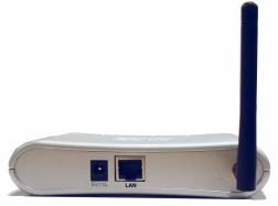
HARDWARE DESCRIPTION
The Wireless AP provides up to 108 Mbps connections to Ethernet networks. This device is fully compliant with 2.4 GHz DSSS/OFDM wireless networking as defined in IEEE 802.11b/g. The Wireless AP is backward compatible with the existing 802.11b WLAN infrastructure. It also can be connected via an RJ-45 connection to devices such as Nintendo GameCube, Microsoft Xbox, Sony PlayStation II, and Ethernet ready embedded devices. It functions as an IEEE 802.11g Access Point or as a Repeater (see “Introduction” on page 1).
Figure 1. |
Rear Panel |
|
|
|
|
Item |
|
Description |
|
|
|
Power Inlet |
|
Connect the included power adapter to this inlet. |
|
|
Warning: Using the wrong type of power adapter may damage |
|
|
your adapter. |
|
|
|
LAN Port |
|
Fast Ethernet port (RJ-45). Connect device (such as a PC, hub |
|
|
or switch) on your network to this port. |
|
|
|
Note: If you use the Reset button at the bottom of the device, the Wireless AP performs a power reset. If the button is depressed for over 8 seconds, all the LEDs will illuminate and the factory settings will be restored.
3
HARDWARE DESCRIPTION
Applications
EZ Connect wireless products offer a fast, reliable, cost-effective solution for wireless Ethernet client access to the network in applications such as:
•Video Game Systems
Provides wireless Internet access for users of video game systems such as Nintendo GameCube, Microsoft Xbox and Sony PlayStation II
•Remote access to corporate network information
Email, file transfer, and terminal emulation
•Difficult-to-wire environments
Historical or old buildings, asbestos installations, and open areas where wiring is difficult to employ
•Frequently changing environments
Retailers, manufacturers, and banks which frequently rearrange the workplace or change locations
•Temporary LANs for special projects or peak periods
Trade shows, exhibitions, and construction sites that need a temporary setup. Retailers, airline, and shipping companies that need additional workstations for peak periods. Auditors who require workgroups at customer sites
•Access to databases for mobile workers
Doctors, nurses, retailers, or white-collar workers who need access to databases while being mobile in a hospital, retail store, in an office, or on a campus
•SOHO users
SOHO (Small Office and Home Office) users who need easy and quick installation of a small computer network
4
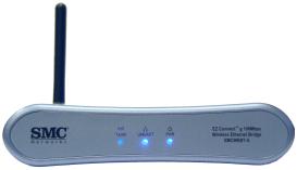
LED INDICATORS
LED Indicators
The Wireless AP includes three status LED indicators, as described in the following figure and table.
Figure 2. Front Panel
LED |
Status |
Description |
|
|
|
TX/RX |
On (Blue) |
The device has established a valid wireless |
(wireless) |
|
link. |
|
|
|
|
Flashing (Blue) |
The device is transmitting or receiving data |
|
|
via wireless. |
|
|
|
LINK/ACT |
On (Blue) |
The device has established a valid |
(WAN) |
|
100 Mbps Ethernet link. |
|
|
|
|
Flashing |
The device is transmitting or receiving data |
|
|
on the Ethernet LAN. |
|
|
|
PWR (power) |
On (Blue) |
Power is being supplied. |
|
|
|
5
HARDWARE DESCRIPTION
System Requirements
Before you install the Wireless AP, be sure you have met the following requirements:
•An AC power outlet (100~240 V, 50~60 Hz)
•An available RJ-45 (UTP) port on an Ethernet hub or switch
•802.11b/g compliant wireless Ethernet adapters with TCP/IP protocols installed
•TCP/IP network protocol installed on each PC that needs to access the Internet
•A web browser, such as Microsoft Internet Explorer 5.5 or above installed on one PC at your site for configuring the Wireless AP
6
HARDWARE INSTALLATION
1.Select the site – Choose a location for your Wireless AP. Usually, the best location is at the center of your wireless coverage area, if possible within line-of-sight of all wireless devices.
2.Place the Wireless AP in a position that gives it maximum coverage. Normally, the higher you place the antenna, the better the performance.
3.If used in Client Bridge mode, connect the Ethernet cable to the RJ-45 socket of the device that will communicate over a wireless connection with an access point.
4.If used in Access Point mode, connect the SMCWEBT-G to an Ethernet network device such as a hub or a switch using category 3, 4, or 5 UTP Ethernet cable and an RJ-45 connector.
5.Connect the power adapter cable to the 5 VDC power socket on the rear panel.
Warning: Use only the power adapter supplied with the SMCWEBT-G.
7
SYSTEM CONFIGURATION
The SMCWEBT-G is a Plug-and-Play device. This means that, in most cases, you will not need to configure it.
The latest firmware version may be downloaded from the SMC web site specified on the back cover of this manual.
The SMCWEBT-G can be configured by a web browser, specifically Internet Explorer 5.5 or above. Using the web management interface, you can configure the Wireless AP and view statistics to monitor network activity.
Before you attempt to log into the SMCWEBT-G’s web-based administration, please verify the following.
1.Your browser is configured properly (see below).
2.Disable any firewall or security software that may be running.
3.Confirm that you have a good link LED where your computer is plugged into the Wireless AP. If you don’t have a link light – then try another cable to get a good link.
4.To access the Internet through the Wireless AP, you must configure the network settings of the computers on your LAN to use the same IP subnet as the Wireless AP. The default network settings for the Wireless AP are:
SMCWEBT-G IP Address: 192.168.2.25
Subnet Mask: 255.255.255.0
8
Loading...