


 Loading...
MANAGEMENT
GUIDE
IEEE 802.11a/b/g/n
Enterprise Access Point
WAP5110

Enterprise Access Point
Management Guide
No. 1, Creation Road III, |
|
Hsinchu Science Park, |
March 2013 |
30077, Taiwan, R.O.C. |
|
TEL: +886 3 5638888 |
Pub. # 149100000223A |
Fax: +886 3 6686111 |
E032012-CS-R01 |
Information furnished by SMC Networks, Inc. (SMC) is believed to be accurate and reliable. However, no responsibility is assumed by SMC for its use, nor for any infringements of patents or other rights of third parties which may result from its use. No license is granted by implication or otherwise under any patent or patent rights of SMC. SMC reserves the right to change specifications at any time without notice.
Copyright © 2013 by
SMC Networks, Inc.
No. 1 Creation Road III,
Hsinchu Science Park,
30077, Taiwan, R.O.C.
All rights reserved
Trademarks:
SMC is a registered trademark; and EliteConnect, EZ Switch, TigerStack, TigerSwitch, and TigerAccess are trademarks of SMC Networks, Inc. Other product and company names are trademarks or registered trademarks of their respective holders.

Warranty and Product
Registration
To register SMC products and to review the detailed warranty statement, please refer to the Support Section of the SMC Website at http://www.smc.com.
– 4 –

How to Use This Guide
Who Should Read This
Guide?
How This Guide is Organized
Related
Documentation
This guide includes detailed information on the access point (AP) software, including how to operate and use the management functions of the AP. To deploy this AP effectively and ensure trouble-free operation, you should first read the relevant sections in this guide so that you are familiar with all its software features.
This guide is for network administrators who are responsible for operating and maintaining network equipment. The guide assumes a basic working knowledge of LANs (Local Area Networks), the Internet Protocol (IP), and Simple Network Management Protocol (SNMP).
The organization of this guide is based on the AP’s main management interfaces. The web management interface and command line interface (CLI) are described in separate sections. An introduction and initial configuration information is also provided.
The guide includes these sections:
Section I “Getting Started” — Includes an introduction to AP management and initial configuration settings.
Section II “Web Configuration” — Includes all management options available through the web interface.
Section III “Command Line Interface” — Includes information on how to use the CLI and details on all CLI commands.
Section IV “Appendices” — Includes information on troubleshooting AP management access.
This guide focuses on AP software configuration, it does not cover hardware installation of the AP. For specific information on how to install the AP, see the following guide:
Installation Guide
For all safety information and regulatory statements, see the following documents:
Quick Start Guide
Safety and Regulatory Information
– 5 –
How to Use This Guide
Conventions The following conventions are used throughout this guide to show information:
Note: Emphasizes important information or calls your attention to related features or instructions.
Caution: Alerts you to a potential hazard that could cause loss of data, or damage the system or equipment.
Warning: Alerts you to a potential hazard that could cause personal injury.
Revision History This section summarizes the changes in each revision of this guide.
March 2013 Revision
This is the first revision of this guide. It is valid for software release v0.3.3.8.
– 6 –

Contents
Warranty and Product Registration |
4 |
How to Use This Guide |
5 |
Contents |
7 |
Figures |
12 |
Tables |
14 |
Section I |
Getting Started |
17 |
1 |
Introduction |
18 |
|
Configuration Options |
18 |
|
Console Port Connection |
19 |
|
Console Login |
19 |
|
Network Connections |
20 |
|
Connecting to the Web Interface |
20 |
|
Home Page and Main Menu |
21 |
|
Common Web Page Buttons |
22 |
2 |
Initial Configuration |
24 |
|
CLI Initial Configuration Steps |
24 |
|
Setting an IP Address |
24 |
|
Setting a Password |
25 |
|
Setting the Country Code |
25 |
|
Web Quick Start |
26 |
|
Step 1 |
26 |
|
Step 2 |
28 |
|
Step 3 |
29 |
|
Step 4 |
31 |
– 7 –

Contents
Section II |
Web Configuration |
32 |
3 |
System Settings |
33 |
|
Administration Settings |
34 |
|
IPv4 Address |
35 |
|
IPv6 Address |
36 |
|
RADIUS Settings |
37 |
|
Primary and Secondary RADIUS Server Setup |
37 |
|
RADIUS Accounting |
38 |
|
System Time |
39 |
|
SNTP Server Settings |
40 |
|
Time Zone Setting |
40 |
|
Daylight Saving Settings |
40 |
|
VLAN Configuration |
40 |
|
System Logs |
42 |
|
Quick Start Wizard |
43 |
|
System Resource |
44 |
|
Bridge STP Configuration |
45 |
|
Spanning Tree Protocol (STP) |
45 |
|
Bridge Configuration |
48 |
4 |
Management Settings |
49 |
|
Remote Management Settings |
49 |
|
Access Limitation |
51 |
|
Simple Network Management Protocol |
52 |
|
SNMP Basic Settings |
52 |
|
SNMP Trap Settings |
54 |
|
View Access Control Model |
55 |
|
SNMPv3 Users |
56 |
|
SNMPv3 Targets |
57 |
|
SNMPv3 Notification Filters |
58 |
5 |
Advanced Settings |
60 |
|
Local Bridge Filter |
60 |
– 8 –

Contents
|
Link Layer Discovery Protocol |
61 |
|
Access Control Lists |
63 |
|
Source Address Settings |
63 |
|
Destination Address Settings |
64 |
|
Ethernet Type |
65 |
|
Link Integrity |
66 |
6 |
Wireless Settings |
67 |
|
Authentication |
68 |
|
Local MAC Authentication |
68 |
|
RADIUS MAC Authentication |
69 |
|
Band Steering |
70 |
|
Radio Settings |
71 |
|
Virtual Access Points (VAPs) |
75 |
|
VAP Basic Settings |
76 |
|
WDS-STA Mode |
78 |
|
Wireless Security Settings |
79 |
|
Wired Equivalent Privacy (WEP) |
81 |
|
VAP QoS Settings |
82 |
|
VAP Bandwidth Settings |
84 |
|
Rogue AP Detection |
84 |
|
Wi-Fi Multimedia (WMM) |
86 |
7 |
Maintenance Settings |
91 |
|
Upgrading Firmware |
91 |
|
Running Configuration |
93 |
|
Resetting the Access Point |
94 |
|
Scheduled Reboot |
95 |
8 |
Status Information |
97 |
|
AP Status |
98 |
|
AP System Configuration |
98 |
|
AP Wireless Configuration |
100 |
|
Station Status |
101 |
|
Station Statistics |
102 |
|
Event Logs |
103 |
– 9 –

Contents
WDS Status |
104 |
Section III |
Command Line Interface |
107 |
9 |
Using the Command Line Interface |
109 |
|
Console Connection |
109 |
|
Telnet Connection |
110 |
|
Entering Commands |
111 |
|
Keywords and Arguments |
111 |
|
Minimum Abbreviation |
111 |
|
Command Completion |
111 |
|
Getting Help on Commands |
111 |
|
Showing Commands |
111 |
|
Negating the Effect of Commands |
112 |
|
Using Command History |
112 |
|
Understanding Command Modes |
112 |
|
Command Line Processing |
114 |
10 |
General Commands |
115 |
11 |
System Management Commands |
119 |
12 |
System Logging Commands |
139 |
13 |
System Clock Commands |
144 |
14 |
DHCP Relay Commands |
149 |
15 |
SNMP Commands |
151 |
16 |
Flash/File Commands |
164 |
17 |
RADIUS Client Commands |
167 |
18 |
802.1X Authentication Commands |
173 |
19 |
MAC Address Authentication Commands |
175 |
20 |
Filtering Commands |
179 |
– 10 –
Contents
21 |
Spanning Tree Commands |
185 |
22 |
WDS Bridge Commands |
197 |
23 |
Ethernet Interface Commands |
199 |
24 |
Wireless Interface Commands |
206 |
25 |
Wireless Security Commands |
234 |
26 |
Rogue AP Detection Commands |
243 |
27 |
Link Integrity Commands |
249 |
28 |
Link Layer Discovery Commands |
252 |
29 |
VLAN Commands |
256 |
30 |
WMM Commands |
260 |
31 |
QoS Commands |
265 |
Section IV |
Appendices |
273 |
A |
Troubleshooting |
274 |
|
Problems Accessing the Management Interface |
274 |
|
Using System Logs |
274 |
|
Index of CLI Commands |
276 |
|
Index |
278 |
– 11 –

Figures
Figure 1: |
Login Page |
21 |
Figure 2: |
The Home Page |
21 |
Figure 3: |
Set Configuration Changes |
22 |
Figure 4: |
Help Menu |
23 |
Figure 5: |
Quick Start - Step 1 |
27 |
Figure 6: |
Quick Start - Step 2 |
28 |
Figure 7: |
Quick Start - Step 3 |
29 |
Figure 8: |
Quick Start - Step 4 |
31 |
Figure 9: |
Administration |
34 |
Figure 10: |
IPv4 Configuration |
35 |
Figure 11: |
IPv6 Configuration |
36 |
Figure 12: |
RADIUS Settings |
38 |
Figure 13: |
SNTP Settings |
39 |
Figure 14: |
Setting the VLAN Identity |
41 |
Figure 15: |
System Log Settings |
42 |
Figure 16: |
System Resource |
44 |
Figure 17: |
Spanning Tree Protocol |
46 |
Figure 18: |
Bridge Configuration |
48 |
Figure 19: |
Remote Management |
50 |
Figure 20: |
Access Limitation |
51 |
Figure 21: |
SNMP Basic Settings |
53 |
Figure 22: |
SNMP Trap Settings |
54 |
Figure 23: |
SNMP VACM |
55 |
Figure 24: |
Configuring SNMPv3 Users |
56 |
Figure 25: |
SNMPv3 Targets |
58 |
Figure 26: |
SNMP Notification Filter |
58 |
Figure 27: |
Local Bridge Filter |
60 |
Figure 28: |
LLDP Settings |
61 |
Figure 29: |
Source ACLs |
63 |
– 12 –

Figures
Figure 30: |
Destination ACLs |
64 |
Figure 31: Ethernet Type Filter |
65 |
|
Figure 32: |
Link Integrity |
66 |
Figure 33: |
Local Authentication |
68 |
Figure 34: |
RADIUS Authentication |
69 |
Figure 35: |
Band Steering |
70 |
Figure 36: |
Radio Settings |
71 |
Figure 37: |
VAP Settings |
76 |
Figure 38: VAP Basic Settings |
77 |
|
Figure 39: |
WDS-STA Mode |
78 |
Figure 40: Configuring VAPs - Security Settings |
79 |
|
Figure 41: |
WEP Configuration |
81 |
Figure 42: |
QoS Settings |
82 |
Figure 43: QoS Template Setting |
83 |
|
Figure 44: |
Bandwidth Settings |
84 |
Figure 45: Rogue AP Detection |
85 |
|
Figure 46: WMM Backoff Wait Times |
88 |
|
Figure 47: |
QoS |
88 |
Figure 48: |
Firmware |
92 |
Figure 49: Running Configuration File |
93 |
|
Figure 50: Resetting the Access Point |
95 |
|
Figure 51: Reboot Schedule — Fixed Time |
95 |
|
Figure 52: Reboot Schedule — Countdown Time |
96 |
|
Figure 53: AP System Configuration |
98 |
|
Figure 54: AP Wireless Configuration |
100 |
|
Figure 55: |
Station Status |
101 |
Figure 56: |
Station Statistics |
102 |
Figure 57: |
Event Logs |
103 |
Figure 58: |
WDS Status |
104 |
– 13 –

Tables
Table 1: |
Logging Levels |
43 |
Table 2: |
WMM Access Categories |
87 |
Table 3: |
Command Modes |
113 |
Table 4: |
General Commands |
115 |
Table 5: |
System Management Commands |
119 |
Table 6: |
Country Codes |
120 |
Table 7: |
System Management Commands |
139 |
Table 8: |
Logging Levels |
141 |
Table 9: |
System Clock Commands |
144 |
Table 10: |
DHCP Relay Commands |
149 |
Table 11: |
SNMP Commands |
151 |
Table 12: |
Flash/File Commands |
164 |
Table 13: |
RADIUS Client Commands |
167 |
Table 14: |
802.1x Authentication |
173 |
Table 15: |
MAC Address Authentication |
175 |
Table 16: |
Filtering Commands |
179 |
Table 17: |
Spanning Tree Commands |
185 |
Table 18: |
WDS Bridge Commands |
197 |
Table 19: |
Ethernet Interface Commands |
199 |
Table 20: |
Wireless Interface Commands |
206 |
Table 21: |
Wireless Security Commands |
234 |
Table 22: |
Rogue AP Detection Commands |
243 |
Table 23: |
Link Integrity Commands |
249 |
Table 24: |
Link Layer Discovery Commands |
252 |
Table 25: |
VLAN Commands |
256 |
Table 26: |
WMM Commands |
260 |
Table 27: |
AP Parameters |
262 |
Table 28: |
BSS Parameters |
263 |
Table 29: |
QoS Commands |
265 |
– 14 –

Tables
Table 30: Troubleshooting Chart |
274 |
– 15 –

Tables
– 16 –

Section I
Getting Started
This section provides an overview of the access point, and introduces some basic concepts about wireless networking. It also describes the basic settings required to access the management interface.
This section includes these chapters:
“Introduction” on page 18
“Initial Configuration” on page 24
– 17 –

1 Introduction
The access point (AP) runs software that includes a network management agent. The agent offers a variety of management options, including SNMP and a webbased interface. A PC may also be connected directly to the AP’s console port for configuration using a command line interface (CLI).
Configuration Options
The AP’s HTTP web agent allows you to configure AP parameters, monitor wireless connections, and display statistics using a standard web browser such as Internet Explorer 6.x or above, and Mozilla Firefox 3.6.2/4/5. The AP’s web management interface can be accessed from any computer attached to the network.
The CLI program can be accessed by a direct connection to the RS-232 serial console port on the AP, or remotely by a Telnet or Secure Shell (SSH) connection over the network.
The AP’s management agent also supports SNMP (Simple Network Management Protocol). This SNMP agent permits the AP to be managed from any computer in the network using network management software.
The AP’s web interface, console interface, and SNMP agent allow you to perform management functions such as:
Set management access user names and passwords
Configure IP settings
Configure SNMP parameters
Configure 2.4 GHz and 5 GHz radio settings
Control access through wireless security settings
Filter packets using Access Control Lists (ACLs)
Upload and download system firmware or configuration files
Display system information and statistics
– 18 –

Chapter 1 | Introduction
Console Port Connection
Console Port Connection
The AP provides an RS-232 serial console port that enables a connection to a PC or terminal for monitoring and configuring the AP. A null-modem console cable is provided with the AP.
Attach a VT100-compatible terminal, or a PC running a terminal emulation program to the AP. You can use the console cable provided with this package, or use a nullmodem cable that complies with the wiring assignments shown in the Installation Guide.
To connect a terminal to the console port, complete the following steps:
1.Connect the console cable to the serial port on a terminal, or a PC running terminal emulation software, and tighten the captive retaining screws on the DB-9 connector.
2.Connect the other end of the cable to the console port on the AP.
3.Make sure the terminal emulation software is set as follows:
■Select the appropriate serial port (COM port 1 or COM port 2).
■Set the baud rate to 115200 bps.
■Set the data format to 8 data bits, 1 stop bit, and no parity.
■Set flow control to none.
■Set the emulation mode to VT100.
■When using HyperTerminal, select Terminal keys, not Windows keys.
Note: Once you have set up the terminal correctly, the console login screen will be displayed.
For a description of how to use the CLI, see “Using the Command Line Interface” on page 109. For a list of all the CLI commands, refer to “Index of CLI Commands” on page 276.
Console Login Access to the CLI is controlled by user names and passwords. The AP has a default user name and password. To log into the CLI using the default user name and password, perform these steps:
1.To initiate your console connection, press <Enter>. The “User Access Verification” procedure starts.
– 19 –

Chapter 1 | Introduction
Network Connections
2.At the login prompt, enter “admin.”
3.At the Password prompt, press <Enter>. There is no default password.
4.The session is opened and the CLI displays the “SMC#” prompt indicating you have access to the CLI commands.
Example
(none) login: admin Password:
Jan 1 11:33:13 login[1918]: root login on 'ttyS0'
SMC#
Network Connections
Prior to accessing the AP’s management agent through a network connection, you must first configure it with a valid IP address, subnet mask, and default gateway using a console connection, or the DHCP protocol.
The AP has a static default management IPv4 address of 192.168.1.10 and a subnet mask of 255.255.255.0.
Once the AP’s IP settings are configured for the network, you can access the AP’s management agent from anywhere within the attached network. The management agent can be accessed using Telnet from any computer attached to the network. The AP can also be managed by any computer using a web browser, or from a network computer using SNMP network management software.
Connecting to the Web Interface
The AP offers a user-friendly web-based management interface for the configuration of all the unit’s features. Any PC directly attached to the unit can access the management interface using a web browser, such as Internet Explorer (version 6.x or above) or Firefox (version 2.x or above).
You may want to make initial configuration changes by connecting a PC directly to the AP’s LAN port. The AP has a default management IP address of 192.168.1.10 and a subnet mask of 255.255.255.0. You must set your PC IP address to be on the same subnet as the AP (that is, the PC and AP addresses must both start 192.168.1.x).
To access the AP’s web management interface, follow these steps:
1.Use your web browser to connect to the management interface using the default IP address of 192.168.1.10.
– 20 –

Chapter 1 | Introduction
Connecting to the Web Interface
2.Log into the interface by entering the default username “admin” with no password, then click Login.
Note: It is strongly recommended to change the default user name and password the first time you access the web interface. For information on changing user names and passwords, See “Administration Settings” on page 34.
Figure 1: Login Page
Home Page and Main
Menu
After logging in to the web interface, the home page displays. The home page shows some basic settings for the AP, including Country Code and the management access password.
Figure 2: The Home Page
The web interface Main Menu menu provides access to all the configuration settings available for the AP.
– 21 –

Chapter 1 | Introduction Connecting to the Web Interface
Common Web Page
Buttons
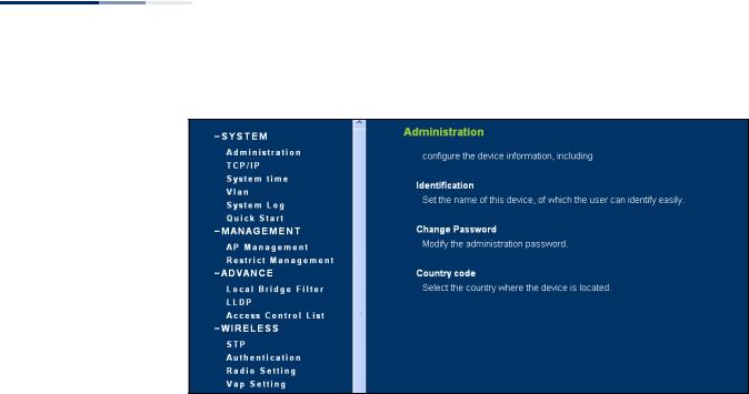
To configure settings, click the relevant Main Menu item. Each Main Menu item is sumarized below with links to the relevant section in this guide where configuration parameters are described in detail:
System — Configures Management IP, WAN, LAN and QoS settings. See “System Settings” on page 33.
Administration — Configures HTTP, Telnet, and SSH access settings. See “Management Settings” on page 49.
Advanced — Confiures LLDP and Access Control Lists. See “Advanced Settings” on page 60.
Wireless — Configures AP radio settings. See “Wireless Settings” on page 67.
SNMP — Configures SNMP settings. See “Management Settings” on page 49.
Maintentance — Enables firmware upgrades and resets the AP. See “Maintenance Settings” on page 91.
Information — Displays current system settings. See “Status Information” on page 97.
The list below describes the common buttons found on most web management pages:
Set – Applies the new parameters and saves them to temporary RAM memory. Also displays a screen to inform you when it has taken affect. Clicking ‘OK’ returns to the home page. The running configuration will not be saved upon a reboot unless you use the “Save Config” button.
Figure 3: Set Configuration Changes
Cancel – Cancels the newly entered settings and restores the originals.
Help – Displays the help window.
– 22 –
Chapter 1 | Introduction
Connecting to the Web Interface
Figure 4: Help Menu
Logout – Ends the web management session.
Save Config – Saves the current configuration so that it is retained after a restart.
– 23 –

2 |
Initial Configuration |
The AP’s initial configuration steps can be made through the CLI or web browser interface. If the AP is not configured with an IP address that is compatible with your network. You can first use the command line interface (CLI) as described below to configure a valid IP address.
CLI Initial Configuration Steps
First connect to the AP’s console port and log in to the CLI, as described in “Console
Port Connection” on page 19. Then proceed with the required configuration.
Setting an IP Address If the default IP address is not compatible with your network or a DHCP server is not available, the AP’s IP address must be configured manually using the CLI.
Type “configure” to enter configuration mode, then type “interface ethernet” to access the Ethernet interface-configuration mode.
SMC#configure
SMC(config)#interface ethernet
SMC(config-if)#
First type “no ip dhcp” to disable DHCP client mode. Then type “ip address ipaddress netmask gateway,” where “ip-address” is the access point’s IP address, “netmask” is the network mask for the network, and “gateway” is the default gateway router. Check with your system administrator to obtain an IP address that is compatible with your network.
SMC(if-ethernet)#no ip dhcp
SMC(if-ethernet)#ip address 192.168.2.2 255.255.255.0 192.168.2.254
SMC(if-ethernet)#
After configuring the access point’s IP parameters, you can access the management interface from anywhere within the attached network. The command line interface can also be accessed using Telnet from any computer attached to the network.
Note: Command examples shown later in this manual abbreviate the console prompt to “AP” for simplicity.
– 24 –
Chapter 2 | Initial Configuration
CLI Initial Configuration Steps
Setting a Password If you are logging in to the CLI for the fist time, you should define management access passwords for an administrator and guest (used for CLI and web management), record them, and then keep them in a safe place.
Note: If you loose your management access passwords, you will need to use the
Reset button on the AP to set the configuration back to factory default values.
Passwords can consist of 5 to 32 alphanumeric characters and are case sensitive. To prevent unauthorized access to the AP, set the passwords as follows:
Open the console interface to access the CLI prompt. Type “configure” and press <Enter>. Type “password admin null password,” where “null” is the default old password, and “password” is your new password. Press <Enter>.
Example
AP#configure
AP(config)#password admin null tpschris
AP(config)#
Setting the Country
Code
You must set the country code of the AP to be sure that the radios operate according to permitted local regulations. That is, setting the country code restricts operation of the AP to the radio channels and transmit power levels permitted for wireless networks in the specified country.
Caution: You must set the country code to the country of operation. Setting the country code ensures that the radios operate within the local regulations specified for wireless networks.
Note: The country code selection is for non-US models only and is not available to all US models. Per FCC regulation, all Wi-Fi products marketed in the US must be fixed to US operation channels only.
From the CLI prompt, type “country ?” to display the list of country codes. Select the code for your country, and enter the command again, following by your country code (for example., “tw” for Taiwan).
Example
AP#country ?
WORD Country code:
AL-ALBANIA, DZ-ALGERIA, AR-ARGENTINA, AM-ARMENIA, AU-AUSTRALIA, AT-AUSTRIA, AZ-AZERBAIJAN,
BH-BAHRAIN, BY-BELARUS, BE-BELGIUM, BZ-BELIZE, BO-BOLIVIA,
– 25 –

Chapter 2 | Initial Configuration
Web Quick Start
BA-BOSNIA, BR-BRAZIL, BN-BRUNEI_DARUSSALAM, BG-BULGARIA,
CA-CANADA, CL-CHILE, CN-CHINA, CO-COLOMBIA, CR-COSTA_RICA,
HR-CROATIA, CY-CYPRUS, CZ-CZECH_REPUBLIC, DK-DENMARK,
DK-DENMARK, DO-DOMINICAN_REPUBLIC,
EC-ECUADOR, EG-EGYPT, EE-ESTONIA,
FI-FINLAND, FO-FAROE_ISLANDS, FR-FRANCE, F2-FRANCE2,
GE-GEORGIA, DE-GERMANY, GR-GREECE, GT-GUATEMALA,
HK-HONG_KONG, HN-HONDURAS, HU-HUNGARY,
IS-ICELAND, IN-INDIA, ID-INDONESIA, IR-IRAN, IQ-IRAQ, IE-IRELAND,
IL-ISRAEL, IT-ITALY,
JM-JAMAICA, JP0-JAPAN0, JP3-JAPAN3(including 4.9G channels), JO-JORDAN,
KE-KENYA, KZ-KAZAKHSTAN, KP-NORTH KOREA, KR-KOREA_REPUBLIC,
K2-KOREA_REPUBLIC2(including 2.3G channels),
K3-KOREA_REPUBLIC3(more channels in 5G), KW-KUWAIT,
LV-LATVIA, LB-LEBANON, LI-LIECHTENSTEIN, LT-LITHUANIA,
LU-LUXEMBOURG, LY-LIBYA, MO-MACAU,
MO-MACAU, MK-MACEDONIA, MY-MALAYSIA, MT-MALTA, MX-MEXICO,
MC-MONACO, MA-MOROCCO,
NL-NETHERLANDS, AN-NETHERLANDS-ANTELLIS, NZ-NEW_ZEALAND,
NI-NICARGUA, NO-NORWAY,
OM-OMAN,
PK-PAKISTAN, PA-PANAMA, PY-PARAGUAY, PE-PERU, PH-PHILIPPINES,
PL-POLAND, PT-PORTUGAL, PR-PUERTO_RICO,
QA-QATAR,
RO-ROMANIA, RU-RUSSIA,
SA-SAUDI_ARABIA, RS_ME-SERBIA & MONTENEGRO, SG-SINGAPORE, SI-SLOVENIA,
SK-SLOVAK_REPUBLIC, SV-EL SALVADOR, ZA-SOUTH_AFRICA, ES-SPAIN,
LK-SRILANKA, SE-SWEDEN, CH-SWITZERLAND, SY-SYRIA,
TW-TAIWAN, TH-THAILAND, TT-TRINIDAD & TOBAGO, TN-TUNISIA, TR-TURKEY,
AE-UNITED_ARAB_EMIRATES, GB-UNITED_KINGDOM, UA-UKRAINE,
US-UNITED_STATES, PS-UNITED_STATES(PUBLIC SAFETY), UY-URUGUAY,
UZ-UZBEKISTAN,
VE-VENEZUELA, VN-VIETNAM, YE-YEMEN,
ZW-ZIMBABWE
AP# country tw
AP#
Web Quick Start
The web interface Quick Start menu is designed to help you configure the basic settings required to get the AP up and running.
Click “System’” followed by “Quick Start’”
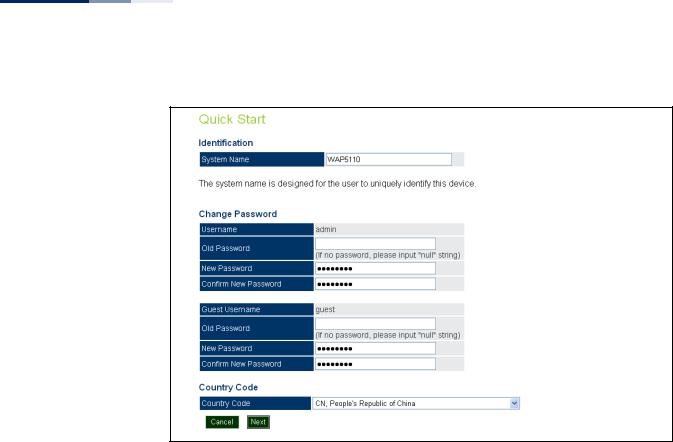
Step 1 The first page of the Quick Start configures the system identification, access password, and the Country Code.
– 26 –
Chapter 2 | Initial Configuration
Web Quick Start
Figure 5: Quick Start - Step 1
The following items are displayed on the first page of the Quick Start wizard:
Identification
System Name — The name assigned to the access point. (Default: WAP5110)
Change Password
Username/Guest Username — The name of the user is fixed as either “admin” or “guest” and is not configurable.
Old Password — If the unit has been configured with a password already, enter that password, otherwise enter the default password “null.”
New Password — The password for management access. (Length: 5-32 characters, case sensitive)
Confirm New Password — Enter the password again for verification.
Country Code
Country Code — Configures the access point’s country code from a drop down menu, which identifies the country of operation and sets the authorized radio channels.
– 27 –
Chapter 2 | Initial Configuration
Web Quick Start
Caution: You must set the country code to the country of operation. Setting the country code restricts operation of the access point to the radio channels and transmit power levels permitted for wireless networks in the specified country.
Cancel — Cancels the newly entered settings and restores the orignals.
Next — Proceeds to the next page.
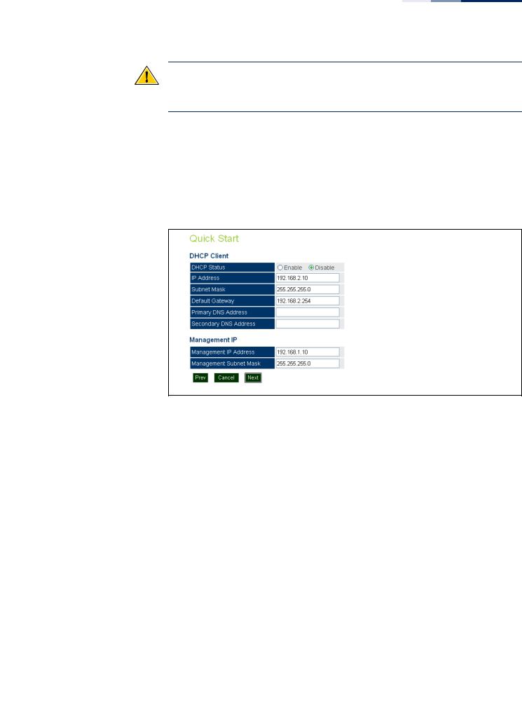
Step 2 The second page of the Quick Start configures IP settings and DHCP client status.
Figure 6: Quick Start - Step 2
The following items are displayed on this page:
DHCP
DHCP Status — Enables/disables DHCP on the access point. (Default: Disabled)
IP Address — Specifies an IP address for the access point. Valid IP addresses consist of four decimal numbers, 0 to 255, separated by periods. (Default: 192.168.2.10.)
Subnet Mask — Indicates the local subnet mask. Select the desired mask from the drop down menu. (Default: 255.255.255.0)
Default Gateway — The default gateway is the IP address of the router for the access point, which is used if the requested destination address is not on the local subnet. (Default: 192.168.2.254)
If you have DNS, RADIUS, or other network servers located on another subnet, type the IP address of the default gateway router in the text field provided.
–28 –
Chapter 2 | Initial Configuration
Web Quick Start
Primary and Secondary DNS Address — The IP address of Domain Name Servers on the network. A DNS maps numerical IP addresses to domain names and can be used to identify network hosts by familiar names instead of the IP addresses. (The default Primary and Secondary DNS addresses are null values.)
Management IP — The IPv4 address of the AP through which you can access management interfaces.
■
■
Management IP Address — Specifies an IPv4 address for management of the access point. (Default: 192.168.1.10.)
Management Subnet Mask — Indicates the local subnet mask. (Default: 255.255.255.0)
Prev — Returns to the previous screen.
Cancel — Cancels the newly entered settings and restores the orignals.
Next — Proceeds to the final step in the Quick Start wizard.
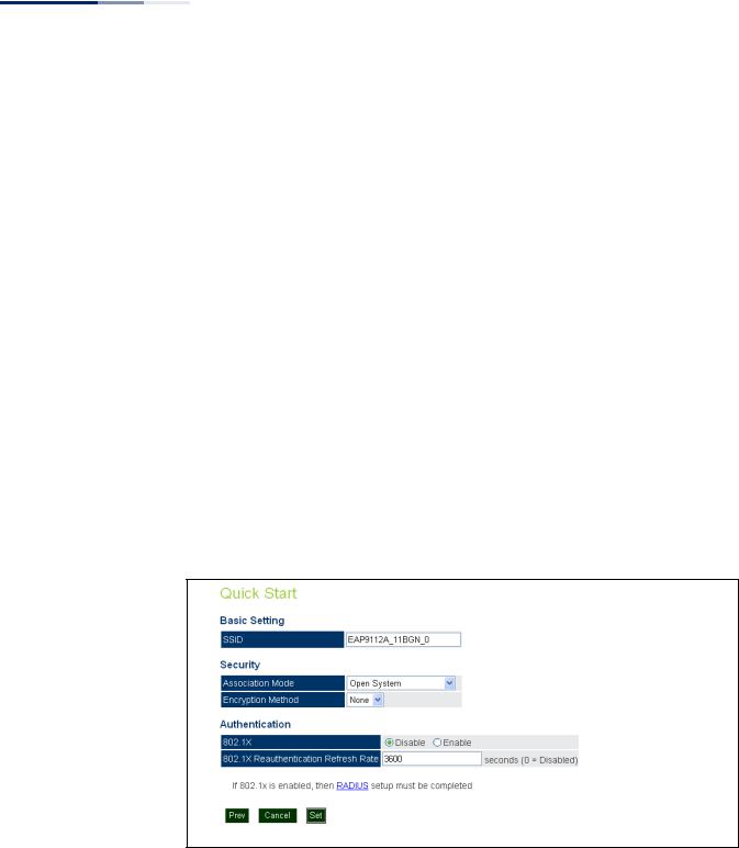
Step 3 The Step 3 page of the Quick Start configures basic radio and wireless security settings.
Figure 7: Quick Start - Step 3
The following items are displayed on this page:
Basic Setting
SSID — The name of the basic service set provided by the primary VAP interface. Clients that want to connect to the network through the AP must set their SSID to the same as that of a VAP interface.
(Default: EAP9112A_11BGN_0; Range: 1-32 characters)
– 29 –

Chapter 2 | Initial Configuration
Web Quick Start
Security
Association Mode — Defines the mode with which the VAP will associate with clients. (For more information on security modes, see “Wireless Security Settings” on page 79.)
■Open System: The VAP is configured by default as an “open system,” which broadcasts a beacon signal including the configured SSID. Wireless clients with an SSID setting of “any” can read the SSID from the beacon and automatically set their SSID to allow immediate connection.
■WPA: WPA employs a combination of several technologies to provide an enhanced security solution for 802.11 wireless networks.
■WPA-PSK: For enterprise deployment, WPA requires a RADIUS authentication server to be configured on the wired network. However, for small office networks that may not have the resources to configure and maintain a RADIUS server, WPA provides a simple operating mode that uses just a pre-shared password for network access. The Pre-Shared Key mode uses a common password for user authentication that is manually entered on the access point and all wireless clients. The PSK mode uses the same TKIP packet encryption and key management as WPA in the enterprise, providing a robust and manageable alternative for small networks.
■WPA2: WPA was introduced as an interim solution for the vulnerability of WEP pending the ratification of the IEEE 802.11i wireless security standard. In effect, the WPA security features are a subset of the 802.11i standard. WPA2 includes the now ratified 802.11i standard, but also offers backward compatibility with WPA. Therefore, WPA2 includes the same 802.1X and PSK modes of operation and support for TKIP encryption.
■WPA2-PSK: Clients using WPA2 with a Pre-shared Key are accepted for authentication.
■WPA-WPA2 Mixed: Clients using WPA or WPA2 are accepted for authentication.
■WPA-WPA2-PSK-mixed: Clients using WPA or WPA2 with a Pre-shared Key are accepted for authentication.
Encryption Method — Selects an encryption method for the global key used for multicast and broadcast traffic, which is supported by all wireless clients.
■WEP: WEP is used as the multicast encryption cipher. You should select WEP only when both WPA and WEP clients are supported.
■TKIP: TKIP is used as the multicast encryption cipher.
■AES-CCMP: AES-CCMP is used as the multicast encryption cipher. AESCCMP is the standard encryption cipher required for WPA2.
–30 –
Loading...