


 Loading...
 TigerSwitch 1000
Gigabit Ethernet Switch
6 1000BASE-SX ports
Two slots for hot-swappable 1000BASE-X GBIC modules
16 Gbps of aggregate switch bandwidth
Support for redundant power unit
Up to four port trunks per switch
Port mirroring for non-intrusive analysis
QoS support for two-level priority
Full support for IEEE 802.1Q VLANs
IGMP multicast filtering and snooping
Manageable via console, Web, SNMP/RMON
Installation Guide
SMC8606SX

TigerSwitch 1000
Installation Guide
From SMC’s Tiger line of feature-rich workgroup LAN solutions
6 Hughes |
|
Irvine, CA 92618 |
October 2001 |
Phone: (949) 707-2400 |
Pub. #150200001900A R01 |
Information furnished by SMC Networks, Inc. (SMC) is believed to be accurate and reliable. However, no responsibility is assumed by SMC for its use, nor for any infringements of patents or other rights of third parties which may result from its use. No license is granted by implication or otherwise under any patent or patent rights of SMC. SMC reserves the right to change specifications at any time without notice.
Copyright © 2001 by SMC Networks, Inc.
6 Hughes
Irvine, CA 92618
All rights reserved. Printed in Taiwan
Trademarks:
SMC is a registered trademark; and EZ Switch, TigerStack and TigerSwitch are trademarks of SMC Networks, Inc. Other product and company names are trademarks or registered trademarks of their respective holders.
LIMITED WARRANTY
Limited Warranty
Limited Warranty Statement: SMC Networks, Inc. (“SMC”) warrants its products to be free from defects in workmanship and materials, under normal use and service, for the applicable warranty term. All SMC products carry a standard 90-day limited warranty from the date of purchase from SMC or its Authorized Reseller. SMC may, at its own discretion, repair or replace any product not operating as warranted with a similar or functionally equivalent product, during the applicable warranty term. SMC will endeavor to repair or replace any product returned under warranty within 30 days of receipt of the product.
The standard limited warranty can be upgraded to a Limited Lifetime* warranty by registering new products within 30 days of purchase from SMC or its Authorized Reseller. Registration can be accomplished via the enclosed product registration card or online via the SMC web site. Failure to register will not affect the standard limited warranty. The Limited Lifetime warranty covers a product during the Life of that Product, which is defined as the period of time during which the product is an “Active” SMC product. A product is considered to be “Active” while it is listed on the current SMC price list. As new technologies emerge, older technologies become obsolete and SMC will, at its discretion, replace an older product in its product line with one that incorporates these newer technologies. At that point, the obsolete product is discontinued and is no longer an “Active” SMC product. A list of discontinued products with their respective dates of discontinuance can be found at http://www.smc.com/smc/pages_html/support.html.
All products that are replaced become the property of SMC. Replacement products may be either new or reconditioned. Any replaced or repaired product carries either a 30-day limited warranty or the remainder of the initial warranty, whichever is longer. SMC is not responsible for any custom software or firmware, configuration information, or memory data of Customer contained in, stored on, or integrated with any products returned to SMC pursuant to any warranty. Products returned to SMC should have any customer-installed accessory or add-on components, such as expansion modules, removed prior to returning the product for replacement. SMC is not responsible for these items if they are returned with the product.
Customers must contact SMC for a Return Material Authorization number prior to returning any product to SMC. Proof of purchase may be required. Any product returned to SMC without a valid Return Material Authorization (RMA) number clearly marked on the outside of the package will be returned to customers at customer’s expense. For warranty claims within North America, please call our toll-free customer support number at (800) 762-4968. Customers are responsible for all shipping charges from their facility to SMC. SMC is responsible for return shipping charges from SMC to customer.
WARRANTIES EXCLUSIVE: IF AN SMC PRODUCT DOES NOT OPERATE AS WARRANTED ABOVE, CUSTOMER’S SOLE REMEDY SHALL BE REPAIR OR REPLACEMENT OF THE PRODUCT IN QUESTION, AT SMC’S OPTION. THE FOREGOING WARRANTIES AND REMEDIES ARE EXCLUSIVE AND ARE IN LIEU OF ALL OTHER WARRANTIES OR CONDITIONS, EXPRESS OR IMPLIED, EITHER
LIMITED WARRANTY
IN FACT OR BY OPERATION OF LAW, STATUTORY OR OTHERWISE, INCLUDING WARRANTIES OR CONDITIONS OF MERCHANTABILITY AND FITNESS FOR A PARTICULAR PURPOSE. SMC NEITHER ASSUMES NOR AUTHORIZES ANY OTHER PERSON TO ASSUME FOR IT ANY OTHER LIABILITY IN CONNECTION WITH THE SALE, INSTALLATION, MAINTENANCE OR USE OF ITS PRODUCTS. SMC SHALL NOT BE LIABLE UNDER THIS WARRANTY IF ITS TESTING AND EXAMINATION DISCLOSE THE ALLEGED DEFECT IN THE PRODUCT DOES NOT EXIST OR WAS CAUSED BY CUSTOMER’S OR ANY THIRD PERSON’S MISUSE, NEGLECT, IMPROPER INSTALLATION OR TESTING, UNAUTHORIZED ATTEMPTS TO REPAIR, OR ANY OTHER CAUSE BEYOND THE RANGE OF THE INTENDED USE, OR BY ACCIDENT, FIRE, LIGHTNING, OR OTHER HAZARD.
LIMITATION OF LIABILITY: IN NO EVENT, WHETHER BASED IN CONTRACT OR TORT (INCLUDING NEGLIGENCE), SHALL SMC BE LIABLE FOR INCIDENTAL, CONSEQUENTIAL, INDIRECT, SPECIAL, OR PUNITIVE DAMAGES OF ANY KIND, OR FOR LOSS OF REVENUE, LOSS OF BUSINESS, OR OTHER FINANCIAL LOSS ARISING OUT OF OR IN CONNECTION WITH THE SALE, INSTALLATION, MAINTENANCE, USE, PERFORMANCE, FAILURE, OR INTERRUPTION OF ITS PRODUCTS, EVEN IF SMC OR ITS AUTHORIZED RESELLER HAS BEEN ADVISED OF THE POSSIBILITY OF SUCH DAMAGES.
SOME STATES DO NOT ALLOW THE EXCLUSION OF IMPLIED WARRANTIES OR THE LIMITATION OF INCIDENTAL OR CONSEQUENTIAL DAMAGES FOR CONSUMER PRODUCTS, SO THE ABOVE LIMITATIONS AND EXCLUSIONS MAY NOT APPLY TO YOU. THIS WARRANTY GIVES YOU SPECIFIC LEGAL RIGHTS, WHICH MAY VARY FROM STATE TO STATE. NOTHING IN THIS WARRANTY SHALL BE TAKEN TO AFFECT YOUR STATUTORY RIGHTS.
* SMC will provide warranty service for one year following discontinuance from the active SMC price list. Under the limited lifetime warranty, internal and external power supplies, fans, and cables are covered by a standard one-year warranty from date of purchase.
SMC Networks, Inc.
6 Hughes
Irvine, CA 92618

COMPLIANCES
FCC - Class A
This equipment generates, uses, and can radiate radio frequency energy and, if not installed and used in accordance with the instruction manual, may cause interference to radio communications. It has been tested and found to comply with the limits for a Class A computing device pursuant to Subpart B of Part 15 of FCC Rules, which are designed to provide reasonable protection against such interference when operated in a commercial environment. Operation of this equipment in a residential area is likely to cause interference, in which case the user, at his own expense, will be required to take whatever measures may be required to correct the interference. You are cautioned that changes or modifications not expressly approved by the party responsible for compliance could void your authority to operate the equipment.
You may use Category 5 or 5e UTP or STP cable for RJ-45 connections. Use 62.5/125 or 50/125 micron multimode fiber cable, or 9/125 singlemode fiber cable for SC connections.
Warnings 1. Wear an anti-static wrist strap or take other suitable measures to prevent electrostatic discharge when handling this equipment.
2.When connecting this hub to a power outlet, connect the field ground lead on the tri-pole power plug to a valid earth ground line to prevent electrical hazards.
Industry Canada - Class A
This digital apparatus does not exceed the Class A limits for radio noise emissions from digital apparatus as set out in the interference-causing equipment standard entitled “Digital Apparatus,” ICES-003 of the Department of Communications.
Cet appareil numérique respecte les limites de bruits radioélectriques applicables aux appareils numériques de Classe A prescrites dans la norme sur le matériel brouilleur: “Appareils Numériques,” NMB-003 édictée par le ministère des Communications.
Japan VCCI Class A
i
COMPLIANCES
EC Conformance Declaration - Class A
SMC contact for these products in Europe is: SMC Networks Europe,
Edificio Conata II,
Calle Fructuós Gelabert 6-8, 2o, 4a, 08970 - Sant Joan Despí, Barcelona, Spain.
This information technology equipment complies with the requirements of the Council Directive 89/336/EEC on the Approximation of the laws of the Member States relating to Electromagnetic Compatibility and 73/23/EEC for electrical equipment used within certain voltage limits and the Amendment Directive 93/68/ EEC. For the evaluation of the compliance with these Directives, the following standards were applied:
RFI Emission: |
• |
Limit class A according to EN 55022:1998 |
|
• |
Limit class A for harmonic current emission according to |
|
|
EN 61000-3-2/1995 |
|
• |
Limitation of voltage fluctuation and flicker in low-voltage |
|
|
supply system according to EN 61000-3-3/1995 |
Immunity: |
• Product family standard according to EN 55024:1998 |
|
|
• |
Electrostatic Discharge according to EN 61000-4-2:1995 |
|
|
(Contact Discharge: ±4 kV, Air Discharge: ±8 kV) |
|
• |
Radio-frequency electromagnetic field according to |
|
|
EN 61000-4-3:1996 |
|
|
(80 - 1000 MHz with 1 kHz AM 80% Modulation: 3 V/m) |
|
• |
Electrical fast transient/burst according to EN 61000-4-4:1995 |
|
|
(AC/DC power supply: ±1 kV, Data/Signal lines: ±0.5 kV) |
|
• Surge immunity test according to EN 61000-4-5:1995 |
|
|
|
(AC/DC Line to Line: ±1 kV, AC/DC Line to Earth: ±2 kV) |
|
• Immunitytoconducteddisturbances,Inducedbyradio-frequency |
|
|
|
fields: EN 61000-4-6:1996 |
|
|
(0.15 - 80 MHz with 1 kHz AM 80% Modulation: 3 V/m) |
|
• Power frequency magnetic field immunity test according to |
|
|
|
EN 61000-4-8:1993 |
|
|
(1 A/m at frequency 50 Hz) |
|
• |
Voltage dips, short interruptions and voltage variations |
|
|
immunity test according to EN 61000-4-11:1994 |
|
|
(>95% Reduction @10 ms, 30% Reduction @500 ms, >95% |
|
|
Reduction @5000 ms) |
LVD: |
• EN 60950 (A1/1992; A2/1993; A3/1993; A4/1995; A11/1997) |
|
ii

COMPLIANCES
Taiwan BSMI Class A
Australia AS/NZS 3548 (1995) - Class A
SMC contact for products in Australia is:
SMC Communications Pty. Ltd.
Suite 18, 12 Tryon Road,
Lindfield NSW2070,
Phone: 61-2-94160437
Fax: 61-2-94160474
iii

COMPLIANCES
Safety Compliance
Warning: Fiber Optic Port Safety
When using a fiber optic port, never look at the transmit laser while it is powered on. Also, never look directly at the fiber TX port and fiber cable ends when they are powered on.
Avertissment: Ports pour fibres optiques - sécurité sur le plan optique
Ne regardez jamais le laser tant qu'il est sous tension. Ne regardez jamais directement le port TX (Transmission) à fibres optiques et les embouts de câbles à fibres optiques tant qu'ils sont sous tension.
Warnhinweis: Faseroptikanschlüsse - Optische Sicherheit
Niemals ein Übertragungslaser betrachten, während dieses eingeschaltet ist. Niemals direkt auf den Faser-TX-Anschluß und auf die Faserkabelenden schauen, während diese eingeschaltet sind.
Underwriters Laboratories Compliance Statement
Important! Before making connections, make sure you have the correct cord set.
Check it (read the label on the cable) against the following:
Operating Voltage |
Cord Set Specifications |
|
|
120 Volts |
UL Listed/CSA Certified Cord Set |
|
|
|
Minimum 18 AWG |
|
|
|
Type SVT or SJT three conductor cord |
|
|
|
Maximum length of 15 feet |
|
|
|
Parallel blade, grounding type attachment plug |
|
rated 15A, 125V |
|
|
240 Volts (Europe only) |
Cord Set with H05VV-F cord having three |
|
conductors with minimum diameter of 0.75 mm2 |
|
IEC-320 receptacle |
|
|
|
Male plug rated 10A, 250V |
|
|
The unit automatically matches the connected input voltage. Therefore, no additional adjustments are necessary when connecting it to any input voltage within the range marked on the rear panel.
iv
COMPLIANCES
Wichtige Sicherheitshinweise (Germany)
1.Bitte lesen Sie diese Hinweise sorgfältig durch.
2.Heben Sie diese Anleitung für den späteren Gebrauch auf.
3.Vor jedem Reinigen ist das Gerät vom Stromnetz zu trennen. Verwenden Sie keine Flüssigoder Aerosolreiniger. Am besten eignet sich ein angefeuchtetes Tuch zur Reinigung.
4.Die Netzanschlu ßsteckdose soll nahe dem Gerät angebracht und leicht zugänglich sein.
5.Das Gerät ist vor Feuchtigkeit zu schützen.
6.Bei der Aufstellung des Gerätes ist auf sicheren Stand zu achten. Ein Kippen oder Fallen könnte Beschädigungen hervorrufen.
7.Die Belüftungsöffnungen dienen der Luftzirkulation, die das Gerät vor Überhitzung schützt. Sorgen Sie dafür, daß diese Öffnungen nicht abgedeckt werden.
8.Beachten Sie beim Anschluß an das Stromnetz die Anschlußwerte.
9.Verlegen Sie die Netzanschlußleitung so, daß niemand darüber fallen kann. Es sollte auch nichts auf der Leitung abgestellt werden.
10.Alle Hinweise und Warnungen, die sich am Gerät befinden, sind zu beachten.
11.Wird das Gerät über einen längeren Zeitraum nicht benutzt, sollten Sie es vom Stromnetz trennen. Somit wird im Falle einer Überspannung eine Beschädigung vermieden.
12.Durch die Lüftungsöffnungen dürfen niemals Gegenstände oder Flüssigkeiten in das Gerät gelangen. Dies könnte einen Brand bzw. elektrischen Schlag auslösen.
13.Öffnen sie niemals das Gerät. Das Gerät darf aus Gründen der elektrischen Sicherheit nur von authorisiertem Servicepersonal geöffnet werden.
14.Wenn folgende Situationen auftreten ist das Gerät vom Stromnetz zu trennen und von einer qualifizierten Servicestelle zu überprüfen:
a.Netzkabel oder Netzstecker sind beschädigt.
b.Flüssigkeit ist in das Gerät eingedrungen.
c.Das Gerät war Feuchtigkeit ausgesetzt.
d.Wenn das Gerät nicht der Bedienungsanleitung entsprechend funktioniert oder Sie mit Hilfe dieser Anleitung keine Verbesserung erzielen.
e.Das Gerät ist gefallen und/oder das Gehäuse ist beschädigt.
f.Wenn das Gerät deutliche Anzeichen eines Defektes aufweist.
15.Zum Netzanschluß dieses Gerätes ist eine geprüfte Leitung zu verwenden. Für einen Nennstrom bis 6A und einem Gerätegewicht größer 3kg ist eine Leitung nicht leichter als H05VV-F, 3G, 0.75mm2 einzusetzen.
Der arbeitsplatzbezogene Schalldruckpegel nach DIN 45 635 Teil 1000 beträgt 70dB(A) oder weniger.
v
COMPLIANCES
vi
TABLE OF CONTENTS
1 |
About the TigerSwitch 1000 . . . . . . . . . . . . . . . . |
1-1 |
|
Overview . . . . . . . . . . . . . . . . . . . . . . . . . . . . . . . . . . . . . . |
. 1-1 |
|
Description of Hardware . . . . . . . . . . . . . . . . . . . . . . . . . . . |
. 1-2 |
|
1000BASE-SX Ports . . . . . . . . . . . . . . . . . . . . . . . . . . . . |
1-2 |
|
GBIC Slots . . . . . . . . . . . . . . . . . . . . . . . . . . . . . . . . . . |
1-2 |
|
Status LEDs . . . . . . . . . . . . . . . . . . . . . . . . . . . . . . . . . |
1-3 |
|
Network Management Agent . . . . . . . . . . . . . . . . . . . . . |
1-4 |
|
Optional Redundant Power Unit . . . . . . . . . . . . . . . . . . |
1-6 |
|
Power Supply Receptacles . . . . . . . . . . . . . . . . . . . . . . |
1-6 |
|
Features and Benefits . . . . . . . . . . . . . . . . . . . . . . . . . . . . . . . |
1-7 |
|
Connectivity . . . . . . . . . . . . . . . . . . . . . . . . . . . . . . . . . |
1-7 |
|
Performance . . . . . . . . . . . . . . . . . . . . . . . . . . . . . . . . . |
1-7 |
|
Management . . . . . . . . . . . . . . . . . . . . . . . . . . . . . . . . |
1-8 |
2 |
Network Planning . . . . . . . . . . . . . . . . . . . . . . . . |
2-1 |
|
Introduction to Switching . . . . . . . . . . . . . . . . . . . . . . . . . . . |
. 2-1 |
|
Sample Applications . . . . . . . . . . . . . . . . . . . . . . . . . . . . . . |
. 2-2 |
|
Backbone Consolidation . . . . . . . . . . . . . . . . . . . . . . . . |
2-2 |
|
Making VLAN Connections . . . . . . . . . . . . . . . . . . . . . . |
2-3 |
|
Connectivity Rules . . . . . . . . . . . . . . . . . . . . . . . . . . . . . . . . . |
2-4 |
|
1000 Mbps Gigabit Ethernet Collision Domain . . . . . . . . |
2-4 |
|
100 Mbps Fast Ethernet Collision Domain . . . . . . . . . . . |
2-5 |
|
10 Mbps Ethernet Collision Domain . . . . . . . . . . . . . . . |
2-6 |
|
Application Notes . . . . . . . . . . . . . . . . . . . . . . . . . . . . . . . . . |
2-6 |
3 Installing the Switch . . . . . . . . . . . . . . . . . . . . . . 3-1
Selecting a Site . . . . . . . . . . . . . . . . . . . . . . . . . . . . . . . . . . . |
3-1 |
Equipment Checklist . . . . . . . . . . . . . . . . . . . . . . . . . . . . . . . |
3-2 |
Package Contents . . . . . . . . . . . . . . . . . . . . . . . . . . . . . |
3-2 |
Optional Rack-Mounting Equipment . . . . . . . . . . . . . . . |
3-2 |
Mounting . . . . . . . . . . . . . . . . . . . . . . . . . . . . . . . . . . . . . . . |
3-3 |
Rack Mounting . . . . . . . . . . . . . . . . . . . . . . . . . . . . . . . |
3-3 |
Desktop or Shelf Mounting . . . . . . . . . . . . . . . . . . . . . . |
3-5 |
Installing a GBIC Transceiver . . . . . . . . . . . . . . . . . . . . . . . . . |
3-6 |
Connecting to a Power Source . . . . . . . . . . . . . . . . . . . . . . . . |
3-7 |
vii
TABLE OF CONTENTS
4 Making Network Connections . . . . . . . . . . . . . . 4-1
Connecting Network Devices . . . . . . . . . . . . . . . . . . . . . . . . 4-1 Connecting to an SC-Type Fiber Port . . . . . . . . . . . . . . . . . . . 4-2
A Troubleshooting . . . . . . . . . . . . . . . . . . . . . . . . . .A-1
Diagnosing Switch Indicators . . . . . . . . . . . . . . . . . . . . . . . . A-1
Power and Cooling Problems . . . . . . . . . . . . . . . . . . . . . . . . A-1
Installation . . . . . . . . . . . . . . . . . . . . . . . . . . . . . . . . . . . . . . A-2
In-Band Access . . . . . . . . . . . . . . . . . . . . . . . . . . . . . . . . . . . A-2
B Cables . . . . . . . . . . . . . . . . . . . . . . . . . . . . . . . . . .B-1
Specifications . . . . . . . . . . . . . . . . . . . . . . . . . . . . . . . . . . . . B-1 Console Port Pin Assignments . . . . . . . . . . . . . . . . . . . . . . . . B-2 DB-9 Port Pin Assignments . . . . . . . . . . . . . . . . . . . . . B-2 Console Port to 9-Pin COM Port on PC . . . . . . . . . . . . . B-3 Console Port to 25-Pin DTE Port on PC . . . . . . . . . . . . B-3
C Specifications . . . . . . . . . . . . . . . . . . . . . . . . . . . .B-1
Physical Characteristics . . . . . . . . . . . . . . . . . . . . . . . . . . . . |
. B-1 |
Switch Features . . . . . . . . . . . . . . . . . . . . . . . . . . . . . . . . . |
. B-2 |
Management Features . . . . . . . . . . . . . . . . . . . . . . . . . . . . . |
. B-3 |
Standards . . . . . . . . . . . . . . . . . . . . . . . . . . . . . . . . . . . . . . . |
B-3 |
Compliances . . . . . . . . . . . . . . . . . . . . . . . . . . . . . . . . . . . . . |
B-4 |
Warranty . . . . . . . . . . . . . . . . . . . . . . . . . . . . . . . . . . . . . . . |
B-4 |
A Ordering Information . . . . . . . . . . . . . . . . . . . . |
D-1 |
Glossary |
|
Index |
|
viii

CHAPTER 1
ABOUT THE
TIGERSWITCH 1000
Overview
The TigerSwitch 1000 is a high-performance Gigabit Ethernet switch designed for the network core. It provides eight 1000 Mbps ports that can significantly improve the performance of your network’s backbone, and deliver the throughput needed to support a broad range of advanced network applications.
With 16 Gigabits of aggregate bandwidth, the TigerSwitch 1000 can provide the quickest solution to meeting the growing demands on your networkís limited resources. This switch has six 1000BASE-SX SC fiber ports and two GBIC slots. Each 1000 Mbps port can support high-bandwidth connectivity within or between workgroups, and increased capacity for server farms, giving your users faster access to network-wide resources.
The TigerSwitch 1000 includes a built-in management agent that allows you to configure or monitor the switch using the embedded management program or SNMP/RMON applications. To manage the switch, you can make a direct connection to the console port on the switch’s front panel. You can also make a network connection to manage the switch using Telnet, the on-board Web agent, or any SNMP-based network management software.
1-1

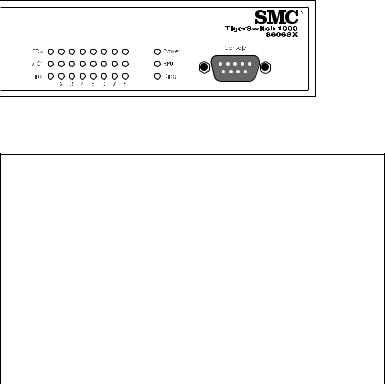
ABOUT THE TIGERSWITCH 1000
Figure 1-1. Front and Rear Panels
Description of Hardware
1000BASE-SX Ports
These ports are SC-type fiber optic ports that operate at 1 Gbps full and half duplex. The ports can be connected to other IEEE 802.3z-compliant devices up to 550 m (1805 ft.) away using fiber optic cable. The switch is fitted with SC ports, but you can also attach an ST plug to the switch using SMC’s optional SC-ST Converter (Part Number: 99-012034-091).
GBIC Slots
The two slots on the switch front panel are for installing optional 5V GBIC transceivers. Note that GBIC transceivers are hot-swappable. You do not need to power off the switch before installing or removing a transceiver.
1-2
ABOUT THE TIGERSWITCH 1000
Status LEDs
The LEDs, which are located on the front panel for easy viewing, are shown below and described in the following table.
Figure 1-2. Port and System LEDs
Port and System Status LEDs
LED |
Condition |
Status |
|
|
|
Power |
On Green |
Switch is receiving power. |
|
|
|
|
Off |
Power off or failure. |
|
|
|
RPU |
On Green |
Redundant power unit is attached and |
|
|
is operating in a load-sharing mode. |
|
|
|
|
Off |
Power off or failure. |
|
|
|
Diag. |
Flashing Green |
System self-diagnostic test in progress. |
|
|
|
|
On Green |
System self-diagnostic test successfully |
|
|
completed. |
|
|
|
|
On Amber |
System self-diagnostic test has failed. |
|
|
|
1-3

ABOUT THE TIGERSWITCH 1000
Port and System Status LEDs
LED |
Condition |
Status |
|
|
|
Ports |
|
|
|
|
|
Link |
Flashing Green |
Port is operating at 1000 Mbps. |
|
|
|
|
Flashing Amber |
Port has been manually disabled. |
|
|
|
|
Off |
There is no valid link on the port. |
|
|
|
ACT |
On Green |
Traffic is passing through the port. |
|
|
|
FDX |
On Green |
Port is operating at full duplex. |
|
|
|
|
On Amber |
Port is operating in half-duplex mode. |
|
|
|
Network Management Agent
The TigerSwitch 1000 includes a built-in network management agent. The agent offers a variety of management options, including SNMP, RMON and a Web-based interface. The switch also provides a serial port on the rear panel for out-of-band management. This is an RS-232 serial port with a DB-9 connector. A PC may be connected to this port for configuration and monitoring purposes out-of band via a full-handshaking null-modem cable. (See Appendix B for a description of wiring options.)
The network management agent provides a wide range of advanced performance-enhancing features. Port-based and tagged VLANs provide traffic security and efficient use of network bandwidth. QoS priority queueing ensures the minimum delay for moving real-time multi-media data across the network. Flow control eliminates the loss of packets due to bottlenecks caused by port saturation. And broadcast storm suppression prevents broadcast traffic storms from engulfing the network. Some of the management features are described below. For a detailed description, refer to the Management Guide that is included with the switch.
1-4
ABOUT THE TIGERSWITCH 1000
Spanning Tree Protocol
The TigerSwitch 1000 supports ANSI/IEEE 802.1d Spanning Tree Protocol. This protocol adds a level of fault tolerance by allowing two or more redundant connections to be created between a pair of LAN segments. When there are multiple physical paths between segments, the protocol will choose a single path and disable all others to ensure that only one route exists between any two stations on the network. This prevents the creation of network loops. However, if the chosen path should fail for any reason, an alternate path will be activated to maintain the connection.
The default setting for the Spanning Tree Protocol is “enabled.” This protocol may be configured (enabled or disabled) out-of-band via the serial console port or in-band via the Web interface, Telnet, or SNMP network management software.
VLANs
The TigerSwitch 1000 supports up to 256 VLANs. A Virtual LAN is a collection of network nodes that share the same collision domain regardless of their physical location or connection point in the network. By segmenting your network into VLANs, you can:
•Eliminate broadcast storms which severly degrade performance in a flat network.
•Simplify network management for node changes/moves by remotely configuring VLAN membership for the concerned port, rather than having to manually change the node’s IP address.
•Provide data security by restricting all traffic to the originating VLAN, except where a connection has been configured between separate VLANs using a router or Layer 3 switch.
1-5

ABOUT THE TIGERSWITCH 1000
Multicast Switching
Specific multicast traffic can be assigned to its own VLAN to ensure that it does not interfere with normal network traffic and to guarantee real-time delivery by setting the required priority level for the designated VLAN. The switch uses IGMP Snooping and IGMP to manage multicast group registration.
Traffic Priority
This switch provides Quality of Service (QoS) by prioritizing each packet based on the required level of service, using two distinct categories with Weighted Fair Queuing. It uses IEEE 802.1Q and 802.1p tags to prioritize incomming traffic based on input from the end-station application driver. These functions can be used, for example, to provide independent priorities for real-time video, real-time voice, guaranteed-delivery data, or best-effort data.
Optional Redundant Power Unit
SMC provides an optional Redundant Power Unit (RPU), SMCRPU150W, that can supply power to the switch in the event of failure of the internal power supply.
Power Supply Receptacles
There are two power receptacles on the rear panel of the switch. The standard power receptacle is for the AC power cord. The receptacle labeled “DC Input” is for the optional Redundant Power Unit (RPU).
Figure 1-3. Power Supply Receptacles
1-6
Loading...