


 Loading...
INSTALLATION
GUIDE
802.11a/b/g/n Outdoor Dual-Band Wireless Access Point
SMC2890W-AN, SMC2891W-AN

Outdoor Access Point
Installation Guide
No. 1, Creation Road III, |
|
Hsinchu Science Park, |
|
30077, Taiwan, R.O.C. |
July 2013 |
Tel: +886 3 5638888 |
Pub. # 149100000208A |
Fax: +886 3 6686111 |
E072013-CS-R02 |
Information furnished by SMC Networks, Inc. (SMC) is believed to be accurate and reliable. However, no responsibility is assumed by SMC for its use, nor for any infringements of patents or other rights of third parties which may result from its use. No license is granted by implication or otherwise under any patent or patent rights of SMC. SMC reserves the right to change specifications at any time without notice.
Copyright © 2013 by
SMC Networks, Inc.
No. 1 Creation Road III,
Hsinchu Science Park,
30077, Taiwan, R.O.C.
All rights reserved
Trademarks:
SMC is a registered trademark; and Barricade, EZ Switch, TigerStack, TigerSwitch, and TigerAccess are trademarks of SMC Networks, Inc. Other product and company names are trademarks or registered trademarks of their respective holders.

Warranty and Product
Registration
To register SMC products and to review the detailed warranty statement, please refer to the Support Section of the SMC Website at http://www.smc.com.
– 4 –

How to Use This Guide
Who Should Read This
Guide?
How This Guide is Organized
This guide includes detailed information on the Access Point (AP) hardware, including network ports, power, cabling requirements, as well as plug-in transceivers. This guide also provides general installation guidelines and recommended procedures. To deploy this AP effectively and ensure trouble-free operation, you should first read the relevant sections in this guide so that you are familiar with all its hardware components.
This guide is for network administrators and support personnel that install, operate and maintain network equipment. The guide assumes a basic working knowledge of LANs (Local Area Networks) and can be read by those that are new to network equipment, or those with more experience.
This organization of this guide is based on the AP’s main hardware components. Each chapter includes information about a specific component with relevant specifications and installation procedures. An AP overview section is also provided.
For Users New to APs — If you are new to APs, it is recommended that you first read all chapters in this guide before installing the AP.
For Experienced Users — If you are already familiar with installing and operating network APs, Chapters 1 and 2 provide you with enough information to install the AP. Other chapters can be left for reference, when needed.
The guide includes these chapters:
Chapter 1 - Access Point Overview — Includes an AP overview, key component identification, and key technical specifications.
Chapter 2 - Installation Overview — Includes information on the package contents, system configuration, and an outline of AP installation tasks.
Chapter 3 - AP Chassis — Includes AP installaion for pole or wall, and external antenna connection.
Chapter 4 - Power and Grounding — Includes information on PoE power for the unit, AP grounding, and powering on the AP.
Chapter 5 - Network Connections — Includes information on network interfaces, installing optional transceivers, and cabling specifications.
– 5 –

How to Use This Guide
Chapter 6 - AP Management — Connecting to the AP for management and information on the system status LEDs.
Appendix A - Troubleshooting — Information for troubleshooting AP installation and operation.
Related This guide focuses on AP hardware and installation, it does not cover software Documentation configuration of the AP. For specific information on how to operate and use the
management functions of the AP, see the following guide:
Management Guide
For all safety information and regulatory statements, see the following documents:
Quick Start Guide
Safety and Regulatory Information
Conventions The following conventions are used throughout this guide to show information:
Note: Emphasizes important information or calls your attention to related features or instructions.
Caution: Alerts you to a potential hazard that could cause loss of data, or damage the system or equipment.
Warning: Alerts you to a potential hazard that could cause personal injury.
Revision History This section summarizes the changes in each revision of this guide.
July 2013 Revision
This is the second revision of this guide. It includes the following change:
Added information on antenna placement.
Added information on using the antenna connector covers.
January 2013 Revision
This is the first revision of this guide.
– 6 –

Contents
|
Warranty and Product Registration |
4 |
|
How to Use This Guide |
5 |
|
Contents |
7 |
|
Figures |
9 |
|
Tables |
10 |
1 |
Access Point Overview |
11 |
|
Hardware Description |
11 |
|
Key Hardware Components |
12 |
|
Key Technical Specifications |
15 |
2 |
Installation Overview |
16 |
|
Package Contents |
16 |
|
System Configuration |
17 |
|
AP Installation Tasks |
18 |
3 |
AP Chassis |
23 |
|
General Installation Guidelines |
23 |
|
Antenna Position |
23 |
|
Ethernet Cabling |
24 |
|
Radio Interference |
24 |
|
Weather Conditions |
24 |
|
How to Mount the Unit |
25 |
|
How to Pole Mount |
25 |
|
How to Connect External Antennas |
27 |
|
How to Align Antennas |
28 |
4 |
Power and Grounding |
31 |
|
Power Injector Module |
31 |
– 7 –

Contents
|
How to Ground the Unit |
33 |
|
How to Install the Power Injector |
34 |
5 |
Network Connections |
37 |
|
Understanding the Network Status LEDs |
38 |
|
How to Connect to Radio Interfaces |
38 |
|
How to Connect to the RJ-45 Port |
39 |
|
Copper Cabling Guidelines |
39 |
|
10/100BASE-TX Pin Assignments |
39 |
|
1000BASE-T Pin Assignments |
40 |
|
Connection Procedure |
41 |
|
Grounding the Ethernet Cable |
43 |
6 |
AP Management |
45 |
|
Understanding the System Status LEDs |
46 |
|
How to Connect to the Console Port |
47 |
A |
Troubleshooting |
49 |
|
Diagnosing LED Indicators |
49 |
|
System Self-Diagnostic Test Failure |
49 |
|
Power Problems |
49 |
|
Installation |
50 |
|
Wireless Connection Problems |
50 |
|
In-Band Access |
50 |
|
Out-of-Band Access |
51 |
|
Reset the Access Point |
51 |
|
Index |
52 |
– 8 –

Figures
Figure 1: |
SMC2891W-AN Outdoor Access Point |
11 |
Figure 2: |
Bottom Panel View |
12 |
Figure 3: |
Top Panel View (SMC2891W-AN) |
13 |
Figure 4: |
Power Injector Module |
14 |
Figure 5: |
System Configuration |
17 |
Figure 6: |
Installing the AP on a Pole |
18 |
Figure 7: |
Making a Connection to the RJ-45 Port |
19 |
Figure 8: |
Connecting AC Power |
20 |
Figure 9: |
System LEDs |
20 |
Figure 10: |
Console Port |
21 |
Figure 11: |
Attach Bracket to Pole |
25 |
Figure 12: |
Attach Bracket to AP |
26 |
Figure 13: |
Mount the AP on the Pole |
26 |
Figure 14: |
Antenna Connector Covers |
27 |
Figure 15: |
Connect External Antennas |
28 |
Figure 16: |
PoE Power Injector |
31 |
Figure 17: |
Ground Wire Connection |
33 |
Figure 18: |
Connecting the Power Injector |
34 |
Figure 19: |
Network Status LEDs |
38 |
Figure 20: |
RJ-45 Connector |
39 |
Figure 21: |
Waterproof RJ-45 Port Cover |
42 |
Figure 22: |
Making a Connection to the RJ-45 Port |
43 |
Figure 23: |
Outdoor-Rated Ethernet Cable Drain Wire |
44 |
Figure 24: |
System Status LEDs |
46 |
Figure 25: |
Console Port Connection |
48 |
– 9 –

Tables
Table 1: Key Technical Specifications |
15 |
Table 2: Power Injector Module Specifications |
32 |
Table 3: Power Injector Module Status LED |
32 |
Table 4: Network Status LEDs |
38 |
Table 5: 10/100BASE-TX MDI and MDI-X Port Pinouts |
40 |
Table 6: 1000BASE-T MDI and MDI-X Port Pinouts |
41 |
Table 7: System Status LEDs |
46 |
Table 8: Console Cable Wiring |
47 |
Table 9: Troubleshooting Chart |
49 |
– 10 –
1 |
Access Point Overview |
This chapter includes these sections:
“Hardware Description” on page 11
“Key Technical Specifications” on page 15
Hardware Description
The SMC2890W-AN/SMC2891W-AN outdoor access point (AP) is built with leadingedge technology to deliver reliable high-performance connectivity for your data network.
The SMC2890W-AN/SMC2891W-AN is a dual-band IEEE 802.a/b/g/n AP that is designed to deliver high-performance wireless services for clients or to provide bridge links between remote LANs. Housed in a weatherproof enclosure for mounting outdoors, the unit includes its own bracket for attaching to a pole, radio mast, or tower structure. The unit is powered through its Ethernet cable connection from a power injector module that is installed indoors.
In addition, the AP offers full network management capabilities through an easy- to-use web interface, a command-line interface, and support for Simple Network Management Protocol (SNMP) tools.
Figure 1: SMC2891W-AN Outdoor Access Point
– 11 –

Chapter 1 | Access Point Overview
Hardware Description
Key Hardware
Components
The SMC2890W-AN/SMC2891W-AN consists of serveral key harware components. This manual describes each specific component, or related components, together with their installation requirements and procedures in each chapter. To understand each component in detail, refer to the relevant section.
Figure 2: Bottom Panel View
Built-in 5 GHz Antenna (SMC2891W-AN only) |
RJ-45 PoE Port |
Console Port with Waterproof Cover |
Water-Tight Test Point (DO NOT REMOVE) |
Back Panel System LEDs (Not Visible in Figure) |
|
Built-in 5 GHz Antenna
The SMC2891W-AN AP includes an integrated 5 GHz antenna. For more information, see “How to Align Antennas” on page 28.
Console Port
The port labeled “Console” provides an out-of-band serial connection to a terminal or a PC running terminal emulation software. The port can be used for performing unit monitoring and configuration. For more information, see “How to Connect to the Console Port” on page 47.
RJ-45 PoE Port
The RJ-45 port labeled “PoE” provides a 1000BASE-T data and Power-over-Ethernet (PoE) power connection to the unit. For more information, see “How to Connect to the RJ-45 Port” on page 39.
– 12 –

Chapter 1 | Access Point Overview
Hardware Description
System LEDs
For information on system status LED indicators, see “Understanding the System Status LEDs” on page 46.
Water-Tight Test Point
Caution: Do not remove or loosen this screw. Doing so could lead to damage of the unit.
Figure 3: Top Panel View (SMC2891W-AN)
External Antenna Connectors |
Pole/Wall Bracket Attachment Point |
Ground Point
External Antenna Connectors
The SMC2890W-AN AP unit includes four external antenna connectors, two are for the 2.4 GHz radio and two for the 5 GHz radio. The SMC2891W-AN AP unit includes three external antenna connectors, two are for the 2.4 GHz radio and one for the 5 GHz radio (the unit also includes a built-in 5 GHz antenna). For more information, see “How to Connect External Antennas” on page 27.
Ground Point
There is a ground point for grounding the AP chassis to earth. For more information, see “How to Ground the Unit” on page 33.
– 13 –
Chapter 1 | Access Point Overview
Hardware Description
Pole Mounting Bracket
The included Mounting Bracket Kit can be used to mount the unit on a 1.5 to 6 inch diameter pole, or to part of a radio mast or tower structure. For more information, see “How to Mount the Unit” on page 25.
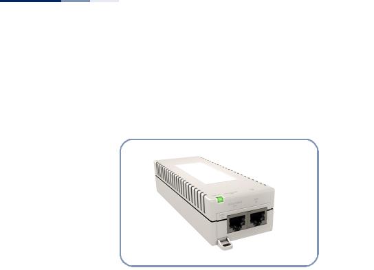
Figure 4: Power Injector Module
Power Injector Module
The AP receives power through a PoE connection to its RJ-45 port. The PoE power is supplied from a power injector module that is installed indoors. For information, see “Power Injector Module” on page 31.
– 14 –

Chapter 1 | Access Point Overview
Key Technical Specifications
Key Technical Specifications
The following table contains key system specifications for the AP.
Table 1: Key Technical Specifications
Item |
Specification |
|
|
Ports |
One 10/100/1000 Mbps RJ-45 port |
Network Interface |
RJ-45 Port: 1000BASE-T, PoE (PD) with waterproof cover |
Console Port |
RS-232, RJ-45 waterproof connector |
2.4GHz Radio |
IEEE 802.11b/g/n |
5 GHz Radio |
IEEE 802.11a/n |
External Antennas |
4 N-Type female connecters (50 Ohms), 2x2 MIMO for 2.4 and 5 GHz |
Integrated Antenna |
12 dBi @ 5 GHz, panel type, horizontal polarization |
(SMC2891W-AN only) |
|
Radio Frequencies |
2400 ~ 2483.5 MHz |
|
2412 ~ 2472 MHz |
|
5745 ~ 5825 MHz (China) |
|
5180 ~ 5320 MHz (ETSI) |
|
5500 ~ 5700 MHz (ETSI) |
LEDs |
Power/System, Ethernet, 2.4GHz, 5GHz |
PoE Input Power |
38~57 VDC |
Power Consumption |
25.5 W maximum for IEEE 802.3at |
|
12.95 W maximum for IEEE 802.3af |
Weight |
1.7 kg (3.75 lbs), unit without bracket or external antennas |
Size |
W x D x H: 195 x 190 x 74 mm (7.68 x 7.48 x 2.91 inches) |
Temperature |
Operating: -10 °C to 60 °C (-14 °F to 140 °F) |
|
Storage: -20 °C to 70 °C (-4 °F to 158 °F) |
Humidity |
Operating: 10% to 95% (non-condensing) |
Wind Velocity |
Operational: 100 MPH (Miles per hour) / 44 mps |
|
Survival: 150 MPH / 66 mps |
|
|
– 15 –

2 |
Installation Overview |
This chapter includes these sections:
“Package Contents” on page 16
“System Configuration” on page 17
“AP Installation Tasks” on page 18
Package Contents
After unpacking the AP, check the contents to be sure you have received all the components.
SMC2890W-AN or SMC2891W-AN Outdoor Access Point
Bracket Mounting Kit for pole mounting
PoE Power Injector with power cord—either US, Continental Europe or UK
Waterproof RJ-45 port cover
Console cable (RJ-45 to DB-9)
Quick Start Guide
Regulatory and Safety Information
Documentation CD — includes Installation Guide and Management Guide
Note that the following items are available options for the AP:
(Optional) Two external 2.4 GHz antennas
(Optional) One external 5 GHz antenna
(Optional) One mounting kit for 5 GHz external antenna
(Optional) 1.5 m low-loss 200 RF cable for 5 GHz external antenna
– 16 –

Chapter 2 | Installation Overview
System Configuration
System Configuration
At each location where a unit is installed it must be connected to the local network, either by using the power injector module, or by a direct connection to an
IEEE 802.3at-compliant LAN switch.
The following figure illustrates the system component connections.
Figure 5: System Configuration
|
External Antenna |
Indoor |
Outdoor |
LAN Switch |
AP Unit |
|
Ethernet |
Ethernet Cable |
Cable |
Power |
|
Injector |
|
AC Power |
Ground Wire |
|
– 17 –
Loading...