

Page 1
OperatingManual
SUNNY BOY 1.5 / 2.5
SB15-25-BE-en-10 | Version 1.0
ENGLISH
Page 2

Legal Provisions
SMA Solar Technology AG
Legal Provisions
The information contained in these documents is property of SMA Solar Technology AG. Any
publication, whether in whole or in part, requires prior written approval by SMA Solar Technology
AG. Internal reproduction used solely for the purpose of product evaluation or other proper use is
allowed and does not require prior approval.
SMA Warranty
You can download the current warranty conditions from the Internet at www.SMA-Solar.com.
Trademarks
All trademarks are recognized, even if not explicitly identified as such. A lack of identification does
not mean that a product or symbol is not trademarked.
The BLUETOOTH® word mark and logos are registered trademarks of BluetoothSIG,Inc. and any
use of these marks by SMASolarTechnologyAG is under license.
Modbus® is a registered trademark of Schneider Electric and is licensed by the Modbus
Organization, Inc.
QR Code is a registered trademark of DENSO WAVE INCORPORATED.
Phillips® and Pozidriv® are registered trademarks of Phillips Screw Company.
Torx® is a registered trademark of Acument Global Technologies, Inc.
SMASolarTechnologyAG
Sonnenallee 1
34266 Niestetal
Germany
Tel. +49 561 9522-0
Fax +49 561 9522-100
www.SMA.de
E-mail: info@SMA.de
© 2004 to 2015SMASolarTechnologyAG. All rights reserved.
Operating ManualSB15-25-BE-en-102
Page 3

SMA Solar Technology AG
Table of Contents
Table of Contents
1 Information on this Document ................................................. 5
1.1 Validity................................................................................................ 5
1.2 Target Group...................................................................................... 5
1.3 Additional Information....................................................................... 5
1.4 Symbols .............................................................................................. 6
1.5 Nomenclature..................................................................................... 6
1.6 Typographies...................................................................................... 6
2 Safety......................................................................................... 7
2.1 Intended Use ...................................................................................... 7
2.2 Safety Information.............................................................................. 7
3 Scope of Delivery...................................................................... 9
4 Product Description................................................................... 10
4.1 Sunny Boy........................................................................................... 10
4.2 Interfaces and Functions .................................................................... 13
4.3 LED Signals......................................................................................... 15
5 Mounting ................................................................................... 16
5.1 Requirements for Mounting ............................................................... 16
5.2 Mounting the Inverter......................................................................... 18
6 Electrical Connection................................................................. 20
6.1 Safety during Electrical Connection.................................................. 20
6.2 Overview of the Connection Area .................................................... 21
6.3 AC Connection................................................................................... 21
6.3.1 Requirements for the AC Connection............................................ 21
6.3.2 Connecting the Inverter to the Utility Grid.................................... 23
6.3.3 Connecting Additional Grounding ............................................... 25
6.4 Connecting the Inverter to the Network ........................................... 26
6.5 DC Connection................................................................................... 28
6.5.1 Requirements for the DC Connection............................................ 28
6.5.2 Assembling the DC Connectors .................................................... 29
6.5.3 Connecting the PV Array............................................................... 30
Operating Manual 3SB15-25-BE-en-10
Page 4

Table of Contents
6.5.4 Disassembling the DC Connectors................................................ 31
SMA Solar Technology AG
7 Commissioning the Inverter ..................................................... 33
8 Using the Inverter User Interface ............................................ 34
8.1 Calling Up the Inverter User Interface .............................................. 34
8.1.1 Calling Up the Inverter User Interface via Direct Connection..... 34
8.1.2 Calling Up the Inverter User Interface in the Local Network ...... 36
8.2 Design of the Inverter User Interface ................................................ 37
8.3 Changing the Password..................................................................... 39
8.4 Forgotten Password............................................................................ 40
9 Configuration ............................................................................ 41
9.1 Configuration Procedure.................................................................... 41
9.2 Starting the Installation Assistant....................................................... 41
9.3 Starting the Self-Test (For Italy Only) ................................................ 42
9.4 Activating the Receipt of Control Signals (Only for Italy)................ 42
9.5 Deactivating Grounding Conductor Monitoring.............................. 43
9.6 Setting SMA OptiTrac Global Peak ................................................. 43
9.7 Saving the Configuration in a File..................................................... 44
9.8 Adopting a Configuration from a File............................................... 44
9.9 Updating the Firmware...................................................................... 44
9.10 Integrating the Inverter into the Network.......................................... 45
9.11 Setting the Date and Device Time..................................................... 45
9.12 Configuring the Energy Meter........................................................... 45
9.13 Configuring Feed-In Management.................................................... 46
9.14 Changing Operating Parameters...................................................... 46
9.15 Configuring the Country Data Set..................................................... 47
9.16 Switching the Dynamic Power Display Off....................................... 48
9.17 Switching WLAN Off......................................................................... 48
9.18 Switching WLAN On......................................................................... 48
10 Disconnecting the Inverter from Voltage Sources.................. 50
11 Technical Data........................................................................... 52
12 Contact....................................................................................... 57
Operating ManualSB15-25-BE-en-104
Page 5
SMA Solar Technology AG
1 Information on this Document
1 Information on this Document
1.1 Validity
This document is valid for the following device types from firmware version 2.0.1.R:
• SB1.5-1VL-40 (Sunny Boy 1.5)
• SB2.5-1VL-40 (Sunny Boy 2.5)
1.2 Target Group
This document is intended for qualified persons and end users. Only qualified persons are allowed
to perform the activities marked in this document with a warning symbol and the caption
"Qualifiedperson". Tasks that do not require any particular qualification are not marked and can
also be performed by end users. Qualified persons must have the following skills:
• Knowledge of how an inverter works and is operated
• Training in how to deal with the dangers and risks associated with installing and using
electrical devices and installations
• Training in the installation and commissioning of electrical devices and installations
• Knowledge of the applicable standards and directives
• Knowledge of and compliance with this document and all safety information
1.3 Additional Information
Links to additional information can be found at www.SMA-Solar.com:
Document title Document type
Troubleshooting, Cleaning and Decommissioning Service Manual
"Efficiency and Derating"
Efficiency and Derating Behavior of the SunnyBoy, SunnyTripower
and SunnyMiniCentral Inverters
"Application for SMAGridGuard Code" Certificate
"Circuit Breaker"
Dimensioning and Selection of a Suitable AC Circuit Breaker for Inverters under PV-Specific Influences
"Criteria for Selecting a Residual-Current Device" Technical Information
"Temperature Derating"
Causes of Temperature Derating and Possible Corrective Measures
"Overvoltage Protection"
Measures For Lightning and Overvoltage Protection in PV Systems
"Webconnect Systems in SunnyPortal"
Registration in SunnyPortal
Technical Information
Technical Information
Technical Information
Technical Information
User Manual
Operating Manual 5SB15-25-BE-en-10
Page 6
1 Information on this Document
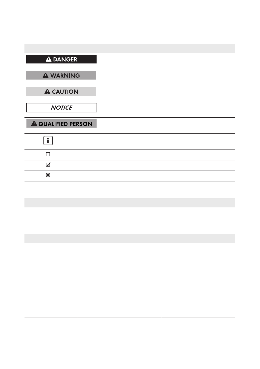
1.4 Symbols
Symbol Explanation
Indicates a hazardous situation which, if not
avoided, will result in death or serious injury
Indicates a hazardous situation which, if not
avoided, can result in death or serious injury
Indicates a hazardous situation which, if not
avoided, can result in minor or moderate injury
Indicates a situation which, if not avoided, can result in property damage
Sections describing activities to be performed by
qualified persons only
Information that is important for a specific topic or
goal, but is not safety-relevant
Indicates a requirement for meeting a specific goal
Desired result
A problem that might occur
1.5 Nomenclature
SMA Solar Technology AG
Complete designation Designation in this document
SunnyBoy Inverter, product
1.6 Typographies
Typography Use Example
bold
>
[Button]
[Key]
• Display texts
• Elements on a user interface
• Terminals
• Elements to be selected
• Elements to be entered
• Connects several elements to be
selected
• Button or key to be selected or
pressed
• The value can be found in
the field Energy.
• Select Settings.
• Enter 10 in the field
Minutes.
• Select Settings > Date.
• Select [Next].
Operating ManualSB15-25-BE-en-106
Page 7

SMA Solar Technology AG
2 Safety
2 Safety
2.1 Intended Use
The Sunny Boy is a transformerless PV inverter which converts the direct current of the PV array to
grid-compliant alternating current and feeds it into the utility grid.
The product is suitable for indoor and outdoor use.
The product must only be operated with PV arrays of protection class II in accordance with
IEC61730, application class A. The PV modules must be compatible with this product.
PV modules with a high capacity to ground must only be used if their coupling capacity does not
exceed 900nF (for information on how to calculate the coupling capacity, see the Technical
Information "Leading Leakage Currents" at www.SMA-Solar.com).
All components must remain within their permitted operating ranges at all times.
The product must only be used in countries for which it is approved or released by SMA Solar
Technology AG and the grid operator.
Use this product only in accordance with the information provided in the enclosed documentation
and with the locally applicable standards and directives. Any other application may cause
personal injury or property damage.
Alterations to the product, e.g. changes or modifications, are only permitted with the express written
permission of SMA Solar Technology AG. Unauthorized alterations will void guarantee and
warranty claims and usually void the operation permit. SMA Solar Technology AG shall not be
held liable for any damage caused by such changes.
Any use of the product other than that described in the Intended Use section does not qualify as
appropriate.
The enclosed documentation is an integral part of this product. Keep the documentation in a
convenient place for future reference and observe all instructions contained therein.
The type label must remain permanently attached to the product.
2.2 Safety Information
This section contains safety information that must be observed at all times when working on or with
the product.
To prevent personal injury and property damage and to ensure long-term operation of the product,
read this section carefully and observe all safety information at all times.
Operating Manual 7SB15-25-BE-en-10
Page 8
2 Safety
SMA Solar Technology AG
Danger to life due to high voltages of the PV array
When exposed to sunlight, the PV array generates dangerous DC voltage which is present in the
DC conductors and the live components of the inverter. Touching the DC conductors or the live
components can lead to lethal electric shocks. If you disconnect the DC connectors from the
inverter under load, an electric arc may occur leading to electric shock and burns.
• Do not touch non-insulated cable ends.
• Do not touch the DC conductors.
• Do not touch any live components of the inverter.
• Have the inverter mounted, installed and commissioned only by qualified persons with the
appropriate skills.
• If an error occurs, have it rectified by qualified persons only.
• Prior to performing any work on the inverter, disconnect it from all voltage sources as
described in this document (see Section10 "Disconnecting the Inverter from Voltage
Sources", page50).
Danger to life due to high voltages in the inverter
Touching live components within the inverter can lead to lethal electric shocks. Some components
also require at least five minutes to discharge after the inverter has been disconnected from
voltage sources.
• Do not open the inverter.
Danger to life due to electric shock
Touching an ungrounded PV module or array frame can cause a lethal electric shock.
• Connect and ground the PV modules, array frame and electrically conductive surfaces so
that there is continuous conduction. Observe the applicable local regulations.
Damage to the inverter due to the use of cleaning agents
• If the inverter is dirty, clean the enclosure, the enclosure lid, the type label and the LEDs using
only clean water and a cloth.
Operating ManualSB15-25-BE-en-108
Page 9
SMA Solar Technology AG
3 Scope of Delivery
3 Scope of Delivery
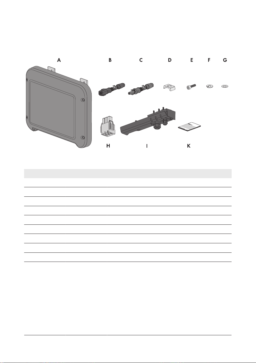
Check the scope of delivery for completeness and any externally visible damage. Contact your
distributor if the scope of delivery is incomplete or damaged.
Figure 1: Components included in the scope of delivery
Position Quantity Designation
A 1 Inverter
B 1 Negative DC connector
C 1 Positive DC connector
D 1 Clamping bracket
E 1 Cylindrical screw M5x16
F 1 Spring lock washer
G 1 Washer
H 1 AC connector
I 1 Connection cap
K 1 Quick reference guide with password label on the rear
side
The label contains the following information:
• PIC (Product Identification Code) identification key
for registering the PV system in SunnyPortal
• RID (Registration Identifier) registration ID for
registering the PV system in SunnyPortal
• WLAN password WPA2-PSK (Wi-Fi Protected Access
2 - Preshared Key) for direct access to the inverter via
WLAN
Operating Manual 9SB15-25-BE-en-10
Page 10
B
A
C
D
4 Product Description
SMA Solar Technology AG
4 Product Description
4.1 Sunny Boy
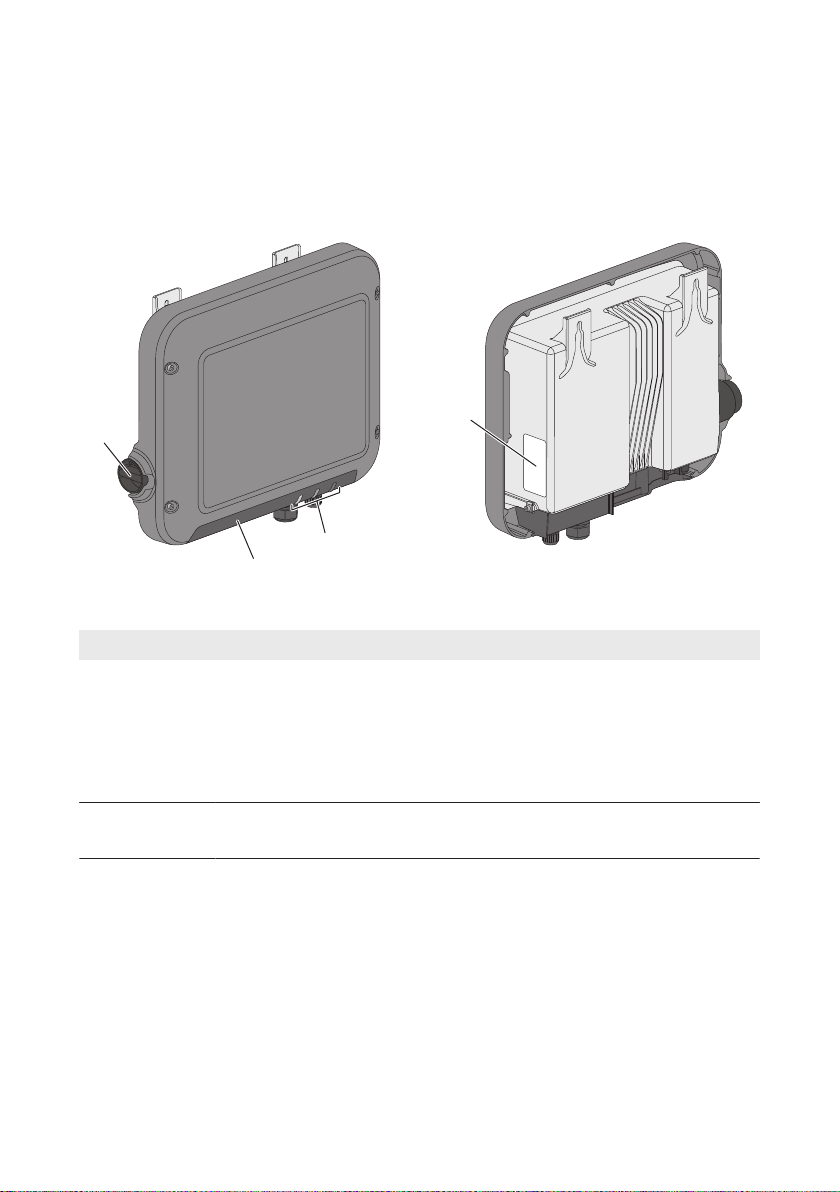
The Sunny Boy is a transformerless PV inverter which converts the direct current of the PV array to
grid-compliant alternating current and feeds it into the utility grid.
Figure 2: Design of the SunnyBoy
Position Designation
A DC Load-Break Switch
The inverter is equipped with a DC load-break switch. If the DC load-break
switch is set to the position I, it establishes a conductive connection between
the PV array and the inverter. Setting the DC load-break switch to the O position interrupts the DC electric circuit and completely disconnects the PV array
from the inverter. Disconnection takes place at all poles.
B LEDs
The LEDs indicate the operating state of the inverter.
Operating ManualSB15-25-BE-en-1010
Page 11
SMA Solar Technology AG
Position Designation
C Connection cap
Connection area with cable glands for connection to the utility grid and the local network
D Type label
The type label uniquely identifies the inverter. You will require the information
on the type label to use the product safely and when seeking customer support from the SMAServiceLine. The type label must remain permanently attached to the product. You will find the following information on the type label:
• Device type (Model)
• Serial number (SerialNo.)
• Date of manufacture
• Identification key (PIC) for registration in Sunny Portal
• registration ID (RID) for registration in Sunny Portal
• WLAN password (WPA2-PSK) for direct access to the inverter via WLAN
• Device-specific characteristics
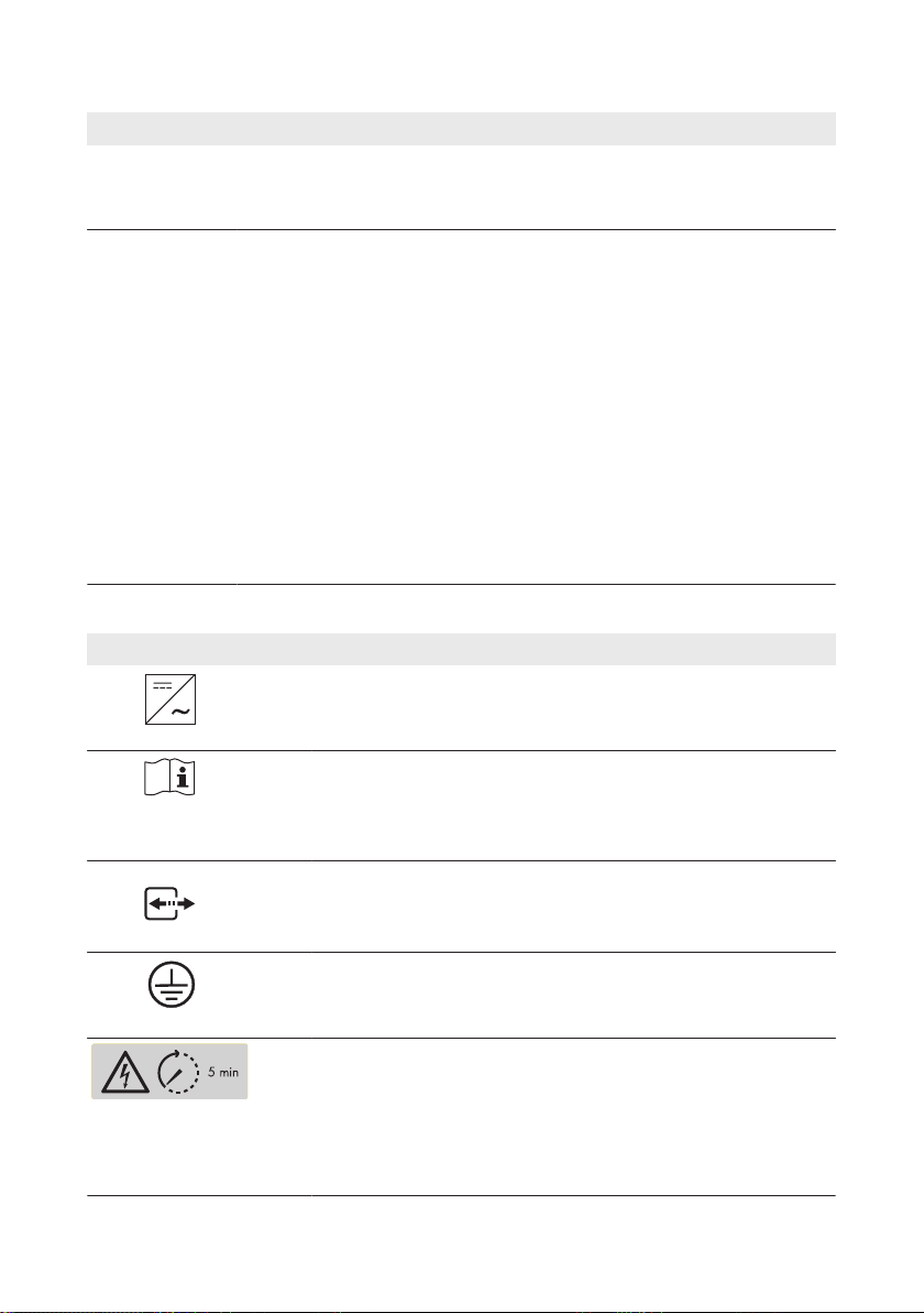
Symbols on the Inverter and on the Type Label
Symbol Explanation
Inverter
Together with the green LED, this symbol indicates the operating
state of the inverter
Observe the documentation
Together with the red LED, this symbol indicates an error (for information regarding troubleshooting, see the service manual at
www.SMA-Solar.com)
Data transmission
Together with the blue LED, this symbol indicates that the inverter
has an active network connection
4 Product Description
Grounding conductor
This symbol indicates the position for connecting a grounding con-
ductor.
Danger to life due to high voltages in the inverter; observe the wait-
ing time of fiveminutes
High voltages that can cause lethal electric shocks are present in the
live components of the inverter. Prior to performing any work on the
inverter, disconnect it from all voltage sources as described in this
document (see Section10, page50).
Operating Manual 11SB15-25-BE-en-10
Page 12
4 Product Description
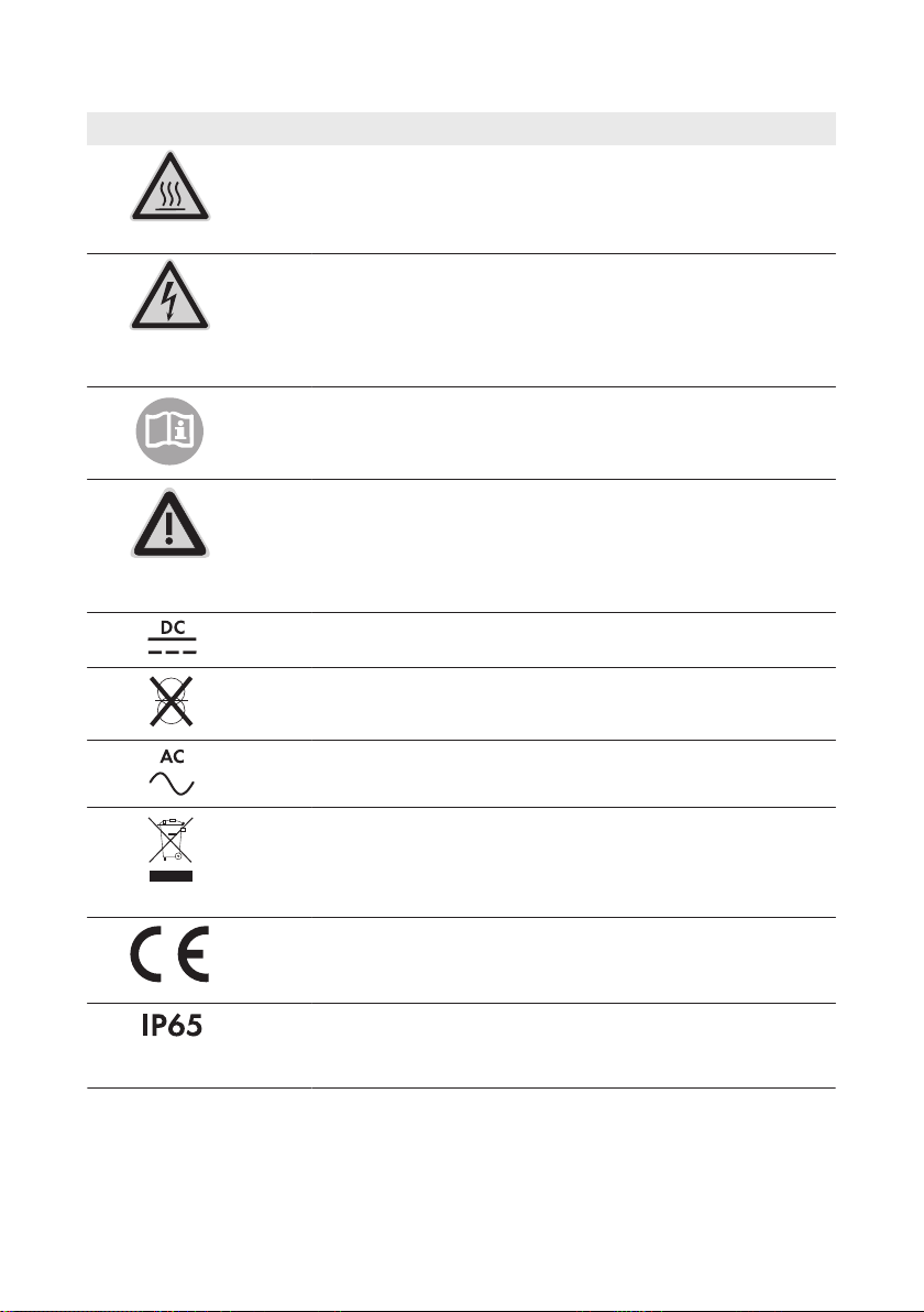
Symbol Explanation
Risk of burns due to hot surfaces
The product can get hot during operation. Avoid contact during op-
eration. Prior to performing any work on the product, allow the product to cool down sufficiently.
Danger to life due to electric shock
The product operates at high voltages. Prior to performing any work
on the product, disconnect the product from voltage sources. All
work on the product must be carried out by electrically qualified persons only.
Observe the documentation
Observe all documentation supplied with the product.
Danger
This symbol indicates that the inverter must be additionally grounded
if additional grounding or equipotential bonding is required at the
installation site (see Section6.3.3 "Connecting Additional Grounding", page25).
Direct current
The product does not have a transformer.
SMA Solar Technology AG
Alternating current
WEEE designation
Do not dispose of the product together with the household waste but
in accordance with the disposal regulations for electronic waste applicable at the installation site.
CE marking
The product complies with the requirements of the applicable EU di-
rectives.
Degree of protectionIP65
The product is protected against dust intrusion and water jets from
any angle.
Operating ManualSB15-25-BE-en-1012
Page 13
SMA Solar Technology AG
Symbol Explanation
The product is suitable for outdoor installation.
RCM (Regulatory Compliance Mark)
The product complies with the requirements of the applicable Aus-
tralian standards.
4 Product Description
4.2 Interfaces and Functions
The inverter is equipped with the following interfaces and functions:
Web server with user interface for configuration
The inverter is equipped as standard with an integrated web server that enables configuration of
the inverter via an individual user interface. The inverter user interface can be called up directly via
the web browser in a computer, tablet PC or smartphone so long as there is a WLAN or Ethernet
connection (see Section8 "Using the Inverter User Interface", page34).
SMA Speedwire
The inverter is equipped with SMA Speedwire as standard. SMA Speedwire is a type of
communication based on the Ethernet standard. This enables inverter-optimized 10/100Mbit data
transmission between Speedwire devices in PV systems and the inverter user interface.
Webconnect
The inverter is equipped with a Webconnect function as standard. The Webconnect function
enables direct data transmission between the inverters of a small-scale system and the Internet
portal SunnyPortal without any additional communication device and for a maximum of four
inverters per SunnyPortal system. In large-scale PV power plants, data transmission between
inverters and the Internet portal SunnyPortal is carried out via the SunnyHomeManager. You can
access your SunnyPortal system from any computer with an Internet connection.
Webconnect enables - for PV systems operated in Italy - the connection or disconnection of the
inverter to or from the utility grid and the specifying of the frequency limits to be used via
IEC61850-GOOSE messages.
WLAN
The inverter is equipped with a WLAN interface as standard. The inverter is delivered with the
WLAN interface activated as standard. If you do not want to use WLAN, you can deactivate the
WLAN interface (see Section9.17 "Switching WLAN Off", page48). In addition, the inverter has
a WPS (WiFi Protected Setup) function. The WPS function connects the inverter automatically with
an end device (e.g. smartphone, tablet PC or computer). You can activate the WPS function by
tapping on the enclosure lid twice in quick succession. The open interface will then be signalized
via the rapid flashing of the blue LED on the inverter.
Operating Manual 13SB15-25-BE-en-10
Page 14

4 Product Description
Limited function in the event of frost
The integrated WLAN interface is only designed for temperatures down to -20°C.
• Deactivate the WLAN interface at low temperatures (see Section9.17 "Switching WLAN
Off", page48).
SMA Solar Technology AG
Grid Management Services
The inverter is equipped with service functions for grid management.
Depending on the requirements of the grid operator, you can activate and configure the functions
(e.g. active power limitation) via operating parameters.
SMAOptiTracGlobalPeak
SMAOptiTracGlobalPeak is an advancement of SMAOptiTrac and allows the operating point of
the inverter to follow the optimal operating point of the PV array (MPP) precisely at all times. In
addition, with the aid of SMAOptiTracGlobalPeak, the inverter detects several maximum power
points in the available operating range, such as may occur particularly with partially shaded
strings. SMA OptiTrac Global Peak is enabled by default.
All-pole sensitive residual-current monitoring unit
The all-pole sensitive residual-current monitoring unit detects alternating and direct differential
currents. In single-phase and three-phase inverters, the integrated differential current sensor detects
the current difference between the neutral conductor and the line conductor(s). If the current
difference increases suddenly, the inverter disconnects from the utility grid.
Connection of the SMAEnergyMeter
If an SMAEnergyMeter is installed in the PV system, the inverter can receive data on the
household energy consumption directly from this.
Operating ManualSB15-25-BE-en-1014
Page 15
SMA Solar Technology AG
4.3 LED Signals
LED Status Explanation
Green LED flashing Waiting for connection conditions
The LED is on for two seconds and then off for two seconds. The conditions for feed-in operation are not yet met.
As soon as the conditions are met, the inverter will start
feed-in operation.
glowing Feed-in operation
(Power: ≥90%, relative to the active power limit set)
The inverter feeds in with a power of at least 90%.
pulsing Feed-in operation
(Power: <90%, relative to the active power limit set)
The inverter feeds in with a power of less than 90%. The
LED flashes on and off uniformly. The higher the power,
the greater the frequency. If required, you can switch the
dynamic power display off (see Section9.16 "Switching
the Dynamic Power Display Off", page48).
Red LED glowing Error
If an error occurs, a distinct error message and the corresponding event number will be displayed in addition on
the inverter user interface or in the communication product. The error must be rectified by a qualified person (for
troubleshooting, see the service manual at www.SMA-Solar.com).
Blue LED flashes slowly for
approx. one
minute
flashes slowly for
approx. two minutes
glowing Communication active
Communication connection is being established
The inverter is establishing a connection to a local network
or creating an Ethernet direct connection to an end device
(e.g. smartphone, tablet PC or computer).
WPS active
The WPS function of the inverter for WLAN direct connec-
tion with an end device (e.g. smartphone, tablet PC or
computer) is active.
There is an active connection with a local network or an
Ethernet direct connection with an end device (e.g. smartphone, tablet PC or computer).
4 Product Description
Operating Manual 15SB15-25-BE-en-10
Page 16
5 Mounting
SMA Solar Technology AG
5 Mounting
5.1 Requirements for Mounting
Requirements for the mounting location:
Danger to life due to fire or explosion
Despite careful construction, electrical devices can cause fires.
• Do not mount the inverter in areas containing highly flammable materials or gases.
• Do not mount the inverter in a potentially explosive atmosphere.
☐ Do not mount the inverter on a pillar.
☐ A solid support surface must be available for mounting, e.g. concrete or masonry.
☐ The support surface must be even. The difference between the outer anchoring points must not
exceed 5mm.
☐ The mounting location must be suitable for the weight and dimensions of the inverter (see
Section11 "Technical Data", page52).
☐ The mounting location should not be exposed to direct solar irradiation. Direct solar irradiation
can cause the inverter to overheat. As a result, the inverter reduces its power output.
☐ The mounting location should be freely and safely accessible at all times without the need for
any auxiliary equipment (such as scaffolding or lifting platforms). Non-fulfillment of these
criteria may restrict servicing.
☐ To ensure optimum operation, the ambient temperature should be between -25°C and 40°C.
☐ Climatic conditions must be met (see Section11 "Technical Data", page52).
Operating ManualSB15-25-BE-en-1016
Page 17
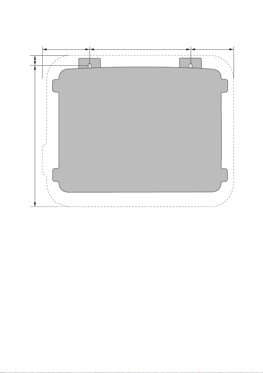
115 mm
105 mm
240 mm
334 mm
23
mm
SMA Solar Technology AG
Dimensions for mounting:
5 Mounting
Figure 3: Position of the anchoring points
Recommended clearances:
If you maintain the recommended clearances, adequate heat dissipation will be ensured. Thus, you
will prevent power reduction due to excessive temperature.
☐ Maintain the recommended clearances to walls as well as to other inverters or objects.
☐ If multiple inverters are mounted in areas with high ambient temperatures, increase the
clearances between the inverters and ensure sufficient fresh-air supply.
Operating Manual 17SB15-25-BE-en-10
Page 18
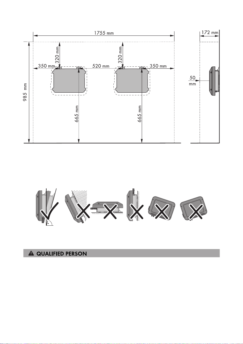
15°
5 Mounting
Figure 4: Recommended clearances
SMA Solar Technology AG
Permitted and prohibited mounting positions:
☐ The inverter must only be mounted in one of the permitted positions. This will ensure that no
moisture can penetrate the inverter.
☐ The inverter should be mounted in such a way that LED signals can be read without difficulty.
Figure 5: Permitted and prohibited mounting positions:
5.2 Mounting the Inverter
Additionally required mounting material (not included in the scope of delivery):
☐ Two stainless steel hexagon head wood screws (AF10, diameter 6mm), screw length must be
suitable for the support surface and the weight of the inverter (fastening bracket thickness:
4mm)
☐ If necessary, two screw anchors suitable for the support surface and the screws
Operating ManualSB15-25-BE-en-1018
Page 19

SMA Solar Technology AG
5 Mounting
Risk of injury when lifting the inverter, or if it is dropped
The inverter weighs 9kg. There is risk of injury if the inverter is lifted incorrectly or dropped while
being transported or when attaching it to or removing it from the wall mounting bracket.
• Transport and lift the inverter carefully.
Procedure:
1.
Risk of injury due to damaged cables
There may be power cables or other supply lines (e.g. gas or water) routed in the wall.
• Ensure that no lines are laid in the wall which could be damaged when drilling holes.
2. Mark the position of the drill holes. Use the information on dimensioning given in this
document for this (see Section5.1 "Requirements for Mounting", page16).
3. Ensure that the positions marked are aligned horizontally.
4. Drill the holes at the positions marked.
5. If necessary, plug the screw anchors into the holes.
6. Screw the screws in so that there is still at least 6mm distance between the screw head and
the mounting surface.
7. Hang the inverter onto the screws using the
metal brackets.
8. Tighten the screws hand-tight using a ratchet or box wrench. When doing this you can
compensate for any misalignment of the drill holes by aligning the metal brackets accordingly.
9. Ensure that the inverter is securely in place.
Operating Manual 19SB15-25-BE-en-10
Page 20

6 Electrical Connection
SMA Solar Technology AG
6 Electrical Connection
6.1 Safety during Electrical Connection
Danger to life due to high voltages of the PV array
When exposed to sunlight, the PV array generates dangerous DC voltage which is present in the
DC conductors and the live components of the inverter. Touching the DC conductors or the live
components can lead to lethal electric shocks. If you disconnect the DC connectors from the
inverter under load, an electric arc may occur leading to electric shock and burns.
• Do not touch non-insulated cable ends.
• Do not touch the DC conductors.
• Do not touch any live components of the inverter.
• Have the inverter mounted, installed and commissioned only by qualified persons with the
appropriate skills.
• If an error occurs, have it rectified by qualified persons only.
• Prior to performing any work on the inverter, disconnect it from all voltage sources as
described in this document (see Section10 "Disconnecting the Inverter from Voltage
Sources", page50).
Damage to the seal of the enclosure lid in sub-zero conditions
If you open the enclosure lid in sub-zero conditions, the sealing of the enclosure lid can be
damaged. This can lead to moisture entering the inverter.
• Do not open the inverter at ambient temperatures lower than -5°C.
• If a layer of ice has formed on the seal of the enclosure lid in sub-zero conditions, remove it
prior to opening the inverter (e.g. by melting the ice with warm air). Observe the applicable
safety regulations.
Operating ManualSB15-25-BE-en-1020
Page 21

C D
A
B
H
G
F
E
SMA Solar Technology AG
6 Electrical Connection
6.2 Overview of the Connection Area
Figure 6: Connection areas and enclosure openings at the bottom of the inverter
Position Designation
A Positive DC connector
B Negative DC connector
C RJ45 pin connector for the network cable
D Pin connector for the AC connector
E Connection of the grounding terminal for additional grounding
F Cable gland for the AC cable
G Cable gland with filler plug for the network cable
H Connection cap
6.3 AC Connection
6.3.1 Requirements for the AC Connection
Cable requirements:
☐ External diameter: 5 mm to 13 mm
☐ Conductor cross-section: 1.5mm² to 4mm²
☐ Insulation stripping length: 15 mm
Operating Manual 21SB15-25-BE-en-10
Page 22

6 Electrical Connection
SMA Solar Technology AG
☐ Sheath stripping length: 70mm
☐ The cable must be dimensioned in accordance with the local and national directives for the
dimensioning of cables. The requirements for the minimum wire size derive from these
directives. Examples of factors influencing cable dimensioning are: nominal AC current, type of
cable, routing method, cable bundling, ambient temperature and maximum desired line losses
(for calculation of line losses, see the design software "SunnyDesign" from software
version2.0 at www.SMA-Solar.com).
Load-break switch and cable protection:
Damage to the inverter due to the use of screw-type fuses as load-break switches
Screw-type fuses (e.g. DIAZED fuse or NEOZED fuse) are not load-break switches.
• Do not use screw-type fuses as load-break switches.
• Use a load-break switch or circuit breaker as a load disconnection unit (for information and
design examples, see the Technical Information "Circuit Breaker" at www.SMA-Solar.com).
☐ In PV systems with multiple inverters, protect each inverter with a separate circuit breaker.
Make sure to observe the maximum permissible fuse protection (see Section11 "Technical
Data", page52). This will prevent residual voltage being present at the corresponding cable
after disconnection.
☐ Loads installed between the inverter and the circuit breaker must be fused separately.
Residual-current monitoring unit:
☐ If an external residual-current device is required, install a residual-current device which trips at
a residual current of 100mA or higher (for details on selecting a residual-current device, see
the Technical Information "Criteria for Selecting a Residual-Current Device" at www.SMASolar.com).
Overvoltage category:
The inverter can be used in grids of overvoltage categoryIII or lower in accordance with
IEC60664-1. That means that the inverter can be permanently connected to the grid-connection
point of a building. In case of installations with long outdoor cabling routes, additional measures to
reduce overvoltage categoryIV to overvoltage categoryIII are required (see the Technical
Information "Overvoltage Protection" at www.SMA-Solar.com).
Grounding conductor monitoring:
The inverter is equipped with a grounding conductor monitoring device. This grounding conductor
monitoring device detects when there is no grounding conductor connected and disconnects the
inverter from the utility grid if this is the case. Depending on the installation site and grid
configuration, it may be advisable to deactivate the grounding conductor monitoring. This is
necessary, for example, in an IT system if there is no neutral conductor present and you intend to
install the inverter between two line conductors. If you are uncertain about this, contact your grid
operator or SMA Solar Technology AG.
☐ Grounding conductor monitoring must be deactivated after initial start-up depending on the
grid configuration (see Section9.5, page43).
Operating ManualSB15-25-BE-en-1022
Page 23

SMA Solar Technology AG
6 Electrical Connection
Safety in accordance with IEC62109 when the grounding conductor monitoring is
deactivated
In order to guarantee safety in accordance with IEC62109 when the grounding conductor
monitoring is deactivated, carry out one of the following measures:
• Connect an additional grounding that has at least the same cross-section as the
connected grounding conductor to the connecting terminal plate for the AC cable (see
Section6.3.3, page25). This prevents touch current if the grounding conductor at the
connecting terminal plate for the AC cable fails.
Connection of additional grounding
In some countries, additional grounding is generally required. In each case, observe the
locally applicable regulations.
• If additional grounding is required, connect an additional grounding that has at least the
same cross-section as the connected grounding conductor to the connecting terminal
plate for the AC cable (see Section6.3.3, page25). This prevents touch current if the
grounding conductor at the connecting terminal plate for the AC cable fails.
6.3.2 Connecting the Inverter to the Utility Grid
Requirements:
☐ Only the AC connector supplied may be used.
☐ The connection requirements of the grid operator must be met.
☐ The grid voltage must be in the permissible range. The exact operating range of the inverter is
specified in the operating parameters.
Procedure:
1. Disconnect the circuit breaker and secure it against reconnection.
2. Unscrew the swivel nut from the cable gland for
the AC connection.
3. Thread the swivel nut over the AC cable.
4. Thread the AC cable through the cable gland.
Operating Manual 23SB15-25-BE-en-10
Page 24

3
4
2
1
6 Electrical Connection
SMA Solar Technology AG
• If the external diameter of the cable is
between 5mm and 7mm, thread the cable
through the cable gland directly.
• If the external diameter of the cable is
between 8mm and 13mm, first remove the
inner sealing ring from the cable gland and
then thread the cable through the cable
gland. When doing so, ensure that the
outer sealing ring is positioned correctly in
the cable gland.
5. Dismantle 70mm of the AC cable.
6. Shorten both L and N by 5mm respectively, in order that the grounding conductor is the last
to become detached in the event of tension.
7. Strip 15 mm of the insulation of L, N and the grounding conductor.
8. Connect L, N and the grounding conductor to
the connecting terminal plate of the supplied AC
plug in accordance with the labeling. When
doing so, ensure that the conductors are
plugged completely into the terminal up to the
insulation.
Tip: To detach the conductors, plug a flat-blade
screwdriver (blade width: 3mm) into the
rectangular openings positioned behind them.
9. Make sure that all conductors are securely in place.
Operating ManualSB15-25-BE-en-1024
Page 25

1
2
3
SMA Solar Technology AG
10. Plug the AC connector into the pin connector in
the inverter until it snaps into place.
11. Check to ensure that the AC connector is securely in place by pulling lightly on the AC
connector.
12. Tighten the swivel nut slightly.
13. If you would like to integrate the inverter into a local network via Ethernet, connect the inverter
now (see Section6.4, page26).
14. Attach the connection cap to the inverter using
the three screws and a Torx screwdriver (TX20)
(torque: 3.5Nm).
6 Electrical Connection
15. Tighten the swivel nut hand-tight.
6.3.3 Connecting Additional Grounding
If additional grounding or equipotential bonding is required locally, you can connect additional
grounding to the inverter. This prevents touch current if the grounding conductor at the terminal for
the AC cable fails.
The required clamping bracket, the cylindrical screw M5x16, the washer and the spring lock
washer are part of the scope of delivery of the inverter.
Cable requirements:
Use of fine-stranded conductors
You can use an inflexible or a flexible, fine-stranded conductor.
• When using a fine-stranded conductor, it has to be double crimped by a ring terminal lug.
Make sure that no insulated conductor is visible when pulling or bending. This will ensure
sufficient strain relief by means of the ring terminal lug.
☐ Grounding cable cross-section: max. 10mm²
Operating Manual 25SB15-25-BE-en-10
Page 26

6 Electrical Connection
Procedure:
1. Strip off 12mm of the grounding cable insulation.
2. Thread the screw through the spring lock washer, the clamping bracket and the washer.
3. Screw the screw into the thread slightly.
4. Lead the grounding cable between the washer
and clamping bracket and tighten the screw
(torque: 6Nm) using a Torx screwdriver (TX25).
SMA Solar Technology AG
6.4 Connecting the Inverter to the Network
Additionally required material (not included in the scope of delivery):
☐ One network cable
☐ Where required: Field-assembly RJ45 connector. SMA Solar Technology AG recommends the
connector "MFP8 T568 A Cat.6A" from "Telegärtner".
☐ When laying the network cable outdoors: Overvoltage protection of the installation between
the network cable from the inverter and the local network in the building. The overvoltage
protection prevents overvoltages from being conducted via the network cable into the building
and to other network devices in the event of a lightning strike.
Cable requirements:
The cable length and quality affect the quality of the signal. Observe the following cable
requirements.
☐ Cable type: 100BaseTx
☐ Cable category: Cat5, Cat5e, Cat6, Cat6a or Cat7
☐ Plug type: RJ45 of Cat5, Cat5e, Cat6 or Cat6a
☐ Shielding: SF/UTP, S/UTP, SF/FTP or S/FTP
☐ Number of insulated conductor pairs and insulated conductor cross-section: at least
2x2x0.22mm²
☐ Maximum cable length between two nodes when using patch cables: 50m
☐ Maximum cable length between two nodes with installation cable: 100m
☐ UV-resistant for outdoor use
Procedure:
1.
Danger to life due to electric shock
• If the inverter is already in operation, disconnect the inverter from voltage sources (see
Section10, page50).
Operating ManualSB15-25-BE-en-1026
Page 27

SMA Solar Technology AG
6 Electrical Connection
2. When using a self-assembly network cable, assemble the RJ45 connector and connect to the
network cable (see connector documentation).
3. Remove the swivel nut from the cable gland for the network connection on the connection cap.
4. Thread the swivel nut over the network cable.
5. Remove the seal insert from the cable gland.
6. Remove one filler plug from the seal insert.
7. Push the network cable into the side slot in the
seal insert.
8. Thread the network cable through the cable gland.
9. Plug the network connector into the pin
connector in the inverter until it snaps into place.
10. Ensure that the network connector is securely in place by pulling slightly on the cable.
11. Push the seal insert back into the cable gland.
12. Tighten the swivel nut slightly.
Operating Manual 27SB15-25-BE-en-10
Page 28

1
2
3
6 Electrical Connection
13. Attach the connection cap to the inverter using
the three screws and a Torx screwdriver (TX20)
(torque: 3.5Nm).
14. Tighten the swivel nuts of the AC cable gland and network connection hand-tight.
15. If the inverter is installed outdoors, install overvoltage protection.
16. Connect the other end of the network cable directly to the computer or router or connect it to
another node. You can only connect the inverter to other nodes via star topology.
SMA Solar Technology AG
6.5 DC Connection
6.5.1 Requirements for the DC Connection
Requirements for the PV modules of a string:
☐ All PV modules must be of the same type.
☐ All PV modules must be aligned identically.
☐ All PV modules must have the same tilt angle.
☐ The thresholds for the input voltage and the input current of the inverter must be adhered to
(see Section11 "Technical Data", page52).
☐ On the coldest day based on statistical records, the open-circuit voltage of the PV array must
never exceed the maximum input voltage of the inverter.
Use of Y adapters for parallel connection of strings
The Y adapters must not be used to interrupt the DC circuit.
• Do not use the Y adapters in the immediate vicinity of the inverter. The adapters must not
be visible or freely accessible.
• In order to interrupt the DC circuit, always disconnect the inverter as described in this
document (see Section10 "Disconnecting the Inverter from Voltage Sources", page50).
Operating ManualSB15-25-BE-en-1028
Page 29

+
+
SMA Solar Technology AG
6 Electrical Connection
6.5.2 Assembling the DC Connectors
For connection to the inverter, all PV module connection cables must be fitted with the DC
connectors provided. Assemble the DC connectors as described in the following. Be sure to observe
the correct polarity. The DC connectors are marked with the symbols "+" and "−".
Figure 7: Negative (A) and positive (B) DC connectors
Cable requirements:
☐ Cable type: PV1-F, UL-ZKLA, USE2
☐ External diameter: 5mm to 8mm
☐ Conductor cross-section: 2.5mm²to6mm²
☐ Qty single wires: minimum7
☐ Nominal voltage: minimum 1,000V
Danger to life due to high voltages on DC conductors
When exposed to sunlight, the PV array generates dangerous DC voltage which is present in the
DC conductors. Touching the DC conductors can lead to lethal electric shocks.
• Cover the PV modules.
• Do not touch the DC conductors.
Procedure:
1. Strip 12mm of the cable insulation.
2. Insert the stripped cable into the DC connector
up to the stop. When doing so, ensure that the
stripped cable and the DC connector are of the
same polarity.
3. Press the clamping bracket down until it audibly
snaps into place.
Operating Manual 29SB15-25-BE-en-10
Page 30

+
+
1
2
+
1
2
6 Electrical Connection
☑ The stranded wire can be seen inside the
clamping bracket chamber.
✖ The stranded wire cannot be seen in the chamber?
The cable is not correctly in place.
• Release the clamping bracket. To do
so, insert a screwdriver (blade width:
3.5mm) into the clamping bracket
and pry the clamping bracket open.
• Remove the cable and go back to step2.
4. Push the swivel nut up to the thread and tighten
(torque: 2Nm).
SMA Solar Technology AG
6.5.3 Connecting the PV Array
Damage to the DC connectors due the use of contact cleaner of other cleaning agents
Some contact cleaners or other cleaning agents may contain substances that decompose the
plastic of the DC connectors.
• Do not use contact cleaners or other cleaning agents for cleaning the DC connectors.
1. Ensure that the circuit breaker is switched off and that it cannot be reconnected.
2. If an external DC load-break switch is installed, disconnect the external DC load-break switch
from all voltage sources.
Operating ManualSB15-25-BE-en-1030
Page 31

SMA Solar Technology AG
6 Electrical Connection
3. Set the DC load-break switch of the inverter to
position O.
4. Measure the PV array voltage. Ensure that the maximum input voltage of the inverter is
adhered to and that there is no ground fault in the PV array.
5. Check whether the DC connectors have the correct polarity.
If the DC connector is equipped with a DC cable of the wrong polarity, the DC connector must
be reassembled. The DC cable must always have the same polarity as the DC connector.
6. Connect the assembled DC connectors to the
inverter.
☑ The DC connectors snap into place.
7. Ensure that all DC connectors are securely in place.
6.5.4 Disassembling the DC Connectors
Danger to life due to high voltages on DC conductors
When exposed to sunlight, the PV array generates dangerous DC voltage which is present in the
DC conductors. Touching the DC conductors can lead to lethal electric shocks.
• Cover the PV modules.
• Do not touch the DC conductors.
To disassemble the DC connectors, proceed as follows.
Operating Manual 31SB15-25-BE-en-10
Page 32

1
2
+
+
1
2
3
+
1
2
6 Electrical Connection
Procedure:
1. Set the DC load-break switch of the inverter to position O.
2. Release and remove all DC connectors. To do
this, insert a flat-blade screwdriver or an angled
screwdriver (blade width 3.5mm) into one of
the slide slots and pull the DC connectors out in
a downward direction. Do not pull on the cable.
3. Remove the DC connector swivel nut.
4. Unlock the DC connector. To do this, insert a flatblade screwdriver (blade width: 3.5mm) into
the side catch mechanism and pry the catch
mechanism open.
SMA Solar Technology AG
5. Carefully pull the DC connector apart.
6. Release the clamping bracket. To do so, insert a
flat-blade screwdriver (blade width: 3.5mm) into
the clamping bracket and pry the clamping
bracket open.
7. Remove the cable.
Operating ManualSB15-25-BE-en-1032
Page 33

SMA Solar Technology AG
7 Commissioning the Inverter
7 Commissioning the Inverter
Requirements:
☐ The inverter must be correctly mounted.
☐ The circuit breaker must be correctly rated.
☐ All cables must be correctly connected.
☐ A computer with a WLAN- or Ethernet interface or a tablet PC or smartphone with a WLAN
interface must be available.
Procedure:
1. Turn the DC load-break switch of the inverter to
position I.
2. Switch on the circuit breaker.
☑ The green LED flashes for approx. 30seconds and then glows permanently or pulses.
Feed-in operation begins.
✖ The green LED is still flashing after one minute?
The DC input voltage is still too low.
• Once the DC input voltage is sufficiently high, feed-in operation begins.
✖ The red LED is glowing?
An error has occurred.
• Rectify the error (see service manual at www.SMA-Solar.com).
3. Configure the inverter via the user interface (see Section8.1.1 "Calling Up the Inverter User
Interface via Direct Connection", page34). When doing so you can either configure the
inverter manually, use the installation assistant or adopt an existing configuration from a file.
SMA Solar Technology AG recommends configuration with the help of the installation
assistant.
Operating Manual 33SB15-25-BE-en-10
Page 34

8 Using the Inverter User Interface
SMA Solar Technology AG
8 Using the Inverter User Interface
8.1 Calling Up the Inverter User Interface
8.1.1 Calling Up the Inverter User Interface via Direct Connection
You can call up the inverter user interface outside of a network via a direct connection between
computer, tablet PC or smartphone and the inverter. There are two methods available for this:
• Direct connection via WLAN
• Direct connection via Ethernet
Inverter SSID and IP address and necessary passwords
• Inverter SSID in WLAN: SMA[serial number] (e.g. SMA2130019815)
• Standard WLAN password: SMA12345 (usable for initial configuration prior to
completion of the first ten operating hours)
• Device-specific WLAN password: see WPA2-PSK on the inverter type label or the rear
side of the Quick Installation Guide included in delivery
• Standard inverter IP address for direct connection via WLAN outside of a local network:
192.168.100.1
• Standard inverter IP address for direct connection via Ethernet outside of a local network:
169.254.100.1
Direct connection via WLAN
Requirements:
☐ The inverter must be commissioned.
☐ A smartphone, tablet PC or computer with WLAN interface must be available.
☐ One of the following web browsers must be installed: Firefox (as of version 32), Internet
Explorer (as of version 10), Safari (as of version 6) or Google Chrome (as of version 32).
☐ The personal SMA Grid Guard code of the Installer must be available for the changing of
grid-relevant settings after completion of the first ten operating hours (see certificate
"Application for SMAGridGuard Code" at www.SMA-Solar.com).
File export via Safari web browser not possible
When using the Safari web browser, the exporting of files (e.g. saving the current inverter
configuration or exporting events) is not possible for technical reasons.
• Use a different supported web browser.
Procedure:
1. If your smartphone, tablet PC or computer has a WPS function:
• Tap twice on the lid of the inverter to activate the inverter WPS function.
☑ The inverter signalizes the open interface via the rapid flashing of the blue LED.
Operating ManualSB15-25-BE-en-1034
Page 35

SMA Solar Technology AG
8 Using the Inverter User Interface
• Activate the WPS on your device.
☑ The connection with your device will be established automatically. Please note that
establishment of the connection to devices with Windows 7 or 8.1 can take up to 20
seconds.
2. If your smartphone, tablet PC or computer does not have a WPS function:
• Search for WLAN networks with your device.
• Select the inverter SSID SMA[serial number].
• Enter the inverter WLAN password. Within the first ten operating hours and prior to
closing the installation assistant for the first time, you can use the standard WLAN
password SMA12345. After this, you must use the device-specific inverter WLAN
password (WPA2-PSK), which is printed on the type label and the rear side of the Quick
Installation Guide included in delivery.
3. Enter 192.168.100.1 in the address line of the web browser and press the enter key.
☑ The login page of the user interface opens.
4. Log in as Installer or User. A new password must be assigned upon logging in for the first
time. To configure the inverter for the first time, login as an Installer.
5. Configure the inverter as desired.
Direct connection via Ethernet
Requirements:
☐ The inverter must be commissioned.
☐ A computer with an Ethernet interface must be available.
☐ One of the following web browsers must be installed: Firefox (as of version 32), Internet
Explorer (as of version 10), Safari (as of version 6) or Google Chrome (as of version 32).
☐ The inverter must be connected directly to a computer.
☐ The personal SMA Grid Guard code of the Installer must be available for the changing of
grid-relevant settings after completion of the first ten operating hours (see certificate
"Application for SMAGridGuard Code" at www.SMA-Solar.com).
File export via Safari web browser not possible
When using the Safari web browser, the exporting of files (e.g. saving the current inverter
configuration or exporting events) is not possible for technical reasons.
• Use a different supported web browser.
Procedure:
1. Enter 169.254.100.1 in the address line of the web browser and press the enter key.
☑ The login page of the user interface opens.
2. Log in as Installer or User. A new password must be assigned upon logging in for the first
time. The initial configuration of the inverter may only be performed by a qualified person. In
this case, login as an Installer.
3. Configure the inverter as desired.
Operating Manual 35SB15-25-BE-en-10
Page 36

8 Using the Inverter User Interface
SMA Solar Technology AG
8.1.2 Calling Up the Inverter User Interface in the Local Network
If the inverter has been integrated into a local network, you can call up the inverter user interface as
described in the following:
New IP address with integration in a local network
The inverter receives a new IP address when it is integrated into the local network. Depending
on the type of configuration, the new IP address will be assigned automatically by the DHCP
server (router) or manually by you. Upon completion of the configuration, the inverter is only
reachable via this new IP address or the alternative addresses.
Inverter access addresses:
• Generally applicable access address, e.g. for android products: IP address manually
assigned or assigned by the DHCP server (router) (identification via
SMAConnectionAssist, network scanner software or router manual).
• Alternative access address for Apple products: SMA[serial number].local (e.g.
SMA2130019815.local)
• Alternative access address for certain Windows products: SMA[serial number] (e.g.
SMA2130019815)
Requirements:
☐ Depending on the type of communication, a smartphone or tablet PC with WLAN interface or
a computer with Ethernet connection or WLAN interface must be available.
☐ The computer, the tablet PC or the smartphone must be connected with the local network, e.g.
via a router.
☐ One of the following web browsers must be installed: Firefox (as of version 32), Internet
Explorer (as of version 10), Safari (as of version 6) or Google Chrome (as of version 32).
☐ The inverter must be connected via WLAN or Ethernet to the local network, e.g. via a router.
☐ The inverter access address must be known.
☐ The personal SMA Grid Guard code of the Installer must be available for the changing of
grid-relevant settings after completion of the first ten operating hours (see certificate
"Application for SMAGridGuard Code" at www.SMA-Solar.com).
File export via Safari web browser not possible
When using the Safari web browser, the exporting of files (e.g. saving the current inverter
configuration or exporting events) is not possible for technical reasons.
• Use a different supported web browser.
Procedure:
1. Enter the inverter access address in the address line of the web browser and press the enter
key.
☑ The login page of the user interface opens.
2. Log in as Installer or User.
Operating ManualSB15-25-BE-en-1036
Page 37

A
B
F
D
E
C
SMA Solar Technology AG
8.2 Design of the Inverter User Interface
8 Using the Inverter User Interface
Figure 8: Design of the Inverter User Interface
Operating Manual 37SB15-25-BE-en-10
Page 38

8 Using the Inverter User Interface
SMA Solar Technology AG
Posi-
Designation Description
tion
A Menu Provides the following functions:
• Home
Opens the user interface homepage
• Instantaneous values
Current measured values of the inverter
• Device Parameters
The various operating parameters of the inverter can be
viewed and configured here depending on the user
group.
• Events
All events that have occurred in the selected time period
are displayed here. The event types are Information,
Warning and Error. Currently existing events of the types
Error and Warning will be additionally displayed in the
Device status viewlet. However, only the higher-priority
event is displayed. If, for example, there is a Warning and
an Error present at the same time, only the Error will be
displayed.
• System Configuration
The following settings for the inverter can be performed
here. The selection is, however, dependent on the user
group logged in and the set country data set.
– Changing the device name
– Updating the firmware
– Saving the configuration in a file
– Adopting the configuration from a file
– Starting the self-test
B User settings Provides the following functions, depending on the user group
logged in:
• Start the installation assistant
• SMA Grid Guard login
• Logout
C Help Provides the following functions:
• Displaying information on Open Source licenses used
• With an internet connection: opening the product page of
the inverter
• With an internet connection: downloading the inverter
manual
Operating ManualSB15-25-BE-en-1038
Page 39

SMA Solar Technology AG
8 Using the Inverter User Interface
Position
D Status display The various areas display information on the current status of
E PV power and power
F Status bar Displays the following information:
Designation Description
the PV system.
• Device status
Displays whether the inverter is currently in a fault-free
operating state or whether there is an Error or Warning
present.
• Current power
Displays the power currently being generated by the
inverter.
• Current consumption
Displays the current consumption of the household if an
energy meter is installed in the PV system.
• Yield
Displays the energy yield of the inverter.
• Consumption
Displays the energy consumption of the household if an
energy meter is installed in the PV system.
• Feed-in management
Displays whether the inverter is currently limiting its active
power.
Temporal progression of the PV power and the power conconsumption progression
sumption of the household over the selected time period. Please
note, the power consumption will only be displayed if an en-
ergy meter is installed in the PV system.
• Inverter serial number
• Inverter firmware version
• IP address of the inverter within the local network
• User group logged in
• Date and device time of the inverter
8.3 Changing the Password
The password for the inverter can be changed for both user groups. Furthermore, the user group
Installer can change the password for the user group User as well as its own password.
Operating Manual 39SB15-25-BE-en-10
Page 40

8 Using the Inverter User Interface
PV systems registered in a communication product
With PV systems that are registered in a communication product (e.g. SunnyPortal,
SunnyHomeManager), you can also assign a new password for the user group Installer via
the communication product. The password for the user group Installer is also the system
password for the PV system. If you assign a password for the user group Installer on the
inverter user interface that does not correspond to the system password, the inverter can no
longer be reached by the communication product.
• Ensure that the password for the user group Installer is the same as the system password
in the communication product.
Procedure:
1. Call up the inverter user interface (see Section8.1, page34).
2. Log in as Installer or User.
3. Call up the menu Device Parameters.
4. Select [Edit parameters].
5. In the parameter group User Rights > Access Control change the password of the desired
user group.
6. Select [Save all] to save the changes.
SMA Solar Technology AG
8.4 Forgotten Password
If you have forgotten the password for the inverter, you can unlock the inverter with a Personal
Unlocking Key (PUK). For each inverter, there is one PUK for each user group (User and Installer).
Tip: With PV systems in SunnyPortal, you can also assign a new password via SunnyPortal for the
user group Installer. The password for the user group Installer is the same as the system
password in SunnyPortal.
Procedure:
1. Request PUK (application form available at www.SMA-Solar.com).
2. Call up the inverter user interface (see Section8.1, page34).
3. Enter the PUK instead of the password when registering on the user interface.
4. Call up the menu Device Parameters.
5. Select [Edit parameters].
6. In the parameter group User Rights > Access Control change the password of the desired
user group.
7. Select [Save all] to save the changes.
PV Systems in SunnyPortal
The password for the user group Installer is also the system password for the PV system in
SunnyPortal. Changing the password of the user group Installer can lead to the inverter no
longer being able to be reached by SunnyPortal.
• Assign the changed password of the user group Installer as the new system password in
SunnyPortal (see the SunnyPortal user manual at www.SMA-Solar.com).
Operating ManualSB15-25-BE-en-1040
Page 41

SMA Solar Technology AG
9 Configuration
9 Configuration
9.1 Configuration Procedure
Once you have commissioned the inverter, you may have to adjust various inverter settings. This
section describes the procedure for configuration and gives an overview of the steps you must
perform in the prescribed order.
No configuration via SunnyExplorer
SunnyExplorer does not support the configuration of inverters with integrated web server and
their own user interface. The inverter can be detected via SunnyExplorer, however it is
expressly not recommended to use SunnyExplorer to configure this inverter. SMA Solar
Technology AG does not accept liability for missing or incorrect data and possibly resulting
yield losses.
• Use the integrated inverter user interface for the configuration of the inverter.
Procedure See
1. Perform initial configuration with the help of the installation
assistant.
2. In order to receive control commands of the grid operator
via SMASpeedwire/Webconnect for PV systems in Italy,
set the parameters.
3. If the inverter is installed in an IT network or another grid
configuration where deactivation of the grounding conductor monitoring is required, deactivate the grounding
conductor monitoring.
4. For partially shaded PV modules and depending on the
given shading situation, you should set the interval at
which the inverter optimizes the MPP of the PV system.
5. Make further settings where necessary.
Section9.2, page41
Section9.4, page42
Section9.5, page43
Section9.6, page43
9.2 Starting the Installation Assistant
The installation assistant leads you step-by-step through the steps necessary for the initial
configuration of the inverter.
Requirements:
☐ When configuring after completion of the first ten operating hours, the SMA Grid Guard code
must be available (see "Application for SMAGridGuard Code" at www.SMA-Solar.com).
Procedure:
1. Call up the inverter user interface (see Section8.1, page34).
2. Log in as Installer.
Operating Manual 41SB15-25-BE-en-10
Page 42

9 Configuration
3. On the right-hand side of the menu bar, select the menu User Settings (see Section8.2
"Design of the Inverter User Interface", page37).
4. In the subsequent context menu, select [Start the installation assistant].
☑ The installation assistant dialog opens.
SMA Solar Technology AG
9.3 Starting the Self-Test (For Italy Only)
The self-test is only required for inverters to be commissioned in Italy. The Italian standard requires
that all inverters feeding into the utility grid are equipped with a self-test function in accordance with
CEI0-21. During the self-test, the inverter will consecutively check the reaction times for
overvoltage, undervoltage, maximum frequency and minimum frequency.
The self-test changes the upper and lower disconnection values for each protective function on a
linear basis for frequency monitoring and voltage monitoring. As soon as the measured value
exceeds the permitted disconnection threshold, the inverter disconnects from the utility grid. In this
way, the inverter determines the reaction time and checks itself.
After the self-test has been completed, the inverter automatically switches back to feed-in operation,
resets the original disconnection conditions and connects to the utility grid. The test takes
approximately threeminutes.
Requirements:
☐ The country data set of the inverter must be set to CEI 0-21 internal.
Procedure:
1. Call up the inverter user interface (see Section8.1, page34).
2. Log in as Installer.
3. Select the menu System Configuration.
4. Select [Settings].
☑ A context menu opens.
5. Select [Start self-test] in the context menu.
6. Observe the instructions shown in the dialog and save the report of the self-test, if necessary.
9.4 Activating the Receipt of Control Signals (Only for Italy)
In order for PV systems in Italy to receive control commands from the grid operator, set the
following parameters. Some function-sensitive parameters can only be viewed by qualified persons
and can only be changed by qualified persons.
Operating ManualSB15-25-BE-en-1042
Page 43

SMA Solar Technology AG
The basic procedure for changing operating parameters is explained in another section (see
Section9.14 "Changing Operating Parameters", page46).
Parameter Value/range Resolution Default
Application ID 0…16384 1 16384
GOOSE-Mac address 01:0C:CD:01:00:00
…
01:0C:CD:01:02:00
Procedure:
1. Select the parameter group External Communication > IEC 61850 configuration.
2. In the field Application ID, enter the application ID of the grid operator gateway. You will
receive this value from your grid operator. You can enter a value between 0 and 16384. The
value 16384 indicates "deactivated".
3. In the field GOOSE-Mac address, enter the MAC address of the grid operator gateway from
which the inverter is to receive the control commands. You will receive this value from your grid
operator.
☑ The receipt of control signals from the grid operator is activated.
1 01:0C:CD:01:00:00
9 Configuration
9.5 Deactivating Grounding Conductor Monitoring
If the inverter is to be installed in an IT network or another grid configuration in which deactivation
of the grounding conductor monitoring is required, deactivate the grounding conductor monitoring
as follows.
The basic procedure for changing operating parameters is explained in another section (see
Section9.14 "Changing Operating Parameters", page46).
Procedure:
• Set the parameter PE connection monitoring to Off.
9.6 Setting SMA OptiTrac Global Peak
For partially shaded PV modules, you should set the interval at which the inverter is to optimize the
MPP of the PV system.
The basic procedure for changing operating parameters is explained in another section (see
Section9.14 "Changing Operating Parameters", page46).
Procedure:
• Select the parameter Cycle time of the OptiTrac Global Peak algorithm or
MPPShdw.CycTms and set the required time interval. The ideal time interval is usually six
minutes. This value should only be increased if the shading situation changes extremely slowly.
☑ The inverter optimizes the MPP of the PV system at the predetermined time interval.
Operating Manual 43SB15-25-BE-en-10
Page 44

9 Configuration
SMA Solar Technology AG
9.7 Saving the Configuration in a File
You can save the current configuration of the inverter in a file. You can use this file as a data
backup for this inverter and then import this file into this inverter again or another inverter to
configure the inverter. When saving, only the device parameters will be saved, not the network
configuration or any passwords.
Procedure:
1. Call up the inverter user interface (see Section8.1, page34).
2. Log in as Installer or User.
3. Select the menu System Configuration.
4. Select [Settings].
☑ A context menu opens.
5. In the context menu, select [Saving the configuration in a file].
6. Follow the instructions in the dialog.
9.8 Adopting a Configuration from a File
To configure the inverter, you can adopt the configuration from a file. To be able to do this, you
must first save the configuration of another inverter in a file (see Section9.7 "Saving the
Configuration in a File", page44).
Requirements:
☐ The SMA Grid Guard code must be available (see "Application for SMAGridGuard Code"
at www.SMA-Solar.com).
☐ Changes to grid-relevant parameters must be approved by the responsible grid operator.
Procedure:
1. Call up the inverter user interface (see Section8.1, page34).
2. Log in as Installer.
3. Select the menu System Configuration.
4. Select [Settings].
☑ A context menu opens.
5. In the context menu, select [Adopting the configuration from a file].
6. Follow the instructions in the dialog.
9.9 Updating the Firmware
You can manually update the inverter firmware. To do this, proceed as follows.
Tip: With PV systems that are registered in SunnyPortal, the inverter firmware is usually updated
automatically. In certain circumstances, a manual update of the inverter firmware is, however,
necessary.
Operating ManualSB15-25-BE-en-1044
Page 45

SMA Solar Technology AG
Requirements:
☐ An update file with the current inverter firmware must be available. The update file is, for
example, available for download on the product page of the inverter at www.SMA-Solar.com.
Procedure:
1. Call up the inverter user interface (see Section8.1, page34).
2. Log in as Installer or User.
3. Select the menu System Configuration.
4. Select [Settings].
☑ A context menu opens.
5. In the context menu, select [Updating the firmware].
6. Follow the instructions in the dialog.
9 Configuration
9.10 Integrating the Inverter into the Network
Requirements:
☐ The inverter must be in operation.
☐ There must be a router with Internet connection in the local network of the system.
Procedure:
1. Call up the inverter user interface (see Section8.1, page34).
2. Log in as Installer.
3. On the right-hand side of the menu bar, select the menu User Settings (see Section8.2
"Design of the Inverter User Interface", page37).
4. In the subsequent context menu, select [Start the installation assistant].
5. Perform the desired network configuration.
9.11 Setting the Date and Device Time
You can set the date and the device time of the inverter.
Procedure:
1. Call up the inverter user interface (see Section8.1, page34).
2. Log in as Installer or User.
3. In the status bar at the bottom, click on the date and the time.
4. In the subsequent dialog, perform the desired settings for the date and device time.
9.12 Configuring the Energy Meter
You can add an energy meter to your PV system or replace an existing energy meter.
Operating Manual 45SB15-25-BE-en-10
Page 46

9 Configuration
Removing a detected energy meter from the PV system
If only one energy meter is detected by the inverter, this will be added to the PV system
automatically. Removal via the menu System Configuration is not possible in this case. To
remove the energy meter from the PV system, proceed as follows:
• In the parameter group PV system communication > Measured values > Meter on
Speedwire set the parameter Serial Number to any number (e.g. 1) (see Section9.14
"Changing Operating Parameters", page46). In this way, instead of the energy meter
detected, the PV system will add a fictitious energy meter to which the inverter can not
establish communication.
Procedure:
1. Call up the inverter user interface (see Section8.1, page34).
2. Log in as Installer.
3. On the right-hand side of the menu bar, select the menu User Settings (see Section8.2
"Design of the Inverter User Interface", page37).
4. In the subsequent context menu, select [Start the installation assistant].
5. Select [Save and next] until you arrive in the menu Meter configuration.
6. Add or replace the desired energy meter.
SMA Solar Technology AG
9.13 Configuring Feed-In Management
If required by the grid operator, the inverter can provide grid management services. You can
configure these via the inverter feed-in management. Coordinate the configuration of the feed-in
management with your grid operator beforehand.
Procedure:
1. Call up the inverter user interface (see Section8.1, page34).
2. Log in as Installer.
3. On the right-hand side of the menu bar, select the menu User Settings (see Section8.2
"Design of the Inverter User Interface", page37).
4. In the subsequent context menu, select [Start the installation assistant].
5. Select [Save and next] until you arrive in the menu Feed-in management.
6. Configure the feed-in management as desired.
9.14 Changing Operating Parameters
The operating parameters of the inverter are set to certain values by default. You can change the
operating parameters to optimize the performance of the inverter.
Operating ManualSB15-25-BE-en-1046
Page 47

SMA Solar Technology AG
This section describes the basic procedure for changing operating parameters. Always change
operating parameters as described in this section. Some function-sensitive parameters can only be
viewed by qualified persons and can only be changed by qualified persons by entering the
personal SMA Grid Guard code.
No configuration via SunnyExplorer
SunnyExplorer does not support the configuration of inverters with integrated web server and
their own user interface. The inverter can be detected via SunnyExplorer, however it is
expressly not recommended to use SunnyExplorer to configure this inverter. SMA Solar
Technology AG does not accept liability for missing or incorrect data and possibly resulting
yield losses.
• Use the integrated inverter user interface for the configuration of the inverter.
Requirements:
☐ The changes to the grid-relevant parameters must be approved by the grid operator.
☐ When changing grid-relevant parameters, the SMAGridGuardcode must be available (see
"Application for SMAGridGuard Code" at www.SMA-Solar.com).
Procedure:
1. Call up the inverter user interface (see Section8.1, page34).
2. Log in as Installer or User.
3. Call up the menu Device Parameters.
4. Select [Edit parameters].
5. Log in using the SMA Grid Guard code to change those parameters designated by a lock
(only for installers):
• On the right-hand side of the menu bar, select the menu User Settings (see Section8.2
"Design of the Inverter User Interface", page37).
• In the subsequent context menu, select [SMA GridGuard login].
• Enter the SMA Grid Guard code and select [Login].
6. Change the desired parameters.
7. Select [Save all] to save the changes.
9 Configuration
9.15 Configuring the Country Data Set
By default, the inverter is set to a universally valid country data set. You can adjust the country data
set for the installation site retroactively.
The basic procedure for changing operating parameters is explained in another section (see
Section9.14 "Changing Operating Parameters", page46).
Procedure:
• Select the parameter Set country standard and set the required country data set.
Operating Manual 47SB15-25-BE-en-10
Page 48

9 Configuration
SMA Solar Technology AG
9.16 Switching the Dynamic Power Display Off
As standard, the inverter signals its power dynamically via the pulsing of the green LED. When
doing so, the LED flashes on and off uniformly or is permanently lit at full power. The various
gradations are related here to the set active power limit of the inverter. If this display is not desired,
switch this function off in accordance with the following procedure. Once this has been done, the
green LED is only lit permanently to signalize feed-in operation.
The basic procedure for changing operating parameters is explained in another section (see
Section9.14 "Changing Operating Parameters", page46).
Procedure:
• In the parameter group Device > Operation, select the parameter Dynamic power
display via green LED and set this to Off.
9.17 Switching WLAN Off
The inverter is equipped with an activated WLAN interface as standard. If you do not want to use
WLAN, you can switch the WLAN function off in accordance with the following procedure. In
doing so, you can switch the WLAN direct connection and the WLAN connection in the local
network on or off independently of each other. If you would like to switch the WLAN function off
completely, you must switch off both the WLAN direct connection and the WLAN connection in the
local network.
The basic procedure for changing operating parameters is explained in another section (see
Section9.14 "Changing Operating Parameters", page46).
Switching on the WLAN function only possible via Ethernet connection
If you switch off both the WLAN function for the WLAN direct connection and for the WLAN
connection in the local network, access to the inverter user interface and therefore reactivation
of the WLAN interface is only possible via an Ethernet connection.
Procedure:
• To switch off the WLAN direct connection, select the parameter Soft-access-point is turned
on and set this to No.
• To switch off the WLAN connection in the local network, select the parameter WLAN is
turned on and set this to No.
9.18 Switching WLAN On
If you have switched the WLAN function for direct connection or for connection in the local network
off, you can switch the WLAN function back on in accordance with the following procedure. In
doing so, you can switch the WLAN direct connection and the WLAN connection in the local
network on independently of each other.
The basic procedure for changing operating parameters is explained in another section (see
Section9.14 "Changing Operating Parameters", page46).
Requirement:
☐ If the WLAN function was previously switched off completely, the inverter must be connected
to a computer or router via Ethernet.
Operating ManualSB15-25-BE-en-1048
Page 49

SMA Solar Technology AG
9 Configuration
Procedure:
• To switch on the WLAN direct connection, in the parameter group PV system
communication > WLAN, select the parameter Soft-access-point is turned on and set this
to Yes.
• To switch on the WLAN connection in the local network, in the parameter group PV system
communication > WLAN, select the parameter WLAN is turned on and set this to Yes.
Operating Manual 49SB15-25-BE-en-10
Page 50

1
2
10 Disconnecting the Inverter from Voltage Sources
SMA Solar Technology AG
10 Disconnecting the Inverter from Voltage Sources
Prior to performing any work on the inverter, always disconnect it from all voltage sources as
described in this section. Always adhere to the prescribed sequence.
Procedure:
1. Disconnect the circuit breaker and secure it against reconnection.
2. If an external DC load-break switch is installed, disconnect the external DC load-break switch
from all voltage sources.
3. Set the DC load-break switch of the inverter to O
.
4. Wait until the LEDs have gone out.
5. Use a current clamp to ensure that no current is present in the DC cables.
6. Release and remove all DC connectors. To do
this, insert a flat-blade screwdriver or an angled
screwdriver (blade width 3.5mm) into one of
the slide slots and pull the DC connectors out in
a downward direction. Do not pull on the cable.
Operating ManualSB15-25-BE-en-1050
Page 51

L
N
1
1
2
SMA Solar Technology AG
7. Ensure that no voltage is present at the DC
inputs on the inverter using a suitable measuring
device.
8. Loosen the swivel nuts.
9. Loosen the screws of the connection cap and
remove the connection cap.
10 Disconnecting the Inverter from Voltage Sources
10. Use a suitable measuring device to check that no voltage is present at the AC connector
between L and N and between L and the grounding conductor. To do so, insert the test probe
(maximum diameter: 2mm) into each round opening of the connecting terminal plate.
11. Release and disconnect the AC connector using
the sliders located on the side.
Operating Manual 51SB15-25-BE-en-10
Page 52

11 Technical Data
SMA Solar Technology AG
11 Technical Data
DC Input
SB 1.5-1VL-40 SB 2.5-1VL-40
Maximum DC power at cosφ=1 1,600W 2,650W
Maximum input voltage 600V 600V
MPP voltage range 160V to 500V 260V to 500V
Rated input voltage 360V 360V
Minimum input voltage 50V 50V
Start input voltage 80V 80V
Maximum input current 10A 10A
Maximum short-circuit current* 18A 18A
Maximum reverse current from the in-
verter in the system for max. 1ms
Number of independent MPP inputs 1 1
Overvoltage category in accordance
with IEC60664-1
* In accordance with IEC62109-2: I
SC PV
AC Output
0A 0A
II II
SB 1.5-1VL-40 SB 2.5-1VL-40
Rated power at 230V, 50Hz 1,500W 2,500W
Maximum apparent AC power at
1,500VA 2,500VA
cosφ=1
Rated grid voltage 230V 230V
Nominal AC voltage 220V/230V/240V 220V/230V/240V
AC voltage range* 180V to 280V 180V to 280V
Nominal AC current at 220V 7A 11A
Nominal AC current at 230V 6.5A 11A
Nominal AC current at 240V 6.25A 10.5A
Maximum output current 7A 11A
Total harmonic distortion of the output
≤3% ≤3%
current with total harmonic distortion
of the AC voltage <2%, and AC
power >50% of the rated power
Operating ManualSB15-25-BE-en-1052
Page 53

SMA Solar Technology AG
11 Technical Data
SB 1.5-1VL-40 SB 2.5-1VL-40
Maximum output current under fault
12A 19A
conditions
Inrush current < 20% of the nominal AC
current for a maximum of
10ms
< 20% of the nominal AC
current for a maximum of
10ms
Rated power frequency 50Hz 50Hz
AC power frequency* 50Hz/60Hz 50Hz/60Hz
Operating range at AC power fre-
45Hzto55Hz 45Hzto55Hz
quency 50Hz
Operating range at AC power fre-
55Hzto65Hz 55Hzto65Hz
quency 60Hz
Power factor at rated power 1 1
Displacement power factor cosφ, ad-
justable
0.8underexcited to 1 to
0.8overexcited
0.8underexcited to 1 to
0.8overexcited
Feed-in phases 1 1
Connection phases 1 1
Overvoltage category in accordance
III III
with IEC60664-1
* depending on the configured country data set
Protective Devices
DC reverse polarity protection Short-circuit diode
Input-side disconnection point DC Load-Break Switch
AC short-circuit current capability Current control
Grid monitoring SMAGridGuard6
Maximum permissible fuse protection 16A
Ground fault monitoring Insulation monitoring: R
> 1MΩ
iso
All-pole sensitive residual-current monitoring unit Available
General Data
Width x height x depth 460mmx357mmx122mm
Weight 9.2kg
Length x width x height of the packaging 597mmx399mmx238mm
Weight including packaging 11.5kg
Operating Manual 53SB15-25-BE-en-10
Page 54

11 Technical Data
SMA Solar Technology AG
Climatic category in accordance with
4K4H
IEC60721-3-4
Environmental category Outdoors
Pollution degree outside the inverter 3
Pollution degree inside the inverter 2
Operating temperature range −40°Cto+60°C
Maximum permissible value for relative humid-
100%
ity, non-condensing
Maximum operating altitude above mean sea
3,000m
level
Noise emission, typical <25dB
Power loss in night mode 2W
Maximum data volume per inverter with Speed-
550 MB/month
wire/Webconnect
Additional data volume when using the Sun-
600 kB/hour
nyPortal live interface
WLAN range in free-field conditions 100m
Quantity maximum detectable WLAN networks 32
Topology Transformerless
Cooling method Convection
Degree of protection in accordance with
IP65
IEC60529
Protection class in accordance with IEC62103 I
Grid configurations TN-C, TN-S, TN-CS, TT(if V
<30V), IT, Delta
N_PE
IT, split phase
National standards and approvals, as per
04/2015*
AS4777, C10/11/2012, CEI0-21,
EN50438:2013, G83/2, NEN-EN50438,
VDE-AR-N4105, VFR2014, DINEN62109-1,
IEC62109-2
* IEC62109-2: In order to meet the requirements of this standard, there must be a link to SunnyPortal
with the fault alert via e-mail activated.
Climatic Conditions
Installation in accordance with IEC60721-3-4, Class4K4H
Extended temperature range −40°Cto+60°C
Operating ManualSB15-25-BE-en-1054
Page 55

SMA Solar Technology AG
Extended humidity range 0%…100%
Extended air pressure range 79.5kPato106kPa
Transport in accordance withIEC60721-3-4, Class2K3
Extended temperature range −25°Cto+70°C
11 Technical Data
Equipment
DC connection SUNCLIX DC connector
AC connection Spring-cage terminal
Speedwire interface As standard
Webconnect interface As standard
WLAN As standard
DC Load-Break Switch
Electrical endurance in the event of short circuit,
at nominal current of 10A
Maximum switching current 35A
Maximum switching voltage 800V
Maximum PV power 11kW
At least 50switching operations
Torques
Screws wall mounting Hand-tight
Screws connection cap 3.5Nm
SUNCLIX swivel nut 2.0Nm
AC swivel nut Hand-tight
Network swivel nut Hand-tight
Additional grounding terminal 6.0Nm
Data Storage Capacity
Energy yields in the course of the day 63days
Daily yields 30 years
Event messages for users 1,000 events
Event messages for installers 1,000 events
Operating Manual 55SB15-25-BE-en-10
Page 56

11 Technical Data
Efficiency
Maximum efficiency, η
European weighted efficiency, η
max
SMA Solar Technology AG
SB 1.5-1VL-40 SB 2.5-1VL-40
97.2% 97.2%
EU
96.1% 96.7%
Operating ManualSB15-25-BE-en-1056
Page 57

SMA Solar Technology AG
12 Contact
12 Contact
If you have technical problems with our products, please contact the SMAServiceLine. We need
the following information in order to provide you with the necessary assistance:
Australia SMA Australia Pty Ltd.
Sydney
Toll free for Australia:
1800SMAAUS
(1800762287)
International: +61294914200
Argentina
Brasil
Chile
Perú
Danmark
Deutschland
Österreich
Schweiz
España
Portugal
SMA South America SPA
Santiago
+562 2820 2101
SMA Solar Technology AG
Niestetal
SMA Online Service Center:
www.SMA.de/Service
Sunny Boy, Sunny Mini Central,
SunnyTripower:
+495619522‑1499
Monitoring Systems (Kommunikationsprodukte):
+495619522‑2499
Fuel Save Controller (PV-DieselHybridsysteme):
+495619522-3199
Sunny Island, Sunny Backup, Hydro Boy: +495619522-399
Sunny Central:
+495619522-299
SMA Ibérica Tecnología Solar,
S.L.U.
Barcelona
+34935635099
Belgien
Belgique
België
Luxemburg
Luxembourg
Nederland
Česko
Magyarország
Polska
România
Slovensko
France SMA France S.A.S.
India SMA Solar India Pvt. Ltd.
SMA Benelux BVBA/SPRL
Mechelen
+3215286 730
SMA Central & Eastern
Europes.r.o.
Praha
+420235010417
Lyon
Sunny Boy, Sunny Mini Central,
Sunny Tripower:
+33472090440
Monitoring Systems:
+33472090441
Sunny Island :
+33472090442
Sunny Central :
+33472090443
Mumbai
+912261713888
Operating Manual 57SB15-25-BE-en-10
Page 58

5%6!78%
9:;*<+%,='3)>+%
/01,234
9:;
12 Contact
SMA Solar Technology AG
South Africa SMA Solar Technology South
Africa Pty Ltd.
Centurion (Pretoria)
08600SUNNY
(0860078669)
International:
+27(12)6223000
Italia SMA Italia S.r.l.
Milano
+39028934-7299
SMA Solar (Thailand) Co., Ltd.
+6626706999
SMA Middle East LLC
+9712234-6177
Ελλάδα
Κύπρος
Kıbrıs
България
United
Kingdom
대한민국 SMA Technology Korea Co.,
Other countries International SMA Service Line
SMA Hellas AE
Αθήνα
8012229222
International:
+302122229222
SMA Solar UK Ltd.
Milton Keynes
+441908304899
Ltd.
서울
+82-2-520-2666
Niestetal
Toll free worldwide:
00800SMASERVICE
(+8007627378423)
Operating ManualSB15-25-BE-en-1058
Page 59

Page 60

SMA Solar Technology
www.SMA-Solar.com
 Loading...