

Page 1
IMVIOBOX-IA-xx-16 | 111684-00.01 | Version 1.6 ENGLISH / DEUTSCH / ESPAÑOL /
FRANÇAIS / 日本語
Installation Manual / Installationsanleitung / Instrucciones de
instalación / Instructions d’installation / 設置説明書
SMA INVERTER MANAGER / SMA DIGITAL I/O BOX /
LCS-TOOL
Page 2

SMA Solar Technology AG
2 IMVIOBOX-IA-xx-16
Page 3

IMVIOBOX-IA-xx-16 | Version 1.6 ENGLISH
1 Information on this Document
1.1 Validity
This document is valid for the SMA Inverter Manager, the
SMA Digital I/O Box, and for the LCS-Tool.
1.2 Target Group
The activities described in this document must only be
performed by qualified persons. Qualified persons must
have the following skills:
• Training in the installation and commissioning of
electrical devices
• Training in how to deal with the dangers and risks
associated with installing and using electrical devices
and installations
• Training in the installation and configuration of IT
systems
• Knowledge of how an inverter works and is operated
• Knowledge of all applicable laws, standards and
directives
• Knowledge of and compliance with this document and
all safety information and warning messages
1.3 Symbols
1.4 Nomenclature
Symbol Explanation
Indicates a hazardous situation
which, if not avoided, will result
in death or serious injury
Indicates a hazardous situation
which, if not avoided, can result
in death or serious injury
Indicates a hazardous situation
which, if not avoided, can result
in minor or moderate injury
Indicates a situation which,
if not avoided, can result in
property damage
Information that is important for
a specific topic or goal, but is
not safety-relevant
☐ Indicates a requirement for
meeting a specific goal
☑ Desired result
✖ A problem that might occur
Complete designation Designation in this
document
SMA Inverter Manager Inverter Manager
SMA Digital I/O Box I/O Box
Local commissioning and
service tool (LCS-Tool)
LCS tool
Sunny Tripower 60,
Sunny Highpower Peak1,
Sunny Tripower Storage
60
Inverters
SMA Solar Technology AG SMA
SMA Solar Technology
America LLC
SMA Solar Technology
Canada Inc.
Symbol Explanation
Installation Manual
SMA INVERTER MANAGER /
SMA DIGITAL I/O BOX /
LCS-TOOL
Page 4

2 Safety SMA Solar Technology AG
4 IMVIOBOX-IA-xx-16 Installation Manual
2 Safety
2.1 Intended Use
The Inverter Manager is a device for monitoring and
controlling up to 42 Sunny Tripower 60 or
Sunny Highpower 75 or up to 20
Sunny Tripower Storage 60 with battery storage system in
decentralized PV system.
The I/O Box is a function interface for one Inverter
Manager. The I/O Box receives commands for grid
management services via digital signals and sends these
specifications to the Inverter Manager.
The Inverter Manager receives the specifications from the I/
O Box and controls all inverters in the PV system
accordingly. The Inverter Manager and the I/O Box must
only be used indoors and must only be operated with the
Sunny Tripower 60, Sunny Tripower Storage 60 and
Sunny Highpower Peak1.
The LCS-Tool is required for commissioning and servicing
the inverters via the Inverter Manager. The LCS-Tool is the
primary user interface for th e PV system and battery storage
system.
Use this product only in accordance with the information
provided in the enclosed documentation and with the
locally applicable standards and directives. Any other
application may cause personal injury or property damage.
For safety reasons, it is not permitted to modify the product
or install components that are not explicitly recommended
or distributed by SMA for the product. Unauthorized
changes and modifications will void all warranty claims and
the operating permission. Any use of the product other than
that described in the Intended Use section does not qualify
as appropriate.
The type label must remain permanently attached to the
product. The enclosed documentation is an integral part of
this product.
3 Inverter Manager
3.1 Scope of Delivery
Check the scope of delivery of each product for
completeness and any externally visible damage. Contact
your distributor if the scope of delivery is incomplete or
damaged.
The delivery may contain parts that are not required for the
installation.
Figure 1: Components included in the scope of delivery of the
Inverter Manager
Item Quantity Designation
A 1 Inverter Manager
B 2 Wall mounting brackets
C 1 Bracket for mounting on top-hat rail
(35 mm DIN rail)
D 1 Connection for electricity supply
E 2 Bootlace ferrules
F 1 Connecting terminal plate for
electricity supply
G 2 Connecting terminal plates for
serial port
H 4 Screws for wall and top-hat rail
mounting
I 1 Installation Manual
Page 5

SMA Solar Technology AG 3 Inverter Manager
Installation Manual IMVIOBOX-IA-xx-16 5
3.2 Mounting the
Inverter
Manager
3.2.1 Option 1: Wall Mounting
3.2.2 Option 2: Mounting on Top-Hat
Rail
Damage to the products and cables due to moisture
The Inverter Manager and the I/O Box are not protected
against splash water. Consequently, moisture can
penetrate the device and damage the products and
cables.
• The Inverter Manager and the I/O Box must be
installed in a dry environment, e.g. indoors or in a
splash-proof enclosure (d egree of protec tio n: a t least
IP54 (NEMA 3R)).
Page 6

3 Inverter Manager SMA Solar Technology AG
6 IMVIOBOX-IA-xx-16 Installation Manual
3.3 Connection to the
Inverter
Manager
3.3.1 Safety Information
3.3.2 Circuitry Overview of
Sunny
Tripower 60 /
Sunny
Highpower 75
Figure 2: Circuitry Overview of Sunny Tripower 60 /
Sunny Highpower 75
Danger to life due to electric shock
Lethal voltages are present at the connection point of the
utility grid.
• Disconnect the connection point from voltage sources
and ensure that the connection point is voltage-free.
Item Designation
A Sunny Tripower 60 /
Sunny Highpower 75
BPC with LCS-Tool
CRouter
D SunSpec Alliance compatible weather
station (optional)
E I/O Box (optional)
FInverter Manager
Item Designation
Page 7

SMA Solar Technology AG 3 Inverter Manager
Installation Manual IMVIOBOX-IA-xx-16 7
3.3.3 Circuitry Overview of
Sunny
Tripower Storage 60
Figure 3: Circuitry Overview of Sunny Tripower Storage 60
3.3.4 Connecting the Inverter and
Router via Ethernet
Pin assignment of network ports (LAN 1 and LAN 2):
Figure 4: Pin assignment of network ports
Item Designation
A Battery
B Sunny Tripower Storage 60
CPC with LCS-Tool
D Power Analyser UMG 604-PRO from
Janitza electronics GmbH
ERouter
F SunSpec Alliance compatible weather
station (optional)
G I/O Box (optional)
H Inverter Manager
Pin Assignment for
10/100 Mbps
Assignment for
1000 Mbps
1ETx+ TRD(0)+
2ETx- TRD(0)3 ERx+ TRD(1)+
4 --- TRD(2)+
5 --- TRD(2)6 ERx- TRD(1)-
81
81
Page 8
3 Inverter Manager SMA Solar Technology AG
8 IMVIOBOX-IA-xx-16 Installation Manual
3.3.5 Connecting the I/O Box and
Weather Station (Optional)
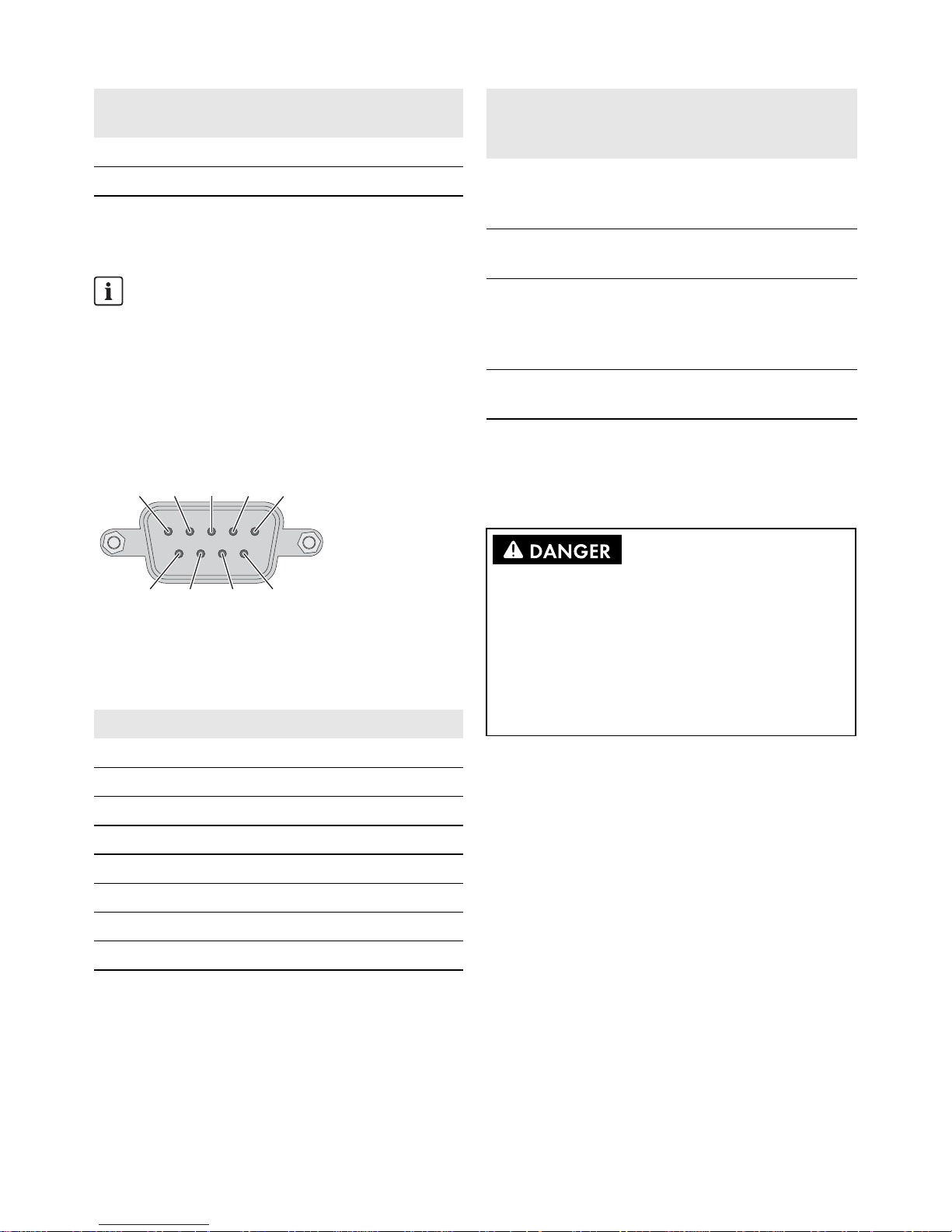
Pin assignment of the serial interface (RS485) at the Inverter
Manager:
Figure 5: Pin assignment of the serial interface
The I/O Box must be connected to port 2 of the Inverter
Manager. Termination for the RS485 interface is not
necessary.
Interfaces and Data of the Weather Station
Only one weather station can be connected to each Inverter
Manager. The weather station must be connected to port 1
of the Inverter Manager. A maximum of two temperature
sensors are supported.
The following data of the weather station are provided by
the Inverter Manager:
3.3.6 Connecting the
Inverter
Manager to the Voltage
Supply
Procedure:
To connect the Inverter Manager to the voltage supply,
perform the following actions in the specified order.
• Connect the grounding conductor to the
Inverter Manager.
• Connect the power supply unit.
Connecting the Grounding Conductor to the
Inverter Manager
Shielded ground: The shielded ground (also called
"protected ground") is located at the pin connector for the
electrical connection in the displayed view.
Procedure:
• Ground the Inverter Manager. For this purpose,
connect the grounding conductor to the grounding
screw of the Inverter Manager. Proper grounding and
the correct cable route help limit possible interference
emissions due to electromagnetic interferences (EMI).
7--- TRD(3)+
8--- TRD(3)-
Do not connect during operation
Do not connect the I/O Box or the weather station to
the Inverter Manager during operation. Errors might
occur that cannot be detected immediately.
• Disconnect the Inverter Manager from voltage
sources.
Pin Assignment
1 --2 --3 DataB(+)
4 DataA(-)
5GND
6 --7 --8 ---
Pin Assignment for
10/100 Mbps
Assignment for
1000 Mbps
3
2
1
4
5
9
8
7
6
Meteorological
data
SunSpec
Modbus
TCP
LCS-Tool /
FTP Push
Sunny
Portal
Ambient
temperature and
PV temperature
yes yes yes
Wind direction
and wind speed
yes yes yes
Horizontal
irradiation
yes yes If inclined
irradiation is
not
available
Inclined
irradiation
no yes yes
Danger to life due to electric shock from touching
an ungrounded product
Touching an ungrounded product can cause a lethal
electric shock.
• Ensure that the product is integrated into the existing
overvoltage protection.
• Ground the enclosure of the product.
Page 9

SMA Solar Technology AG 3 Inverter Manager
Installation Manual IMVIOBOX-IA-xx-16 9
Connecting the Power Supply Unit
SMA recommends using the top-hat rail power supply
available as an accessory (order number:
CLCON-PWRSUPPLY)* .
Procedure:
1. Mount the power supply unit (see the manufacturer
manual).
2. Connect the connection cable to the power supply unit
(see the manufacturer manual). Trim the unused
insulated conductors up to the cable sheath and write
down the conductor colors.
3. Connect the connection cable to the terminal block for
the voltage supply (9 VDC to 36 VDC). Make sure that
the shielded grounding conductor is connected with the
grounding terminal.
4. Plug the terminal block for the voltage supply with
connected power supply unit in the pin connector
"Power Input" of the Inverter Manager.
5. Connect the AC connection cable to the power supply
unit (see the manufacturer manual).
7. Connect the other end of the AC connection cable to
the voltage supply.
8. Connect the connection point to the utility grid.
☑ Once the Power LED is glowing green, the
Inverter Manager is ready for operation.
3.4 Ethernet Connection of the
Inverter Manager
LAN 1 (system network)
The IP address and the subnet mask are assigned to the
LAN 1 port of the Inverter Manager by an external DHCP
server.
An IP address can be manually assigned to LAN 1 Port of
the Inverter Manager.
LAN 2 (inverter network)
The IP address is assigned to the inverter by the Inverter
Manager.
Resetting the Inverter Manager to DHCP
• Press the power button three times in succession within
one second to reset the Inverter Manager to DHCP.
3.5 LED Signals of the
Inverter Manager
* Not available in all countries.
6.
Danger to life due to electric shock
Lethal voltages are present at the connection point of
the utility grid.
• Disconnect the connection point from voltage
sources and make sure it cannot be
reconnected.
GND
9 to 36 VDC
LED State Explanation
Power Glowing
green
The Inverter Manager is in
operation.
Off The Inverter Manager is not
in operation.
LAN Glowing
green
100 Mbps Ethernet mode
Glowing
yellow
1000 Mbps (gigabyte)
Ethernet mode
Off No activity or
10 Mbps Ethernet
Tx1, Tx2
(P1-P2)
Flashing
green
Data transmission via serial
ports P1-P2
Off No data transmission via
serial ports P1-P2
Rx1, Rx2
(P1-P2)
Flashing
green
Data reception via serial
ports P1-P2
Off No data reception via serial
ports P1-P2
Page 10

4 I/O Box SMA Solar Technology AG
10 IMVIOBOX-IA-xx-16 Installation Manual
3.6 Technical data
4 I/O Box
4.1 Scope of Delivery
Check the scope of delivery of each product for
completeness and any externally visible damage.
Contact your distributor if the scope of delivery is
incomplete or damaged.
The delivery may contain parts that are not required for the
installation.
Figure 6: Components included in scope of delivery of the I/O Box
Voltage supply
Input voltage 9 Vdc to 36 Vdc
Power consumption < 20 W
Maximum conductor
cross-section
1.3 mm² (16 AWG)
General data
Dimensions
(width x height x depth)
160 mm x 125 mm x
49 mm
(6.3 in x 4.9 in x 1.9 in)
Weight 940 g (2 lbs)
Mounting type Wall mounting or top-hat
rail
Operating temperature
range
-40°C to +75°C
-40°F to +167°F
Relative humidity,
non-condensing
5% to 95%
Approvals UL 508, UL 60950-1,
CSA C22.2 No.
60950-1-07, EN 60950-1,
CCC (GB9254,
GB17625.1), EN 55022,
Class A, EN 61000-3-2,
Class D, EN 61000-3-3,
EN 55024, FCC Part 15,
Subpart B, Class A
Interfaces
User interface LCS-Tool for PC via Ethernet
Interface to inverter LAN 2, Ethernet interface
(RJ45)
Interface to external
network
LAN 1, Ethernet interface
(RJ45)
Interface to I/O box
(optional)
RS485 (D-sub 9) /
SunSpec mode
Sensor interface for
SunSpec compatible
weather stations (optional)
RS485 (D-sub 9) /
SunSpec mode
Maximum cable length for
Ethernet connection
100 m (328 ft)
Maximum cable length for
RS485 cabling
1200 m (4000 ft)
System monitoring Sunny Portal, SunSpec
Modbus TCP
Active/reactive power
setpoint
Constant value, curve or
remotely controlled via
SunSpec Modbus TCP with
I/O Box
Supported baud rate for
operation of a weather
station
9600, 19200, 57600,
115200
Power supply unit (recommended)
Type designation CLCON-PWRSUPPLY*
Input 100 Vac to 240 Vac
Output 24 Vdc; 2.5 A
Ambient temperature -25°C to +70°C
Approvals CE, UL
* Not available in all countries.
Item Quantity Designation
A1 I/O Box
B1 CD
Interfaces
A
B
C
Page 11

SMA Solar Technology AG 4 I/O Box
Installation Manual IMVIOBOX-IA-xx-16 11
4.2 Mounting the I/O Box
4.2.1 Option 1: Wall Mounting
4.2.2 Option 2: Mounting on Top-Hat
Rail
4.3 Connection to the I/O Box
4.3.1 Overview
Figure 7: Overview of the connection to the I/O Box
4.3.2 Connecting the
Inverter
Manager
Pin assignment of the RS485 terminal
(see Section 3.3.5, page 8):
C 1 Quick reference guide for
installation
Damage to the products and cables due to moisture
The Inverter Manager and the I/O Box are not protected
against splash water. Consequently, moisture can
penetrate the device and damage the products and
cables.
• The Inverter Manager and the I/O Box must be
installed in a dry environment, e.g. indoors or in a
splash-proof enclosure (d egree of protec tio n: a t least
IP54 (NEMA 3R)).
Item Quantity Designation
1
2
1
2
3
Item Designation
A Digital inputs for connecting a signal source
(inputs DI0 to DI5 can be assigned; all
other inputs have no function)
B Maintain the default setting: X1 = 1,
X10 = 0
C Connection of the Inverter Manager
D Connection of the electricity supply
E Maintain the default setting: 1 = Dual,
2 = Initial
Do not connect during operation
Do not connect the I/O Box to the Inverter Manager
during operation. Errors might occur that cannot be
detected immediately.
• Disconnect the Inverter Manager from voltage
sources.
• Connect the I/O Box with the Inverter Manager.
• Reconnect the Inverter Manager to the voltage
supply.
1
2
3
4
5
6
7
8
9
0
1
2
3
4
5
6
7
8
9
0
1
2
3
4
5
6
7
8
9
0
1
2
3
4
5
6
7
8
9
0
D1+
D1-
GND
D2+
D2-
P1
P2
V+
V-
X10
X1
Dual
Run
Rep
Initial
COM0
DI0
DI1
DI2
DI3
DI4
DI5
DI6
DI7
COM1
DIO0
DIO1
DIO2
DIO3
GND
DIO4
DIO5
DIO6
DIO7
GND
A
C
D
COM0
DI0
DI1
DI2
DI3
DI4
DI5
GND
B
E
Page 12

4 I/O Box SMA Solar Technology AG
12 IMVIOBOX-IA-xx-16 Installation Manual
4.3.3 Connecting the Signal Source
Connection of a Signal Source with
Potential-Free Relay Contact
Connection of a Signal Source (10 V to 30 V)
with Digital Output Signals
4.3.4 Connecting the I/O Box to the
Voltage Supply
Connect the 12 Vdc to 36 Vdc connection line with the
terminal for the voltage supply. Connect the grounding of
the connection line to the "V" terminal and connect the
grounding pin (GND) if grounding is present.
4.3.5 LED Signals of the I/O Box
Pin Assignment
D2- --D2+ --GND GND
D1- DataA(-)
D1+ DataB(+)
(5) GND
(3) Data B (+)D1+
(4) Data A (−)/D1−
COM0
DI0
DI1
DI2
DI3
DI4
DI5
DI6
DI7
COM1
DIO0
DIO1
DIO2
DIO3
GND
DIO4
DIO5
DIO6
DIO7
GND
COM0
DI0
DI1
DI2
DI3
DI4
DI5
GND
Dry Contact:
closed: DI0 = on
open: DI0 = off
COM0
DI0
DI1
DI2
DI3
DI4
DI5
DI6
DI7
COM1
DIO0
DIO1
DIO2
DIO3
GND
DIO4
DIO5
DIO6
DIO7
GND
COM0
DI0
DI1
DI2
DI3
DI4
DI5
GND
Wet Contact:
0Vto3V=off
10Vto30V=on
U
U
10Vto30V
Pin Assignment
V- / V+ Voltage supply 24 Vdc (12 Vdc to 36 Vdc)
Diameter of the leads
For safety reasons, the leads for the electricity
supply must have a diameter of at least 2 mm².
LED State Explanation
Power Glowing
yellow
The I/O Box is in operation.
Off The I/O Box is not in operation.
Ready Glowing
green
The system is ready for
operation.
Green is
flashing once
per second
The "detect" function was
triggered.
Flashing
green every
0.5 seconds
Firmware is being updated.
Flashing
green
When the green LED is on for
five seconds and then goes off
for five seconds, it means that
the system is in "Safe Mode".
Off The system is not ready for
operation.
Port 1 Flashing
green
Data is being sent or received.
Port 2 Flashing
yellow
Data is being sent or received.
Page 13

SMA Solar Technology AG 4 I/O Box
Installation Manual IMVIOBOX-IA-xx-16 13
4.4 Technical data
System data
Electricity supply 24 Vdc nominal,
12 Vdc to 36 Vdc
Cabling I/O cable max. 25 mm²
(4 AWG)
Dimensions 27.8 mm x 124 mm x 84 mm
(1.09 in x 4.88 in x 3.31 in)
Weight < 200 g
Operating temperature
range
Standard module:
-10°C to +75°C
(14°F to 167°F)
Storage temperature -40°C to +85°C
(-40°F to 185°F)
Relative humidity,
non-condensing
5% to 95%
Operating altitude < 2000 m
Industry standards and
certifications
UL 508, CE, FCC Class A
Digital input
Sensor type Potential-free contact
(NPN or PNP); wet contact
I/O mode DI or event counter
Potential-free contact On = ground fault
Off = open
Wet contact (DI to COM) On = 10 Vdc to 30 Vdc
Off = 0 Vdc to 3 Vdc
Insulation voltage 3000 Vdc or 2000 Veff
Counter/Frequency 250 Hz, memory in off-state
Page 14

5 LCS tool SMA Solar Technology AG
14 IMVIOBOX-IA-xx-16 Installation Manual
5 LCS tool
The inverters and the Inverter Manager must be
commissioned via the local commissioning and service tool
(LCS-Tool). Commissioning is required before the inverters
are connected to the utility grid and start to feed-in power.
It is recommended to use the latest version of the LCS-Tool.
The LCS-Tool is available in the download area at
www.SMA-Solar.com.
The hardware requirements for the LCS-Tool are:
• PC with Windows
TM
7 and later
•1 GB HDD
• 2 GB RAM
The LCS-Tool must be installed on a local PC drive. The PC
must be connected to the LAN 1 port of the Inverter
Manager via a router (DHCP recommended).
Figure 8: Commissioning inverters via the LCS-Tool
5.1 Commissioning
1. Start up the LCS-Tool. The tool shows a list of all
identified Inverter Managers. It can take several
minutes until the LCS-Tool has identified all Inverter
Managers.
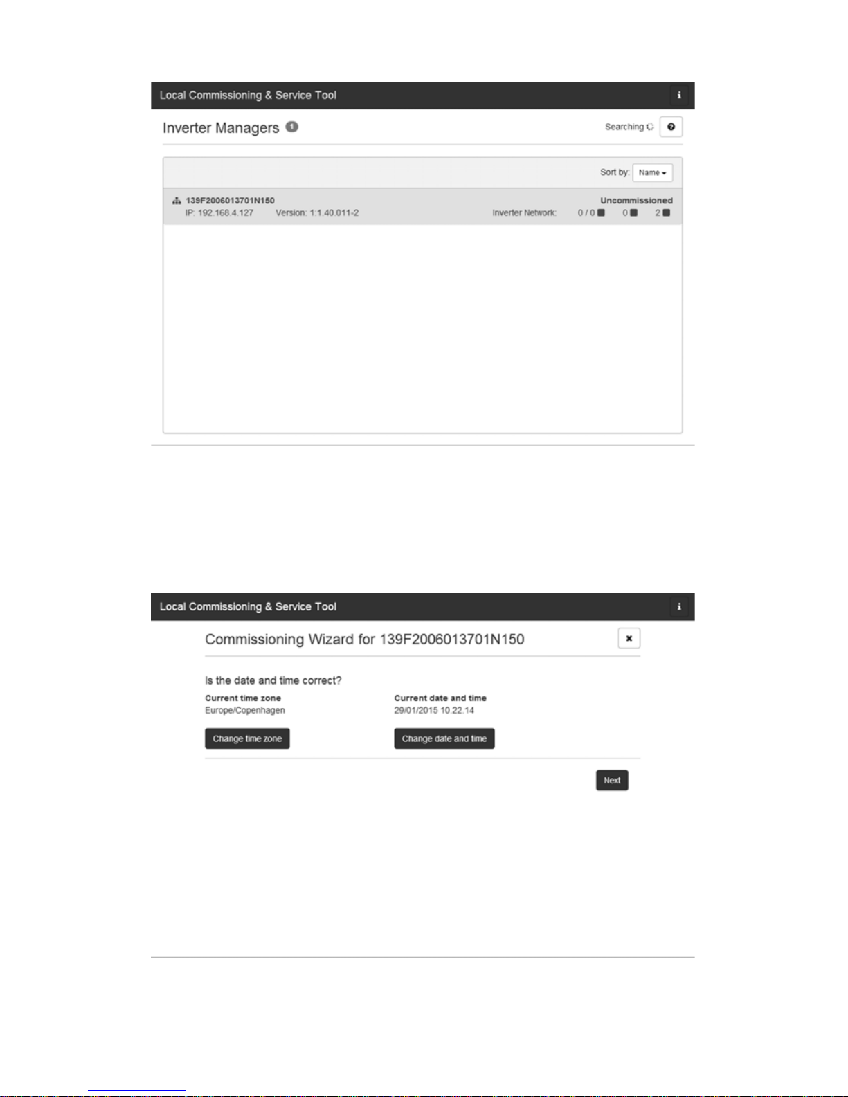
2. The screen now shows a list of all Inverter Managers
(see figure 9). To start the assistant, click on the Inverter
Manager to be configured. By clicking on the Inverter
Manager, the inverters found by the Inverter Manager
are displayed. Inverters that have not been
commissioned (no grid code assigned) are presented
with a blue square together with their software version.
INFORMATION
The LAN 1 port of the Inverter Manager must have
an IP address assigned by a DHCP server that is
connected to the LAN 1 port.
An IP address can be manually assigned to the
Inverter Manager.
It is important that the computer (on which the
LCS-Tool runs) is connected to the same IP subnet as
the Inverter Manager.
The Inverter Manager may not be assigned an IP
from the system network range 192.168.4.0/24.
The LAN 2 port is only intended for inverters and
battery storage systems.
ALCS tool
B Router (DHCP recommended)
C Inverter Manager
D Sunny Tripower 60 / Sunny Highpower 75
ELAN 1
FLAN 2
G Power Analyser UMG 604-PRO from Janitza
electronics GmbH
H Sunny Tripower Storage 60
I Battery
Page 15
SMA Solar Technology AG 5 LCS tool
Installation Manual IMVIOBOX-IA-xx-16 15
Figure 9: LCS-Tool - start screen
3. Assign a password for your user group when first
registering. The security status of your password is
displayed.
4. Verify that date and time are correct. If not, set date
and time and continue (see figure 10).
Figure 10: LCS-Tool - checking date and time
Page 16

5 LCS tool SMA Solar Technology AG
16 IMVIOBOX-IA-xx-16 Installation Manual
5. In case of battery storage systems, enter the battery
details. The details under Pre-Set Battery Limits serve as
additional safety limit for battery charging and
discharging (see the battery manufacturer's manual).
Figure 11: LCS-Tool - Battery details
6. Optionally, you can assign a name, location and
owner of the Inverter Manager (see figure 11).
Figure 12: LCS-Tool - PV system details
Page 17

SMA Solar Technology AG 5 LCS tool
Installation Manual IMVIOBOX-IA-xx-16 17
7. A list of the identified inverters of the selected Inverter
Manager is displayed.
Make sure that all inverters are present. It is possible to
continue the configuration of the listed inverters even if not
all inverters are detected. The undetected inverters can
always be configured later.
8. Select the desired country from the list of options
available for the inverters in the network (see figure
13).
9. Select the desired grid code from the list of options
available for the selected country. If necessary, load a
customer specific grid code by clicking the button
[Load] (see figure 13). The button [Create] is inactive
and cannot be used.
Figure 13: LCS-Tool - selecting the country and grid code
Page 18

5 LCS tool SMA Solar Technology AG
18 IMVIOBOX-IA-xx-16 Installation Manual
10. The LCS-Tool prompts for a confirmation of the selected
country and grid code. In case of battery storage
systems, the battery details are additionally shown.
A wrong configuration can be changed by clicking the
[Back] button and by changing the settings in the
previous window.
11. The system then applies the grid code selected on the
Inverter Manager to the detected inverters. Any
inverter added at a later stage automatically inherits
the same grid code. The application of only one grid
code is possible per Inverter Manager.
12. A green square identifies the commissioned inverters.
The inverters are only connected to the utility grid when
the [Start] command has been carried out from the bar
below the start menu (see figure 14).
Figure 14: LCS-Tool - list of all inverters connected to the Inverter
Manager
INFORMATION
It is essential to choose the correct grid code.
A modification after the first ten operating hours have
passed is only possible with a personal SMA Grid
Guard code.
The grid code parameters can be changed
subsequently with the LCS-Tool (see
section 5.2.7, page 28). Prerequisite is the use of the
latest version of the LCS-Tool.
Page 19

SMA Solar Technology AG 5 LCS tool
Installation Manual IMVIOBOX-IA-xx-16 19
13. If sufficient PV power is present and the grid code
conditions are met, the inverter starts the operation. For
battery storage systems, a successful battery start and
the fulfillment of the Grid-Code requirements is
necessary.
14. During commissioning it is possible to download a
commissioning report in the Reports menu. The report
contains information about inverter settings, including
actual disconnection values for each inverter. By
clicking the folder icon in the menu Reports, it is
possible to open a folder for commissioning reports
(incl. grid code information) (see 15).
Figure 15: LCS-Tool - commissioning report
Page 20

5 LCS tool SMA Solar Technology AG
20 IMVIOBOX-IA-xx-16 Installation Manual
5.2 Operation
5.2.1 Forgot Password
Figure 16: LCS-Tool - forgotten password?
If you have forgotten the password for the user interface,
you can log in with a Personal Unlocking Key (PUK). Each
user group has its own PUK.
Procedure:
1. Request a PUK (see "Application for ordering a PUK" at
www.SMA-Solar.com).
2. Open the LCS-Tool.
3. Select the user group User or Installer.
4. Enter the PUK instead of the password.
5. Call up the menu Setup.
6. Change the password of the desired user group under
Password.
7. Select [Save] to save the changes.
Page 21
SMA Solar Technology AG 5 LCS tool
Installation Manual IMVIOBOX-IA-xx-16 21
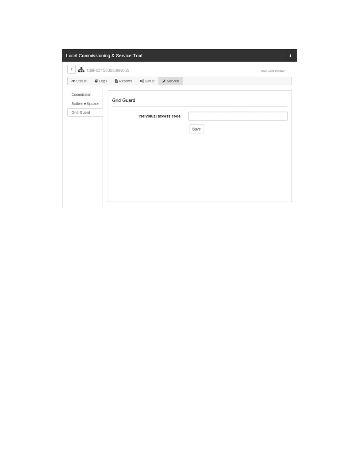
5.2.2 Changing the Grid Code
Figure 17: LCS-Tool - entering the SMA Grid Guard code
To reset the Inverter Manager after the first ten operating
hours and to select a new country data set, use your
SMA Grid Guard code under the user group Installer (see
certificate "Order form for the SMA Grid Guard code" at
www.SMA-Solar.com).
Procedure:
1. Open the LCS-Tool.
2. Log in as an Installer.
3. Call up the menu Service.
4. Enter your SMA Grid Guard code in the field
Individual access code under Grid Guard.
5. Select [Save] to save the changes.
☑ A new menu item General is available under the
menu Setup.
Page 22

5 LCS tool SMA Solar Technology AG
22 IMVIOBOX-IA-xx-16 Installation Manual
5.2.3 Updating the Firmware
Figure 18: LCS-Tool - manual firmware update
You can carry out the firmware update of the Inverter
Manager manually. It is recommended to use the latest
version of the LCS-Tool. The LCS-Tool is available in the
download area at www.SMA-Solar.com.
Procedure:
1. Open the LCS-Tool.
2. Log in as User or Installer.
3. Call up the menu Service.
4. Select the tab Inverter Manager under Software
Update.
5. Select [Start update] to carry out the update.
☑ The update is carried out now.
Damage to the products due to disruption of the
update procedure
If the connection between the Inverter Manager and the
computer is disrupted, a damage to the device may occur.
• Do not disconnect the connection between the
Inverter Manager and the computer.
• Do not disconnect the computer and
Inverter Manager from the electricity supply.
• Do not switch the computer to energy-saving mode.
Page 23

SMA Solar Technology AG 5 LCS tool
Installation Manual IMVIOBOX-IA-xx-16 23
5.2.4 Setting the System Fallback
Figure 19: LCS-Tool - setting the fallback parameter
A system fallback can be configured in the event of a
communication failure between the Inverter Manager and a
superior control unit (e.g. SCADA system or
Power Plant Controller). The superordinate system fallback
can only be configured via the LCS-Tool. To set the values
for a superordinate fallback, use your SMA Grid Guard
code under the user group Installer (see
section 5.2.2, page 21).
Procedure:
1. Open the LCS-Tool.
2. Log in as an Installer.
3. Call up the menu Setup.
4. Enter the respective values under Plant fallback.
5. Select [Save] to save the changes.
Page 24

5 LCS tool SMA Solar Technology AG
24 IMVIOBOX-IA-xx-16 Installation Manual
5.2.5 Setting Limited Export
Figure 20: LCS-Tool - setting Limited Export
With the Limited Export feature in connection with a
Modbus-capable energy meter, a maximum defined AC
output power can be made available at the grid-connection
point (see figure 22). The total nominal power of all
inverters connected to the Inverter Manager is taken into
account. At the grid-connection point, the inverter's
maximum output power is increased or decreased by the
amount of self-consumption.
The limitation at the grid-connection point is complied with,
while all connected loads can still be supplied with energy
from the inverters.
The maximum setpoint of the nominal PV system power can
be assigned with static or dynamic attributes:
• Assignment of static attributes:
Set the parameter Active Power (P_ref) for the active
power limitation in menu Inverter Parameter under
Protection settings > Support settings >
Immediate controls (see Section 5.2.7 “Changing of
Inverter Parameters”, page 28).
• Assignment of dynamic attributes:
In addition, the setpoint of the nominal PV system
power can be limited dynamically via I/O Box,
Modbus and direct marketer interface. If the value is set
dynamically, the parameter Active Power (P_ref) is
overwritten in the LCS-Tool. This applies to both the
regular feed-in operation and to the activated Limited
Export function. A load-dependent control is not
possible without an activated Limited Export function.
The inverters are then directly limited to the setpoint
(see figure 23).
Procedure:
1. Open the LCS-Tool.
2. Log in as an Installer.
3. Call up the menu Setup.
4. Enter the respective values under Limited Export.
5. Select [Save] to save the changes.
The parameters Meter IP-Address, Meter Modbus Port,
Meter Modbus Unit ID and the register Meter Power
Modbus are used for the configuration of the energy meter.
With zero export as a special case of Limited Export, the
feed-in operation into the utility grid can be completely
prevented. The parameter Safety Offset indicated as
percentage of nominal PV system power is a safety margin
to the maximum value of the output power set at the
grid-connection point.
This safety value is preset for safety reasons and due to
sudden load changes. Thus, a safety margin to the setpoint
is ensured. With the activation process, the setpoint is
reduced to the safety value. Thus, the feed-in power is
always less than the actual setpoint.
Page 25

SMA Solar Technology AG 5 LCS tool
Installation Manual IMVIOBOX-IA-xx-16 25
The parameter Meter Connection Timeout is the time in
seconds that is required to adjust the nominal PV system
power to 0 W when communication to the energy meter is
interrupted.
To acquire an overview of the current system values, open
the menu Status and select Overview (see figure 21).
Figure 21: LCS-Tool - Overview of current system values
Modbus control
To make this limitation permanent, set the desired
value in the Modbus register 40349.
To disconnect the inverter immediately from the utility
grid while the Limited Export function is running, set
the value "0" in the Modbus register 40348.
For further information on the Modbus interface see
technical information "SUNNY TRIPOWER 60 /
SUNNY HIGHPOWER PEAK1 - SunSpec®
Modbus® Interface" at www.SMA-Solar.com.
Page 26

5 LCS tool SMA Solar Technology AG
26 IMVIOBOX-IA-xx-16 Installation Manual
Figure 22: Feeding-in operation with Limited Export / Peak Load
Shaving
Figure 23: Feeding-in operation without Limited Export
A Inverters
B Inverter Manager
CLoads
D Utility grid
E Grid-connection point
F Sunny Tripower 60 / Sunny Highpower 75:
Energy meter
Sunny Tripower Storage 60:
Power analyzer UMG 604-PRO von Janitza
electronics GmbH
G Modbus TCP
HAC
Page 27

SMA Solar Technology AG 5 LCS tool
Installation Manual IMVIOBOX-IA-xx-16 27
5.2.6 Setting the Peak Load Shaving
Function
Figure 24: LCS-Tool - Setting the Peak Load Shaving function
With the Peak Load Shaving function in combination with
the Power Analyser UMG 604-PRO from Janitza electronics
GmbH, the behavior of the Sunny Tripower Storage 60 on
the power exchange at the grid-connection point can be
optimized (see Figure 22). With the "Peak Load Shaving"
function, certain grid-exchange power outputs to which the
Sunny Tripower Storage 60 is adjusted depending on its
power and battery capacity available can be set. The
acquisition of active power at the grid-connection point is
systematically limited to a maximum value (Discharge
Setpoint/Consumption Limit). This maximum value is
given as upper limit for the grid reference power in the
LCS-Tool. The battery is discharged above this maximum
value in a controlled manner. Thus, the maximum value is
retained as long as the battery capacity allows it.
The battery is charged when the value is below the minimum
value set in the LCS-Tool (Charge Setpoint/Feed-in
Limit). In conjunction with a PV system, this value specifies
the threshold for increased self-consumption.
Procedure:
1. Open the LCS-Tool.
2. Log in as an Installer.
3. Call up the menu Setup.
4. In the menu Limited Export, the function Peak Load
Shaving is activated.
5. Under Peak Load Shaving, enter the respective
values for Discharge Setpoint/Consumption Limit
and Charge Setpoint/Feed-in Limit in kW.
6. Select [Save] to save the changes.
Page 28

5 LCS tool SMA Solar Technology AG
28 IMVIOBOX-IA-xx-16 Installation Manual
5.2.7 Changing of Inverter
Parameters
Figure 25: LCS-Tool - changing of inverter parameters
All inverter parameter are Grid Guard protected and
require the Grid Guard code for changes. To change the
inverter settings, use your SMA Grid Guard code under the
user group Installer (see section 5.2.2, page 21).
Procedure:
1. Open the LCS-Tool.
2. Log in as an Installer.
3. Call up the menu Setup.
4. Enter the respective values under Inverter
Parameter.
5. Select [Save] to save the changes.
Input values for Peak Load Shaving
The input value for Discharge Setpoint/
Consumption Limit is interpreted by the Inverter
Manager as a positive value and the one for Charge
Setpoint/Feed-in Limit as a negative value. If the
Inverter Manager, for example, has to limit the grid
reference power to +50 kW and charge the battery
below a grid reference power of +10 kW, the value
50 must be entered for Discharge Setpoint/
Consumption Limit and the value -10 for Charge
Setpoint/Feed-in Limit.
If the value for Discharge Setpoint/Consumption
Limit and the value for Charge Setpoint/Feed-in
Limit is set to 0, this corresponds to the classical
increased self-consumption of PV power without the
shaving of peak loads.
FNN note
In Germany, according to FNN note "Connecting
and operating storage units in low voltage networks"
(October 2016), systems eligible under the FIT
scheme in accordance with EEG and KWKG are not
allowed to feed energy from storage units into the
utility grid. To ensure this, the input value for
Discharge Setpoint/Consumption Limit is not
allowed to be negative.
Page 29

SMA Solar Technology AG 5 LCS tool
Installation Manual IMVIOBOX-IA-xx-16 29
Deactivating/Activating the inverter
parameters
To activate and deactivate a parameter, double-click on the
parameter using the left mouse button.
When the parameters are activated, the input fields and
buttons are enabled. Inactive parameters are marked with
disable.
Fi gure 26: LC S-T ool - dea cti vating/ act ivating the inverte r pa rameters
Page 30

5 LCS tool SMA Solar Technology AG
30 IMVIOBOX-IA-xx-16 Installation Manual
Changing signs on power factor parameters
To change signs on power factor parameters, click on the
sign using the left mouse button.
Figure 27: LCS-Tool - changing signs
Setting the I/O Box Parameters
To enter the parameters in the sub-menu I/O Box, click on
the input fields using the right mouse buttons.
Figure 28: LCS-Tool - setting the I/O Box parameter
Page 31

SMA Solar Technology AG 5 LCS tool
Installation Manual IMVIOBOX-IA-xx-16 31
5.2.8 Logs
Information on events, performance data, parameter
specifications and changed inverter parameters can be
found in the menu Logs.
Figure 29: LCS-Tool - logs
Page 32

5 LCS tool SMA Solar Technology AG
32 IMVIOBOX-IA-xx-16 Installation Manual
Page 33

IMVIOBOX-IA-xx-16 | Version 1.6 DEUTSCH
1 Hinweise zu diesem
Dokument
1.1Gültigkeitsbereich
Dieses Dokument gilt für den SMA Inverter Manager, die
SMA Digital I/O Box und das LCS-Tool.
1.2Zielgruppe
Die in diesem Dokument beschriebenen Tätigkeiten dürfen
nur Fachkräfte durchführen. Die Fachkräfte müssen über
folgende Qualifikation verfügen:
• Ausbildung für die Installation und Inbetriebnahme von
elektrischen Geräten
• Schulung im Umgang mit Gefahren und Risiken bei der
Installation und Bedienung elektrischer Geräte und
Anlagen
• Ausbildung für die Installation und Konfiguration von
IT-Systemen
• Kenntnis über Funktionsweise und Betrieb eines
Wechselrichters
• Kenntnis der einschlägigen Gesetze, Normen und
Richtlinien
• Kenntnis und Beachtung dieses Dokuments mit allen
Sicherheits- und Warnhinweisen
1.3Symbole
1.4Nomenklatur
Symbol Erklärung
(&'")3
Warnhinweis, dessen
Nichtbeachtung unmittelbar
zum Tod oder zu schwerer
Verletzung führt
Warnhinweis, dessen
Nichtbeachtung zum Tod oder
zu schwerer Verletzung führen
kann
Warnhinweis, dessen
Nichtbeachtung zu einer
leichten oder mittleren
Verletzung führen kann
Warnhinweis, dessen
Nichtbeachtung zu
Sachschäden führen kann
Information, die für ein
bestimmtes Thema oder Ziel
wichtig, aber nicht
sicherheitsrelevant ist
☐ Voraussetzung, die für ein
bestimmtes Ziel gegeben sein
muss
☑ Erwünschtes Ergebnis
✖ Möglicherweise auftretendes
Problem
Vollständige Benennung Benennung in diesem
Dokument
SMA Inverter Manager Inverter Manager
SMA Digital I/O Box I/O Box
Local Commissioning and
Service Tool (lokales
Inbetriebnahme- und
Service-Tool)
LCS-Tool
Sunny Tripower 60, Sunny
Highpower Peak1, Sunny
Tripower Storage 60
Wechselrichter
SMA Solar Technology AG SMA
SMA Solar Technology
America LLC
SMA Solar Technology
Canada Inc.
Symbol Erklärung
Installationsanleitung
SMA INVERTER MANAGER /
SMA DIGITAL I/O BOX /
LCS-TOOL
Page 34

2 Sicherheit SMA Solar Technology AG
34 IMVIOBOX-IA-xx-16 Installationsanleitung
2Sicherheit
2.1Bestimmungsgemäße
Verwendung
Der Inverter Manager ist ein Gerät zur Überwachung und
Steuerung von bis zu 42 Sunny Tripower 60 oder Sunny
Highpower 75 oder bis zu 20 Sunny Tripower Storage 60
mit Batteriespeichersystemen in dezentralen PV-Anlagen.
Die I/O Box ist eine Funktionsschnittstelle für 1 Inverter
Manager. Die I/O Box empfängt Befehle für die
Netzsystemdienstleistungen über digitale Signale und
sendet die Vorgaben an den Inverter Manager.
Der Inverter Manager empfängt die Vorgaben von der
I/O Box und steuert entsprechend alle Wechselrichter in
der PV-Anlage. Der Inverter Manager und die I/O Box
dürfen nur im Innenbereich eingesetzt und ausschließlich mit
Sunny Tripower 60, Sunny Tripower Storage 60 und Sunny
Highpower Peak1 betrieben werden.
Das LCS-Tool ist für die Inbetriebnahme und den Service der
Wechselrichter über den Inverter Manager erforderlich.
Das LCS-Tool dient als primäre Benutzeroberfläche für die
PV-Anlage und das Batteriespeichersystem.
Setzen Sie das Produkt ausschließlich nach den Angaben
der beigefügten Dokumentationen und gemäß den vor Ort
gültigen Normen und Richtlinien ein. Ein anderer Einsatz
kann zu Personen- oder Sachschäden führen. Aus
Sicherheitsgründen ist es untersagt, das Produkt zu
verändern oder Bauteile einzubauen, die nicht ausdrücklich
von SMA für das Produkt empfohlen oder vertrieben
werden. Unerlaubte Veränderungen oder Umbauten lassen
die Gewährleistungsansprüche und die Betriebserlaubnis
erlöschen. Je de andere Verwendung des Produkts als in der
bestimmungsgemäßen Verwendung beschrieben gilt als
nicht bestimmungsgemäß.
Das Typenschild muss dauerhaft am Produkt angebracht
sein. Die beigefügten Dokumentationen sind Bestandteil des
Produkts.
3Inverter Manager
3.1Lieferumfang
Prüfen Sie den Lieferumfang jedes Produkts auf
Vollständigkeit und äußerlich sichtbare Beschädigungen.
Setzen Sie sich bei unvollständigem Lieferumfang oder
Beschädigungen mit Ihrem Fachhändler in Verbindung.
Im Lieferumfang können weitere Bestandteile enthalten sein,
die nicht für die Installation benötigt werden.
Abbildung1:Bestandteile des Lieferumfangs des Inverter Managers
Position Anzahl Bezeichnung
A 1 Inverter Manager
B 2 Halterungen für Wandmontage
C 1 Halterung für Montage auf
Hutschiene (35 mm DIN rail)
D 1 Anschluss für Stromversorgung
E2Aderendhülsen
F 1 Klemmleiste für Stromversorgung
G 2 Klemmleisten für seriellen
Anschluss
H 4 Schrauben für Wand- und
Hutschienenmontage
I 1 Installationsanleitung
Page 35

SMA Solar Technology AG 3 Inverter Manager
Installationsanleitung IMVIOBOX-IA-xx-16 35
3.2Inverter Manager montieren
3.2.1Variante 1: Montage an Wand
3.2.2Variante 2: Montage an
Hutschiene
Beschädigung der Produkte und Leitungen durch
Feuchtigkeit
Der Inverter Manager und die I/O Box sind nicht
spritzwassergeschützt. Dadurch kann Feuchtigkeit
eindringen und die Produkte und Leitungen beschädigen.
• Der Inverter Manager und die I/O Box müssen in
trockener Umgebung, z. B. im Innenraum oder in
einem spritzwassergeschütztem Gehäuse (Schutzart:
mindestens IP54 (NEMA 3R)) installiert werden.
Page 36

3 Inverter Manager SMA Solar Technology AG
36 IMVIOBOX-IA-xx-16 Installationsanleitung
3.3Anschluss an den Inverter
Manager
3.3.1Sicherheitshinweis
3.3.2Verschaltungsübersicht Sunny
Tripower 60 / Sunny Highpower 75
Abbildung2:Verschaltungsübersicht Sunny Tripower 60 /
Sunny Highpower 75
(&'")3
Lebensgefahr durch Stromschlag
An der Anschluss-Stelle des öffentlichen Stromnetzes
liegen lebensgefährliche Spannungen an.
• Die Anschluss-Stelle freischalten und sicherstellen,
dass die Anschluss-Stelle frei von Spannung ist.
Position Bezeichnung
A Sunny Tripower 60 / Sunny Highpower 75
BPC mit LCS-Tool
CRouter
D SunSpec Alliance kompatible Wetterstation
(optional)
E I/O Box (optional)
FInverter Manager
Position Bezeichnung
Page 37

SMA Solar Technology AG 3 Inverter Manager
Installationsanleitung IMVIOBOX-IA-xx-16 37
3.3.3Verschaltungsübersicht Sunny
Tripower Storage 60
Abbildung3:Verschaltungsübersicht Sunny Tripower Storage 60
3.3.4Wechselrichter und Router über
Ethernet anschließen
Pin-Belegung der Netzwerkbuchsen (LAN 1 und LAN 2):
Abbildung4:Pin-Belegung der Netzwerkbuchsen
Position Bezeichnung
A Batterie
B Sunny Tripower Storage 60
CPC mit LCS-Tool
D Power Analyser UMG 604-PRO von
Janitza electronics GmbH
ERouter
F SunSpec Alliance kompatible Wetterstation
(optional)
G I/O Box (optional)
H Inverter Manager
Pin Belegung bei
10/100 Mbps
Belegung bei
1.000 Mbps
1ETx+ TRD(0)+
2ETx- TRD(0)3 ERx+ TRD(1)+
4 --- TRD(2)+
5 --- TRD(2)6 ERx- TRD(1)-
81
81
Page 38

3 Inverter Manager SMA Solar Technology AG
38 IMVIOBOX-IA-xx-16 Installationsanleitung
3.3.5I/O Box und Wetterstation
anschließen (optional)
Pin-Belegung der seriellen Schnittstelle (RS485) am Inverter
Manager:
Abbildung5:Pin-Belegung der seriellen Schnittstelle
Die I/O Box wird an Port 2 des Inverter Managers
angeschlossen. Eine Terminierung für die
RS485-Schnittstelle ist nicht notwendig.
Schnittstellen und Daten der Wetterstation
An jedem Inverter Manager kann nur 1 Wetterstation
angeschlossen werden. Die Wetterstation wird an Port 1
des Inverter Managers angeschlossen. Dabei werden
maximal 2 Temperatursensoren unterstützt.
Folgende Daten der Wetterstation werden vom Inverter
Manager bereitgestellt:
3.3.6Inverter Manager an
Spannungsversorgung anschließen
Vorgehen:
Um den Inverter Manager an die Spannungsversorgung
anzuschließen, führen Sie die folgenden Handlungen in der
vorgegebenen Reihenfolge aus.
• Erdungsleitung an Inverter Manager anschließen.
•Netzteil anschließen.
Erdungsleitung an Inverter Manager
anschließen
SG: Der Schutzerdungskontakt (Shielded Ground, SG;
auch als Protected Ground bezeichnet) befindet sich in der
dargestellten Ansicht oben an der Buchse für den
Stromanschluss.
7--- TRD(3)+
8--- TRD(3)-
Nicht im laufenden Betrieb verbinden
Schließen Sie die I/O Box oder die Wetterstation
nicht im laufenden Betrieb an den Inverter Manager
an. Es könnten Fehler auftreten, die nicht sofort
erkannt werden.
• Den Inverter Manager spannungsfrei schalten.
Pin Belegung
1 --2 --3 DataB(+)
4 DataA(-)
5GND
6 --7 --8 ---
Pin Belegung bei
10/100 Mbps
Belegung bei
1.000 Mbps
3
2
1
4
5
9
8
7
6
Wetterdaten SunSpec
Modbus
TCP
LCS-Tool /
FTP-Push
Sunny
Portal
Umgebungs- und
PV-Temperatur
ja ja ja
Windrichtung und
-geschwindigkeit
ja ja ja
Horizontale
Einstrahlung
ja ja Wenn
geneigte
Einstrahlung
nicht
vorhanden
Geneigte
Einstrahlung
nein ja ja
(&'")3
Lebensgefahr durch Stromschlag beim Berühren
eines nicht geerdeten Produkts
Durch das Berühren eines nicht geerdeten Produkts kann
ein lebensgefährlicher Stromschlag entstehen.
• Sicherstellen, dass das Produkt in den bestehenden
Überspannungsschutz integriert ist.
• Das Gehäuse des Produkts erden.
Page 39

SMA Solar Technology AG 3 Inverter Manager
Installationsanleitung IMVIOBOX-IA-xx-16 39
Vorgehen:
• Den Inverter Manager erden. Dazu den Erdungsleiter
an der Erdungsschraube des Inverter Managers
anschließen. Eine ordentliche Erdung und der korrekte
Kabelverlauf tragen dazu bei, mögliche
Störaussendungen aufgrund elektromagnetischer
Interferenzen (EMI) einzuschränken.
Netzteil anschließen
SMA empfiehlt die Verwendung des als Zubehör
erhältlichen Hutschienennetzteils (Bestellnummer:
CLCON-PWRSUPPLY)* .
Vorgehen:
1. Das Netzteil montieren (siehe Anleitung des
Herstellers).
2. Das Anschlusskabel an das Netzteil anschließen (siehe
Anleitung des Herstellers). Dabei die nicht benötigten
Adern bis zum Kabelmantel kürzen und die Aderfarben
notieren.
3. Das Anschlusskabel an die Klemmleiste für
Spannungsversorgung (9 Vdc bis 36 Vdc)
anschließen. Beachten Sie, dass der abgeschirmte
Erdleiter mit der Erdungsklemme verbunden ist.
4. Klemmleiste für Spannungsversorgung mit
angeschlossenem Netzteil in die Buchse „Power Input“
des Inverter Managers stecken.
5. Das AC-Anschlusskabel an das Netzteil anschließen
(siehe Anleitung des Herstellers).
7. Das andere Ende des AC-Anschlusskabels an die
Spannungsversorgung anschließen.
8. Die Anschluss-Stelle mit dem öffentlichen Stromnetz
verbinden.
☑ Sobald die Power-LED grün leuchtet ist der Inverter
Manager betriebsbereit.
3.4Ethernet-Verbindung des
Inverter Managers
LAN 1 (Anlagennetzwerk)
Die IP-Adresse und die Subnetzmaske werden dem LAN 1
Port des Inverter Manager durch einen externen
DHCP-Server zugewiesen.
Dem LAN 1 Port des Inverter Manager kann auch manuell
eine IP-Adresse zugewiesen werden.
LAN 2 (Wechselrichternetzwerk)
Die IP-Adresse wird dem Wechselrichter vom Inverter
Manager zugewiesen.
Inverter Manager auf DHCP zurücksetzen
• Um den Inverter Manager auf DHCP zurückzusetzen,
die Power-Taste 3 mal innerhalb 1 Sekunde drücken.
3.5LED-Signale des Inverter
Managers
* Nicht in allen Ländern verfügbar.
6.
(&'")3
Lebensgefahr durch Stromschlag
An der Anschluss-Stelle des öffentlichen Stromnetzes
liegen lebensgefährliche Spannungen an.
• Die Anschluss-Stelle freischalten und gegen
Wiedereinschalten sichern.
GND
9 to 36 VDC
LED Zustand Erklärung
Power Grün
leuchtet
Der Inverter Manager ist in
Betrieb.
Aus Der Inverter Manager ist
nicht in Betrieb.
LAN Grün
leuchtet
100 Mbps Ethernet-Modus
Gelb
leuchtet
1000 Mbps (Gigabit)
Ethernet-Modus
Aus Keine Aktivität oder
10 Mbps Ethernet
Tx1, Tx2
(P1-P2)
Grün blinkt Datenübertragung über
serielle Ports P1-P2
Aus Keine Datenübertragung
über serielle Ports P1-P2
Rx1, Rx2
(P1-P2)
Grün blinkt Datenempfang durch serielle
Ports P1-P2
Aus Kein Datenempfang durch
serielle Ports P1-P2
Page 40

4 I/O Box SMA Solar Technology AG
40 IMVIOBOX-IA-xx-16 Installationsanleitung
3.6Technische Daten
4I/O Box
4.1Lieferumfang
Prüfen Sie den Lieferumfang jedes Produkts auf
Vollständigkeit und äußerlich sichtbare Beschädigungen.
Setzen Sie sich bei unvollständigem Lieferumfang oder
Beschädigungen mit Ihrem Fachhändler in Verbindung.
Im Lieferumfang können weitere Bestandteile enthalten sein,
die nicht für die Installation benötigt werden.
Abbildung6:Bestandteile des Lieferumfangs der I/O Box
Spannungsversorgung
Eingangsspannung 9 Vdc bis 36 Vdc
Leistungsaufnahme < 20 W
Maximaler Leiterquerschnitt 1,3 mm² (16 AWG)
Allgemeine Daten
Maße (Breite x Höhe x
Tiefe)
160 mm x 125 mm x
49 mm
(6,3 in x 4,9 in x 1,9 in)
Gewicht 940 g (2 lbs)
Montageart Wandmontage oder
Hutschiene
Betriebstemperaturbereich -40 °C bis +75 °C
(-40 °F bis +167 °F)
Relative Luftfeuchte, nicht
kondensierend
5 % bis 95 %
Zulassungen UL 508, UL 60950-1,
CSA C22.2 No.
60950-1-07, EN 60950-1,
CCC (GB9254,
GB17625.1), EN 55022,
Class A, EN 61000-3-2,
Class D, EN 61000-3-3,
EN 55024, FCC Part 15,
Subpart B, Class A
Schnittstellen
Benutzerschnittstelle LCS-Tool für PC über
Ethernet
Schnittstelle zum
Wechselrichter
LAN 2,
Ethernet-Schnittstelle (RJ45)
Schnittstelle zum externen
Netzwerk
LAN 1,
Ethernet-Schnittstelle (RJ45)
Schnittstelle zur I/O Box
(optional)
RS485 (D-Sub 9) /
SunSpec Modus
Sensorschnittstelle für
SunSpec kompatible
Wetterstationen (optional)
RS485 (D-Sub 9) /
SunSpec Modus
Maximale Kabellänge für
Ethernet-Verbindung
100 m (328 ft)
Maximale Kabellänge für
RS485-Verkabelung
1200 m (4000 ft)
Anlagenüberwachung Sunny Portal,
SunSpec Modbus TCP
Wirk- und
Blindleistungsvorgabe
Konstanter Wert, Kurve
oder fernsteuerbar über
SunSpec Modbus TCP mit
I/O Box
Unterstützte Baudraten für
Betrieb einer Wetterstation
9600, 19200, 57600,
115200
Netzteil (empfohlen)
Typenbezeichnung CLCON-PWRSUPPLY*
Eingang 100 Vac bis 240 Vac
Ausgang 24 Vdc; 2,5 A
Umgebungstemperatur -25 °C bis +70 °C
Zulassungen CE, UL
* Nicht in allen Ländern verfügbar.
Position Anzahl Bezeichnung
A1I/O Box
B1CD
C 1 Schnelleinstieg zur Installation
Schnittstellen
A
B
C
Page 41

SMA Solar Technology AG 4 I/O Box
Installationsanleitung IMVIOBOX-IA-xx-16 41
4.2I/O Box montieren
4.2.1Variante 1: Montage an Wand
4.2.2Variante 2: Montage an
Hutschiene
4.3Anschluss an die I/O Box
4.3.1Übersicht
Abbildung7:Übersicht Anschluss I/O Box
4.3.2Inverter Manager anschließen
Beschädigung der Produkte und Leitungen durch
Feuchtigkeit
Der Inverter Manager und die I/O Box sind nicht
spritzwassergeschützt. Dadurch kann Feuchtigkeit
eindringen und die Produkte und Leitungen beschädigen.
• Der Inverter Manager und die I/O Box müssen in
trockener Umgebung, z. B. im Innenraum oder in
einem spritzwassergeschütztem Gehäuse (Schutzart:
mindestens IP54 (NEMA 3R)) installiert werden.
1
2
1
2
3
Position Bezeichnung
A Digitale Eingänge für den Anschluss einer
Signalquelle (Eingänge DI0 bis DI5 können
belegt werden, alle anderen Eingänge sind
ohne Funktion)
B Werkseinstellung beibehalten: X1 = 1,
X10 = 0
C Anschluss des Inverter Managers
D Anschluss der Stromversorgung
E Werkseinstellung beibehalten: 1 = Dual,
2 = Initial
Nicht im laufenden Betrieb verbinden
Schließen Sie die I/O Box nicht im laufenden Betrieb
an den Inverter Manager an. Es könnten Fehler
auftreten, die nicht sofort erkannt werden.
• Den Inverter Manager spannungsfrei schalten.
• Die I/O Box mit dem Inverter Manager
verbinden.
• Den Inverter Manager wieder an die
Spannungsversorgung anschließen.
1
2
3
4
5
6
7
8
9
0
1
2
3
4
5
6
7
8
9
0
1
2
3
4
5
6
7
8
9
0
1
2
3
4
5
6
7
8
9
0
D1+
D1-
GND
D2+
D2-
P1
P2
V+
V-
X10
X1
Dual
Run
Rep
Initial
COM0
DI0
DI1
DI2
DI3
DI4
DI5
DI6
DI7
COM1
DIO0
DIO1
DIO2
DIO3
GND
DIO4
DIO5
DIO6
DIO7
GND
A
C
D
COM0
DI0
DI1
DI2
DI3
DI4
DI5
GND
B
E
Page 42

4 I/O Box SMA Solar Technology AG
42 IMVIOBOX-IA-xx-16 Installationsanleitung
Pin-Belegung der RS485-Anschlussklemme
(siehe Kapitel 3.3.5,Seite38):
4.3.3Signalquelle anschließen
Anschluss einer Signalquelle mit
potenzialfreiem Relais-Kontakt
Anschluss einer Signalquelle (10 V bis 30 V) mit
digitalen Ausgangssignalen
4.3.4I/O Box an
Spannungsversorgung anschließen
Verbinden Sie die 12 Vdc bis 36 Vdc Anschlussleitung mit
der Anschlussklemme für die Spannungsversorgung.
Schließen Sie die Erdung der Anschlussleitung an die
Klemme „V-“ an und verbinden Sie den Erdungspin (GND)
wenn eine Erdung vorhanden ist.
4.3.5LED-Signale der I/O Box
Pin Belegung
D2- --D2+ --GND GND
D1- DataA(-)
D1+ DataB(+)
(5) GND
(3) Data B (+)D1+
(4) Data A (−)/D1−
Pin Belegung
V- / V+ Spannungsversorgung 24 Vdc
(12 Vdc bis 36 Vdc)
Durchmesser der Anschlussdrähte
Aus Sicherheitsgründen sollten die Anschlussdrähte
für die Stromversorgung einen Durchmesser von
mindestens 2 mm² aufweisen.
LED Zustand Erklärung
Power Gelb leuchtet Die I/O Box ist in Betrieb.
Aus Die I/O Box ist nicht in Betrieb.
Ready Grün leuchtet Das System ist betriebsbereit.
Grün blinkt
1-mal pro
Sekunde
Die Funktion „Auffinden“
wurde ausgelöst.
Grün blinkt
alle 0,5
Sekunden
Die Firmware wird aktualisiert.
Grün blinkt Wenn die grüne LED 5
Sekunden leuchtet und danach
für 5 Sekunden erlischt
bedeutet dass, dass das System
sich im „Safe Mode“ befindet.
Aus Das System ist nicht
betriebsbereit.
Port 1 Grün blinkt Daten werden gesendet oder
empfangen.
Page 43

SMA Solar Technology AG 4 I/O Box
Installationsanleitung IMVIOBOX-IA-xx-16 43
4.4Technische Daten
Port 2 Gelb blinkt Daten werden gesendet oder
empfangen.
Systemdaten
Stromversorgung 24 Vdc nominal,
12 Vdc bis 36 Vdc
Verkabelung I/O Kabel max. 25 mm²
(4 AWG)
Abmessungen 27,8 mm x 124 mm x 84 mm
(1.09 x 4.88 x 3.31 in)
Gewicht < 200 g
Betriebstemperaturbereich Standard Modul:
-10 °C bis +75 °C
(14 °F bis 167 °F)
Lagerungstemperatur -40 °C bis +85 °C
(-40 °F bis 185 °F)
Relative Luftfeuchtigkeit,
nicht kondensierend
5 % bis 95 %
Betriebshöhe < 2000 m
Standards und
Zertifizierungen
UL 508, CE, FCC Class A
Digitaler Eingang
Sensortyp Potenzialfreier Kontakt
(NPN oder PNP),
Potenzialbehafteter Kontakt
I/O Mode DI oder Ereigniszähler
Potenzialfreier Kontakt Ein = Erdschluss
Aus = Open
Potenzialbehafteter Kontakt
(DI zu COM)
Ein = 10 Vdc bis 30 Vdc
Aus = 0 Vdc bis 3 Vdc
Isolationsspannung 3000 Vdc oder 2000 Veff
Counter/Frequenz 250 Hz, Speicher im
ausgeschalteten Zustand
LED Zustand Erklärung
Page 44

5 LCS-Tool SMA Solar Technology AG
44 IMVIOBOX-IA-xx-16 Installationsanleitung
5LCS-Tool
Die Wechselrichter und der Inverter Manager müssen über
das lokale Inbetriebnahme- und Service-Tool (LCS-Tool) in
Betrieb genommen werden. Die Inbetriebnahme ist
erforderlich, bevor die Wechselrichter an das AC-Netz
angeschlossen werden und einspeisen.
Es wird empfohlen, die aktuellste Version des LCS-Tools zu
verwenden. Das LCS-Tool ist im Downloadbereich unter
www.SMA-Solar.com verfügbar.
Hardware Anforderungen für das LCS-Tool:
•PC mit Windows
TM
7 oder neuer
•1 GB HDD
• 2 GB RAM
Das LCS-Tool muss auf einem lokalen PC-Laufwerk installiert
werden. Der PC muss über einen Router (DHCP empfohlen)
an den LAN 1 Port des Inverter Managers angeschlossen
werden.
Abbildung8:Inbetriebnahme von Wechselrichtern über LCS-Tool
5.1Erstinbetriebnahme
1. Starten Sie das LCS-Tool. Das Tool zeigt eine Liste aller
identifizierten Inverter Manager. Es kann mehrere
Minuten dauern, bis das LCS-Tool alle Inverter
Manager identifiziert hat.
2. Der Bildschirm zeigt jetzt eine Liste aller Inverter
Manager (siehe Abbildung 9). Zum Start des
Assistenten klicken Sie den zu konfigurierenden
Inverter Manager an. Durch Anklicken des Inverter
Managers werden die vom Inverter Manager
gefundenen Wechselrichter angezeigt. Nicht in Betrieb
genommene Wechselrichter (kein zugewiesener
Grid-Code) werden mit einem blauen Quadrat
zusammen mit ihrer Software-Version aufgeführt.
HINWEIS
Dem LAN 1 Port des Inverter Managers muss vom
DHCP-Server, der an den LAN 1 Port angeschlossen
ist, eine IP-Adresse zugewiesen werden.
Dem Inverter Manager kann auch manuell eine
IP-Adresse zugewiesen werden.
Es ist wichtig, dass der PC, auf dem das LCS-Tool
läuft, an das gleiche IP-Subnetz angeschlossen ist wie
der Inverter Manager.
Dem Inverter Manager darf keine IP aus dem
Anlagennetzwerkbereich 192.168.4.0/24
zugewiesen werden.
Der LAN 2 Port ist ausschließlich für die
Wechselrichter und Batteriespeichersysteme
bestimmt.
ALCS-Tool
B Router (DHCP empfohlen)
C Inverter Manager
D Sunny Tripower 60 / Sunny Highpower 75
ELAN 1
FLAN 2
G Power Analyser UMG 604-PRO von Janitza
electronics GmbH
H Sunny Tripower Storage 60
I Batterie
Page 45

SMA Solar Technology AG 5 LCS-Tool
Installationsanleitung IMVIOBOX-IA-xx-16 45
Abbildung9:LCS-Tool - Startbildschirm
3. Vergeben Sie bei der Erstanmeldung ein Passwort für
Ihre Benutzergruppe. Der Sicherheitsstatus Ihres
Passworts wird Ihnen angezeigt.
4. Überprüfen, ob Datum und Uhrzeit richtig sind. Falls
nicht, Datum und Uhrzeit einstellen und fortfahren
(siehe Abbildung 10).
Abbildung10:LCS-Tool - Datum und Uhrzeit überprüfen
Page 46

5 LCS-Tool SMA Solar Technology AG
46 IMVIOBOX-IA-xx-16 Installationsanleitung
5. Bei Batteriespeichersystemen geben Sie die
Batteriedetails ein. Dabei dienen die Angaben unter
Pre-Set Battery Limits als zusätzliche Sicherheitsgrenze
für die Batterieladung und -entladung (siehe Anleitung
des Batterieherstellers).
Abbildung11:LCS-Tool - Batteriedetails
6. Optional können Sie einen Namen, einen Standort und
Besitzer des Inverter Managers vergeben (siehe
Abbildung 11).
Abbildung12:LCS-Tool - Anlagendetails
Page 47

SMA Solar Technology AG 5 LCS-Tool
Installationsanleitung IMVIOBOX-IA-xx-16 47
7. Eine Liste der durch den ausgewählten Inverter
Manager identifizierten Wechselrichter wird
angezeigt.
Prüfen, ob alle Wechselrichter vorhanden sind. Es ist
möglich, mit der Konfiguration der aufgeführten
Wechselrichter fortzufahren, selbst wenn nicht alle
Wechselrichter gefunden werden. Die unentdeckten
Wechselrichter können später noch konfiguriert werden.
8. Wählen Sie das gewünschte Land aus der Liste der
verfügbaren Optionen für die Wechselrichter im
Netzwerk (siehe Abbildung 13).
9. Wählen Sie den gewünschten Grid-Code aus der Liste
der verfügbaren Optionen für das ausgewählte Land
aus. Im Bedarfsfall einen kundenspezifischen
Grid-Code durch Anklicken der Schaltfläche [Load]
laden (siehe Abbildung 13). Die Schaltfläche [Create]
ist inaktiv und kann nicht verwendet werden.
Abbildung13:LCS-Tool - Land und Grid-Code auswählen
10. Das LCS-Tool fordert zur Bestätigung des
ausgewählten Landes und des Grid-Codes auf. Bei
Batteriespeichersystemen werden zusätzlich noch die
Batteriedetails angezeigt. Eine falsche Konfiguration
kann mittels der Schaltfläche [Back] und der Änderung
der Einstellungen im vorherigen Fenster geändert
werden.
11. Das System wendet nun den auf dem Inverter Manager
ausgewählten Grid-Code auf die gefundenen
Wechselrichter an. Jeder zu einem späteren Zeitpunkt
hinzugefügte Wechselrichter übernimmt automatisch
denselben Grid-Code. Pro Inverter Manager ist nur die
Anwendung von einem Grid-Code möglich.
12. Ein grünes Quadrat macht den in Betrieb genommenen
Wechselrichter kenntlich. Die Wechselrichter werden
jedoch erst mit dem Netz verbunden, wenn der
[Start]-Befehl von der Leiste unterhalb des Startmenüs
erfolgt ist (siehe Abbildung 14).
HINWEIS
Es ist wichtig, den richtigen Grid-Code zu wählen.
Eine Änderung nach Ablauf der ersten 10
Betriebsstunden ist nur mit einem persönlichen SMA
Grid Guard-Code möglich.
Die Grid-Code-Parameter können im LCS-Tool
nachträglich geändert werden (siehe
Kapitel5.2.7,Seite57). Voraussetzung ist die
Verwendung des aktuellsten LCS-Tools.
Page 48

5 LCS-Tool SMA Solar Technology AG
48 IMVIOBOX-IA-xx-16 Installationsanleitung
Abbildung14:LCS-Tool - Liste aller an den Inverter Manager
angeschlossenen Wechselrichter
13. Wenn genügend PV-Leistung vorhanden ist und die
Grid-Code-Bedingungen erfüllt sind, beginnt der
Wechselrichter mit dem Betrieb. Für
Batteriespeichersysteme ist der erfolgreiche Start der
Batterie sowie die Erfüllung der
Grid-Code-Bedingungen notwendig.
14. Bei Inbetriebnahme ist es möglich, einen
Inbetriebnahmebericht im Menü Reports
herunterzuladen. Der Bericht enthält alle Informationen
über die Wechselrichtereinstellungen, einschließlich
der eingestellten Trennwerte für die einzelnen
Wechselrichter. Über das Ordnersymbol im Menü
Reports ist es möglich, ein Verzeichnis
Inbetriebnahmeberichten (inklusive Gird-Code
Informationen) zu öffnen (siehe Abbildung 15).
Abbildung15:LCS-Tool - Inbetriebnahmebericht
Page 49

SMA Solar Technology AG 5 LCS-Tool
Installationsanleitung IMVIOBOX-IA-xx-16 49
5.2Betrieb
5.2.1Passwort vergessen
Abbildung16:LCS-Tool - Passwort vergessen
Wenn Sie das Passwort für die Benutzeroberfläche
vergessen haben, dann können Sie sich mit einem Personal
Unlocking Key (PUK) einloggen. Für jede Benutzergruppe
gibt es einen eigenen PUK.
Vorgehen:
1. PUK anfordern (siehe „Antrag für die Bestellung einer
PUK“ unter www.SMA-Solar.com).
2. LCS-Tool öffnen.
3. Benutzergruppe User oder Installer wählen.
4. PUK anstelle des Passworts eingeben.
5. Das Menü Setup aufrufen.
6. Unter Password das Passwort der gewünschten
Benutzergruppe ändern.
7. Um die Änderungen zu speichern, [Save] wählen.
Page 50

5 LCS-Tool SMA Solar Technology AG
50 IMVIOBOX-IA-xx-16 Installationsanleitung
5.2.2Grid-Code ändern
Abbildung17:LCS-Tool - SMA Grid Guard-Code eingeben
Um den Inverter Manager nach den ersten
10 Betriebsstunden zurückzusetzen und einen neuen
Länderdatensatz zu wählen, verwenden Sie Ihren
SMA Grid Guard-Code unter der Benutzergruppe Installer
(siehe Zertifikat „Bestellformular für den SMA Grid
Guard-Code“ unter www.SMA-Solar.com).
Vorgehen:
1. LCS-Tool öffnen.
2. Als Installer anmelden.
3. Das Menü Service aufrufen.
4. Unter Grid Guard im Feld Individual access code
Ihren SMA Grid Guard-Code eingeben.
5. Um die Änderungen zu speichern, [Save] wählen.
☑ Unter dem Menü Setup steht ein neuer
Menüpunkt General zur Verfügung.
Page 51

SMA Solar Technology AG 5 LCS-Tool
Installationsanleitung IMVIOBOX-IA-xx-16 51
5.2.3Firmware-Update durchführen
Abbildung18:LCS-Tool - Manuelles Firmware-Update
Sie können manuell ein Firmware-Update des Inverter
Managers durchführen. Es wird empfohlen, die aktuellste
Version des LCS-Tools zu verwenden. Das LCS-Tool ist im
Downloadbereich unter www.SMA-Solar.com verfügbar.
Vorgehen:
1. LCS-Tool öffnen.
2. Als User oder Installer anmelden.
3. Das Menü Service aufrufen.
4. Unter Software Update die Registerkarte Inverter
manager wählen.
5. Um das Update durchzuführen, [Start update]
wählen.
☑ Das Update wird jetzt durchgeführt.
Beschädigung der Produkte durch Unterbrechung
des Updatevorgangs
Wird die Verbindung zwischen dem Inverter Manager
und dem PC getrennt, kann es zu einem Geräteschaden
kommen.
• Die Verbindung zwischen dem Inverter Manager
und dem PC nicht trennen.
• Den PC und den Inverter Manager nicht von der
Stromversorgung trennen.
• Den PC nicht in den Energiesparmodus versetzen.
Page 52

5 LCS-Tool SMA Solar Technology AG
52 IMVIOBOX-IA-xx-16 Installationsanleitung
5.2.4Anlagenfallback einstellen
Abbildung19:LCS-Tool - Fallback-Parameter einstellen
Für den Fall einer Kommunikationsunterbrechung zwischen
dem Inverter Manager und einer übergeordneten
Regelungseinheit (z. B. SCADA-System oder Power Plant
Controller) kann ein Anlagenfallback konfiguriert werden.
Der übergeordnete Anlagenfallback kann ausschließlich
über das LCS-Tool konfiguriert werden. Um die Werte für
einen übergeordneten Fallback einzustellen, verwenden Sie
Ihren SMA Grid Guard-Code unter der Benutzergruppe
Installer (siehe Kapitel5.2.2,Seite50).
Vorgehen:
1. LCS-Tool öffnen.
2. Als Installer anmelden.
3. Das Menü Setup aufrufen.
4. Unter Plant fallback die entsprechenden Werte
eingeben.
5. Um die Änderungen zu speichern, [Save] wählen.
Page 53

SMA Solar Technology AG 5 LCS-Tool
Installationsanleitung IMVIOBOX-IA-xx-16 53
5.2.5Limited Export einstellen
Abbildung20:LCS-Tool - Limited Export einstellen
Mit der Funktion Limited Export in Verbindung mit einem
Modbus-fähigen Energiezähler, kann eine maximal
definierte Ausgangsleistung am Netzanschlusspunkt
bereitgestellt werden (siehe Abbildung 22). Dabei wird die
Gesamtnennleistung aller am Inverter Manager
angeschlossenen Wechselrichter berücksichtigt. Der
Wechselrichter wird auf die maximale Ausgangsleistung am
Netzanschlusspunkt um den Betrag des Eigenverbrauchs
erhöht oder reduziert.
Dabei wird die Begrenzung am Netzanschlusspunkt
eingehalten, während alle angeschlossenen Verbraucher
weiterhin mit Energie aus den Wechselrichtern versorgt
werden können.
Der maximale Sollwert der Anlagenleistung kann fest oder
dynamisch vergeben werden:
• Feste Vorgabe:
Den Parameter Active Power (P_ref) für die
Wirkleistungsbegrenzung im Menü Inverter
Parameter unter Protection settings > Support
settings > Immediate controls einstellen (siehe
Kapitel5.2.7 „Wechselrichter-Parameter
ändern“,Seite57).
• Dynamische Vorgabe:
Der Sollwert der Anlagenleistung kann zusätzlich
dynamisch durch die I/O Box, per Modbus und die
Direktvermarkterschnittstelle begrenzt werden. Wird
der Wert dynamisch gesetzt, wird dadurch der im
LCS-Tool gesetzte Parameter Active Power (P_ref)
überschrieben. Dies gilt im regulären Einspeisebetrieb
sowie bei aktivierter Limited Export Funktion. Ohne
aktivierte Limited Export Funktion ist eine lastabhängige
Regelung nicht möglich. Die Wechselrichter werden
dann direkt auf den Sollwert begrenzt (siehe
Abbildung 23).
Vorgehen:
1. LCS-Tool öffnen.
2. Als Installer anmelden.
3. Das Menü Setup aufrufen.
4. Unter Limited Export die entsprechenden Werte
eingeben.
5. Um die Änderungen zu speichern, [Save] wählen.
Page 54

5 LCS-Tool SMA Solar Technology AG
54 IMVIOBOX-IA-xx-16 Installationsanleitung
Die Parameter Meter-IP--Adress, Meter Modbus Port,
Meter Modbus Unit ID und Meter Power Modbus
Register dienen der Konfiguration des Energiezählers.
Mit dem Sonderfall des Limited Export „Zero-Export“ kann
der Einspeisebetrieb in das öffentliche Stromnetz vollständig
verhindert werden. Der Parameter Safety Offset ist ein
Sicherheitsabstand zur eingestellten maximalen
Ausgangsleistung am Netzanschlusspunkt, der in % der
Anlagennennleistung angegeben wird.
Aus Sicherheitsgründen und zum Ausgleich von plötzlichen
Lastsprüngen wird dieser Sicherheitsabstand vergeben, um
den Abstand zum Sollwert herzustellen. Bei Aktivierung
wird der Sollwert um den Si cherheitswert reduziert. Somit ist
die Einspeiseleistung immer kleiner als der tatsächliche
Sollwert.
Der Parameter Meter Connection Timeout ist die Zeit in
Sekunden, nach der die Anlagenleistung nach einem
Kommunikationsabbruch zum Energiezähler auf 0 W
geregelt wird.
Um eine Übersicht über die aktuellen Anlagenwerte zu
erhalten, das Menü Status aufrufen und Overview
wählen (siehe Abbildung 21).
Abbildung21:LCS-Tool - Übersicht über aktuelle Anlagenwerte
Regelung per Modbus
Um eine dauerhafte Begrenzung einzustellen, im
Modbus-Register 40349 den gewünschten Wert
setzen.
Um den Wechselrichter trotz aktivierter Limited Export
Funktion umgehend vom öffentlichen Stromnetz zu
trennen, im Modbus-Register 40348 den Wert „0“
setzen.
Für Informationen zur Modbus-Schnittstelle siehe
Technische Information „SUNNY TRIPOWER 60 /
SUNNY HIGHPOWER PEAK1 SunSpec
®
-Modbus®-Schnittstelle“ unter
www.SMA-Solar.com.
Page 55

SMA Solar Technology AG 5 LCS-Tool
Installationsanleitung IMVIOBOX-IA-xx-16 55
Abbildung22:Einspeisebetrieb mit Limited Export/Peak Load
Shaving
Abbildung23:Einspeisebetrieb ohne Limited Export
A Wechselrichter
B Inverter Manager
C Verbraucher
DÖffentliches Stromnetz
E Netzanschlusspunkt
F Sunny Tripower 60 / Sunny Highpower 75:
Energiezähler
Sunny Tripower Storage 60:
Power Analyser UMG 604-PRO von Janitza
electronics GmbH
G Modbus TCP
HAC
Page 56

5 LCS-Tool SMA Solar Technology AG
56 IMVIOBOX-IA-xx-16 Installationsanleitung
5.2.6Peak Load Shaving einstellen
Abbildung24:LCS-Tool - Peak Load Shaving einstellen
Mit der Funktion Peak Load Shaving in Verbindung mit dem
Power Analyser UMG 604-PRO von Janitza electronics
GmbH, kann das Verhalten des Sunny Tripower Storage 60
auf den Leistungsaustausch am Netzanschlusspunkt
optimiert werden (siehe Abbildung 22). Mit Peak Load
Shaving können bestimmte Netzaustauschleistungen
eingestellt werden, auf die der Sunny Tripower Storage 60
im Rahmen seiner Leistung und der zur Verfügung
stehenden Batteriekapazität regelt. Dabei wird der
Wirkleistungsbezug am Netzanschlusspunkt gezielt auf
einen Maximalwert (Discharge Setpoint/Consumption
Limit) begrenzt. Dieser Maximalwert wird als Obergrenze
für die Netzbezugsleistung im LCS-Tool angegeben.
Oberhalb dieses Maximalwerts wird die Batterie gezielt
entladen und dadurch der Maximalwert gehalten, solange
die Batteriekapazität dies erlaubt. Unterhalb des im
LCS-Tools eingestellten Minimalwerts (Charge Setpoint/
Feed-in Limit) wird die Batterie geladen.
In Verbindung mit einer PV-Anlage definiert dieser Wert die
Schwelle für die Eigenverbrauchserhöhung.
Vorgehen:
1. LCS-Tool öffnen.
2. Als Installer anmelden.
3. Das Menü Setup aufrufen.
4. Im Menü Limited Export die Funktion Peak Load
Shaving aktivieren.
5. Unter Peak Load Shaving die entsprechenden Werte
für Discharge Setpoint/Consumption Limit und
Charge Setpoint/Feed-in Limit in kW eingeben.
6. Um die Änderungen zu speichern, [Save] wählen.
Page 57

SMA Solar Technology AG 5 LCS-Tool
Installationsanleitung IMVIOBOX-IA-xx-16 57
5.2.7Wechselrichter-Parameter
ändern
Abbildung25:LCS-Tool - Wechselrichter-Parameter ändern
Alle Wechselrichter-Parameter sind Grid-Guard-geschütz
und benötigen zum Ändern den Grid-Guard-Code. Um die
Einstellungen für die Wechselrichter zu verändern,
verwenden Sie Ihren SMA Grid Guard-Code unter der
Benutzergruppe Installer (siehe Kapitel5.2.2,Seite50).
Vorgehen:
1. LCS-Tool öffnen.
2. Als Installer anmelden.
3. Das Menü Setup aufrufen.
4. Unter Inverter Parameter die entsprechenden Werte
eingeben.
5. Um die Änderungen zu speichern, [Save] wählen.
Eingabewerte für Peak Load Shaving
Der Eingabewert für Discharge Setpoint/
Consumption Limit wird vom Inverter Manager als
positiver Wert interpretiert, der für Charge
Setpoint/Feed-in Limit als negativer Wert. Soll der
Inverter Manager also beispielsweise die
Netzbezugsleistung auf +50 kW begrenzen und
unterhalb einer Netzbezugsleistung von +10 kW die
Batterie laden, muss für Discharge Setpoint/
Consumption Limit der Wert 50 und für Charge
Setpoint/Feed-in Limit der Wert -10 eingegeben
werden.
Wird der Wert für Discharge Setpoint/
Consumption Limit und der Wert für Charge
Setpoint/Feed-in Limit auf 0 gesetzt, entspricht dies
der klassischen PV-Eigenverbrauchserhöhung ohne
das Kappen von Lastspitzen.
FFN-Hinweis
In Deutschland ist es nach FNN-Hinweis „Anschluss
und Betrieb von Speichern am
Niederspannungsnetz“ (Oktober 2016) in nach EEG
und KWK-G vergütungsfähigen Anlagen nicht
gestattet, Energie aus einem Speicher in das
öffentliche Stromnetz zu entladen. Um dies
sicherzustellen darf der Eingabewert für Discharge
Setpoint/Consumption Limit nicht negativ sein.
Page 58

5 LCS-Tool SMA Solar Technology AG
58 IMVIOBOX-IA-xx-16 Installationsanleitung
Wechselrichter-Parameter aktivieren/
deaktivieren
Um einen Parameter zu aktivieren und deaktivieren, mit der
linken Maustaste auf den Parameter doppelklicken.
Bei aktiven Parametern sind die Eingabefelder und
Schaltflächen für die Eingabe freigegeben. Inaktive
Parameter sind mit disable gekennzeichnet.
Abbildung26:LCS-Tool - Wechselrichter-Parameter aktivieren/
deaktivieren
Page 59

SMA Solar Technology AG 5 LCS-Tool
Installationsanleitung IMVIOBOX-IA-xx-16 59
Vorzeichen bei Power Factor-Parametern
ändern
Um das Vorzeichen bei Power Factor-Parametern zu
ändern, mit der linken Maustaste auf das Vorzeichen
klicken.
Abbildung27:LCS-Tool - Vorzeichen ändern
I/O Box-Parameter einstellen
Um die Parameter im Untermenü I/O Box einzugeben, mit
der rechten Maustaste auf die Eingabefelder klicken.
Abbildung28:LCS-Tool - I/O Box-Parameter einstellen
Page 60

5 LCS-Tool SMA Solar Technology AG
60 IMVIOBOX-IA-xx-16 Installationsanleitung
5.2.8Logs
Im Menü Logs können Informationen zu Ereignissen,
Leistungsdaten, Parametervorgaben und geänderten
Parametern der Wechselrichter abgerufen werden.
Abbildung29:LCS-Tool - Logs
Page 61

IMVIOBOX-IA-xx-16 | Versión 1.6 ESPAÑOL
1 Indicaciones sobre este
documento
1.1 Área de validez
Este documento es válido para el SMA Inverter Manager,
la SMA Digital I/O Box y la LCS-Tool.
1.2 Grupo de destinatarios
Las actividades descritas en este documento deben
realizarlas solamente especialistas, que han de contar con
esta cualificación:
• Formación profesional para la instalación y puesta en
marcha de equipos eléctricos
• Formación sobre la gestión de peligros y riesgos
relativos a la instalación y el manejo de equipos
eléctricos y plantas
• Formación profesional sobre la instalación y la
configuración de sistemas informáticos
• Conocimientos sobre los procedimientos y el
funcionamiento de un inversor
• Conocimiento de las leyes, normativas y directivas
aplicables
• Conocimiento y seguimiento de este documento y de
todas sus indicaciones y advertencias de seguridad
1.3 Símbolos
1.4 Nomenclatura
Símbolo Explicación
1&-*(30
Advertencia que, de no ser
observada, causa la muerte o
lesiones físicas graves
"%7&35&/$*"
Advertencia que, de no ser
observada, puede causar la
muerte o lesiones físicas
graves
"5&/$*/
Advertencia que, de no ser
observada, puede causar
lesiones físicas leves o de
gravedad media
13&$"6$*/
Advertencia que, de no ser
observada, puede causar
daños materiales
Información importante para
un tema u objetivo concretos,
aunque no relevante para la
seguridad
☐ Requisito necesario para
alcanzar un objetivo
determinado
☑ Resultado deseado
✖Posible problema
Denominación completa Denominación utilizada
en este documento
SMA Inverter Manager Inverter Manager
SMA Digital I/O Box I/O Box
Local Commissioning and
Service Tool (herramienta
local de puesta en marcha
y servicio técnico)
LCS-Tool
Sunny Tripower 60, Sunny
Highpower Peak1, Sunny
Tripower Storage 60
Inversor
SMA Solar Technology AG SMA
SMA Solar Technology
America LLC
SMA Solar Technology
Canada Inc.
Símbolo Explicación
Instrucciones de instalación
SMA INVERTER MANAGER/
SMA DIGITAL I/O BOX/
LCS-TOOL
Page 62

2 Seguridad SMA Solar Technology AG
62 IMVIOBOX-IA-xx-16 Instrucciones de instalación
2 Seguridad
2.1 Uso previsto
El Inverter Manager es un equipo que monitoriza y controla
hasta 42 Sunny Tripower 60 o Sunny Highpower 75 o
hasta 20 Sunny Tripower Storage 60 con sistemas de
baterías en plantas fotovoltaicas descentralizadas.
La I/O Box es una interfaz de función para un
Inverter Manager. La I/O Box recibe a través de señales
digitales órdenes para la gestión de red y envía las
especificaciones al Inverter Manager.
El Inverter Manager recibe las especificaciones de la I/
O Box y controla en consecuencia todos los inversores de
la planta fotovoltaica. El Inverter Manager y la I/O Box
deben emplearse únicamente en interiores y con los
inversores de SMA Sunny Tripower 60, Sunny Tripower
Storage 60 y Sunny Highpower Peak1.
La LCS-Tool es necesaria para la puesta en marcha y el
mantenimiento de los inversores mediante el SMA Inverter
Manager. La LCS-Tool actúa como interfaz de usuario
principal de la planta fotovoltaica y del sistema de baterías.
Utilice siempre el producto de acuerdo con las indicaciones
de la documentación adjunta y observe las normativas y
directivas locales vigentes. Cualquier otro uso puede
causarle lesiones al usuario o daños materiales. Por
razones de seguridad se prohíben las modificaciones del
producto, así como la incorporación de componentes que
no hayan sido recomendados o distribuidos
específicamente por SMA para el producto. Realizar
modificaciones y remodelaciones no autorizadas anula los
derechos de garantía y la autorización de operación.
Cualquier uso del producto distinto al descrito en el uso
previsto se considerará inadecuado.
La placa de características debe permanecer colocada en
el producto en todo momento. La documentación adjunta
es parte integrante del producto.
3 Inverter Manager
3.1 Contenido de la entrega
Compruebe que el contenido de la entrega de todos los
productos esté completo y que no presente daños externos
visibles. En caso de que no esté completo o presente daños,
póngase en contacto con su distribuidor.
El contenido de la entrega puede incluir componentes que
no sean necesarios para la instalación.
Imagen 1: Componentes del contenido de la entrega del
Inverter Manager
Posición Cantidad Denominación
A 1 Inverter Manager
B 2 Soportes para montaje mural
C 1 Soporte para el montaje sobre
carril DIN (35 mm)
D 1 Conexión del suministro de
corriente
E2 Virolas
F 1 Caja de bornes para el suministro
de corriente
G 2 Cajas de bornes para conexión
en serie
H 4 Tornillos para montaje mural y en
carril DIN
I 1 Instrucciones de instalación
Page 63

SMA Solar Technology AG 3 Inverter Manager
Instrucciones de instalación IMVIOBOX-IA-xx-16 63
3.2 Montaje del Inverter Manager
3.2.1 Variante 1: Montaje en pared
3.2.2 Variante 2: Montaje en carril
DIN
13&$"6$*/
Daños en el producto y los cables debido a la
penetración de humedad
El Inverter Manager y la I/O Box no están protegidos
contra las salpicaduras de agua. Podría penetrar
humedad y dañar los productos y cables.
• El Inverter Manager y la I/O Box deben instalarse
en entornos secos; por ejemplo, en interiores o en
una carcasa protegida contra salpicaduras de agua
(tipo de protección: mínimo IP54 (NEMA 3R)).
Page 64

3 Inverter Manager SMA Solar Technology AG
64 IMVIOBOX-IA-xx-16 Instrucciones de instalación
3.3 Conexión al Inverter Manager
3.3.1 Indicaciones de seguridad
3.3.2 Esquema de interconexión
Sunny Tripower 60 / Sunny
Highpower 75
Imagen 2: Esquema de interconexión Sunny Tripower 60 /
Sunny Highpower 75
1&-*(30
Peligro de muerte por descarga eléctrica
En el punto de conexión de la red pública hay tensiones
eléctricas que pueden causar la muerte.
• Desconecte el punto de conexión y asegúrese de
que no tenga tensión.
Posición Denominación
A Sunny Tripower 60 / Sunny Highpower 75
B Ordenador con LCS-Tool
CRúter
D Estación meteorológica compatible con
SunSpec Alliance (opcional)
E I/O Box (opcional)
FInverter Manager
Posición Denominación
Page 65

SMA Solar Technology AG 3 Inverter Manager
Instrucciones de instalación IMVIOBOX-IA-xx-16 65
3.3.3 Esquema de interconexión
Sunny Tripower Storage 60
Imagen 3: Esquema de interconexión Sunny Tripower Storage 60
3.3.4 Conexión de los inversores y el
rúter a través de ethernet
Asignación de patillas de las hembrillas de red (LAN 1 y
LAN 2):
Imagen 4: Asignación de patillas de las hembrillas de red:
Posición Denominación
ABatería
B Sunny Tripower Storage 60
C Ordenador con LCS-Tool
D Power Analyser UMG 604-PRO de Janitza
electronics GmbH
ERúter
F Estación meteorológica compatible con
SunSpec Alliance (opcional)
G I/O Box (opcional)
H Inverter Manager
Patilla Asignación para
10/100 Mbps
Asignación para
1000 Mbps
1ETx+ TRD(0)+
2ETx- TRD(0)3 ERx+ TRD(1)+
4 --- TRD(2)+
5 --- TRD(2)-
81
81
Page 66

3 Inverter Manager SMA Solar Technology AG
66 IMVIOBOX-IA-xx-16 Instrucciones de instalación
3.3.5 Conexión de la I/O Box y de la
estación meteorológica (opcional)
Asignación de patillas de la interfaz serial (RS485) al
Inverter Manager:
Imagen 5: Asignación de patillas de la interfaz serial
La I/O Box se conecta al puerto 2 del Inverter Manager.
No es necesario contar con una terminación para la
interfaz RS485.
Interfaces y datos de la estación meteorológica
A cada Inverter Manager puede conectarse solamente una
estación meteorológica. La estación meteorológica se
conecta al puerto 1 del Inverter Manager. Son compatibles
dos termistores como máximo.
El Inverter Manager facilitará estos datos de la estación
meteorológica:
3.3.6 Conexión del Inverter Manager
al suministro de tensión
Procedimiento:
Para conectar el Inverter Manager al suministro de tensión,
siga estas indicaciones en el orden descrito.
• Conecte el conductor de protección al
Inverter Manager.
• Conecte la fuente de alimentación.
Conexión del conductor de protección al
Inverter Manager
SG: El contacto de protección por puesta a tierra (Shielded
Ground, SG; también llamado Protected Ground), se
encuentra en la vista mostrada en la parte superior, en la
hembrilla de la toma de corriente.
6 ERx- TRD(1)7--- TRD(3)+
8--- TRD(3)-
No conectar en funcionamiento
No conecte la I/O Box o la estación meteorológica
al Inverter Manager si está en funcionamiento.
Pueden producirse errores que no se detecten en el
momento.
• Desconecte el Inverter Manager de la tensión.
Patilla Asignación
1 --2 --3 DataB(+)
4 DataA(-)
5GND
6 --7 --8 ---
Patilla Asignación para
10/100 Mbps
Asignación para
1000 Mbps
3
2
1
4
5
9
8
7
6
Datos
meteorológicos
SunSpec
Modbus
TCP
LCS-Tool/
FTP-Push
Sunny
Portal
Temperatura
ambiente y
fotovoltaica
Sí Sí Sí
Dirección y
velocidad del
viento
Sí Sí Sí
Irradiación solar
horizontal
Sí Sí Si no se
proporciona
la
irradiación
solar
inclinada
Irradiación solar
inclinada
No Sí Sí
1&-*(30
Peligro de muerte por descarga eléctrica al tocar
un producto no conectado a tierra
El contacto con un producto que no está conectado a
tierra puede causar descargas eléctricas mortales.
• Asegúrese de que el producto esté integrado en la
protección contra sobretensión existente.
• Ponga a tierra la carcasa del producto.
Page 67

SMA Solar Technology AG 3 Inverter Manager
Instrucciones de instalación IMVIOBOX-IA-xx-16 67
Procedimiento:
• Ponga a tierra el Inverter Manager. Para ello, conecte
el conductor de protección a l to rnillo de puesta a tierra
del Inverter Manager. Que la toma a tierra sea
adecuada y el trazado de los cables, correcto,
contribuye a limitar posibles emisiones de
interferencias causadas por interferencias
electromagnéticas (EMI).
Conexión de la fuente de alimentación
SMA recomienda utilizar la fuente de alimentación para
carril DIN disponible como accesorio (número de pedido:
CLCON-PWRSUPPLY)* .
Procedimiento:
1. Monte la fuente de alimentación (consulte las
instrucciones del fabricante).
2. Conecte el cable de conexión a la fuente de
alimentación (consulte las instrucciones del fabricante).
Recorte los conductores que no sean necesarios hasta
el revestimiento del cable y anote el color de los
conductores.
3. Conecte el cable de conexión a la caja de bornes del
suministro de tensión (de 9 V CC a 36 V CC).
Compruebe que el conductor de puesta a tierra
apantallado esté conectado con el terminal de toma a
tierra.
4. Conecte la caja de bornes del suministro de tensión
con la fuente de alimentación conectada a la hembrilla
“Power Input” del Inverter Manager.
5. Conecte el cable de conexión de CA a la fuente de
alimentación (consulte las instrucciones del fabricante).
7. Conecte el otro extremo del cable de conexión CA al
suministro de tensión.
8. Conecte el punto de conexión a la red pública.
☑ Cuando el led de alimentación se ilumine en verde, el
Inverter Manager está listo para funcionar.
3.4 Conexión ethernet del
Inverter
Manager
LAN 1 (red de plantas)
El puerto LAN 1 del Inverter Manager asignará la
dirección IP y la máscara de subred a través de un servidor
DHCP externo.
Al puerto LAN 1 del Inverter Manager también es posible
asignar manualmente una dirección IP.
LAN 2 (red de inversores)
El Inverter Manager asignará la dirección IP al inversor.
Restablecimiento del Inverter Manager al
DHCP
• Para resetear el Inverter Manager al DHCP, pulse la
tecla Power 3 veces en un lapso de 1 segundo.
3.5 Señales led del
Inverter Manager
* No está disponible en todos los países.
6.
1&-*(30
Peligro de muerte por descarga eléctrica
En el punto de conexión de la red pública hay
tensiones eléctricas que pueden causar la muerte.
• Desconecte el punto de conexión y asegure
contra cualquier reconexión accidental.
GND
9 to 36 VDC
Led Estado Explicación
Power Encendido en
verde
El Inverter Manager está en
funcionamiento.
Desconectado El Inverter Manager no está
en funcionamiento.
LAN Encendido en
verde
Modo ethernet 100 Mbps
Encendido en
amarillo
Modo ethernet 1000 Mbps
(Gigabit)
Desconectado Sin actividad o
ethernet 10 Mbps
Tx1,
Tx2
(P1-P2)
Intermitente en
verde
Transferencia de datos a
través de puertos en serie
P1-P2
Desconectado Sin transferencia de datos a
través de puertos en serie
P1-P2
Page 68

3 Inverter Manager SMA Solar Technology AG
68 IMVIOBOX-IA-xx-16 Instrucciones de instalación
3.6 Datos técnicos
Rx1,
Rx2
(P1-P2)
Intermitente en
verde
Recepción de datos a través
de puertos en serie P1-P2
Desconectado Sin recepción de datos a
través de puertos en serie
P1-P2
Suministro de tensión
Tensión de entrada De 9 Vcc a 36 Vcc
Consumo de potencia < 20 W
Sección máxima del cable 1,3 mm² (16 AWG)
Datos generales
Dimensiones
(anchura x altura x profun
didad)
160 mm x 125 mm x
49 mm
(6,3 in x 4,9 in x 1,9 in)
Peso 940 g (2 lbs)
Tipo de montaje Montaje en pared o carril
DIN
Rango de temperatura de
funcionamiento
De -40 °C a +75 °C
(De -40 °F a +167 °F)
Humedad relativa del aire,
sin condensación
5% a 95%
Autorizaciones UL 508, UL 60950-1,
CSA C22.2 No.
60950-1-07, EN 60950-1,
CCC (GB9254,
GB17625.1), EN 55022,
Class A, EN 61000-3-2,
Class D, EN 61000-3-3,
EN 55024, FCC Part 15,
Subpart B, Class A
Interfaces
Interfaz de usuario LCS-Tool para ordenador a
través de ethernet
Interfaz para el inversor LAN 2, interfaz ethernet
(RJ45)
Interfaz para la red externa LAN 1, interfaz ethernet
(RJ45)
Interfaz para la I/O Box
(opcional)
RS485 (D-Sub 9)/SunSpec
Modus
Led Estado Explicación
Interfaz de sensores para
estaciones meteorológicas
compatibles con SunSpec
(opcionales)
RS485 (D-Sub 9)/
SunSpec Modus
Longitud máxima del cable
para la conexión ethernet
100 m (328 ft)
Longitud máxima del cable
para el cableado RS485
1200 m (4000 ft)
Monitorización de la
planta
Sunny Portal,
SunSpec Modbus TCP
Norma de potencia
efectiva y norma de
potencia reactiva
Valor constante, curva o
control remoto a través de
SunSpec Modbus TCP con
I/O Box
Velocidades de transmisión
compatibles para el
funcionamiento de una
estación meteorológica
9600, 19200, 57600,
115200
Fuente de alimentación (recomendado)
Modelo comercial CLCON-PWRSUPPLY*
Entrada De 100 Vca a 240 Vca
Salida 24 Vcc; 2,5 A
Temperatura ambiente -25°C a +70°C
Autorizaciones CE, UL
* No está disponible en todos los países.
Interfaces
Page 69

SMA Solar Technology AG 4 I/O Box
Instrucciones de instalación IMVIOBOX-IA-xx-16 69
4 I/O Box
4.1 Contenido de la entrega
Compruebe que el contenido de la entrega de todos los
productos esté completo y que no presente daños externos
visibles.
En caso de que no esté completo o presente daños,
póngase en contacto con su distribuidor.
El contenido de la entrega puede incluir componentes que
no sean necesarios para la instalación.
Imagen 6: Contenido de la entrega de la I/O Box
4.2 Montaje de la I/O Box
4.2.1 Variante 1: Montaje en pared
4.2.2 Variante 2: Montaje en carril
DIN
4.3 Conexión a la I/O Box
4.3.1 Vista general
Imagen 7: Vista general de la conexión I/O Box
Posición Cantidad Denominación
A1 I/O Box
B1 CD
C 1 Instrucciones breves para la
instalación
13&$"6$*/
Daños en el producto y los cables debido a la
penetración de humedad
El Inverter Manager y la I/O Box no están protegidos
contra las salpicaduras de agua. Podría penetrar
humedad y dañar los productos y cables.
• El Inverter Manager y la I/O Box deben instalarse
en entornos secos; por ejemplo, en interiores o en
una carcasa protegida contra salpicaduras de agua
(tipo de protección: mínimo IP54 (NEMA 3R)).
A
B
C
1
2
1
2
3
1
2
3
4
5
6
7
8
9
0
1
2
3
4
5
6
7
8
9
0
1
2
3
4
5
6
7
8
9
0
1
2
3
4
5
6
7
8
9
0
D1+
D1-
GND
D2+
D2-
P1
P2
V+
V-
X10
X1
Dual
Run
Rep
Initial
COM0
DI0
DI1
DI2
DI3
DI4
DI5
DI6
DI7
COM1
DIO0
DIO1
DIO2
DIO3
GND
DIO4
DIO5
DIO6
DIO7
GND
A
C
D
COM0
DI0
DI1
DI2
DI3
DI4
DI5
GND
B
E
Page 70

4 I/O Box SMA Solar Technology AG
70 IMVIOBOX-IA-xx-16 Instrucciones de instalación
4.3.2 Conexión del Inverter Manager
Asignación de patillas del borne RS485
(consulte Capítulo 3.3.5, página 66):
4.3.3 Conexión de las fuentes de la
señal
Conexión de una fuente de señal con contacto
de relé sin potencial
Conexión de una fuente de señal
(de 10 a 30 V) con señales de salida digitales
4.3.4 Conexión de la I/O Box al
suministro de tensión
Conecte la línea de conexión de 12 a 36 V CC con el
borne del sumini stro de tensión. Conecte la toma a tierra de
la línea de conexión al borne “V-” y acople la patilla de
toma a tierra (GND) si hay una toma a tierra disponible.
Posición Denominación
A Entradas digitales para la conexión a una
fuente de señal (pueden ocuparse las
entradas de DI0 a DI5; el resto de entradas
carecen de función)
B Mantener el ajuste de fábrica: X1 = 1,
X10 = 0
C Conexión del Inverter Manager
D Conexión del suministro de corriente
E Mantener el ajuste de fábrica: 1 = Dual,
2 = Initial
No conectar en funcionamiento
No conecte la I/O Box al Inverter Manager si está
en funcionamiento. Pueden producirse errores que
no se detecten en el momento.
• Desconecte el Inverter Manager de la tensión.
• Conecte la I/O Box con el Inverter Manager.
• Vuelva a conectar el Inverter Manager al
suministro de tensión.
Patilla Asignación
D2- --D2+ --GND GND
D1- DataA(-)
D1+ DataB(+)
(5) GND
(3) Data B (+)D1+
(4) Data A (−)/D1−
Patilla Asignación
V- / V+ Suministro de tensión 24 Vcc
(12 Vcc a 36 Vcc)
Page 71

SMA Solar Technology AG 4 I/O Box
Instrucciones de instalación IMVIOBOX-IA-xx-16 71
4.3.5 Señales led de la I/O Box
4.4 Datos técnicos
Diámetro de los hilos de conexión
Por motivos de seguridad, los hilos de conexión del
suministro de corriente deben tener un diámetro
mínimo de 2 mm².
Led Estado Explicación
Power Encendido en
amarillo
La I/O Box está en
funcionamiento.
Desconectado La I/O Box no está en
funcionamiento.
Ready Encendido en
verde
El sistema está listo para
funcionar.
El verde
parpadea
una vez por
segundo.
Se ha activado la función de
“Localizar”.
Intermitente en
verde cada
0,5 segundos
El firmware se actualiza.
Intermitente en
verde
Si el led verde se enciende
5 segundos y se apaga por
5 segundos, el sistema se
encuentra en “Safe Mode”.
Desconectado El sistema no está listo para
funcionar.
Puerto 1Intermitente en
verde
Se envían o reciben datos.
Puerto 2Intermitente en
amarillo
Se envían o reciben datos.
Datos del sistema
Suministro de corriente 24 Vcc nominal,
De 12 Vcc a 36 Vcc
Cableado Cable I/O máx. 25 mm²
(4 AWG)
Dimensiones 27,8 mm x 124 mm x 84 mm
(1.09 x 4.88 x 3.31 in)
Peso < 200 g
Rango de temperatura de
funcionamiento
Módulo estándar:
De -10 °C a +75 °C
(De 14 °F a 167 °F)
Temperatura de
almacenamiento
De -40 °C a +85 °C
(De -40 °F a 185 °F)
Humedad relativa del
aire, sin condensación
5% a 95%
Altitud de funcionamiento < 2000 m
Estándares y
certificaciones
UL 508, CE, FCC clase A
Entrada digital
Tipo de sensor Contacto sin potencial
(NPN o PNP), contacto con
potencial
Modo I/O DI o contador de eventos
Contacto sin potencial Encendido = fallo a tierra
Apagado = Open
Contacto con potencial
(DI a COM)
Encendido = de 10 Vcc a
30 Vcc
Apagado = de 0 Vcc a 3
Vcc
Tensión de aislamiento 3000 Vcc o 2000 Veff
Contador/Frecuencia 250 Hz, acumulador
desconectado
Datos del sistema
Page 72

5 LCS-Tool SMA Solar Technology AG
72 IMVIOBOX-IA-xx-16 Instrucciones de instalación
5 LCS-Tool
Los inversores y el Inverter Manager deben ponerse en
marcha con la herramienta de puesta en marcha y
mantenimiento local (LCS-Tool). Es necesario realizar la
puesta en marcha antes de que los inversores puedan
conectarse a la red de CA y empezar a inyectar a la red.
Se recomienda emplear la versión actual de la LCS-Tool. La
LCS-Tool está disponible en la zona de descargas de
www.SMA-Solar.com.
Requisitos del hardware para la LCS-Tool:
• Ordenador con Windows
TM
7 o superior
•1 GB HDD
• 2 GB RAM
La LCS-Tool tiene que estar instalada en una unidad local.
El ordenador debe estar conectado al puerto LAN 1 del
Inverter Manager a través de un rúter (recomendado
DHCP).
Imagen 8: Puesta en marcha de inversores con la LCS-Tool
5.1 Primera puesta en marcha
1. Inicie la LCS-Tool. La herramienta muestra una lista de
todos los Inverter Manager identificados. Pueden
pasar varios minutos antes de que la LCS-Tool
identifique todos los Inverter Manager.
2. La pantalla muestra ahora una lista de todos los
Inverter Manager (consulte la imagen 9). Para iniciar
el asistente, haga clic en el Inverter Manager que vaya
a configurar. Tras seleccionar el Inverter Manager, se
visualizan los inversores descubiertos por este. Los
inversores que todavía no se han puesto en marcha
(no cuentan con un código de red asignado) se
presentan con un recuadro azul junto a su versión de
software.
INDICACIÓN
El puerto LAN 1 del Inverter Manager debe tener
asignada una dirección IP del servidor DHCP al que
está conectado el puerto LAN 1.
Al Inverter Manager también es posible asignar
manualmente una dirección IP.
Es importante que el ordenador que aloje la
LCS-Tool esté conectado a la misma subred IP que el
Inverter Manager.
No puede asignarse al Inverter Manager ninguna IP
del rango de la red de la planta 192.168.4.0/24.
El puerto LAN 2 está destinado exclusivamente a los
inversores y sistemas de baterías.
ALCS-Tool
B Rúter (recomendado DHCP)
C Inverter Manager
D Sunny Tripower 60 / Sunny Highpower 75
ELAN 1
FLAN 2
G Power Analyser UMG 604-PRO de Janitza
electronics GmbH
H Sunny Tripower Storage 60
IBatería
Page 73

SMA Solar Technology AG 5 LCS-Tool
Instrucciones de instalación IMVIOBOX-IA-xx-16 73
Imagen 9: LCS-Tool - pantalla inicial
3. Cuando inicie sesión por primera vez, introduzca una
contraseña para su grupo de usuarios. Se le mostrará
el nivel de seguridad de su contraseña.
4. Compruebe que la fecha y la hora sean correctas.
De lo contrario, corríjalas y continúe (consulte la
imagen 10).
Imagen 10: LCS-Tool - comprobación de fecha y hora
Page 74

5 LCS-Tool SMA Solar Technology AG
74 IMVIOBOX-IA-xx-16 Instrucciones de instalación
5. Para sistemas de baterías, introduzca los datos de
baterías. Al hacerlo, los datos correspondientes a
Pre-Set Battery Limits funcionan como límites de
seguridad adicionales para la carga y descarga de la
batería (véanse instrucciones del fabricante de
baterías).
Imagen 11: LCS-Tool - Datos de batería
6. Si lo desea, puede introducir un nombre, una sede y un
propietario del Inverter Manager (consulte la imagen
11).
Imagen 12: LCS-Tool - detalles de la planta
Page 75

SMA Solar Technology AG 5 LCS-Tool
Instrucciones de instalación IMVIOBOX-IA-xx-16 75
7. Se muestra una lista de inversores identificados por el
Inverter Manager.
Compruebe que todos los inversores estén presentes.
Es posible continuar la configuración de los inversores
incluidos en la lista aunque no se hayan descubierto todos
los inversores. Los inversores no descubiertos se pueden
configurar más tarde.
8. Seleccione el país deseado de la lista de opciones
disponibles para los inversores de la red (consulte la
imagen 13).
9. Seleccione el código de red deseado de la lista de
opciones disponibles para el país seleccionado. Si
necesita un código de red personalizado, puede
cargarlo mediante el botón [Load] (consulte la
imagen 13). El botón [Create] está inactivo y no se
puede utilizar.
Imagen 13: LCS-Tool - selección de país y código de red
10. La LCS-Tool solicita una confirmación del país y el
código de red seleccionados. Para sistemas de
baterías se muestran también los datos de baterías.
Utilice el botón [Back] y la posibilidad de cambiar los
ajustes en las ventanas anteriores para realizar
cambios en la configuración.
11. El sistema aplica ahora el código de red seleccionado
en el Inverter Manager a los inversores descubiertos.
Todos los inversores que se añadan con posterioridad
asumirán automáticamente el mismo ajuste de red.
Solo se permite un ajuste de red por cada
Inverter Manager.
12. Un recuadro verde identifica los inversores puestos en
marcha. No obstante, los inversores no se conectan a
la red hasta que no se les envía un comando de
[Start] desde la barra que hay debajo del menú
superior. (consulte la imagen 14).
INDICACIÓN
Es esencial elegir el código de red correcto.
Cualquier modificación pasadas las primeras
10 horas de servicio solamente es posible con un
código SMA Grid Guard personal.
Es posible modificar con posterioridad los
parámetros de código de red (consulte el
capítulo 5.2.7, página 85). El requisito para ello es
emplear la LCS-Tool actual.
Page 76

5 LCS-Tool SMA Solar Technology AG
76 IMVIOBOX-IA-xx-16 Instrucciones de instalación
Imagen 14: LCS-Tool - lista de todos los inversores conectados al
SMA Inverter Manager
13. Si hay suficiente potencia fotovoltaica y se cumplen las
condiciones de ajuste de red, el inversor comienza a
funcionar. Para sistemas de baterías, se requiere un
arranque correcto de la batería, así como el
cumplimiento de las condiciones del código Grid.
14. Tras la puesta en marcha, es posible descargar un
informe de puesta en marcha en el menú Reports.
El informe contiene toda la información sobre la
configuración del inversor, incluidos los valores de
desconexión reales de cada inversor. Mediante el
símbolo de carpeta en el menú Reports es posible
abrir un directorio de informes de puesta en marcha
(incluyendo información del código de red) (consulte
la imagen 15).
Imagen 15: LCS-Tool - informe de puesta en marcha
Page 77

SMA Solar Technology AG 5 LCS-Tool
Instrucciones de instalación IMVIOBOX-IA-xx-16 77
5.2 Funcionamiento
5.2.1 Contraseña olvidada
Imagen 16: LCS-Tool - contraseña olvidada
Si ha olvidado la contraseña de la interfaz de usuario,
puede iniciar sesión con una clave personal de desbloqueo
(PUK). Cada grupo de usuario tiene su propia clave
personal de desbloqueo (PUK).
Procedimiento:
1. Solicite el código PUK (consulte “Solicitud de PUK” en
www.SMA-Solar.com).
2. Abra LCS-Tool.
3. Escoja el grupo de usuarios User o Installer.
4. Introduzca el PUK en lugar de la contraseña.
5. Acceda al menú Setup.
6. Modifique en Password la contraseña del grupo de
usuario deseado.
7. Para guardar los cambios, pulse [Save].
Page 78

5 LCS-Tool SMA Solar Technology AG
78 IMVIOBOX-IA-xx-16 Instrucciones de instalación
5.2.2 Modificación del código de red
Imagen 17: LCS-Tool - Introducción del código SMA Grid Guard
Para restablecer el Inverter Manager pasadas las primeras
10 horas de servicio y escoger un nuevo registro de datos
nacionales, utilice su código SMA Grid Guard bajo el
grupo de usuarios Installer (consulte el certificado
“Formulario de solicitud del código SMA Grid Guard” en
www.SMA-Solar.com).
Procedimiento:
1. Abra LCS-Tool.
2. Inicie sesión como Installer.
3. Acceda al menú Service.
4. En Grid Guard, en el campo Individual access
code, introduzca su código SMA Grid Guard.
5. Para guardar los cambios, pulse [Save].
☑En el menú Setup tiene disponible un nuevo
apartado: General.
Page 79

SMA Solar Technology AG 5 LCS-Tool
Instrucciones de instalación IMVIOBOX-IA-xx-16 79
5.2.3 Actualización del firmware
Imagen 18: LCS-Tool - Actualización manual del firmware
Puede ejecutar una actualización manual del
Inverter Manager. Se recomienda emplear la versión
actual de la LCS-Tool. La LCS-Tool está disponible en la
zona de descargas de www.SMA-Solar.com.
Procedimiento:
1. Abra LCS-Tool.
2. Inicie sesión como User o Installer.
3. Acceda al menú Service.
4. En Software Update, escoja la pestaña Inverter
manager.
5. Para ejecutar la actualización, seleccione
[Start update].
☑ La actualización se ejecuta en el momento.
13&$"6$*/
Daños de los productos debido a la interrupción
del proceso de actualización
Si se interrumpe la conexión entre el Inverter Manager y
el ordenador, los dispositivos pueden resultar dañados.
• No interrumpa la conexión entre el
Inverter Manager y el ordenador.
• No desconecte el Inverter Manager ni el ordenador
del suministro de corriente.
• No ponga el ordenador en el modo de ahorro de
energía.
Page 80

5 LCS-Tool SMA Solar Technology AG
80 IMVIOBOX-IA-xx-16 Instrucciones de instalación
5.2.4 Ajuste del procedimiento de
emergencia de la planta
Imagen 19: LCS-Tool - ajuste de los parámetros del procedimiento
de emergencia
En caso de que se produzca una interrupción de la
comunicación entre el Inverter Manager y una unidad de
regulación de orden superior (p. ej. el sistema SCADA o el
Power Plant Controller), es posible configurar un
procedimiento de emergencia de la planta. El
procedimiento de emergencia de la planta de orden
superior solo puede configurarse mediante la LCS-Tool.
Para ajustar los valores para un procedimiento de
emergencia de la planta de orden superior, emplee su
código SMA Grid Guard en el grupo de usuarios Installer
(consulte el capítulo 5.2.2, página 78).
Procedimiento:
1. Abra LCS-Tool.
2. Inicie sesión como Installer.
3. Acceda al menú Setup.
4. Introduzca los valores correspondientes en Plant
fallback.
5. Para guardar los cambios, pulse [Save].
Page 81

SMA Solar Technology AG 5 LCS-Tool
Instrucciones de instalación IMVIOBOX-IA-xx-16 81
5.2.5 Ajuste de Limited Export
Imagen 20: LCS-Tool - Ajuste de Limited Export
Con la función Limited Export, en combinación con un
contador de energía compatible con Modbus, es posible
poner a disposición una potencia de salida máxima
definida en el punto de conexión a la red (consulte la
imagen 22). De esta forma se tiene en cuenta la potencia
nominal total de todos los inversores conectados en el
Inverter Manager. La potencia de salida máxima del
inversor se aumenta o se reduce en el punto de conexión
por el valor del autoconsumo.
Así, se cumple la limitación en el punto de conexión a la red
mientras que todos los equipos consumidores conectados
pueden seguir abasteciéndose con energía de los
inversores.
El valor de consigna máximo de la potencia nominal de la
planta se puede ajustar de forma fija o dinámica:
• Prescripción fija:
Ajuste el parámetro Active Power (P_ref) para la
limitación de la potencia activa en el menú Inverter
Parameter en Protection settings > Support
settings > Immediate controls (consulte el
capítulo 5.2.7 “Modificación de los parámetros de los
inversores”, página 85).
• Prescripción dinámica:
Además, el valor de consigna de la potencia nominal
de la planta puede limitarse de forma dinámica
mediante la I/O Box, Modbus y la interfaz de
comercializadores directos. Si el valor se ajusta de
forma dinámica, se sobrescribe de esta forma el
parámetro Active Power (P_ref) ajustado en la
LCS-Tool. Esto es así en el funcionamiento de inyección
habitual y con la función Limited Export activada. La
regulación en función del consumo no es posible sin la
función Limited Export activada. Los inversores se
limitan así directamente al valor de consigna (consulte
la imagen 23).
Procedimiento:
1. Abra LCS-Tool.
2. Inicie sesión como Installer.
3. Acceda al menú Setup.
4. Introduzca los valores correspondientes en
Limited Export.
5. Para guardar los cambios, pulse [Save].
Page 82

5 LCS-Tool SMA Solar Technology AG
82 IMVIOBOX-IA-xx-16 Instrucciones de instalación
Los parámetros Meter-IP--Adress, Meter Modbus Port,
Meter Modbus Unit ID y Meter Power Modbus
Register sirven para configurar el contador de energía.
El funcionamiento de inyección en la red pública puede
evitarse completamente con el caso excepcional del Limited
Export “Zero-Export”. El parámetro Safety Offset es una
distancia de seguridad de la salida de potencia máxima
ajustada en el punto de conexión a la red que se indica en
% de la potencia nominal de la planta.
Esta distancia de seguridad se elige por razones de
seguridad y para nivelar variaciones de carga repentinas
para establecer la distancia al valor de consigna.
Al activarse, el valor de consigna disminuye según el valor
de seguridad. De esta manera la potencia inyectada es
siempre menor que el valor de consigna real.
El parámetro Meter Connection Timeout es el tiempo en
segundos tras el cual la potencia nominal de la planta se
limita a 0 W tras una interrupción de comunicación con el
contador de energía.
Para obtener una vista general de los valores actuales de la
planta, abra el menú Status y seleccione Overview
(consulte la imagen 21).
Imagen 21: LCS-Tool - Vista general sobre los valores actuales de la
planta
Control por Modbus
Para configurar una limitación permanente, ajuste el
valor deseado en el registro Modbus 40349.
Para desconectar inmediatamente el inversor de la
red pública a pesar de tener la función Limited Export
activada, ajuste en el registro Modbus 40348 el
valor “0”.
Para obtener más información sobre la interfaz
Modbus consulte la información técnica “SUNNY
TRIPOWER 60 / SUNNY HIGHPOWER PEAK 1 SunSpec
®
Modbus® Interface” en
www.SMA-Solar.com.
Page 83

SMA Solar Technology AG 5 LCS-Tool
Instrucciones de instalación IMVIOBOX-IA-xx-16 83
Imagen 22: Funcionamiento de inyección con Limited Export/Peak
Load Shaving
Imagen 23: Funcionamiento de inyección sin Limited Export
A Inversor
B Inverter Manager
C Equipo consumidor
D Red pública
E Punto de conexión a la red
F Sunny Tripower 60 / Sunny Highpower 75:
contador de energía
Sunny Tripower Storage 60:
Power Analyser UMG 604-PRO von Janitza
electronics GmbH
G Modbus TCP
HCA
Page 84

5 LCS-Tool SMA Solar Technology AG
84 IMVIOBOX-IA-xx-16 Instrucciones de instalación
5.2.6 Ajuste del ahorro de carga
máxima
Imagen 24: LCS-Tool - Ajuste del ahorro de carga máxima
La función de ahorro de carga máxima (Peak Load
Shaving), junto con el Power Analyser UMG 604-PRO de
Janitza electronics GmbH, permite optimizar el
comportamiento del intercambio de potencia del
Sunny Tripower Storage 60 en el punto de conexión a la
red (véase imagen 22). Con el ahorro de carga máxima
pueden configurarse determinadas potencias de
intercambio de red que regula el Sunny Tripower Storage
60 en el marco de su potencia y de la capacidad de la
batería disponible. Para ello, se limita deliberadamente el
consumo de potencia activa en el punto de conexión a la
red a un valor máximo (Discharge Setpoint/
Consumption Limit). Este valor máximo se especifica en la
LCS-Tool como límite superior para la potencia de consumo
de red. Por encima de este valor máximo se descarga
deliberadamente la batería y, con ello, se respeta el valor
máximo mientras la capacidad de la batería lo permita.
Por debajo del valor mínimo configurado en la LCS-Tool
(Charge Setpoint/Feed-in Limit) se carga la batería. En
relación con la planta fotovoltaica, este valor define el valor
límite para la optimización del autoconsumo
Procedimiento:
1. Abra LCS-Tool.
2. Inicie sesión como Installer.
3. Acceda al menú Setup.
4. En el menú Limited Export, active la función Peak
Load Shaving.
5. En Peak Load Shaving especifique los valores
correspondientes en kW para Discharge Setpoint/
Consumption Limit y Charge Setpoint/Feed-in
Limit.
6. Para guardar los cambios, pulse [Save].
Page 85

SMA Solar Technology AG 5 LCS-Tool
Instrucciones de instalación IMVIOBOX-IA-xx-16 85
5.2.7 Modificación de los parámetros
de los inversores
Imagen 25: LCS-Tool - Modificación de los parámetros de los
inversores
Todos los parámetros de los inversores están protegidos
mediante Grid Guard y requieren un código
SMA Grid Guard. Para modificar los ajustes de los
inversores, emplee su código SMA Grid Guard en el grupo
de usuarios Installer (consulte el
capítulo 5.2.2, página 78).
Procedimiento:
1. Abra LCS-Tool.
2. Inicie sesión como Installer.
3. Acceda al menú Setup.
4. Introduzca los valores correspondientes en Inverter
Parameter.
5. Para guardar los cambios, pulse [Save].
Valores introducidos para el ahorro de carga
máxima
El Inverter Manager interpreta el valor introducido
para Discharge Setpoint/Consumption Limit
como valor positivo y el de Charge Setpoint/
Feed-in Limit como valor negativo. Si se desea que
el Inverter Manager, por ejemplo, limite la potencia
de consumo de red a +50 kW y la batería cargue
por debajo de una potencia de consumo de red de
+10 kW, para Discharge Setpoint/Consumption
Limit debe especificarse el valor 50 y para Charge
Setpoint/Feed-in Limit el valor -10.
Si el valor para Discharge Setpoint/Consumption
Limit y el valor para Charge Setpoint/Feed-in
Limit se ponen a 0, esto corresponde a la
optimización clásica del autoconsumo de energía
fotovoltaica sin recortar los picos de carga.
Indicación del FNN
En Alemania, según la indicación del FNN
"Conexión y explotación de acumuladores en la red
de baja tensión" (octubre de 2016) en instalaciones
remunerables, según la ley (alemana) de Energías
renovables y la ley de cogeneración, no está
permitido descargar energía de un acumulador a la
red pública. Para respetar dicha ley el valor,
introducido para Discharge Setpoint/
Consumption Limit no debe ser negativo.
Page 86

5 LCS-Tool SMA Solar Technology AG
86 IMVIOBOX-IA-xx-16 Instrucciones de instalación
Activación/desactivación de los parámetros de
inversor
Para activar o desactivar un parámetro, haga doble clic en
el parámetro con la tecla izquierda del ratón.
Para parámetros activos, los campos de entrada y los
botones están habilitados. Los parámetros inactivos están
identificados con disable.
Imagen 26: LCS-Tool - Activación/desactivación de los parámetros
de inversor
Page 87

SMA Solar Technology AG 5 LCS-Tool
Instrucciones de instalación IMVIOBOX-IA-xx-16 87
Modificación del signo de parámetros Power
Factor
Para modificar el signo de parámetros Power Factor, haga
doble clic en el signo con el botón izquierdo del ratón.
Imagen 27: LCS-Tool - modificación del signo
Page 88

5 LCS-Tool SMA Solar Technology AG
88 IMVIOBOX-IA-xx-16 Instrucciones de instalación
Ajuste de parámetros de la I/O Box
Para introducir los parámetros en el submenú I/O Box,
haga clic en el campo de entrada con el botón derecho del
ratón.
Imagen 28: LCS-Tool - Ajuste de parámetros de la I/O Box
5.2.8 Logs
En el menú Logs es posible consultar información acerca
de eventos, datos de rendimiento, configuración de
parámetros y parámetros modificados de los inversores.
Imagen 29: LCS-Tool - Logs
Page 89

IMVIOBOX-IA-xx-16 | Version 1.6 FRANÇAIS
1 Remarques relatives à ce
document
1.1 Champ d’application
Ce document est valable pour le SMA Inverter Manager, la
SMA Digital I/O Box et le LCS-Tool.
1.2 Groupe cible
Les opérations décrites dans le présent document doivent
être réalisées uniquement par un personnel qualifié. Le
personnel qualifié doit posséder les qualifications
suivantes :
• Formation à l’installation et à la mise en service
d’appareils électriques
• Formation au comportement à adopter en présence
des dangers et des risques inhérents à l’installation et à
la manipulation d’appareils et d’installations
électriques
• Formation à l’installation et à la configuration des
systèmes informatiques
• Connaissances relatives au mode de fonctionnement et
à l’exploitation d’un onduleur
• Connaissance des lois, normes et directives pertinentes
• Connaissance et respect du présent document avec
toutes les consignes de sécurité et les mises en garde
1.3 Symboles
1.4 Nomenclature
Symbole Explication
%"/(&3
Mise en garde dont le
non-respect entraîne
inévitablement des
blessures corporelles
graves, voire mortelles
"7&35*44&.&/5
Mise en garde dont le
non-respect peut entraîner
des blessures corporelles
graves, voire mortelles
"55&/5*0/
Mise en garde dont le
non-respect peut entraîner
des blessures corporelles
légères ou de moyenne
gravité
136%&/$&
Mise en garde dont le
non-respect peut entraîner
des dommages matériels
Information importante sur
un thème ou un objectif
précis, mais ne relevant
pas de la sécurité
☐ Condition qui doit être
remplie pour atteindre un
objectif précis
☑ Résultat souhaité
✖ Problème susceptible de
survenir
Désignation complète Désignation dans ce
document
SMA Inverter Manager Inverter Manager
SMA Digital I/O Box I/O Box
Local Commissioning and
Service Tool (outil de
service et de mise en
service locale)
LCS-Tool
Sunny Tripower 60, Sunny
Highpower Peak1, Sunny
Tripower Storage 60
Onduleurs
SMA Solar Technology AG SMA
SMA Solar Technology
America LLC
SMA Solar Technology
Canada Inc.
Symbole Explication
Instructions d’installation
SMA INVERTER MANAGER /
SMA DIGITAL I/O BOX /
LCS-TOOL
Page 90

2 Sécurité SMA Solar Technology AG
90 IMVIOBOX-IA-xx-16 Instructions d’installation
2 Sécurité
2.1 Utilisation conforme
L’Inverter Manager est un dispositif de surveillance et de
pilotage d’au maximum 42 Sunny Tripower 60 ou
Sunny Highpower 75 ou de 20 Sunny Tripower Storage
60 avec systèmes de stockage à batterie dans des
installations photovoltaïques décentralisées.
La I/O Box est une interface fonctionnelle pour 1 SMA
Inverter Manager. La I/O Box reçoit des commandes pour
le système de gestion du réseau par le biais de signaux
numériques et envoie les consignes au SMA Inverter
Manager.
Le SMA Inverter Manager reçoit les consignes de la I/
O Box et pilote tous les onduleurs de l’installation en
conséquence. Le SMA Inverter Manager et la I/O Box ne
doivent être exploités qu’à l’intérieur et exclusivement avec
le Sunny Tripower 60, le Sunny Tripower Storage 60 et le
Sunny Highpower Peak1.
Le LCS-Tool est nécessaire pour la mise en service et
l’entretien des onduleurs, par l’intermédiaire du
SMA Inverter Manager. LCS-Tool sert d’interface utilisateur
primaire pour l’installation photovoltaïque et le système de
stockage à batterie.
Utilisez ce produit exclusivement en conformité avec la
documentation fournie ainsi qu’avec les normes et directives
en vigueur sur le site. Tout autre usage peut compromettre
la sécurité des personnes ou entraîner des dommages
matériels. Pour des raisons de sécurité, il est strictement
interdit d’apporter des modifications au produit ou de
monter des composants qui ne sont pas expressément
recommandés ni distribués par SMA pour le produit. Toute
modification ou transformation non autorisée entraîne
l’annulation des droits de garantie et de l’autorisation
d’exploitation. Toute utilisation du produit différente de celle
décrite dans l’utilisation conforme est considérée comme
non conforme.
La plaque signalétique doit être apposée en permanence
sur le produit. Les documents joints font partie intégrante du
produit.
3 Inverter Manager
3.1 Contenu de la livraison
Vérifiez si la livraison est complète pour chaque produit et
ne présente pas de dommage apparent. En cas de livraison
incomplète ou de dommages, contactez votre revendeur.
La fourniture peut comporter d’autres éléments qui ne soient
pas nécessaires dans le cadre de l’installation.
Figure 1: Éléments du contenu de livraison du SMA Inverter
Manager
Position Quantité Désignation
A 1 Inverter Manager
B 2 Supports pour le montage mural
C 1 Support pour montage sur rail
DIN (35 mm DIN rail)
D 1 Raccordement pour l’alimentation
en courant
E 2 Embouts de câblage
F 1 Plaque à bornes pour
l’alimentation en courant
G 2 Bornier pour le raccordement
série
H 4 Vis pour le montage mural ou sur
rail DIN
I 1 Instructions d’installation
Page 91

SMA Solar Technology AG 3 Inverter Manager
Instructions d’installation IMVIOBOX-IA-xx-16 91
3.2 Montage du SMA Inverter
Manager
3.2.1 Variante 1 : Montage mural
3.2.2 Variante 2 : Montage sur rail
DIN
136%&/$&
Dommages aux produits et aux câbles dus à
l’humidité
Le SMA Inverter Manager et la I/O Box ne sont pas
protégés contre les éclaboussures d’eau. De l’humidité
peut donc pénétrer dans les produits et les câbles, et les
endommager.
• Le SMA Inverter Manager et la I/O Box doivent être
installés dans un environnement sec, par exemple à
l’intérieur ou dans un boîtier protégé contre les
éclaboussures (indice de protection : au moins IP54
(NEMA 3R)).
Page 92

3 Inverter Manager SMA Solar Technology AG
92 IMVIOBOX-IA-xx-16 Instructions d’installation
3.3 Raccordement au SMA
Inverter Manager
3.3.1 Consigne de sécurité
3.3.2 Vue d’ensemble du câblage
Sunny Tripower 60 / Sunny
Highpower 75
Figure 2: Vue d’ensemble du câblage Sunny Tripower 60 /
Sunny Highpower 75
%"/(&3
Danger de mort par choc électrique
Des tensions mortelles sont présentes au point de
raccordement du réseau électrique public.
• Mettez le point de raccordement hors tension et
vérifiez qu’il est bien hors tension.
Position Désignation
A Sunny Tripower 60 / Sunny Highpower 75
B Ordinateur avec LCS-Tool
CRouteur
D Station météorologique compatible
Sunspec Alliance (en option)
E I/O Box (en option)
FInverter Manager
Position Désignation
Page 93

SMA Solar Technology AG 3 Inverter Manager
Instructions d’installation IMVIOBOX-IA-xx-16 93
3.3.3 Vue d’ensemble du câblage
Sunny Tripower Storage 60
Figure 3: Vue d’ensemble du câblage Sunny Tripower Storage 60
3.3.4 Raccordement de l’onduleur et
du routeur via Ethernet
Affectation des broches sur les prises réseau
(LAN 1 et LAN 2) :
Figure 4: Affectation des broches sur les prises réseau
Position Désignation
A Batterie
B Sunny Tripower Storage 60
C Ordinateur avec LCS-Tool
D Power Analyser UMG 604-PRO von
Janitza electronics GmbH
ERouteur
F Station météorologique compatible
Sunspec Alliance (en option)
G I/O Box (en option)
H Inverter Manager
Broche Affectation pour
10/100 Mbps
Affectation pour
1000 Mbps
1 ETx+ TRD(0)+
2 ETx- TRD(0)3 ERx+ TRD(1)+
4 --- TRD(2)+
5 --- TRD(2)-
81
81
Page 94

3 Inverter Manager SMA Solar Technology AG
94 IMVIOBOX-IA-xx-16 Instructions d’installation
3.3.5 Raccordement de la I/O Box et
de la station météorologique
(en option)
Affectation des broches de l’interface série (RS485), côté
SMA Inverter Manager :
Figure 5: Affectation des broches de l'interface sérielle
La I/O Box est connectée au port 2 du SMA Inverter
Manager. Une terminaison pour l’interface RS485 n’est pas
nécessaire.
Interfaces et données de la station
météorologique
Une seule station météorologique peut être connectée à
chaque SMA Inverter Manager. La station météorologique
est connectée au port 1 du SMA Inverter Manager. 2
capteurs de température au maximum sont autorisés.
Les données suivantes de la station météorologique sont
mises à disposition par le SMA Inverter Manager :
3.3.6 Raccordement du SMA Inverter
Manager à l’alimentation en tension
Procédure :
Pour raccorder le SMA Inverter Manager à l’alimentation
en tension, effectuez les manipulations suivantes dans
l’ordre donné.
• Raccordez le conducteur de protection au SMA
Inverter Manager.
• Raccordez le bloc d’alimentation.
6 ERx- TRD(1)7 --- TRD(3)+
8 --- TRD(3)-
Ne pas effectuer le raccordement en cours de
fonctionnement
Ne raccordez pas la I/O Box ou la station
météorologique au SMA Inverter Manager en cours
de fonctionnement. Des erreurs qui ne seront pas
détectées tout de suite peuvent se produire.
• Mettez le SMA Inverter Manager hors tension.
Broche Affectation
1 --2 --3 DataB(+)
4 DataA(-)
5GND
6 --7 --8 ---
Broche Affectation pour
10/100 Mbps
Affectation pour
1000 Mbps
3
2
1
4
5
9
8
7
6
Données
météorologiques
SunSpec
Modbus
TCP
LCS-Tool/
FTP-Push
Sunny
Portal
Température
ambiante et
température des
panneaux
photovoltaïques
oui oui oui
Direction et vitesse
du vent
oui oui oui
Rayonnement
horizontal
oui oui non
disponible
en cas de
rayonnem
ent incliné
Rayonnement
incliné
non oui oui
%"/(&3
Danger de mort par choc électrique au contact d’un
produit non mis à la terre
Le contact avec un produit non mis à la terre peut
provoquer un choc électrique susceptible d’entraîner la
mort.
• Assurez-vous que le produit est intégré dans la
protection contre les surtensions existante.
• Mettez à la terre le boîtier du produit.
Page 95

SMA Solar Technology AG 3 Inverter Manager
Instructions d’installation IMVIOBOX-IA-xx-16 95
Raccordement du conducteur de protection au
SMA Inverter Manager
SG : Le contact de mise à la terre protégée (Shielded
Ground, SG ; également appelé « Protected Ground ») se
trouve, dans la vue représentée, en haut au niveau de
l’embase pour le raccordement électrique.
Procédure :
• Mettez le SMA Inverter Manager à la terre. Pour ce
faire, raccordez le conducteur de protection à la vis de
mise à la terre du SMA Inverter Manager. Une mise à
la terre et une pose des câbles dans les règles de l’art
contribuent à restreindre de possibles émissions
parasites liées à des interférences électromagnétiques
(IEM).
Raccordement du bloc d’alimentation
SMA recommande d’utiliser le bloc d’alimentation pour rail
DIN disponible en accessoire (numéro de commande :
CLCON-PWRSUPPLY)* .
Procédure :
1. Montez le bloc d’alimentation (voir instructions du
fabricant).
2. Raccordez le câble de raccordement au bloc
d’alimentation (voir instructions du fabricant).
Raccourcissez pour ce faire les conducteurs non utilisés
jusqu’à la gaine du câble et notez leur couleur.
3. Raccordez le câble de raccordement à la plaque à
bornes d’alimentation en tension (9 Vdc à 36 Vdc).
Assurez-vous que le conducteur de terre blindé est relié
à la borne de terre.
4. Insérez la plaque à bornes de l’alimentation en tension
avec le bloc d’alimentation raccordé dans l’embase
« Power Input » du SMA Inverter Manager.
5. Branchez le câble de raccordement AC au bloc
d’alimentation (voir instructions du fabricant).
7. Raccordez l’autre extrémité du câble de raccordement
AC à l’alimentation en tension.
8. Connectez le point de raccordement au réseau
électrique public.
☑ Dès que la DEL Power s’allume en vert, cela signifie
que le SMA Inverter Manager est opérationnel.
3.4 Connexion Ethernet du SMA
Inverter Manager
LAN 1 (réseau de l’installation)
L’adresse IP et le masque de sous-réseau sont attribués au
port LAN 1 du SMA Inverter Manager par un serveur DHCP
externe.
Il est aussi possible d’attribuer de façon manuelle une
adresse IP au port LAN 1 du SMA Inverter Manager.
LAN 2 (réseau des onduleurs)
L’adresse IP est attribuée à l’onduleur par le SMA Inverter
Manager.
Réinitialisation du Inverter Manager sur DHCP
• Pour réinitialiser le Inverter Manager sur DHCP,
appuyez trois fois sur la touche [Power] en l'espace
d'une seconde.
3.5 Signaux de la DEL du SMA
Inverter Manager
* Non disponible dans tous les pays.
GND
9 to 36 VDC
6.
%"/(&3
Danger de mort par choc électrique
Des tensions mortelles sont présentes au point de
raccordement du réseau électrique public.
• Mettez hors tension le point de raccordement et
sécurisez-le contre toute remise en marche.
DEL État Explication
Power allumée en
vert
Le SMA Inverter Manager
est en service.
Éteinte Le SMA Inverter Manager
n’est pas en service.
LAN allumée en
vert
Mode Ethernet 100 Mbps
allumée en
jaune
Mode Ethernet 1000 Mbps
(Gigabit)
Éteinte Aucune activité ou
Ethernet 10 Mbps
Page 96

3 Inverter Manager SMA Solar Technology AG
96 IMVIOBOX-IA-xx-16 Instructions d’installation
3.6 Données techniques
Tx1, Tx2
(P1-P2)
clignote en
vert
Transmission de données via
ports série P1-P2
Éteinte Aucune transmission de
données via ports série P1-P2
Rx1, Rx2
(P1-P2)
clignote en
vert
Réception de données via
ports série P1-P2
Éteinte Aucune réception de
données via ports série P1-P2
Alimentation en tension
Tension d’entrée 9 à 36 VDC
Puissance consommée < 20 W
Section maximale de
conducteur
1,3 mm² (16 AWG)
Données générales
Dimensions (largeur x
hauteur x profondeur)
160 mm x 125 mm x
49 mm
(6,3 in x 4,9 in x 1,9 in)
Poids 940 g (2 lbs)
Type de montage Montage mural ou sur rail
DIN
Plage de température de
fonctionnement
-40 °C à +75 °C
(-40 °F à +167 °F)
Humidité relative de l’air
(sans condensation)
5 à 95%
Homologations UL 508, UL 60950-1,
CSA C22.2 No.
60950-1-07, EN 60950-1,
CCC (GB9254,
GB17625.1), EN 55022,
Class A, EN 61000-3-2,
Class D, EN 61000-3-3,
EN 55024, FCC Part 15,
Subpart B, Class A
Interfaces
Interface utilisateur LCS-Tool pour PC via
Ethernet
Interface vers l’onduleur LAN 2, interface Ethernet
(RJ45)
DEL État Explication
Interface vers le réseau
externe
LAN 1, interface Ethernet
(RJ45)
Interface vers la I/O Box
(en option)
RS485 (D-Sub 9) / Mode
SunSpec
Interface capteurs pour
stations météorologiques
compatibles Sunspec (en
option)
RS485 (D-Sub 9) / Mode
SunSpec
Longueur de câble
maximale pour connexion
Ethernet
100 m (328 ft)
Longueur de câble
maximale pour câblage
RS485
1200 m (4000 ft)
Surveillance d’installation Sunny Portal,
SunSpec Modbus TCP
Consigne de puissance
active et réactive
Valeur constante, courbe
ou commande à distance
via SunSpec Modbus TCP
avec I/O Box
Débits en bauds supportés
pour l’exploitation d’une
station météorologique
9600, 19200, 57600,
115200
Bloc d’alimentation (recommandé)
Désignation du type CLCON-PWRSUPPLY*
Entrée 100 Vac à 240 Vac
Sortie 24 Vdc ; 2,5 A
Température ambiante -25 °C à +70 °C
Homologations CE, UL
* Non disponible dans tous les pays.
Interfaces
Page 97

SMA Solar Technology AG 4 I/O Box
Instructions d’installation IMVIOBOX-IA-xx-16 97
4 I/O Box
4.1 Contenu de la livraison
Vérifiez si la livraison est complète pour chaque produit et
ne présente pas de dommage apparent.
En cas de livraison incomplète ou de dommages, contactez
votre revendeur.
La fourniture peut comporter d’autres éléments qui ne soient
pas nécessaires dans le cadre de l’installation.
Figure 6: Éléments du contenu de livraison de la I/O Box
4.2 Montage de la I/O Box
4.2.1 Variante 1 : Montage mural
4.2.2 Variante 2 : Montage sur rail
DIN
4.3 Raccordement à la I/O Box
4.3.1 Vue d’ensemble
Figure 7: Aperçu du raccordement à la I/O Box
Position Quantité Désignation
A1 I/O Box
B1 CD
C 1 Notice résumée pour l’installation
136%&/$&
Dommages aux produits et aux câbles dus à
l’humidité
Le SMA Inverter Manager et la I/O Box ne sont pas
protégés contre les éclaboussures d’eau. De l’humidité
peut donc pénétrer dans les produits et les câbles, et les
endommager.
• Le SMA Inverter Manager et la I/O Box doivent être
installés dans un environnement sec, par exemple à
l’intérieur ou dans un boîtier protégé contre les
éclaboussures (indice de protection : au moins IP54
(NEMA 3R)).
A
B
C
1
2
1
2
3
1
2
3
4
5
6
7
8
9
0
1
2
3
4
5
6
7
8
9
0
1
2
3
4
5
6
7
8
9
0
1
2
3
4
5
6
7
8
9
0
D1+
D1-
GND
D2+
D2-
P1
P2
V+
V-
X10
X1
Dual
Run
Rep
Initial
COM0
DI0
DI1
DI2
DI3
DI4
DI5
DI6
DI7
COM1
DIO0
DIO1
DIO2
DIO3
GND
DIO4
DIO5
DIO6
DIO7
GND
A
C
D
COM0
DI0
DI1
DI2
DI3
DI4
DI5
GND
B
E
Page 98

4 I/O Box SMA Solar Technology AG
98 IMVIOBOX-IA-xx-16 Instructions d’installation
4.3.2 Raccordement du SMA Inverter
Manager
Affectation des broches du bornier RS485
(voir Chapitre 3.3.5, page 94) :
4.3.3 Raccordement de la source de
signaux
Raccordement d’une source de signaux avec
contact de relais sans potentiel
Raccordement d’une source de signaux
(10 à 30 V) avec signaux de sortie numériques
4.3.4 Raccordement de l’I/O Box à
l’alimentation en tension
Raccordez le câble de raccordement de 12 Vdc à 36 Vdc
à la borne d’alimentation en tension. Raccordez la mise à
la terre du câble de raccordement à la borne « V- » et
raccordez la broche de mise à la terre si une mise à la terre
(GND) est disponible.
Position Désignation
A Entrées numériques pour le raccordement
d’une source de signaux (les entrées DI0 à
DI5 peuvent être affectées, les autres
entrées sont sans fonction)
B Conservation des réglages par défaut : X1
= 1, X10 = 0
C Raccordement du SMA Inverter Manager
D Raccordement de l’alimentation en courant
E Conservation des réglages par défaut : 1 =
Dual, 2 = Initial
Ne pas effectuer le raccordement en cours de
fonctionnement
Ne raccordez pas la I/O Box au SMA Inverter
Manager en cours de fonctionnement. Des erreurs
qui ne seront pas détectées tout de suite peuvent se
produire.
• Mettez le SMA Inverter Manager hors tension.
• Reliez la I/O Box au SMA Inverter Manager.
• Raccordez à nouveau le SMA Inverter Manager
à l’alimentation en tension.
Broche Affectation
D2- --D2+ --GND GND
D1- DataA(-)
D1+ DataB(+)
(5) GND
(3) Data B (+)D1+
(4) Data A (−)/D1−
Broche Affectation
V- / V+ Alimentation en tension 24 Vdc
(12 Vdc à 36 Vdc)
Page 99

SMA Solar Technology AG 4 I/O Box
Instructions d’installation IMVIOBOX-IA-xx-16 99
4.3.5 Signaux DEL de la I/O Box
4.4 Données techniques
Diamètre des fils de raccordement
Pour des raisons de sécurité, les fils de raccordement
pour l’alimentation électrique doivent avoir un
diamètre d’au moins 2 mm².
DEL État Explication
Power allumée en
jaune
La I/O Box est en service.
Éteinte La I/O Box n’est pas en service.
Ready allumée en
vert
Le système est opérationnel.
clignote en
vert 1 fois par
seconde
La fonction « Détecter » a été
déclenchée.
clignote en
vert toutes les
0,5 secondes
Le micrologiciel est en cours de
mise à jour.
clignote en
vert
Si la DEL verte s’allume
pendant 5 secondes et qu’elle
s’éteint ensuite pendant 5
secondes, cela veut dire que le
système est en « Safe Mode ».
Éteinte Le système n’est pas
opérationnel.
Port 1 clignote en
vert
Des données sont en cours
d’émission ou de réception.
Port 2 clignote en
jaune
Des données sont en cours
d’émission ou de réception.
Données système
Alimentation électrique 24 Vdc nominal,
12 Vdc à 36 Vdc
Câblage Câble I/O max. 25 mm²
(4 AWG)
Dimensions 27,8 mm x 124 mm x 84 mm
(1.09 x 4.88 x 3.31 in)
Poids < 200 g
Plage de température de
fonctionnement
Module standard :
-10 °C à +75 °C
(14 °F à 167 °F)
Température de stockage -40 °C à +85 °C
(-40 °F à 185 °F)
Humidité relative (sans
condensation)
5 à 95%
Altitude d’exploitation < 2000 m
Normes et certifications UL 508, CE, FCC Class A
Entrée numérique
Type de capteur Contact libre de
potentiel (NPN ou PNP),
contact avec potentiel
Mode I/O DI ou compteur
d’événements
Contact libre de potentiel ON = à la terre
OFF = ouvert
Contact avec potentiel
(DI à COM)
ON = 10 Vdc à 30 Vdc
OFF = 0 Vdc bis 3 Vdc
Tension d’isolement 3000 Vdc ou 2000 Veff
Compteur/Fréquence 250 Hz, mémoire à l’arrêt
Données système
Page 100

5 LCS-Tool SMA Solar Technology AG
100 IMVIOBOX-IA-xx-16 Instructions d’installation
5 LCS-Tool
Les onduleurs et le SMA Inverter Manager doivent être mis
en service à l’aide de l’outil d’entretien (LCS-Tool) et de mise
en service locale. La mise en service doit être effectuée
avant que les onduleurs soient raccordés au réseau AC et
commencent à alimenter ce dernier.
Il est recommandé s’utiliser la dernière version du LCS-Tool.
Le LCS-Tool est disponible dans la zone de téléchargement
à l’adresse www.SMA-Solar.com.
Exigences matérielles pour LCS-Tool :
• Ordinateur avec Windows
TM
version 7 ou supérieure
• Disque dur de 1 Go
• 2 Go de RAM
LCS-Tool doit être installé sur un disque local de
l’ordinateur. L’ordinateur doit être connecté au port LAN 1
du SMA Inverter Manager par l’intermédiaire d’un routeur
(DHCP recommandé).
Figure 8: Mise en service des onduleurs avec le LCS-Tool
5.1 Première mise en service
1. Démarrez le LCS-Tool. Il affiche une liste de tous les
appareils SMA Inverter Manager identifiés. Cela peut
prendre plusieurs minutes pour que le LCS-Tool identifie
tous les appareils SMA Inverter Manager.
2. L’écran affiche maintenant une liste de tous les
appareils SMA Inverter Manager (voir figure 9). Pour
la nce r l’assistant, cliquez sur le SMA Inverter M anager
à configurer. En cliquant sur le SMA Inverter Manager,
les onduleurs détectés par celui-ci s’affichent. Les
onduleurs non mis en service (aucun code réseau
attribué) sont signalés par un carré bleu à côté de leur
version de logiciel.
REMARQUE
Le SMA Inverter Manager doit disposer, sur le port
LAN 1, d’une adresse IP attribuée par le serveur
DHCP raccordé au port LAN 1.
Il est auss i possible d’attribuer de façon manuelle une
adresse IP au Inverter Manager.
Il est important qu e l’ordinateur exécutant le LCS-Tool
soit connecté au même sous-réseau IP que le SMA
Inverter Manager.
Il est interdit d’attribuer au SMA Inverter Manager
une adresse IP appartenant à la plage du réseau de
l’installation 192.168.4.0/24.
Le port LAN 2 est destiné exclusivement aux
onduleurs et aux systèmes de stockage à batterie.
ALCS-Tool
B Routeur (DHCP recommandé)
C Inverter Manager
D Sunny Tripower 60 / Sunny Highpower 75
ELAN 1
FLAN 2
G Power Analyser UMG 604-PRO von Janitza
electronics GmbH
H Sunny Tripower Storage 60
I Batterie
 Loading...