

Page 1

R
eset
SUNNY HOME MANAGER 2.0
Operating Manual
SUNNY HOME MANAGER 2.0
HM-20-BE-en-10 | Version 1.0ENGLISH
Page 2

Legal Provisions
The information contained in these documents is property of SMA Solar Technology AG. Any publication, whether in
whole or in part, requires prior written approval by SMA Solar Technology AG. Internal reproduction used solely for
the purpose of product evaluation or other proper use is allowed and does not require prior approval.
SMA Warranty
You can download the current warranty conditions from the Internet at www.SMA-Solar.com.
Software licenses
The software licenses for the installed software modules are contained in the SunnyHomeManager software. Upon
connection of the SunnyHomeManager with a web browser, you will find the licenses at the following address:
http://IP_address/legal_notices.txt. The IP address (e.g. 192.168.1.120) will be assigned by your router for the
SunnyHomeManager. You will find further information on determining the IP address in your router documentation.
Trademarks
All trademarks are recognized, even if not explicitly identified as such. Missing designations do not mean that a
product or brand is not a registered trademark.
Modbus® is a registered trademark of SchneiderElectric and is licensed by the ModbusOrganization,Inc.
QRCode is a registered trademark of DENSOWAVEINCORPORATED.
Phillips® and Pozidriv® are registered trademarks of PhillipsScrewCompany.
Torx® is a registered trademark of AcumentGlobalTechnologies,Inc.
SMA Solar Technology AG
Sonnenallee 1
34266 Niestetal
Germany
Tel. +49 561 9522-0
Fax +49 561 9522-100
www.SMA.de
Email: info@SMA.de
Status: 5/4/2017
Copyright © 2017 SMA Solar Technology AG. All rights reserved.
Legal Provisions
SMA Solar Technology AG
Operating ManualHM-20-BE-en-102
Page 3

Table of Contents
1 Information on this Document..................................................................................................... 7
1.1 Validity ............................................................................................................................................................. 7
1.2 Target Group ................................................................................................................................................... 7
1.3 Additional Information..................................................................................................................................... 7
1.4 Symbols............................................................................................................................................................ 7
1.5 Nomenclature.................................................................................................................................................. 8
1.6 Typographies................................................................................................................................................... 8
2 Safety ............................................................................................................................................ 9
2.1 Intended Use.................................................................................................................................................... 9
2.2 Safety Information ........................................................................................................................................... 10
2.3 Supported Products ......................................................................................................................................... 11
3 Scope of Delivery ......................................................................................................................... 16
4 Product Description ...................................................................................................................... 17
4.1 Sunny Home Manager ................................................................................................................................... 17
4.1.1 Functions........................................................................................................................................................... 17
4.1.2 Type Label ........................................................................................................................................................ 20
4.1.3 LEDs................................................................................................................................................................... 21
4.1.4 System Requirements ....................................................................................................................................... 21
4.2 Radio-controlled socket................................................................................................................................... 22
4.2.1 Functions........................................................................................................................................................... 22
4.3 Home appliances with intelligent communication interface.......................................................................... 23
4.4 System Structure............................................................................................................................................... 24
5 Mounting....................................................................................................................................... 26
5.1 Requirements for Mounting the Sunny Home Manager............................................................................... 26
5.2 Mounting the Sunny Home Manager on the Top-Hat Rail........................................................................... 26
6 Preparing for Speedwire Communication ................................................................................. 27
7 Connection .................................................................................................................................... 28
7.1 Connecting the Sunny Home Manager to the Router................................................................................... 28
7.2 Connecting the Sunny Home Manager to the SMA Energy Meter............................................................. 28
7.3 Replacing the SMA Energy Meter ................................................................................................................. 28
7.4 Connecting a Smart Appliance ...................................................................................................................... 28
7.5 Voltage supply terminal .................................................................................................................................. 29
7.5.1 Requirements for connecting the voltage supply ........................................................................................... 29
7.5.2 Connecting the Voltage Supply for Applications up to 63 A ....................................................................... 30
7.5.3 Connecting the Voltage Supply for Applications greater than 63 A ........................................................... 31
8 Commissioning ............................................................................................................................. 33
8.1 Testing the Connection to Sunny Portal.......................................................................................................... 33
8.2 Registering in Sunny Portal.............................................................................................................................. 33
8.3 Logging In and Out of Sunny Portal............................................................................................................... 38
9 Accessing the User Interface of the Sunny Home Manager System ....................................... 39
10 Page and Menu Selection............................................................................................................ 40
10.1 System Selection and System List ................................................................................................................... 40
Table of Contents
SMA Solar Technology AG
Operating Manual 3HM-20-BE-en-10
Page 4

10.2 My Sunny Home Manager System................................................................................................................ 40
10.2.1 PV System Profile.............................................................................................................................................. 40
10.2.2 Current Status And Forecast............................................................................................................................ 41
10.2.3 Energy Balance................................................................................................................................................ 45
10.2.4 Load Balance and Control .............................................................................................................................. 51
10.2.5 Energy and Power............................................................................................................................................ 52
10.2.6 Annual Comparison......................................................................................................................................... 53
10.2.7 System Monitoring ........................................................................................................................................... 53
10.2.8 PV System Logbook.......................................................................................................................................... 55
10.3 Analysis ............................................................................................................................................................ 56
10.4 Performance Ratio ........................................................................................................................................... 58
10.5 System Report .................................................................................................................................................. 59
10.6 Devices............................................................................................................................................................. 59
10.7 Configuration................................................................................................................................................... 59
10.7.1 System Properties ............................................................................................................................................. 59
10.7.2 System Presentation ......................................................................................................................................... 60
10.7.3 Device Overview.............................................................................................................................................. 60
10.7.4 Load Overview and Planning.......................................................................................................................... 61
10.7.5 Report Configuration........................................................................................................................................ 62
10.7.6 User Management........................................................................................................................................... 62
11 Page Settings ................................................................................................................................ 63
11.1 Diagram Settings ............................................................................................................................................. 63
11.1.1 Setting the Display Period................................................................................................................................ 63
11.1.2 Saving Diagram Data...................................................................................................................................... 63
11.1.3 Printing Diagram Data ..................................................................................................................................... 63
11.1.4 Enlarging the View........................................................................................................................................... 63
11.1.5 Showing and Hiding the Legend .................................................................................................................... 63
11.2 Sorting the System List ..................................................................................................................................... 64
11.3 Showing, Hiding and Sorting Loads............................................................................................................... 64
11.4 Publishing Pages.............................................................................................................................................. 64
11.4.1 Releasing Pages for Viewing in Sunny Portal................................................................................................. 64
11.4.2 Presenting Sunny Portal Pages on the Internet ............................................................................................... 64
12 Device Settings ............................................................................................................................. 66
12.1 Filtering the Device Overview......................................................................................................................... 66
12.2 Calling Up the Properties of a Device............................................................................................................ 66
12.3 Calling Up the Device Parameters ................................................................................................................. 66
12.4 Updating Parameters....................................................................................................................................... 67
12.5 Reading Off the Software Package Version.................................................................................................. 67
12.6 Configuring the Energy Meter ........................................................................................................................ 67
12.7 Setting the Data Request Interval.................................................................................................................... 68
12.8 Activating/Deactivating Automatic Software Updates................................................................................. 69
12.9 Entering Line Conductors................................................................................................................................. 70
12.10 Entering the PV Array Power........................................................................................................................... 70
12.11 Changing the Device Name........................................................................................................................... 71
12.12 Changing a Device Description...................................................................................................................... 71
13 Load Control ................................................................................................................................. 72
13.1 Information on Load Control........................................................................................................................... 72
Table of Contents
SMA Solar Technology AG
Operating ManualHM-20-BE-en-104
Page 5

13.2 Configuring Radio-Controlled Sockets ........................................................................................................... 72
13.2.1 Safety when Configuring Radio-controlled Sockets....................................................................................... 72
13.2.2 Requirements when Configuring Radio-Controlled Sockets .......................................................................... 73
13.2.3 Activating/Deactivating Data Collection........................................................................................................ 73
13.2.4 Selecting the Load............................................................................................................................................ 73
13.2.5 Entering the Device Name............................................................................................................................... 74
13.2.6 Configuring the Operating Mode................................................................................................................... 74
13.3 Configuring Loads ........................................................................................................................................... 75
13.3.1 Calling Up the Properties of a Load ............................................................................................................... 75
13.3.2 Changing the Color Selection for Loads ........................................................................................................ 75
13.3.3 Selecting the Load Icon ................................................................................................................................... 75
13.3.4 Selecting the Load Type................................................................................................................................... 76
13.3.5 Selecting Program Controllability.................................................................................................................... 76
13.3.6 Entering the Load Name.................................................................................................................................. 77
13.3.7 Entering the Power Consumption .................................................................................................................... 77
13.3.8 Entering the Maximum Program Operating Time .......................................................................................... 77
13.3.9 Entering the Minimum Switch-On Time ........................................................................................................... 78
13.3.10 Entering the Minimum Switch-Off Time........................................................................................................... 78
13.3.11 Assigning Radio-Controlled Sockets ............................................................................................................... 78
13.3.12 Setting Measuring and Switching of the Radio-Controlled Socket............................................................... 79
13.3.13 Setting Automatic Switch-Off........................................................................................................................... 79
13.3.14 Setting the Priority of the Load......................................................................................................................... 80
13.3.15 Configuring the Time Period............................................................................................................................ 80
13.4 Directly Controlling Loads............................................................................................................................... 82
14 System Management ................................................................................................................... 84
14.1 Adding or Replacing Devices ......................................................................................................................... 84
14.2 Activating/Deactivating Devices .................................................................................................................... 85
14.3 Replacing the Sunny Home Manager............................................................................................................ 85
14.4 Reassigning the Sunny Home Manager to the Sunny Portal System after the Reset .................................. 86
14.5 Deleting a Device from Sunny Portal.............................................................................................................. 88
14.6 Deleting the Sunny Home Manager System.................................................................................................. 88
15 System Monitoring ....................................................................................................................... 89
15.1 PV System Monitoring Options....................................................................................................................... 89
15.2 PV System Logbook......................................................................................................................................... 89
15.2.1 Calling Up and Filtering Messages ................................................................................................................ 89
15.2.2 Confirming Messages...................................................................................................................................... 90
15.3 Reports ............................................................................................................................................................. 90
15.3.1 Report Overview .............................................................................................................................................. 90
15.3.2 Configuring Reports ......................................................................................................................................... 91
15.3.3 Creating a Report for a Specific Date ............................................................................................................ 93
15.4 Setting Communication Monitoring................................................................................................................ 93
15.5 Setting the Inverter Comparison ..................................................................................................................... 94
16 System Settings............................................................................................................................. 96
16.1 Entering String Properties................................................................................................................................ 96
16.2 Changing System Data ................................................................................................................................... 97
16.3 Changing the System Name........................................................................................................................... 97
16.4 Setting the Nominal PV System Power........................................................................................................... 98
16.4.1 Manually Entering the Nominal PV System Power ........................................................................................ 98
Table of Contents
SMA Solar Technology AG
Operating Manual 5HM-20-BE-en-10
Page 6

16.4.2 Automatic Calculation of Nominal PV System Power.................................................................................... 98
16.5 Changing the System Description................................................................................................................... 99
16.6 Changing Operator Data ............................................................................................................................... 99
16.7 Changing/Deleting the System Image........................................................................................................... 99
16.8 Entering the Feed-in Tariff, Self-Consumption Tariff and Electricity Tariff .....................................................101
16.9 Configuring Limitation of Active Power Feed-In............................................................................................. 102
16.10 Activating/Deactivating Grid Management Services...................................................................................103
16.11 Setting the Optimization Target......................................................................................................................103
16.12 Entering the Amount of CO2 Avoided...........................................................................................................104
16.13 Automatic Calculation of the Predicted Annual Yield ...................................................................................104
16.14 Setting the Monthly Distribution of the Predicted Annual Yield.................................................................... 105
16.15 Editing Data Releases......................................................................................................................................106
17 User Management .......................................................................................................................107
17.1 User Groups and User Rights .........................................................................................................................107
17.2 Creating a New User......................................................................................................................................108
17.3 Deleting a User................................................................................................................................................108
17.4 Changing User Rights...................................................................................................................................... 109
17.5 Changing User Information.............................................................................................................................109
18 Password Information .................................................................................................................110
18.1 Requirements for a Secure System Password ................................................................................................110
18.2 Required Passwords ........................................................................................................................................110
18.3 Changing Passwords....................................................................................................................................... 110
18.4 Procedure in Case of Forgotten Passwords ...................................................................................................111
19 Troubleshooting............................................................................................................................ 112
19.1 States of All LEDs............................................................................................................................................. 112
19.2 Errors during Registration in Sunny Portal......................................................................................................112
19.3 Using the Sunny Home Manager Assistant ...................................................................................................115
19.4 Error in the Sunny Home Manager Assistant................................................................................................. 116
19.5 Resetting the Sunny Home Manager .............................................................................................................116
19.6 Incomplete/Outdated/Faulty Data on the User Interface............................................................................116
19.7 Configuration of the Radio-Controlled Socket...............................................................................................119
19.8 Messages concerning Active Power Limitation in the System Logbook....................................................... 120
19.9 Devices with Communication via Data Exchange Protocol ..........................................................................120
20 Decommissioning .........................................................................................................................123
20.1 Decommissioning the Sunny Home Manager ............................................................................................... 123
20.2 Packing the Product for Shipment...................................................................................................................123
20.3 Disposing of the Product .................................................................................................................................123
21 Technical Data ..............................................................................................................................124
22 Contact ..........................................................................................................................................126
Table of Contents
SMA Solar Technology AG
Operating ManualHM-20-BE-en-106
Page 7
1 Information on this Document
1.1 Validity
This document is valid for the device type "HM-20" (SunnyHomeManager 2.0) from firmware version 2.0.13.R.
1.2 Target Group
The tasks described in this document must only be performed by qualified persons. Qualified persons must have the
following skills:
• Training in how to deal with the dangers and risks associated with installing and using electrical devices and
installations
• Training in the installation and commissioning of electrical devices and installations
• Knowledge of the applicable standards and directives
• Knowledge of and compliance with this document and all safety information
1.3 Additional Information
Links to additional information can be found at www.SMA-Solar.com:
Document title and content Document type
"SMASmartHome" Planning Guidelines
"SMAFLEXIBLESTORAGESYSTEM"
Increased Self-Consumption with SunnyIsland and SunnyHomeManager
Quick Reference Guide
"SMASMARTHOME - Load Control via MUST Time Period - Example: Washing
Machine"
Technical Information
"SMASMARTHOME - Load Control via CAN Time Period - Example: Pool
Pump"
Technical Information
"SMA SMART HOME Load Control Using Relays or Contactors - Example: Heating Rod"
Technical Information
"SMA SMART HOME - Home appliance energy management using EEBus" Technical Information
"SMA SMART HOME - Battery Charging Management with Time-of-Use Energy
Tariffs"
Technical Information
1.4 Symbols
Symbol Explanation
Indicates a hazardous situation which, if not avoided, will result in death or serious injury
Indicates a hazardous situation which, if not avoided, can result in death or serious injury
Indicates a hazardous situation which, if not avoided, can result in minor or moderate injury
Indicates a situation which, if not avoided, can result in property damage
1 Information on this Document
SMA Solar Technology AG
Operating Manual 7HM-20-BE-en-10
Page 8

Symbol Explanation
Information that is important for a specific topic or goal, but is not safety-relevant
Indicates a requirement for meeting a specific goal
Desired result
A problem that might occur
1.5 Nomenclature
Complete designation Designation in this document
SunnyHomeManager 2.0 SunnyHomeManager, product
1.6 Typographies
Typography Use Example
bold
• Display texts
• Elements on a user interface
• Terminals
• Elements to be selected
• Elements to be entered
• The value can be found in the field
Energy.
• Select Settings.
• Enter 10 in the field Minutes.
>
• Connects several elements to be
selected
• Select Settings > Date.
[Button]
[Key]
• Button or key to be selected or pressed
• Select [Next].
1Information on this Document
SMA Solar Technology AG
Operating ManualHM-20-BE-en-108
Page 9

2 Safety
2.1 Intended Use
SunnyHomeManager
The SunnyHomeManager is the central device responsible for energy management in households with a PV system
for self-consumption. The SunnyHomeManager carries out the following basic tasks:
• Collection of energy- and power measured values in the interconnected household
• Energy monitoring: Presentation of energy flows via SunnyPortal
• Energy management: Automatic control of interconnected household loads with the aim of energy efficiency
optimization
• Dynamic limiting of the active power feed-in
• Active power measurement via integrated measuring unit with direct connection up to 63A limiting current
• Use of current transformers necessary for applications above 63A
• Interconnection of loads via EEBus and SEMP
• Support of the smart plug switches Edimax SP-2101W to firmware version 2.03 and Edimax SP-2101W V2 from
firmware version 1.00
The SunnyHomeManager2.0 does not support S0 or D0 energy meters, Plugwise products or Miele@home devices.
The SunnyHomeManager is not equipped with a BLUETOOTH interface. The SunnyHomeManager is not an energy
meter for power consumption in the sense of the EU directive 2004/22/EG (MID). The SunnyHomeManager may
not be used for billing purposes. The data collected by the SunnyHomeManager relating to the power generated by
your PV system may deviate from the data of the main energy meter, which is used for billing purposes.
The SunnyHomeManager may only be connected to the subdistribution of the household on the load side behind the
energymeter of the electric utility company. The SunnyHomeManager must be installed in a switch cabinet.
It is possible to use the SunnyHomeManager in delta IT grids. When using the SunnyHomeManager in delta IT
grids, the cumulative power values are correctly measured. Due to the measuring principle of the
SunnyHomeManager, other measured values may be incorrect.
The SunnyHomeManager is approved for use in all EU member states and Australia.
Use this product only in accordance with the information provided in the enclosed documentation and with the locally
applicable standards and directives. Any other application may cause personal injury or property damage.
Alterations to the product, e.g. changes or modifications, are only permitted with the express written permission of
SMA Solar Technology AG. Unauthorized alterations will void guarantee and warranty claims and in most cases
terminate the operating license. SMA Solar Technology AG shall not be held liable for any damage caused by such
changes.
Any use of the product other than that described in the Intended Use section does not qualify as the intended use.
The enclosed documentation is an integral part of this product. Keep the documentation in a convenient place for
future reference and observe all instructions contained therein.
The type label must remain permanently attached to the product.
SunnyPortal
SunnyPortal serves as the user interface for configuring the SunnyHomeManager and the loads. SunnyPortal
transmits the configurations to the SunnyHomeManager. The SunnyHomeManager transmits the configuration to the
radio-controlled sockets. In this way, the loads are able to be switched on and off via SunnyPortal.
SunnyPortal (www.SunnyPortal.com) is an Internet portal which allows you to monitor systems and to visualize and
present system data.
SunnyPortal visualizes data and energy balances of selected loads in the household.
2 Safety
SMA Solar Technology AG
Operating Manual 9HM-20-BE-en-10
Page 10

SunnyPortal visualizes data from components of the SMASmartHome, the SMAFlexibleStorageSystem and the
SMAIntegratedStorageSystem. In addition, data from battery management systems can be displayed in clearly
arranged diagrams.
2.2 Safety Information
This section contains safety information that must be observed at all times when working on or with the product.
To prevent personal injury and property damage and to ensure long-term operation of the product, read this section
carefully and observe all safety information at all times.
Danger to life due to electric shock if external disconnect switch is missing
Lethal voltages are present in the live components.
• Install an external disconnect switch between the product and the grid-connection point. The external
disconnector must be close to the product and easily accessible.
Danger to life due to electric shock
Lethal voltages are present in the live components.
• Disconnect the connection point from voltage sources and make sure it cannot be reconnected.
• Before performing any work on the product, disconnect the grid side from all voltage sources using the installed
disconnect switch.
• Ensure that the conductors to be connected are de-energized.
• Only use the product in a dry environment and keep it away from moisture.
• Install the product in the switch cabinet only and ensure that the connection areas for the line conductors and
the neutral conductor are behind a cover or have contact protection.
• Disconnect the product from voltage sources before cleaning and clean it with a dry cloth only.
• Observe the prescribed minimum clearance between the network cable and live installation components, or use
suitable insulation.
Danger of fire due to missing or incorrect fuse
If a fuse is missing or incorrect and a fault occurs, a fire may be caused. This can result in death or serious injury.
• Protect the line conductors of the product with a fuse or a selective circuit breaker with max. 63A.
Danger to life by switching medical devices
Unintentional switching of medical devices can result in life-threatening situations.
• Do not connect any medical devices to the radio-controlledsocket.
2Safety
SMA Solar Technology AG
Operating ManualHM-20-BE-en-1010
Page 11

Risk of injury and fire due to unintentional and unattended switching on of loads
Loads that are switched on via a radio-controlled socket unintentionally and while unattended can cause injuries and
fires (e.g. an iron).
• Do not connect any loads to the radio-controlled socket that could endanger persons or cause damage if
unintentionally switched on.
Damage to loads
Frequently switching a load on and off can damage it.
• Ask the load manufacturer whether the load is suitable for control via a radio-controlledsocket.
• Configure the radio-controlledsocket so that the load connected is not switched on or off more frequently than
specified by the load manufacturer.
• Do not connect any loads to the radio-controlledsocket if they require a continuous current supply.
Damage to the product due to moisture
The product is not splash-proof (IP20). Moisture can penetrate the product and damage it.
• Only use the product in a dry, indoor environment.
Damage to the product due to condensation
If the product is moved from a cold environment to a warm environment, condensation may form in the product.
• When there is a large temperature difference, wait for the product to reach room temperature before
connecting to the voltage supply.
• Make sure the product is dry.
2.3 Supported Products
Maximum number of devices
The SunnyHomeManager supports a maximum of 24 devices.
The term device includes all components that exchange data with the SunnyHomeManager, i.e. SMA inverters, radio-
controlled sockets, and smart loads. The SMAEnergyMeter is not included in these devices.
Of the 24 devices, a maximum of 12 devices may be actively controlled by the SunnyHomeManager.
Actively controlled means that the SunnyHomeManager not only displays the consumption of the device, but actively
switches the device. Even if the limit of a maximum of 12devices is reached, further devices can be monitored via
radio-controlled sockets and visualized, so long as the maximum number of devices of 24 is not exceeded.
2 Safety
SMA Solar Technology AG
Operating Manual 11HM-20-BE-en-10
Page 12

Example of a fully equipped energy management system:
A fully equipped energy management system (with a maximum of 24 devices) can consist of the following
components:
• 3 x SMA Inverters
• 1 x heat pump that is controlled by the SunnyHomeManager via a direct data connection.
• 20 x radio-controlled sockets
Due to the actively controlled heat pump, only eleven radio-controlled sockets can be actively controlled by the
SunnyHomeManager.
SMAdevices
SMA inverter
Device type From inverter firmware
version
SB1.5-1VL-40 2.03.01.R
SB2.5-1VL-40
SB3600SE-10 2.3.35.R
SB5000SE-10
SB3000TL-20 3.01.00.R*
SB3600TL-20 3.25.01.R*
SB4000TL-20 3.01.02.R*
SB5000TL-20
SB3000TL-21 2.00.00.R*
SB4000TL-21
SB5000TL-21
SB3600TL-21
SB2500TLST-21 2.00.27.R*
SB3000TLST-21
SB 2000HF 2.30.06.R*
SB 2500HF
SB 3000HF
SBS2.5-1VL-10 02.02.01.R
2Safety
SMA Solar Technology AG
Operating ManualHM-20-BE-en-1012
Page 13
Device type From inverter firmware
version
STP8000TL-10 2.33.02.R*
STP10000TL-10
STP12000TL-10
STP15000TL-10
STP17000TL-10
STP15000TLEE-10 2.10.20.R
STP20000TLEE-10
STP15000TLHE-10
STP20000TLHE-10
STP5000TL-20 2.00.15.R
STP6000TL-20
STP7000TL-20
STP8000TL-20
STP9000TL-20
Inverters with SMASpeedwire/Webconnect data module excluding inverters of type
WB (WindyBoy)
1.00.00.R**
Inverters with SMASpeedwire/WebconnectPiggy-Back excluding inverters of type
WB (WindyBoy)
SunnyIsland6.0H-11 with SMASpeedwire data module for SunnyIsland from
firmware version1.00.00.R
All
SunnyIsland8.0H-11 with SMASpeedwire data module for SunnyIsland from
firmware version1.00.00.R
SunnyIsland 3.0M-11 with SMASpeedwire data module SunnyIsland from firmware
version1.00.00.R
SunnyIsland4.4M-11 with SMASpeedwire data module for SunnyIsland from
firmware version1.00.00.R
* This firmware version is the minimum requirement for the function Limiting of the active power feed-in.
** A list of these inverters can be found in the BLUETOOTHPiggy-Back documentation. The inverters supporting the function "Limitation of
active power feed-in" are listed in the Planning Guidelines "PowerReducerBox – Compatibility List".
No support for the SunnyBoy240 and the SunnyMultigate
The SunnyBoy240 and the SunnyMultigate are not intended for use in SunnyHomeManager systems.
Although the SunnyHomeManager can detect the SunnyMultigate, use of the SunnyHomeManager for the
configuration of this inverter is not recommended. SMASolarTechnologyAG does not accept liability for missing
or incorrect data and any yield losses that may result.
2 Safety
SMA Solar Technology AG
Operating Manual 13HM-20-BE-en-10
Page 14

The SMAComGateway is not supported.
The SMAComGateway is not intended for use with the SunnyHomeManager. SMASolarTechnologyAG does
not accept liability for missing or incorrect data and any yield losses that may result.
Other SMA Devices
• SMAEnergyMeter
SMA Software
• SMAConnectionAssist (available free of charge in the download area at www.SMA-Solar.com).
• HomeManagerAssistant (available free of charge in the download area at www.SMA-Solar.com).
Further compatible devices
• Smart plug switches Edimax SP-2101W with firmware version 2.03 and Edimax SP-2101W V2 from firmware
version 1.00
• Home appliances with EEBus interface (see technical information "SMA SMART HOME - Home appliance energy
management using EEBus")
• Home appliances with SEMP interface (see planning guidelines "SMASmartHome")
Devices from other manufacturers
Inverters
Inverters from other manufacturers can be integrated in PV systems with SunnyHomeManager provided that the
following requirements are met:
☐ The power output of the inverters must be captured via a separate SMAEnergyMeter or the integrated
measuring device of the SunnyHomeManager.
☐ The SMAEnergyMeter or the integrated measuring device of the SunnyHomeManager must be configured in
SunnyPortal as a PV production meter (for information on the configuration of energy meters, see the user manual
"SunnyHomeManager in SunnyPortal").
☐ In hybrid systems with SMA inverters and inverters from other manufacturers, the PV production meter must
measure the joint power of all inverters taken together. As soon as you have registered and configured a PV
production meter in the SunnyHomeManager system, the SunnyHomeManager will no longer query the power
data of the SMA inverters directly from the inverters via Speedwire, but will receive the power data from the PV
production meter.
Monitoring of the PV system and the dynamic limitation of the active power fed into the utility grid are not possible
with inverters from other manufacturers. In this case, verify whether operation of the PV system without dynamic active
power limitation is permitted in the given country, or whether dynamic active power limitation can be performed
independently by the inverter itself.
Energy meter
For the output measurement at the grid-connection point:
• Integrated measuring device of the SunnyHomeManager
For a separate PV generation measurement:
• SMAEnergyMeter
Router
SMA Solar Technology AG recommends the use of a router that supports DHCP. Should problems occur while
registering in the network, SMA Solar Technology AG recommends the "HomeManagerAssistant" software (available
free of charge in the download area at www.SMA-Solar.com).
All network components used must support the IGMP protocol, minimum version3 (IGMPv3).
2Safety
SMA Solar Technology AG
Operating ManualHM-20-BE-en-1014
Page 15

Other Devices
The following devices can be controlled via a radio-controlled socket. Suitable load profiles are already available for
these devices in SunnyPortal.
• Heat pump StiebelEltronWWK300
• Heat pump TecalorTTA300
The load profiles apply to all devices of the Stiebel Eltron WWK electronic range and the Tecalor TTA electronic
range. Refer to the manufacturer manual for information on how to connect the devices.
2 Safety
SMA Solar Technology AG
Operating Manual 15HM-20-BE-en-10
Page 16

3 Scope of Delivery
Check the scope of delivery for completeness and any externally visible damage. Contact your distributor if the scope
of delivery is incomplete or damaged.
Reset
SUNNY HOME MANA
GER 2.0
A
B C
SMA Solar Technology AG
Sonnenallee 1
34266 Niestetal Germany
Sunny Home Manager 2.0
Figure 1: Components included in the scope of delivery
Position Quantity Designation
A 1 SunnyHomeManager
B 1 Quick reference guide for commissioning
C 1 Label with serial number (SN), registration ID (RID) and identification
key (PIC) for registration of the device in the setup assistant for the
SunnyPortal
3Scope of Delivery
SMA Solar Technology AG
Operating ManualHM-20-BE-en-1016
Page 17

4 Product Description
4.1 SunnyHomeManager
4.1.1 Functions
The SunnyHomeManager is the central device responsible for energy management in households with a PV system
for self-consumption. The SunnyHomeManager carries out the following basic tasks:
• Collection of energy- and power measured values in the interconnected household
• Energy monitoring: Presentation of energy flows via SunnyPortal
• Energy management: Automatic control of interconnected household loads with the aim of energy efficiency
optimization
• Dynamic limiting of the active power feed-in
• Active power measurement via integrated measuring unit with direct connection up to 63A limiting current
• Use of current transformers necessary for applications above 63A
• Interconnection of loads via EEBus and SEMP
• Support of the smart plug switches Edimax SP-2101W to firmware version 2.03 and Edimax SP-2101W V2 from
firmware version 1.00
Device Overview
Reset
SUNNY HOME MANA
GER 2.0
B
A
C
D
E
A
F
Figure 2: SunnyHomeManager 2.0
Position Designation
A Connection area for line conductors and neutral conductor
B Network connection (Ethernet)
C Reset button
D Performance LED
E COM LED
F Status LED
4 Product Description
SMA Solar Technology AG
Operating Manual 17HM-20-BE-en-10
Page 18

Symbols on the SunnyHomeManager
Symbol Explanation
Reset Reset button
Ethernet
Readout of energy meter data and data from SMAdevices with Speedwire communication
interface and from compatible radio-controlled sockets/radio-controlled switches
The SunnyHomeManager reads out the data of the connected energy meters and SMA devices.
The SunnyHomeManager controls the radio-controlled sockets, which are registered in the local network.
The SunnyHomeManager can manage and control several inverters with Speedwire as one PV system.
The SunnyHomeManager establishes the connection to Speedwire devices, home loads with direct data connection
and radio-controlled sockets via a router/network switch in the local network.
SMA inverters are either fitted with Speedwire ex works or can be retrofitted accordingly (see product page of the
respective inverter at www.SMA-Solar.com).
PV System Monitoring and Parameterization via SunnyPortal
SunnyPortal serves as the user interface of the SunnyHomeManager. The SunnyHomeManager establishes the
Internet connection to SunnyPortal via a router and sends the read-out data to SunnyPortal.
Using SunnyPortal, the SunnyHomeManager enables monitoring of the system, a display of the PV energy available
over the course of the day, and a live display of all energy flows in the household. Taking the different electricity prices
into account, the SunnyHomeManager uses this to derive recommendations for the prudent use of electrical energy.
Support for increased self-consumption
Self-consumption means that the PV power is consumed at the site where it is generated.
In every household, there is "natural" self-consumption, because loads (e.g. oven) are in operation while PV power is
being produced and because certain loads continuously consume current (e.g. refrigerator, devices in standby mode).
If the PV system produces a lot of PV power, it is possible that only a part of that PV power will be self-consumed. The
excess PV power is fed into the utility grid.
A higher self-consumption quota can be achieved if loads are specifically switched on when excess PV power is
available.
The following functions of the SunnyHomeManager make it possible to increase the self-consumption quota:
Function Explanation
Creation of a PV yield forecast The SunnyHomeManager continuously logs the energy generated by the PV
system. The SunnyHomeManager also receives location-based weather forecasts via the Internet.
Based on this information, the SunnyHomeManager creates a PV yield forecast
for the PV system.
Creation of a load profile The SunnyHomeManager logs data on PV generation, grid feed-in and pur-
chased electricity. Based on PV generation, grid feed-in and purchased electricity, the SunnyHomeManager determines how much energy is typically consumed at which times and uses this to create a load profile for the household.
This load profile can be different for each day of the week.
The SunnyHomeManger receives the measured data for PV generation, grid
feed-in and purchased electricity via the installed SMAEnergyMeter, the integrated measuring device or from the inverters directly via the data connection.
4Product Description
SMA Solar Technology AG
Operating ManualHM-20-BE-en-1018
Page 19

Function Explanation
Control of radio-controlled sockets
Specific loads connected to radio-controlled sockets can be switched on and off
by the SunnyHomeManager. The SunnyHomeManager uses the yield forecast
and the load profile to determine favorable time periods for optimization of internal power supply and self-consumption. In accordance with the PV system operator's specifications and taking the determined time periods into account, the
SunnyHomeManager controls the switching on and -off of the loads.
Furthermore, radio-controlled sockets provide the option of individually monitoring and recording the energy consumption of loads.
Direct control of devices via a
data exchange protocol
The SunnyHomeManager can control devices using a data exchange protocol
defined by SMA Solar Technology AG by communicating with the devices either
directly or via an appropriate gateway using Ethernet. The device reports its energy demand to the SunnyHomeManager and the SunnyHomeManager allocates the available energy to the device taking the PV yield forecast and the consumption forecast into account. You can find out whether the data exchange protocol used by the device is supported by the SunnyHomeManager in the device
documentation or from the device manufacturer.
When used with SMA battery inverters: prevention of derating
losses
The SunnyHomeManager prevents derating losses which can arise due to the
limitation of active power feed-in. Taking the PV yield forecast and the consumption forecast into account, the timing and duration of battery charging are controlled and the battery charge is optimized according to the available energy
supply, if excess PV energy cannot otherwise be used.
Limitation of Active Power Feed-In
Local regulations, for example the Renewable Energy Sources Act (EEG) in Germany, can call for permanent limitation
of active power feed-in for your PV system - that is, a limitation of the active power fed into the utility grid to a fixed
amount or a percentage share of the installed nominal PV system power. If required, ask your grid operator whether a
permanent limitation of the active power feed-in is necessary and whether you are allowed to use the
SunnyHomeManager for this purpose (see the Manufacturer's Declaration "Feed-In Management in Accordance with
the Renewable Energy Sources Act (EEG) 2012 with SunnyHomeManager (SHM) from SMA" available at
www.SMA-Solar.com). Using an SMAEnergyMeter, the SunnyHomeManager monitors the active power that is fed
into the utility grid. If the active power feed-in exceeds the prescribed limit, the SunnyHomeManager limits the PV
generation of the inverters accordingly.
The SunnyHomeManager avoids derating losses due to limitation of PV power generation by taking the current selfconsumption of the household into account. The SunnyHomeManager helps to use excess PV power in households
directly and increases the self-consumption quota as a result. For PV systems with SMA battery inverters, the
SunnyHomeManager preferentially uses the derated active power to charge the battery.
Example: Limitation of the active power feed-in to 70% of the nominal PV system power
Due to high levels of solar irradiation, the system can currently produce 90% of the nominal PV system power.
• 20% of the nominal PV system power is currently being consumed by loads in the household. The remaining
amount of 70% of the nominal PV system power is being fed into the utility grid.
☑ No limitation of PV generation is required.
• A load is switched off and only10% of the nominal PV system power is consumed in the household. As a
result,80% of the nominal system power is available for feed-in to the utility grid – more than allowed.
☑ The SunnyHomeManager reduces PV generation from the theoretically possible 90% of nominal PV
system power to80%. 70% of the nominal PV system power continues to be fed into the utility grid.
4 Product Description
SMA Solar Technology AG
Operating Manual 19HM-20-BE-en-10
Page 20

Implementation of grid management services via Ethernet-based communication
As part of grid management services, it may be necessary to implement grid operator specifications for active power
limitation and for reactive power feed-in (e.g. the active power feed-in of your PV system will be reduced in the event of
grid overloads).
The SunnyHomeManager can implement specifications for grid management services that the grid operator sends to
the SunnyHomeManager via Ethernet-based communication.
If required, ask your grid operator whether your PV system is required to implement grid management services.
4.1.2 Type Label
The type label clearly identifies the product. The type label is located on the side of the product. You can read off the
following data from the type label:
• Assembly name
• Hardware version (Version)
• Serial number (SN)
• Registration ID (RID)
• Identification key (PIC)
• MAC address (MAC)
You will require the information on the type label to use the product safely and when seeking customer support from
Service (see Section22 "Contact", page126).
Symbols on the type label
Symbol Explanation
RCM (Regulatory Compliance Mark)
The product complies with the requirements of the appli-
cable Australian standards.
WEEE designation
Do not dispose of the product together with the house-
hold waste but in accordance with the disposal regulations for electronic waste applicable at the installation
site.
Protection class II
The product has a reinforced or double insulation be-
tween grid current circuit and output voltage.
Qualified person
The product may only be installed by a qualified person.
Data matrix code
2Dcode for device-specific characteristics
4Product Description
SMA Solar Technology AG
Operating ManualHM-20-BE-en-1020
Page 21

4.1.3 LEDs
R
eset
SUNNY HOME MANAGER 2.0
A
B
C
Figure 3: LEDs of the SunnyHomeManager 2.0
Position LED symbol Designation Explanation
A Status LED Displays the operating state of the
SunnyHomeManager (operation, startup
process, error status)
B COM LED Displays the status of the Ethernet connection
to the router
C Performance LED Displays the operating state, energy manage-
ment, portal connection and error status.
4.1.4 System Requirements
Internet access requirements:
• Permanent Internet access (recommended: DSL access with flat rate)
Supported web browsers:
The SunnyHomeManager uses the SunnyPortal as an operating and visualization surface. SunnyPortal supports all
major web browsers.
Recommended display resolution:
• Minimum 1024pixelsx768pixels
Operating systems supported by the HomeManagerAssistant:
The HomeManagerAssistant only has to be used with the SunnyHomeManager in exceptional cases. The following
operating systems are supported by the HomeManagerAssistant:
• MicrosoftWindows8
• Microsoft Windows 7
• MicrosoftWindowsVista
• Linux with kernel from version2.6.12, with OracleJavaRuntimeEnvironment from version6
• Apple OS X from version 10.6, with Java Runtime Environment from version 6
Energy meters:
The SunnyHomeManager has an integrated measuring device. A separate SMAEnergyMeter can also be used for
measuring.
4 Product Description
SMA Solar Technology AG
Operating Manual 21HM-20-BE-en-10
Page 22

SMA Solar Technology AG recommends using the integrated measuring device for measuring at the grid-connection
point. Measuring occurs bi-directionally. Thus, the purchased electricity and grid feed-in can be measured.
For the function Limiting of the active power feed-in, at least one measurement at the grid-connection point is
required. The SunnyHomeManager receives the PV generation data via the integrated measuring device or a
separate SMAEnergyMeter depending on the connection type and configuration.
Network cable requirements:
• Cable length between two nodes: max. 50m with patch cable, max. 100m with installation cable
• Cross-section: at least 2x2x0.22mm2 or at least 2x2x24AWG
• Cable category: Cat5, Cat5e, Cat6, Cat6a, Cat7
• Cable shield: SF/UTP, S/UTP, SF/FTP, S/FTP
• Plug type: RJ45 of Cat5, Cat5e, Cat6, Cat6a
4.2 Radio-controlled socket
The SunnyHomeManager supports the following radio-controlled sockets:
• Smart plug switches Edimax SP-2101W to firmware version 2.03 and Edimax SP-2101W V2 from firmware
version 1.00
Conflicts when controlling the smart plug switches
Besides being controlled by the SunnyHomeManager, the Edimax smart plug switches can be controlled in other
ways (e.g. via the Edimax app). By simultaneously controlling the smart plug switches via the
SunnyHomeManager and the Edimax app, conflicts can arise. This can result, for example, in the smart plug
switches being switched on and off unintentionally.
4.2.1 Functions
The radio-controlled socket supports load control in households with SunnyHomeManager.
The radio-controlled socket carries out the following tasks:
• Implementation of Control Commands Issued by the SunnyHomeManager
• Measurement of the Energy Consumption of the Connected Load
Implementation of Control Commands Issued by the SunnyHomeManager
The SunnyHomeManager can switch the radio-controlled socket on and off. As a result, specific electrical devices can
be switched on if e.g. a lot of PV power is available.
At which times the SunnyHomeManager switches the radio-controlled socket on or off depends on the configuration
of the load and the current load planning configured in the SunnyHomeManager.
Measurement of the Energy Consumption of the Connected Load
The radio-controlled socket measures the energy consumption of the connected loads and transmits the measured
values to the SunnyHomeManager. The SunnyHomeManager then transmits the values to Sunny Portal, where you
can visualize and control the energy flows in the household. You can also register your system in the Sunny Places
community portal and monitor your system, compare it with other systems and share knowledge and experiences with
other PV system operators.
4Product Description
SMA Solar Technology AG
Operating ManualHM-20-BE-en-1022
Page 23

4.3 Home appliances with intelligent communication interface
The following home appliances have been fitted with the energy management data protocol and have been tested
with SMASmartHome:
• Stiebel Eltron heat pumps in conjunction with the Stiebel Eltron ISGweb and the EMI software module (as of
October 2016)
Integral systems
– LWZ 303/403 (Integral/SOL) from manufacture date 08/2008
– LWZ 304/404 (SOL)
– LWZ 304/404 Trend
– LWZ 504
Air/water heat pumps
– WPL 10 I, IK, AC
– WPL 13/20 A basic
– WPL 13-23 E / cool
– WPL 34/47/57
– WPL 15/25 A(C)(S)
Brine-water heat pumps
– WPF 20-66 / HT
– WPF 04-16 / cool
– WPC 04-13 / cool
• Tecalor heat pumps in conjunction with ISG web and the EMI software module (as of October 2016)
Integral systems
– THZ 303/403 (Integral/SOL) from manufacture date 08/2008
– THZ 304/404 (SOL)
– THZ 304/404 Trend
– THZ 504
Air/water heat pumps
– TTL 10 I, IK, AC
– TTL 13/20 A basic
– TTL 13-23 E / cool
– TTL 34/47/57
– TTL 15/25 A(C)(S)
Brine-water heat pumps
– TTF 10-16 M
– TTF 20-66 / HT
– TTF 04-16 / cool
– TTC 04-13 / cool
• Mennekes AMTRON® wall boxes Xtra and Premium models as charging stations for electric vehicles
• Home appliances with EEBus interface (see technical information "SMA SMART HOME - Home appliance energy
management using EEBus")
4 Product Description
SMA Solar Technology AG
Operating Manual 23HM-20-BE-en-10
Page 24
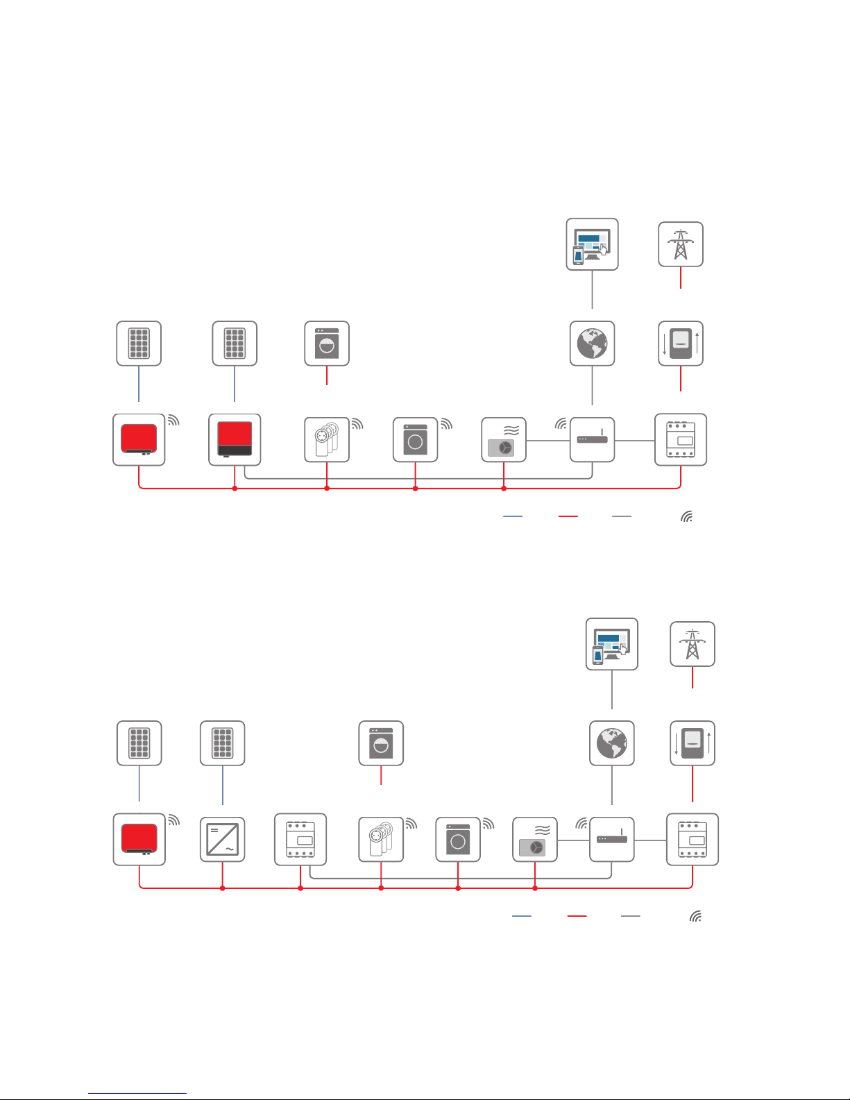
4.4 System Structure
The SunnyHomeManager has an integrated measuring device. Depending on the application, the
SunnyHomeManager is integrated and configured differently in the system (see Section8.2, page33):
PV system with SMA inverters and measurement at the grid-connection point (recommended)
SUNNY PORTAL
INTERNET
SUNNY HOME
MANAGER 2.0
Ethernet
SUNNY BOY 1.5/2.5 SUNNY BOY TL
UTILITY GRID
PV MODULES
ROUTER
UTILITY METER
FOR BILLING
PURPOSES
INTELLIGENT
APPLIANCE
via ETHERNET
RADIO-CONTROLLED
SOCKETS
via WLAN
INTELLIGENT
APPLIANCE
via WLAN
APPLIANCE
WLAN
AC
DC
PV MODULES
PV system with inverters of other manufacturers and measurement at the grid-connection point
and the PV generation using a SunnyHomeManager and an SMAEnergyMeter
SUNNY PORTAL
INTERNET
SMA ENERGY METER
Ethernet
SUNNY BOY 1.5/2.5
SUNNY HOME
MANAGER 2.0
UTILITY GRID
PV MODULES
ROUTER
UTILITY METER
FOR BILLING
PURPOSES
INTELLIGENT
APPLIANCE
via ETHERNET
RADIO-CONTROLLED
SOCKETS
via WLAN
INTELLIGENT
APPLIANCE
via WLAN
APPLIANCE
WLAN
AC
DC
PV MODULES
PV INVERTER
4Product Description
SMA Solar Technology AG
Operating ManualHM-20-BE-en-1024
Page 25

SunnyHomeManager without using the integrated measuring device
SUNNY PORTAL
INTERNET
SMA ENERGY METER
Ethernet
SUNNY BOY 1.5/2.5
SUNNY HOME
MANAGER 2.0
L1 / N
UTILITY GRID
PV MODULES
ROUTER
UTILITY METER
FOR BILLING
PURPOSES
INTELLIGENT
APPLIANCE
via ETHERNET
RADIO-CONTROLLED
SOCKETS
via WLAN
INTELLIGENT
APPLIANCE
via WLAN
APPLIANCE
WLAN
AC
DC
4 Product Description
SMA Solar Technology AG
Operating Manual 25HM-20-BE-en-10
Page 26

5 Mounting
5.1 Requirements for Mounting the SunnyHomeManager
☐ The mounting location must be indoors.
☐ The SunnyHomeManager must be installed in a switch cabinet.
☐ The mounting location must be protected against dust, moisture and corrosive substances.
☐ The cable route from the mounting location to the router must not exceed a maximum length of 100m.
☐ A minimum distance of 1m must be maintained from devices using the 2.4GHz radio spectrum (e.g. WLAN
devices, microwave ovens). This will prevent reduced connection quality and data transmission speed.
☐ The ambient conditions at the mounting location must be suitable for the operation of the SunnyHomeManager
(see Section21, page124).
5.2 Mounting the SunnyHomeManager on the Top-Hat Rail
Requirement:
☐ The top-hat rail must be securely mounted in the switch cabinet.
Procedure:
1. Press the SunnyHomeManager with the upper retainers into
the upper edge of the top-hat rail.
2. Hook the lower retainers into the lower edge of the top-hat rail.
5Mounting
SMA Solar Technology AG
Operating ManualHM-20-BE-en-1026
Page 27

6 Preparing for Speedwire Communication
If the SunnyHomeManager is to communicate with other SMA devices via Speedwire, the SunnyHomeManager
and the Speedwire devices must be in the same local network. Perform the following preparatory steps.
Inverters with Webconnect function
If an inverter is already registered in SunnyPortal with the Webconnect function, the inverter cannot be added to
the SunnyHomeManager system in SunnyPortal.
• In order to be able to add the inverter to the SunnyHomeManager system in SunnyPortal, delete the
inverter with Webconnect function from the Webconnect system in SunnyPortal or deactivate data reception
for the inverter in the Webconnect system in SunnyPortal.
Requirements:
☐ DHCP must be active on the router (see router documentation). If your router does not support DHCP, you can
configure the static network settings on the Speedwire device using SMAConnectionAssist.
☐ All UDP ports > 1024 on the router or modem must be open for outgoing connections. If there is a firewall
installed on the router or modem, you might have to adjust the firewall rules.
☐ It must be possible for the outgoing router or modem connections to reach all Internet destinations (target IP,
target port). If there is a firewall installed on the router or modem, you might have to adjust the firewall rules.
☐ On the router or modem with NAT (Network Address Translation), no port forwarding must be entered. Potential
communication problems can thus be prevented.
☐ There must be no packet filtering or manipulation for SIP packets on the router or modem.
☐ The routers and network switches with router function must forward the Multicast telegrams (telegrams with
destination address 239.0.0.0 to 239.255.255.255) required for the Speedwire connection to all nodes of the
Speedwire network.
☐ All network components used must support the IGMP protocol, minimum version3 (IGMPv3) (see network
component documentation).
Procedure:
1.
Deactivating the BLUETOOTH communication of the inverters
If an inverter communicates simultaneously via Speedwire/WLAN and BLUETOOTH, data recording errors
will result. The SunnyHomeManager does not support communication with BLUETOOTH.
• For inverters with BLUETOOTHinterface, set NetID0 (see inverter- or BLUETOOTHPiggy-Back
documentation). This deactivates communication via BLUETOOTH.
2. Connect the Speedwire devices to the router / network switch (see Speedwire device documentation). Make sure
that the distance to the mounting location of the SunnyHomeManager is not too great, as the
SunnyHomeManager must later be connected to the same router/network switch.
6 Preparing for Speedwire Communication
SMA Solar Technology AG
Operating Manual 27HM-20-BE-en-10
Page 28

7 Connection
7.1 Connecting the SunnyHomeManager to the Router
1. Connect the network cable to the network terminal of the
SunnyHomeManager. The network cable must be suitable for
connection to the SunnyHomeManager (see Section4.1.4
"System Requirements", page21).
R
eset
SUNNY HOME MANA
GER 2.0
2. Connect the other end of the network cable to the router.
7.2 Connecting the SunnyHomeManager to the SMAEnergyMeter
The SMAEnergyMeter and the SunnyHomeManager must be connected to the same router.
Additionally required material (not included in the scope of delivery):
☐ 1 network cable (see Section4.1.4 "System Requirements", page21)
Procedure:
1. Connect the SMAEnergyMeter to the router (see SMAEnergyMeter installation manual).
2. Connect the SunnyHomeManager to the router (see Section7.1, page28).
7.3 Replacing the SMAEnergyMeter
1. Write down the serial number of the new SMAEnergyMeter. The serial number is to be found on the type label
of the SMAEnergyMeter.
2. Configure the new SMAEnergyMeter in SunnyPortal (see Section12.6 "Configuring the Energy Meter",
page67).
7.4 Connecting a Smart Appliance
Some modern home appliances have an Ethernet connection with which the data of the device can be called up via
the local network. If there is an Internet connection via the network router, the manufacturers of household devices can
use this data for maintenance purposes, for example. Visualization and control of the household devices via mobile
devices (e.g. via app in the Smartphone) is also possible with this. If the manufacturer of the networked household
devices, in cooperation with SMA Solar Technology AG, has implemented a special data exchange protocol for
energy management in the device control, the SunnyHomeManager can control these loads directly via the local
network. For information on the supported products (see Section2.3, page11). The smart appliances send information
on the load type, the planned energy requirement, and the preferred operating time period to the
SunnyHomeManager. The SunnyHomeManager factors this information into its load control, and also taking the
configured optimization targets in the context of load control into account, sends appropriate start and stop signals to
the loads.
Requirements:
☐ The device must support the data exchange protocol defined by SMA Solar Technology AG.
☐ The SunnyHomeManager must be located in the same local network as the device.
7Connection
SMA Solar Technology AG
Operating ManualHM-20-BE-en-1028
Page 29

Additionally required material (not included in the scope of delivery):
☐ 1 network cable (see Section4.1.4, page21)
Procedure:
1. Connect the network cable to the device (see device documentation).
2. Connect the other end of the network cable to the router or network switch.
☑ The device is automatically recognized by the SunnyHomeManager. Once you have added the controllable
device to the SunnyHomeManager system via the configuration wizard in SunnyPortal, the
SunnyHomeManager will control the device automatically via the defined data exchange protocol.
Pairing
In the case of EEBus compatible home appliances, a pairing must be performed. The new device will appear in
SunnyPortal only once the pairing has been completed successfully (see technical information: "SMA SMART
HOME - Home appliance energy management using EEBus").
7.5 Voltage supply terminal
7.5.1 Requirements for connecting the voltage supply
Danger to life due to electric shock if external disconnect switch is missing
Lethal voltages are present in the live components.
• Install an external disconnect switch between the product and the grid-connection point. The external
disconnector must be close to the product and easily accessible.
Danger to life due to electric shock
Lethal voltages are present in the live components.
• Disconnect the connection point from voltage sources and make sure it cannot be reconnected.
• Before performing any work on the product, disconnect the grid side from all voltage sources using the installed
disconnect switch.
• Ensure that the conductors to be connected are de-energized.
• Only use the product in a dry environment and keep it away from moisture.
• Install the product in the switch cabinet only and ensure that the connection areas for the line conductors and
the neutral conductor are behind a cover or have contact protection.
• Disconnect the product from voltage sources before cleaning and clean it with a dry cloth only.
• Observe the prescribed minimum clearance between the network cable and live installation components, or use
suitable insulation.
Requirements:
☐ The setpoints of the electric utility company must be observed.
☐ At least the line conductor L1 and the neutral conductor must be connected. As a result, the
SunnyHomeManager is supplied with voltage.
☐ When using fine stranded conductors, bootlace ferrules must be used.
Cable requirements:
☐ Conductor cross-section without current transformer:10 to 16 mm²
7 Connection
SMA Solar Technology AG
Operating Manual 29HM-20-BE-en-10
Page 30

☐ Conductor cross-section with current transformer: see recommendations of the current transformer manufacturer
7.5.2 Connecting the Voltage Supply for Applications up to 63 A
L1L2L3
N
SUNNY HOME MANAGER 2.0
L1 L2 L3
Reset
L1 L2 L3
NL1 L2 L3
L1 L2 L3
L1 L2 L3
N
Router/
Switch
Sunny
Portal
Internet
WLAN
Ethernet
OUT
IN
Household
Disconnect switch
Energy meter of
the electric
utility company
Main breaker
(three-phase)
Utility grid
Inverters
Sunny Home Manager 2.0
as purchased electricity
and feed-in meter
L1, L2, L3: Line conductor
N: Neutral conductor
OUT: Meter output, load side
IN: Meter input, grid side
Figure 4: The following figure shows a connection example in TN and TT utility grids in the case of installation at the grid-connection point when
using the integrated measuring unit.
Procedure:
1. Disconnect the connection point from voltage sources and make sure it cannot be reconnected.
2. Connect the line conductors to the SunnyHomeManager:
• When using the integrated measuring device and a three-phase utility grid, connect the line conductors L1,
L2, L3 and N to the screw terminals at the input of the SunnyHomeManager. Open each screw terminal
using a cross-head screwdriver, insert the conductor into the contact terminal and tighten the screw using a
cross-head screwdriver (torque: 2.0Nm).
• When using the integrated measuring device and the single-phase utility grid, connect the line conductors L1
and N to the screw terminals at the input of the SunnyHomeManager. Open each screw terminal using a
cross-head screwdriver, insert the conductor into the contact terminal and tighten the screw using a crosshead screwdriver (torque: 2.0Nm).
• When not using the integrated measuring device, connect the line conductor L1 and the neutral conductor to
the screw terminals at the input of the SunnyHomeManager. Open each screw terminal using a cross-head
screwdriver, insert the conductor into the contact terminal and tighten the screw using a cross-head
screwdriver (torque: 2.0Nm).
7Connection
SMA Solar Technology AG
Operating ManualHM-20-BE-en-1030
Page 31

• When using the integrated measuring device for measuring the PV generation output, connect the
SunnyHomeManager to the common connection point of all PV inverters in the household grid. An
SMAEnergyMeter must be installed at the grid-connection point for this.
3. Retighten the screw terminals after six to eight weeks (torque: 2.0Nm).
7.5.3 Connecting the Voltage Supply for Applications greater than 63 A
L1
L2
L3
N
L1
L2
L3
N
k/S1
l/S2
N
L1
L2
L3
k/S1
l/S2
k/S1
l/S2
L1
L2
L3
OUT
IN
L1
L2
L3
L1L2L3
N
SUNNY HOME MANAGER 2.0
L1 L2 L3
Reset
Connection cable for voltage measurement
Current
transformer 2
Current
transformer 1
Loads
Disconnect switch
Energy meter
of the
electric utility company
Main breaker
(three-phase)
Utility grid
Connection cable for current measurement
Current
transformer 3
L1, L2, L3: Line conductor
N: Neutral conductor
OUT: Meter output, load side
IN: Meter input, grid side
Figure 5: The following figure shows a connection example in TN and TT utility grids in the case of installation at the grid-connection point.
Additionally required material (not included in the scope of delivery):
☐ 3 x current transformers (SMA Solar Technology AG recommends current transformer for 5 A secondary current.
The current transformers should have at least accuracy class 1.)
☐ Connection cables for current transformers
Procedure:
1. Disconnect the connection point from voltage sources and make sure it cannot be reconnected.
2. Connect one current transformer to each line conductor L1, L2 and L3.
3. On each current transformer, connect one connection cable for current measurement to each of the secondary
current terminals (k/S1 and l/S2).
4. Connect the connection cables for current measurement (dashed gray line) to the screw terminals L1, L2 and L3
of the SunnyHomeManager. To do this, open each screw terminal using a cross-head screwdriver, insert the
conductor into the contact terminal and tighten the screw using a cross-head screwdriver (torque: 2.0Nm).
7 Connection
SMA Solar Technology AG
Operating Manual 31HM-20-BE-en-10
Page 32

5. Connect the connection cables for voltage measurement (solid gray line) to the screw terminals L1, L2 and L3 at
the output of the SunnyHomeManager. To do this, open each screw terminal using a cross-head screwdriver,
insert the conductor into the contact terminal and tighten the screw using a cross-head screwdriver (torque:
2.0Nm).
6. Connect the connection cables for voltage measurement L1, L2 and L3 (solid gray line) to the corresponding line
conductors L1, L2 and L3.
7Connection
SMA Solar Technology AG
Operating ManualHM-20-BE-en-1032
Page 33

8 Commissioning
8.1 Testing the Connection to SunnyPortal
The SunnyHomeManager automatically establishes a connection to SunnyPortal. You can test whether there is a
connection to SunnyPortal if you proceed as described in the following.
Requirements:
☐ DHCP must be active for the router (see router manual). If your router does not support DHCP, you can configure
the static network settings on the SunnyHomeManager using the SunnyHomeManagerAssistant (see
Section19.3 "Using the SunnyHomeManagerAssistant", page115).
☐ The SunnyHomeManager must be connected to the router (see Section7.1 "Connecting the
SunnyHomeManager to the Router", page28).
☐ The SunnyHomeManager must be supplied with voltage (see the installation manual of the
SunnyHomeManager).
Procedure:
1. Check whether the status LED of the SunnyHomeManager is glowing green and whether the performance LED is
off.
☑ The status LED of the SunnyHomeManager is glowing green and the performance LED is off. There is a
connection to SunnyPortal. You can register the SunnyHomeManager in SunnyPortal (see Section8.2
"Registering in SunnyPortal", page33).
✖ The status LED or the performance LED is continuously flashing red?
The SunnyHomeManager cannot establish the connection to SunnyPortal automatically. This is the case,
forexample, if there is a proxy server in your network or if your router does not support DHCP.
• Use the SunnyHomeManagerAssistant (see Section19.3 "Using the SunnyHomeManagerAssistant",
page115).
2. Check whether the status LED of the SunnyHomeManager is glowing green and whether the performance LED is
glowing green.
☑ The connection to and registration in SunnyPortal have already been executed. Use your user data to log on
to SunnyPortal (see Section8.3 "Logging In and Out of SunnyPortal", page38).
8.2 Registering in SunnyPortal
SunnyPortal serves as the user interface of the SunnyHomeManager. Therefore, you must register the
SunnyHomeManager in SunnyPortal.
Requirements:
☐ The PV system and all devices in the local network must be in operation and connected to the
SunnyHomeManager via a router/network switch.
☐ The registration ID (RID) and the identification key (PIC) from the SunnyHomeManager type label must be
available.
☐ NetID 0 must be set for Speedwire devices with integrated BLUETOOTH interface.
☐ The status LED must glow green and the performance LED must be off.
8 Commissioning
SMA Solar Technology AG
Operating Manual 33HM-20-BE-en-10
Page 34

Procedure:
1. Start the PV System Setup Assistant.
2. Register as a new user in SunnyPortal.
or
Log in to SunnyPortal as an existing user.
3. Create a SunnyHomeManager system in SunnyPortal.
Starting the PV System Setup Assistant
The PV System Setup Assistant is a step-by-step guide of the processes required for user registration and the registration
of SunnyHomeManager systems in SunnyPortal.
Procedure:
1. Open www.SunnyPortal.com and select [PV System Setup Assistant].
or
Go to www.SunnyPortal.com/Register.
☑ The PVSystem Setup Assistant opens.
2. Select [Next].
☑ The page User registration opens.
Register as a new user in SunnyPortal.
1. Activate the field I am not yet registered and select [Next].
2. Enter the necessary data for registration.
3. Select [Next].
☑ After a few minutes you will receive an e-mail containing a link and your access data to SunnyPortal.
✖ You did not receive an e-mail from SunnyPortal?
The e-mail may have been automatically redirected to your spam mail folder.
• Check whether the e-mail is in the spam mail folder.
✖ You did not receive an e-mail from SunnyPortal?
You may have stated a different e-mail address.
• Check whether the e-mail was sent to another e-mail address.
• If the other e-mail address is an unknown address, restart the PV System Setup Assistant and register as a
new user again.
4. Follow the link in the confirmation e-mail within 24 hours.
☑ SunnyPortal opens a separate window to confirm successful registration.
5. Select [Next].
6. The page Select PV system opens.
Log in to SunnyPortal as an existing user.
Requirement:
☐ You must already have a PV system in SunnyPortal.
8Commissioning
SMA Solar Technology AG
Operating ManualHM-20-BE-en-1034
Page 35

Procedure:
1. Select the field I am already registered in SunnyPortal.
2. Enter the e-mail address and the SunnyPortal password in the fields SunnyPortal e-mail address and
Password.
3. Select [Next].
☑ The page Select PV system opens.
Creating a SunnyHomeManager System in SunnyPortal
All devices with an identical password form a system. For this reason, a password used for all devices in a system is
called a system password. The system password is the same as the device password for the user group Installer.
Requirements:
☐ Either a uniform user-defined system password or the factory-set standard password 1111 must be set on all
Speedwire devices for the user group Installer. If necessary, set a uniform system password for all Speedwire
devices (see SunnyExplorer Help).
Procedure:
1. Activate the field Create a new PV system and enter a system name (e.g. My SunnyHomeManager
system).
2. In the window for entering the system password, enter the system password of the user role Installer:
• If the standard password 1111 is still set on all devices for the user group Installer, enter a new system
password.
• If a different uniform password has already been set on all devices, enter this password as the system
password.
• If a uniform password has not been set on all devices, set a uniform password for the user group Installer
using the SunnyExplorer software (see SunnyExplorer help) and enter this password in the PV System Setup
Assistant as the system password.
3. Enter the system password again in the field Repeat password.
4. Select [Next].
☑ The page Select devices opens.
5. Enter the serial number of the SunnyHomeManager in the field PIC. Enter the registration ID of the
SunnyHomeManager in the field RID.
6. Select [Identify].
☑ SunnyPortal searches for the SunnyHomeManager with the corresponding serial number and registration
ID. The PV System Setup Assistant displays the correct SunnyHomeManager with a green tick.
✖ The PV System Setup Assistant cannot find any SunnyHomeManager with the entered serial number and
registration ID?
• See Troubleshooting (see Section19 "Troubleshooting", page112).
8 Commissioning
SMA Solar Technology AG
Operating Manual 35HM-20-BE-en-10
Page 36

7. Select [Next].
☑ The SunnyHomeManager now searches for devices in the local network. After a maximum of ten minutes
the PV System Setup Assistant lists the serial numbers of any available devices in the local network.
✖ The PV System Setup Assistant cannot establish a connection to the SunnyHomeManager and to the
Speedwire devices?
or
The PV System Setup Assistant lists none or not all of the Speedwire devices in your PV system?
• Select [Refresh]. If the PV System Setup Assistant continues to list none or not all of the Speedwire
devices, see Troubleshooting (see Section19.2 "Errors during Registration in SunnyPortal", page112).
✖ The PV System Setup Assistant lists own and third-party devices?
• See Troubleshooting (see Section19 "Troubleshooting", page112).
8. Activate the checkboxes of the devices you wish to add to the SunnyHomeManager system. Tip: You can
identify devices using the previously noted serial numbers.
9. Select [Add] to add the devices to the SunnyHomeManager system immediately.
☑ The system password is transferred to the devices. This process can take several minutes. The devices are
then shown with a green tick.
✖ Some devices are shown with the warning symbol?
SunnyHomeManager cannot access the devices. You may have entered an invalid system password or the
connection to the devices could not be established.
• See Troubleshooting (see Section19 "Troubleshooting", page112).
10. Select [Skip forward] to add the devices to the SunnyHomeManager system at a later time and continue with
registration. Tip: You can add the devices to the SunnyHomeManager system as new devices after registration
(see Section14 "System Management", page84).
☑ The window Meter Configuration opens.
11. Select [Next].
☑ The window Meter Configuration opens.
Configuring the EnergyMeter
1. In the Meter Configuration area, select the desired feed-in and purchased electricity meter or PV production
meter from the drop-down list:
Application Configuration
PV system with SMA inverters and measurement at the
grid-connection point
• Select the entry Internal EnergyMeter in the
Purchased Electricity and Grid feed-in
dropdown-list.
• Select the entry No energy meter in the PV
Generation drop-down list.
8Commissioning
SMA Solar Technology AG
Operating ManualHM-20-BE-en-1036
Page 37

Application Configuration
PV systems with inverters of other manufacturers and
measurement at the grid-connection point and PV generation using a SunnyHomeManager and an
SMAEnergyMeter.
When connecting the SunnyHomeManager to the
grid-connection point and the SMAEnergyMeter to
measure the PV generation.
• Select the entry Internal EnergyMeter in the
Purchased Electricity and Grid feed-in
dropdown-list.
• Select the entry SMAEnergyMeter xxx in the
PV Generation drop-down list. Here, xxx is the
placeholder for the SMAEnergyMeter serial
number. If there are two SMAEnergyMeters in
the PV system, select the desired
SMAEnergyMeter.
PV systems with inverters of other manufacturers and
measurement at the grid-connection point and PV generation using a SunnyHomeManager and an
SMAEnergyMeter.
When connecting the SunnyHomeManager to the
grid-connection point and the SunnyHomeManager
to measure the PV generation:
• Select the entry SMAEnergyMeter xxx in the
Purchased Electricity and Grid feed-in dropdown list. Here, xxx is the placeholder for the
SMAEnergyMeter serial number. If there are two
SMAEnergyMeters in the PV system, select the
desired SMAEnergyMeter.
• Select the entry Internal EnergyMeter in the
PV Generation drop-down list.
PV system with existing SMAEnergyMeters
• Select the entry SMAEnergyMeter xxx in the
Purchased Electricity and Grid feed-in dropdown list. Here, xxx is the placeholder for the
SMAEnergyMeter serial number. If there are two
SMAEnergyMeters in the PV system, select the
desired SMAEnergyMeter.
• Select the entry SMAEnergyMeter xxx in the
PV Generation drop-down list. Here, xxx is the
placeholder for the SMAEnergyMeter serial
number. If there are two SMAEnergyMeters in
the PV system, select the desired
SMAEnergyMeter.
2. Select [Next].
☑ The page Extended PV System Properties opens.
Entering the PV System Data
1. Enter the PV system data.
2. Select [Next].
☑ The PV System Setup Assistant shows a summary of your entered data.
3. Select [Finish].
☑ SunnyPortal confirms successful registration of the SunnyHomeManager system in a separate window.
8 Commissioning
SMA Solar Technology AG
Operating Manual 37HM-20-BE-en-10
Page 38

4. To go to the SunnyHomeManager system, select [To the PV system].
☑ The SunnyHomeManager system opens.
5. Enter further PV system properties (see Section16 "System Settings", page96):
• Add automatically recognized devices
• Configure the load profiles of the automatically recognized devices
• Enter the string configuration
• Enter the operator data
• Enter the PV array power
• Enter the feed-in tariff, self-consumption tariff and electricity tariff
• Configure settings for PV system monitoring
8.3 Logging In and Out of SunnyPortal
Logging into SunnyPortal
Requirement:
☐ The SunnyHomeManager must be registered with the PVSystemSetupAssistant in SunnyPortal (see Section8.2
"Registering in SunnyPortal", page33).
Procedure:
1. Go to www.SunnyPortal.com.
2. In the Login area, enter the e-mail address in the field E-mail.
3. Enter the SunnyPortal password in the field Password.
4. Activate the SSL checkbox to transmit the encrypted login data.
5. Activate the checkbox Remain logged in to stay logged in for your next SunnyPortal visits. This way, you stay
logged into SunnyPortal until you log out via the user interface.
6. Select [Login].
Logging out of SunnyPortal
When you log out of SunnyPortal user interface, your PV system will be protected against unauthorized access.
Procedure:
• Select your user name in the header of the user interface and select [Logout].
8Commissioning
SMA Solar Technology AG
Operating ManualHM-20-BE-en-1038
Page 39

9 Accessing the User Interface of the SunnyHomeManager System
If you have only created one system in SunnyPortal, you will automatically access the user interface of this
SunnyHomeManager system after logging into SunnyPortal. If you have several systems in SunnyPortal, you will
need to access the user interface of the SunnyHomeManager system after logging into SunnyPortal.
Procedure:
1. Log into SunnyPortal (see Section8.3, page38).
2. Select PV System Selection > "My SunnyHomeManager system" in the page and menu selection.
☑ The user interface of the SunnyHomeManager system opens.
A
B
C
D
D
Figure 6: User interface of the SunnyHomeManager system in SunnyPortal (example)
Position Designation Explanation
A Header • Selection of the user interface language
• Logout from SunnyPortal
B Contents area • Contents of the selected page
C Page and menu selection • Access to the various pages and menus of the
SunnyHomeManager system
D Help • Explanation of the content of the selected page
• Link to SunnyPortal help
9 Accessing the User Interface of the Sunny Home Manager System
SMA Solar Technology AG
Operating Manual 39HM-20-BE-en-10
Page 40

10 Page and Menu Selection
10.1 System Selection and System List
The following is required to display the menu item and page:
☐ Your e-mail address must be assigned to more than one system in SunnyPortal.
System Selection Menu Item
Under the menu item Select PV system, you can select the desired system (see Section9, page39).
System List Page
The following data is shown for each system:
• Nominal PV system power in kWp
• Total yield so far
• Total yield for the following time periods:
– Current day
– Previous day
– Current month
• Specific system yield (kWh/kWp) for the following time periods:
– Current month
– Current year
By default, the system list is sorted in ascending order in accordance with the specific system yield. You can also sort
the system list by other values and in descending order (see Section11, page63).
10.2 My SunnyHomeManager System
10.2.1 PV System Profile
SunnyPortal compiles the PV system profile from information that you can enter in different SunnyPortal pages.
The following information can be displayed in the PV system profile:
Information Configuration, see Section
Location Section16.2, page97
Operator Section16.6, page99
Commissioning Section16.2, page97
Nominal system power Section16.4, page98
Annual production Section16.13, page104
CO2 avoided Section16.12, page104
Modules Section16.4, page98
Tilt angle Section12.10, page70
Tracking
10Page and Menu Selection
SMA Solar Technology AG
Operating ManualHM-20-BE-en-1040
Page 41

Information Configuration, see Section
Inverter SunnyPortal receives this information from the devices.
Communication
Description Section16.5, page99
PV system image Section16.7, page99
10.2.2 Current Status And Forecast
The SunnyHomeManager continuously logs the energy generated by the PV system. The SunnyHomeManager also
receives location-based weather forecasts via the Internet. Based on this information, the SunnyHomeManager
creates a PV yield forecast for the PV system.
The data for the generated energy can only be fully displayed if the integrated measuring device or an externally
assigned SMAEnergyMeter measures the energy flow at the grid-connection point.
The SunnyHomeManager receives the PV generation data via the connected SMA inverters or via an optionally
connected SMAEnergyMeter, which measures the PV generation output of the local PV system.
To query forecast information, you must fill in the following input fields on the System properties page in
SunnyPortal:
• Latitude
• Longitude
• Nominal PV system power (necessary for the correct power forecast)
If one of the three entries is missing, either the weather symbols are not displayed, the power forecast is not present, or
it is incorrect.
Current Status Area
The following is required to display the current status area:
☐ The data request interval must be set to Automatic (see Section12.7, page68).
Changing the display
In the area Current status you can choose between the displays OptionI and OptionII.
• Select the page Current status and Forecast in the page and menu selection.
• Select [Configuration - Current Status and Forecast] in the contents area below.
• Select the desired option in the field Display.
Figure 7: Display: left Option I and right Option II (examples)
10 Page and Menu Selection
SMA Solar Technology AG
Operating Manual 41HM-20-BE-en-10
Page 42

Option I:
The display Option I contains the following current data:
Designation Explanation
PV generation Currently generated power of your PV system
Grid feed-in Power that your system is currently feeding into the utility grid
If your system is generating more power than your household needs at the moment or can be stored in the battery, the surplus power is fed into the utility grid.
Self-consumption Power that your household is currently drawing from your system and, if applica-
ble, being stored into the battery from your system.
Purchased electricity Power that your household is currently drawing from the utility grid
Total consumption Power that your household is currently drawing from the utility grid
Self-consumption quota Current ratio of self-consumption to PV power
Battery discharging* Power that your household is currently drawing from the battery
Battery state of charge* Current state of charge of the battery in percent, in relation to the battery capac-
ity
* Only displayed for PV systems with battery
Option II:
The display Option I contains the following current data:
Designation Explanation
PV generation Currently generated power of your PV system
Consumption
(Total consumption)
Power that your household is currently drawing from your system, the utility grid
and, if applicable, your battery
The colors visualize which portion of the consumption is currently made up of purchased electricity, direct consumption (PV system) and, if applicable, battery discharging.
Purchased electricity Power that your household is currently drawing from the utility grid
Grid feed-in Power that your system is currently feeding into the utility grid
If your system is generating more power than your household needs at the moment or can be stored in the battery, the surplus power is fed into the utility grid.
Battery charging* Power that is being currently charged from your system into the battery
Battery discharging* Power that your household is currently drawing from the battery
10Page and Menu Selection
SMA Solar Technology AG
Operating ManualHM-20-BE-en-1042
Page 43

Designation Explanation
Self-sufficiency quota Current ratio of internal power supply to total consumption
Internal power supply: Power that your household is drawing directly from your
system (direct consumption) and, if applicable, from the battery (battery discharging).
In systems without batteries, the self-consumption is the same as the internal
power supply.
Self-consumption quota Current ratio of self-consumption to PV power
Self-consumption: the power that your household draws directly from your system
(direct consumption) and, if applicable, the power that your system stores in the
battery (battery charging).
* Only displayed for PV systems with battery
Forecast and Recommended Action Area
The Forecast and Recommended Action diagram visualizes the following information:
• Tariff for the electric current purchased from the utility grid
• Expected PV power
• Weather forecast for the current date (The data is not available in all countries.)
• Scheduled time periods for operation of the loads
You can have a forecast displayed for up to 48 hours from the currently selected time.
10 Page and Menu Selection
SMA Solar Technology AG
Operating Manual 43HM-20-BE-en-10
Page 44

Tip: Click on the diagram, hold down the left mouse button and move the mouse to the right or left. This way you can
select a different time period.
A
B
D
C
E
F
Figure 8: Forecast and Recommended Action diagram (example)
Position Explanation
A Weather forecast
B Suitable time for manually switching on loads
The SunnyHomeManager takes the following information into consideration for the recommended action:
• Expected PV power (see position D)
• Expected energy consumption of the household and of loads for which the
SunnyHomeManager receives measured values of the power consumed via radiocontrolled sockets or via direct communication.
• The SunnyHomeManager determines the anticipated energy consumption in
accordance with the consumption forecast based on the "learned" consumption
behavior of the individual household.
• Feed-in tariff (see Section16.8, page101)
• Electricity tariff (see Section16.8, page101)
• Optimization target (see Section16.11, page103)
• Azimuth and tilt angle (see Section16.1, page96)
10Page and Menu Selection
SMA Solar Technology AG
Operating ManualHM-20-BE-en-1044
Page 45

Position Explanation
C Expected PV power in accordance with the PV yield forecast
The SunnyHomeManager determines the PV power that can be expected in each case using the weather forecast for the selected location and the "learned" behavior of the system.
Tip: When you move the mouse over one of the bars, the following details for this time period
will be displayed in a window:
• Estimated PV generation
• Estimated consumption
• Difference between the estimated PV generation and estimated consumption
D Tariff for the electric current purchased from the utility grid
• Red: expensive
• Green: good value
If you have only entered one electricity tariff, green is always displayed.
• Other colors: electricity tariffs between the highest and the lowest electricity tariff
E View of the time periods for the planned operation of the loads (load prognosis)
• The configured time periods are shown as colored, semi-transparent bars.
• Time periods in which the loads were actually in operation or are going to be in
operation are shown as colored, solid bars.
F Loads legend
The legend shows which color is assigned to which load in the time-period view (E).
10.2.3 Energy Balance
Requirements for displaying the page:
☐ The integrated measuring device or an externally assigned SMAEnergyMeter must measure the energy flow at
the grid-connection point.
The additionally required PV generation data will be determined either directly by the connected SMA inverters or can
be captured via an additional PV production meter in PV systems with SunnyHomeManager.
Display with Battery
If a battery inverter is present in your system, you can select between the simplified view without battery data and the
detailed view with battery data.
• To display the data of the battery in the diagram and in the area Energy balance, activate the checkbox
Detailed view.
• To avoid displaying the data of the battery in the diagram and in the area Energy Balance, deactivate the
checkbox Detailed view.
Showing and Hiding Diagram Data
You can show and hide the diagram data indicated in the legend by clicking on the respective entry in the legend.
10 Page and Menu Selection
SMA Solar Technology AG
Operating Manual 45HM-20-BE-en-10
Page 46

The page Energy balance includes the following tabs:
Tab Content
Current
Data in the Consumption diagram:
• Current value of consumption: Power that your household is currently
drawing from your system (direct consumption or internal power supply for
systems without battery), from the utility grid (purchased electricity) and, if
applicable, from the battery (battery discharging)
• Purchased electricity: Power that is currently being drawn by your
household from the utility grid
• Internal power supply: Power that is currently being supplied to your
household by your system
For systems with battery, the power comes preferably directly from the
system (direct consumption). If the power produced by the system is not
sufficient, the remaining power is supplied by discharging the battery.
• Battery discharging (only displayed for systems with battery): Power that
your household is currently drawing from the battery
• Direct consumption (only displayed for systems with battery): Power that
your household is currently drawing from your system, without intermediate
storage in the battery
Current
Data in the Generation diagram:
• Current Power: Power that your system is currently generating
• Self-consumption: Power that your household is currently drawing directly
from your system (direct consumption) and the power that your PV system is
currently storing in the battery (battery charging)
In systems without batteries, self-consumption is the same as internal power
supply.
• Battery charging (only displayed for systems with battery): Power that
your system is currently storing in the battery
• Grid feed-in: Power that your system is currently feeding in to the utility grid
If your system is producing more power than your household needs at the
moment or can be stored in the battery, the surplus power is fed into the
utility grid.
10Page and Menu Selection
SMA Solar Technology AG
Operating ManualHM-20-BE-en-1046
Page 47

Tab Content
Current Additional data:
• Self-consumption rate: Current ratio of self-consumption to PV power
• Direct consumption quota (only displayed for systems with battery):
Current ratio of direct consumption to PV power
• Self-sufficiency quota: Current ratio of internal power supply to total
consumption
• Limiting of the active power feed-in: Will only be displayed for
SunnyHomeManager systems if you have set active power feed-in
limitation for your PV system. A red line will indicate the maximum amount of
active power that may be fed into If you have limited the active power feedin to 0%, the red line runs directly on the x-axis of the diagram. Limitation of
the active power feed-in to 0% is only supported by inverters that support
the fallback function (fallback: in the event of a communication failure
between the SunnyHomeManager and the inverter, the inverter reverts to
an output power of 0watts). For more information see the inverter manual at
www.SMA-Solar.com.
Day
Data in the Consumption diagram:
• Daily consumption: Energy that your household drew from your PV system
(direct consumption or internal power supply for systems without battery),
the utility grid (purchased electricity) and, if applicable, the battery (battery
discharging) on the day selected
• Purchased electricity: Energy that your household drew from the utility
grid on the day selected
• Internal power supply: Energy that was supplied to your household by
your PV system on the day selected
For systems with battery, the energy comes preferably directly from the
system (direct consumption). If the power produced by the system is not
sufficient, the remaining power is supplied by discharging the battery.
• Battery discharging (only displayed for systems with battery): Energy that
your household drew from the battery on the day selected
• Direct consumption (only displayed for systems with battery): Energy that
your household drew directly from your PV system on the day selected,
without intermediate storage in the battery
Day
Data in the Generation diagram:
• Daily yield: Energy that your system generated on the day selected
• Self-consumption: Energy that your household drew directly from your
system on the day selected (direct consumption) and the energy that your
system stored in the battery (battery charging) on the day selected
• Battery charging (only displayed for systems with battery): Energy that
your system stored in the battery on the day selected
• Grid feed-in: Energy fed by your system into the utility grid on the day
selected
10 Page and Menu Selection
SMA Solar Technology AG
Operating Manual 47HM-20-BE-en-10
Page 48

Tab Content
Day Additional data:
• Self-consumption rate: Ratio of self-consumption to daily yield
• Direct consumption quota (only displayed for systems with battery): Ratio
of direct consumption to daily yield
• Self-sufficiency quota: Ratio of internal power supply to daily consumption
• Limiting of the active power feed-in: If you have set a limit to active
power feed-in for your system, a red line will indicate the maximum amount
of active power permitted to be fed into the utility grid. If you have limited
the active power feed-in to 0%, the red line runs directly on the x-axis of the
diagram.
Month
Data in the Consumption diagram:
• Monthly consumption: Energy that your household drew from your system
(direct consumption or internal power supply for systems without battery),
the utility grid (purchased electricity) and, if applicable, the battery (battery
discharging) during the month selected.
• Purchased electricity: Energy that your household drew from the utility
grid during the month selected
• Internal power supply: Energy that was supplied to your household by
your PV system during the month selected
For systems with battery, the energy comes preferably directly from the
system (direct consumption). If the power produced by the system is not
sufficient, the remaining power is supplied by discharging the battery.
• Battery discharging (only displayed for systems with battery): Energy that
your household drew from the battery during the month selected
• Direct consumption (only displayed for systems with battery): Energy that
your household drew directly from your PV system during the month
selected, without intermediate storage in the battery
Month
Data in the Generation diagram:
• Monthly yield: Energy that your PV system generated during the month
selected
• Self-consumption: Energy that your household drew directly from your PV
system during the month selected (direct consumption) and the energy that
your PV system stored in the battery (battery charging) during the month
selected
• Battery charging (only displayed for systems with battery): Energy that
your PV system stored in the battery during the month selected
• Grid feed-in: Energy that your PV system fed into the utility grid during the
month selected.
Month Additional data:
• Self-consumption rate: Ratio of self-consumption to monthly yield
• Direct consumption rate (only displayed for systems with battery): Ratio of
direct consumption to monthly yield
• Self-sufficiency quota: Ratio of internal power supply to monthly
consumption
10Page and Menu Selection
SMA Solar Technology AG
Operating ManualHM-20-BE-en-1048
Page 49

Tab Content
Year
Data in the Consumption diagram:
• Annual consumption: Energy that your household drew from your system
(direct consumption or internal power supply for systems without battery),
the utility grid (purchased electricity) and, if applicable, the battery (battery
discharging) during the year selected
• Purchased electricity: Energy that your household drew from the utility
grid during the year selected
• Internal power supply: Energy that was supplied to your household by
your PV system during the year selected
For systems with battery, the energy comes preferably directly from the
system (direct consumption). If the power produced by the system is not
sufficient, the remaining power is supplied by discharging the battery
• Battery discharging (only displayed for systems with battery): Energy that
your household drew from the battery during the year selected
• Direct consumption (only displayed for systems with battery): Energy that
your household drew directly from your PV system during the year selected,
without intermediate storage in the battery
Year
Data in the Generation diagram:
• Annual yield: Energy that your PV system generated during the year
selected
• Self-consumption: Energy that your household drew directly from your PV
system during the year selected (direct consumption) and the energy that
your PV system stored in the battery (battery charging) during the year
selected
• Battery charging (only displayed for systems with battery): Energy that
your PV system stored in the battery during the year selected
• Grid feed-in: Energy that your PV system fed into the utility grid during the
year selected.
Year Additional data:
• Self-consumption rate: Ratio of self-consumption to annual yield
• Direct consumption quota (only displayed for systems with battery): Ratio
of direct consumption to annual yield
• Self-sufficiency quota: Ratio of internal power supply to yearly
consumption
10 Page and Menu Selection
SMA Solar Technology AG
Operating Manual 49HM-20-BE-en-10
Page 50

Tab Content
Total
Data in the Consumption diagram:
• Total consumption Total amount of energy that your household has drawn
from your PV system (direct consumption or internal power supply for
systems without battery), from the utility grid (purchased electricity) and, if
applicable, from the battery (battery discharging).
• Purchased electricity: Total amount of energy that your household drew
from the utility grid so far.
• Internal power supply: Total amount of energy that has been supplied to
your household by your PV system so far.
For systems with battery, the energy comes preferably directly from the
system (direct consumption). If the power produced by the system is not
sufficient, the remaining power is supplied by discharging the battery.
• Battery discharging (only displayed for systems with battery): Total
amount of energy that your household drew from the battery so far.
• Direct consumption (only displayed for systems with battery): Total energy
that your household drew directly from your system so far, without
intermediate storage in the battery
Total
Data in the Generation diagram:
• Total yield: Total amount of energy that your PV system has generated so
far
• Self-consumption: Total amount of energy that your household drew
directly from your PV system so far (direct consumption) and energy that
your PV system has stored in the battery (battery charging) so far.
• Battery charging (only displayed for systems with battery): Total energy
that your system has stored in the battery so far
• Grid feed-in: Total amount of energy that your system has fed into the utility
grid so far
Total Additional data:
• Self-consumption rate: Ratio of self-consumption to total yield.
• Direct consumption rate (only displayed for systems with battery): Ratio of
direct consumption to total yield
• Self-sufficiency quota: Current ratio of internal power supply to total
consumption.
Difference between Internal Power Supply and Self-Consumption in PV Systems with Batteries
Internal power supply = the sum of power/energy that your household draws directly from your system (direct
consumption) and the battery (battery discharging). The internal power supply therefore indicates from which source
your household is supplied with PV energy - from the PV system or from the battery.
Self-consumption = the sum of the power/energy that your household draws directly from your system (direct
consumption) and the power/energy that your system stores in the battery (battery charging). The self-consumption
therefore indicates how the PV energy is consumed - via your household or via battery charging.
In systems without batteries, self-consumption is the same as internal power supply.
10Page and Menu Selection
SMA Solar Technology AG
Operating ManualHM-20-BE-en-1050
Page 51

10.2.4 Load Balance and Control
Requirements for displaying the page:
☐ In the SunnyHomeManager system, loads must be available and configured which are connected to radio-
controlled sockets or which can be directly controlled by the SunnyHomeManager (see Section13.2,
page72).
Tip: you can select the loads that are to be displayed in the diagram (see Section11.3, page64).
Tip: the loads are displayed in different colors in the diagrams for better visualization. The assigned color can be
changed if necessary (see Section13.3.2, page75).
This page consists of the following tabs:
Tab Content
Current
The following is required to display the tab:
☐ The data request interval must be set to Automatic (see Section12.7,
page68).
The tab shows the following current data:
• Line at the bottom of the diagram: Live data on the flow of the consumed
power of each load in the selected display period
• Operating Mode: Operating mode of the radio-controlled socket
The button of the currently selected operating mode is highlighted in color.
In addition, the LED status of the radio-controlled socket is displayed via an
LED symbol.
The operating mode can be changed accordingly using the buttons (see
Section13.2.6, page74). If the operating mode is controlled via the
SunnyHomeManager, (Automatic) appears behind the operating mode.
• Current value of consumption: Power currently being drawn by the load
Day
• With selected view Stacking order view ( ):
The lines below in the diagram show the progression of the power drawn by
each load on the selected day. Using the legend below the diagram, you
can show and hide the loads displayed in the diagram and change the
stacking order of the loads in the diagram (see Section11.3, page64).
• With selected view Time period ( ):
The light-colored bars show the time periods which you have configured for
the operation of the load.
The dark-colored bars show the time periods in which the loads were
actually in operation.
– The symbols ▸ and ■ show the start and the stop point of operation.
– If you move the mouse pointer over one of the dark-colored bars, the
energy consumed by the load in this time period is displayed in kWh.
• In the table:
Daily consumption: Energy drawn by the load on the selected day
Configuration: With the Configuration button [ ] you can configure the
properties of the load.
10 Page and Menu Selection
SMA Solar Technology AG
Operating Manual 51HM-20-BE-en-10
Page 52

Tab Content
Month • In the diagram: Energy drawn by each load in the selected month in days
If you move the mouse pointer over one of the bars in the diagram, a
window opens with the following information:
– The respective daily consumption of the loads operated on that day
– The respective percentage of the daily consumption which was covered
by PV energy ( ), battery discharging ( ) or by the utility grid ( )
• In the table:
Monthly consumption: Energy drawn by the load in the selected month
PV energy percentage: Percentage of the monthly consumption covered
by PV energy
Battery discharging percentage: Percentage of the monthly consumption
covered by battery discharging
Purchased electricity percentage: Percentage of the monthly
consumption covered by the utility grid
Configuration: With the Configuration button [ ] you can configure the
properties of the load.
Year • In the diagram: Energy drawn by each load in the selected year in months
• In the table:
Annual consumption: Energy drawn by the load in the selected year
PV energy percentage: Percentage of the annual consumption covered
by PV energy
Battery discharging percentage: Percentage of the annual consumption
covered by battery discharging
Configuration: With the Configuration button [ ] you can configure the
properties of the load.
Total • In the diagram: Energy drawn by each load in the individual years
• In the table:
Total consumption: Total energy drawn by the load so far
PV energy percentage: Percentage of the total consumption drawn from
PV energy
Battery discharging percentage: Percentage of the total consumption
drawn from battery discharging
Purchased electricity percentage: Percentage of the total consumption
drawn from the utility grid
Configuration: With the Configuration button [ ] you can configure the
properties of the load.
10.2.5 Energy and Power
Requirements for displaying the page:
☐ No purchased electricity meter and no feed-in meter must be connected to the SunnyHomeManager.
The SunnyHomeManager receives the PV generation data via the connected SMA inverters or via an optionally
connected PV production meter. The diagrams on the individual tabs show the energy yields only.
10Page and Menu Selection
SMA Solar Technology AG
Operating ManualHM-20-BE-en-1052
Page 53

This page consists of the following tabs:
Tab Content
Day • PV power curve over the course of the day
Month • Total yield on the days of a month
• Average expected yield*
Year • Total yield in the months of a year
• Average expected yield*
Total • Total yield of the previous years
• Average expected yield*
* Only displayed if activated on the page PV System Properties (see Section16.13, page104)
10.2.6 Annual Comparison
Tab Content
Total yield • Yield development over the previous years
• Average yield development over the previous years
• Average expected yield*
Specific system yield The specific system yield is a key figure for describing the quality of a
system. System-specific factors such as location, tilt angle, shading,
module and inverter types are taken into consideration to calculate
the specific system yield. The specific system yield enables you to
compare various systems at various locations.
• Development of the specific system yield of each previous year
• Average development of the specific system yield of the
previous years
• Average expected yield*
* Only displayed if activated on the page PV System Properties (see Section16.13, page104)
10.2.7 System Monitoring
The page can display the following information:
• System Configuration
• Communication Monitoring
• Inverter comparison
System configuration
Requirements for displaying the information:
☐ You must have detected new devices with the configuration wizard but not yet added them to the
SunnyHomeManager system (see Section14.1, page84).
You can access the configuration wizard via system configuration. Using the configuration wizard, you can add new
devices to the system or replace devices.
10 Page and Menu Selection
SMA Solar Technology AG
Operating Manual 53HM-20-BE-en-10
Page 54

Communication Monitoring
Communication monitoring displays the current communication status between the SunnyHomeManager and
SunnyPortal. If the SunnyHomeManager does not communicate with SunnyPortal within the set time, SunnyPortal
will display an error and notify you by e-mail (see Section15.4, page93).
The communication monitoring status is displayed with the following symbols:
Symbol Status Explanation
Deactivated Communication monitoring is not set (see Section15.4, page93).
OK Communication with SunnyPortal is OK. The time of last contact is
displayed.
Error
Communication with SunnyPortal is interrupted. The Details link provides you with detailed information on the time of the last contact.
The error will be displayed until it has been rectified.
If the error is not corrected, SunnyPortal will send another e-mail re-
minder each day for up to threedays after the first e-mail was sent.
E‑mail reminder is activated Clicking the bell icon stops the sending of reminder e-mails for the
current error.
If a new error occurs, the e-mail reminder will be sent again.
Inverter comparison
Requirements for displaying the information:
☐ The system must contain at least two inverters.
The inverter comparison enables SunnyPortal to recognize possible yield losses. If the specific yield of an inverter
differs significantly from the mean yield of all the inverters, SunnyPortal can notify you by e-mail (see Section15.5,
page94).
Symbol Status Explanation
Deactivated The inverter comparison is not activated (see Section15.5,
page94).
10Page and Menu Selection
SMA Solar Technology AG
Operating ManualHM-20-BE-en-1054
Page 55

Symbol Status Explanation
OK The yields of the monitored inverters are within the configured range.
The total yield of all inverters on the last day is displayed.
Error The specific yield is outside the tolerance for at least one monitored
inverter. You can access the following information via the Details
link:
• Specific yield of the affected inverters
• Average yield value of all monitored inverters
10.2.8 PV System Logbook
This page shows messages regarding the system status. The following message types are available:
• Info
• Warning
• Disturbance
• Error
These messages help you to identify disturbances in your system, for example. The number of unconfirmed messages is
shown after the colon of the page name in the menu.
Example: Display of Unconfirmed Messages
PV System Logbook: 5 means that there are five unconfirmed messages of the types Error, Disturbance or
Warning.
You can filter messages and confirm that you have read the messages (see Section15.2, page89).
10 Page and Menu Selection
SMA Solar Technology AG
Operating Manual 55HM-20-BE-en-10
Page 56

10.3 Analysis
On the page Analysis, you can compare the power and yield values of individual inverters with one another or with
the complete system.
A
B
C
D
E
F
G
Figure 9: Analysis page (example)
Position Explanation
A
Device Selection area
B Tabs
C Diagram preview*
The diagram preview is divided into sections by lines. If you select a section in the diagram preview, the content is shown in the large diagram.
D Large diagram
Tip: If you move the mouse on to the diagram, the value from the area Details is shown next to the
cursor.
E
Total yield or Spec. total yield
Depending on the type of display selected in the area Device selection, the total yield or specific
total yield will be displayed here.
10Page and Menu Selection
SMA Solar Technology AG
Operating ManualHM-20-BE-en-1056
Page 57

Position Explanation
F
Details area
G
Logbook area
* Not shown on the Total tab
Device Selection area
In this area, you can select whether the complete system and/or individual inverters are to be displayed in the large
diagram and in the Details area. Moreover, you can select whether absolute or specific values are to be displayed.
Select devices
1. To display the values of the complete system, activate the checkbox Complete PV system in the area Device
selection.
2. To display the values of individual inverters, perform the following steps:
• Select the area Device selection .
☑ The area opens and the individual inverters are displayed.
• Activate the checkboxes for the desired inverters.
Tip: If you activate the checkbox Select all devices, the checkboxes for all inverters will be activated.
Selecting the display type
• In the area Device selection, next to Display type, select the desired option:
– Absolute: Shows the system yield (kWh) or the power (kW).
– Specific: Shows the specific system yield (kWh/kWp) or the specific system power.
Tabs
Tab Explanation
Day Diagram preview:
• Preview of diagrams with the progression of the PV system yields for
individual days
Tip: If you move the cursor over a day in the diagram, the total yield of the
PV system for this day is shown.
Large diagram:
• Power value curve as 15-minute mean values of the selected devices for the
selected day
• Bottom right in the diagram*: Total yield of the PV system for the selected
day
Week Diagram preview:
• Preview of diagrams with the progression of the PV system yields for
individual weeks
Tip: If you move the cursor over a week in the diagram, the total yield of the
PV system for this week is shown.
Large diagram:
• Power value curve as 15-minute mean values of selected devices for the
selected week.
• Bottom right in the diagram*: Total yield of the PV system for the selected
week
10 Page and Menu Selection
SMA Solar Technology AG
Operating Manual 57HM-20-BE-en-10
Page 58

Tab Explanation
Month Diagram preview:
• Preview of diagrams with the yield values of the PV system for each month in
days
Tip: If you move the cursor over a month in the diagram, the total yield of the
PV system for this month is shown.
Large diagram:
• Yield values of selected devices for the selected month in days
• Bottom right in the diagram*: Total yield of the PV system for the selected
month
Year Diagram preview:
• Preview of diagrams with the yield values of the PV system for each year in
months
Tip: If you move the cursor over a year on a diagram, the total yield of the
PV system for this year is shown.
Large diagram:
• Yield values of the selected devices for the selected year in months
• Bottom right in the diagram*: Total yield of the PV system for the selected
year
Total Large diagram:
• Yield values of selected devices for individual years
• Bottom right in the diagram*: Total yield of the PV system for all years
together
* Only displayed if the checkbox Complete PV system is activated in Device selection
Details area
This area contains the power values of the displayed diagram as 15-minute mean values.
Logbook area
This area contains messages from selected devices and associated higher-level system messages.
10.4 Performance Ratio
Requirements for displaying the page:
☐ A SunnySensorBox must be installed in your SunnyHomeManager system. The SunnySensorBox measures the
solar irradiation values at the installation site of the PV modules and makes this information available to the
SunnyHomeManager.
The performance ratio is a measure of the quality of a PV system that is independent of location (for information on the
performance ratio, see the technical information "Performance Ratio" at www.SMA-Solar.com).
This page displays the following PV system data:
• Mean values of the performance ratio for the days of a month
• Mean values of the performance ratio for the months of a year
10Page and Menu Selection
SMA Solar Technology AG
Operating ManualHM-20-BE-en-1058
Page 59

10.5 System Report
Daily System Report
This page displays the following inverter data:
• Table with daily yield, monthly yield, annual yield
• Diagram with the development of the meter reading over the hours of a day
This page can be sent along with a Daily info report (see Section15.3.2, page91).
Monthly System Report
This page displays the following inverter data:
• Table with monthly yield and annual yield
• Diagram with the development of the meter reading over the days of a month
The page can be sent along with a Monthly info report (see Section15.3.2, page91).
10.6 Devices
A page with the respective inverter data for each inverter is displayed under the menu item Devices:
• Diagram with the development of the meter reading over the months of a year
• Diagram with the mean power value for one day in hours
10.7 Configuration
10.7.1 System Properties
This page consists of the following tabs:
Tab Content
System data Displays the general data of the PV system. You can configure system settings using this
tab (see Section16, page96).
Operator Displays the operator's contact information.
Parameters Displays the following data:
• Feed-in tariff
• Limitation of active power feed-in
• Grid management services via Ethernet-based communication
• Electricity tariff
• Optimization target
• CO2 avoided
• Expected yield
• If there is a SunnySensorBox in your SunnyHomeManager system: performance
ratio
Data releases Displays to what extent SMA Solar Technology AGor third parties may use your data.
You can edit the data releases using this tab (see Section16.15, page106).
10 Page and Menu Selection
SMA Solar Technology AG
Operating Manual 59HM-20-BE-en-10
Page 60

10.7.2 System Presentation
The page PV system presentation offers you the following options:
• Send a link to your released pages to third parties (see Section11.4.1, page64).
• Embed the page PV system profile in other websites.
10.7.3 Device Overview
The page Device Overview includes the following tabs:
• Device Overview
• Overview of New Devices
Device Overview
This tab displays information on all the devices in your PV system.
A
B
C
D E
F
G H
I
K
Figure 10: Device overview tab (example)
Position Designation Explanation
A Filter Text fields and drop-down lists for filtering the device overview (see
Section12.1, page66).
B Device list −
C Device name Device name
D Serial number Serial number of the device
E Product group Product group of the device, e.g. SunnyHomeManager,
SunnyBoy3000
F Data collection Displays whether the data of this device is to be used on your
SunnyPortal pages (see Section14.2, page85).
G Monitoring Displays whether the communication monitoring or the inverter com-
parison is activated ( ) or deactivated ( ) for the devices (see Section10.2.7, page53).
H Properties Opens tab with device properties (see Section12.2, page66).
You can make settings on the devices using the Properties tab.
10Page and Menu Selection
SMA Solar Technology AG
Operating ManualHM-20-BE-en-1060
Page 61

Position Designation Explanation
I Parameter
Opens the Parameters tab with the device parameters (see Section12.3, page66).
K Logbook
Opens the System Logbook tab with the messages for this device
(see Section15.2.1, page89).
Overview of New Devices
Via this tab, you can add new devices to the system or replace devices using the configuration wizard (see
Section14.1, page84).
10.7.4 Load Overview and Planning
The page displays information on all detected loads in your PV system and the time periods for which the loads are
scheduled to operate.
This page consists of the following areas:
• Load Overview and Planning
• "Name of Load"
A
B
C
D
E
F
G
Figure 11: Load overview (example)
Position Designation Explanation
A Filter options Using the filter options, you can filter the list of loads. Selecting the
option Active loads will hide the loads that are currently not assigned to a radio-controlled socket and therefore not controlled by
the SunnyHomeManager.
10 Page and Menu Selection
SMA Solar Technology AG
Operating Manual 61HM-20-BE-en-10
Page 62

Position Designation Explanation
B Add loads Using this button, you can add further loads to the
SunnyHomeManager system.
Smart appliances are recognized automatically by the configuration
wizard and are displayed under Device Overview > Overview of
New Devices. Following successful registration, the devices are displayed on the page Load Overview and Planning in the area
Load Overview.
C Load list List of loads which have been configured for use with the
SunnyHomeManager.
D Loads Symbol and name of the load
E Type of load Type of the load
F Status Status of the load
= OK
Load is fully configured and receives data
= Not active
Load is not assigned to a radio-controlled socket.
= Load is not fully configured
G Configuration
Opens the tab Name of Load, on which you can configure the load
properties (see Section13.3, page75).
Load Planning
Load planning provides a graphical overview of the scheduled time periods in which the active loads must be
operated (dark-colored bars) or can be operated (light-colored bars).
"Name of Load"
You can access the tab "Name of Load" by going to the page Load overview and planning, area Load
Overview, and selecting the button Configuration [ ] in the line of the required load. On the tab "Name of
Load", you can configure the properties of the load and time periods for the load. Depending on the selected load
type, you can display and configure different load properties on the tab page (see Section13.3, page75).
10.7.5 Report Configuration
This page displays whether you have configured any reports to be e‑mailed by SunnyPortal, and if so which report
types (see Section15.3, page90).
10.7.6 User Management
Requirements for displaying the page:
☐ You must have the user role Installer or PV System Administrator (see Section17.1, page107).
This page displays all users created for the SunnyHomeManager system (see Section17.2, page108). You can also
edit previously created users and, for example, change the user roles or delete users.
10Page and Menu Selection
SMA Solar Technology AG
Operating ManualHM-20-BE-en-1062
Page 63

11 Page Settings
11.1 Diagram Settings
11.1.1 Setting the Display Period
Depending on the diagram, there are different ways of setting the display period. The control element for setting the
display period can be found below each diagram.
Procedure:
• If there is a time bar with a slider below the diagram, keeping the left mouse button pressed, click on the slider
and set the desired time period.
• If there is a date and arrow icons below the diagram, set the date using the arrow icons or a calendar:
– To set the date using the arrow icons, scroll backwards using and scroll forwards using to select the
desired date.
– To set the date using the calendar, click on the date between the arrow icons and select the desired date.
• If there are drop-down lists between the arrow icons, select the desired time period in the drop-down lists.
11.1.2 Saving Diagram Data
You can save diagram data as csv files.
Requirement:
☐ You must have the user role Installer or PV System Administrator (see Section17.1, page107).
Procedure:
1. If you can see the gearwheel icon on the right below the diagram, move the mouse pointer onto and select
in the drop-down menu.
2. If there are two icons on the right below the diagram, select .
3. Select [Save].
4. Select the target directory.
5. Select [Save].
11.1.3 Printing Diagram Data
1. Move the mouse pointer onto on the right below the diagram.
☑ A drop-down menu opens.
2. Select .
3. Select [Print].
4. Select the desired printer and select [Print].
11.1.4 Enlarging the View
• If is visible on the right below the diagram, move the mouse pointer onto and select .
• If there are two icons on the right below the diagram, select .
11.1.5 Showing and Hiding the Legend
On the inverter pages below the menu item Devices you can show and hide the diagram legend.
11 Page Settings
SMA Solar Technology AG
Operating Manual 63HM-20-BE-en-10
Page 64

Procedure:
1. Move the mouse pointer onto on the right below the diagram.
☑ A drop-down menu opens.
2. To hide the legend, select .
3. To show the legend, select .
11.2 Sorting the System List
By default, the system list is sorted in ascending order in accordance with the specific system yield. You can also sort
the system list by other values and in descending order.
Procedure:
• To sort the list by another value, click one of the other blue values in the header.
• To sort the list in descending order, click on the blue value in the header again.
11.3 Showing, Hiding and Sorting Loads
Using the legend below the diagram on the page Load Balance and Control, you can show and hide the loads
displayed in the diagram and change the stacking order of the loads in the diagram.
• To hide a load, click on the desired load. Loads that have been hidden are no longer displayed in the diagram
and are shown in gray in the legend. You can display the load again by re-clicking on the load.
• To show all loads that have been hidden, select Show all below the legend.
• To change the stacking order in the diagram, select the desired load and, holding down the left mouse button,
drag it to the desired position in the legend.
11.4 Publishing Pages
11.4.1 Releasing Pages for Viewing in SunnyPortal
If you release pages for viewing in SunnyPortal, other SunnyPortal users will be able to view the pages.
You can release the following pages for viewing in SunnyPortal:
• PV system profile
• Energy and power
• Annual comparison
Requirement:
☐ You must have the user role Installer or PV System Administrator (see Section17.1, page107).
Procedure:
1. Select the desired page in the page and menu selection.
2. In the Contents area, select [Configuration‑"Nameof thepage"].
3. In the area Approval, activate the checkbox Also release page on www.sunnyportal.com.
4. To send the page by e-mail, select Send the page by e-mail, enter the e-mail address of the recipient, select
[Send e-mail], and select .
5. Select [Save].
11.4.2 Presenting SunnyPortal Pages on the Internet
Each of your SunnyPortal pages has its own URL. Using these URLs, you can set a link to your SunnyPortal page on
other websites.
11Page Settings
SMA Solar Technology AG
Operating ManualHM-20-BE-en-1064
Page 65

You can link other websites to the following pages:
• PV system profile
• Energy and power
• Annual comparison
Requirement:
☐ You must have the user role Installer or PV System Administrator (see Section17.1, page107).
Procedure:
1. Select the desired page in the page and menu selection.
2. In the contents area, select [Configuration‑"Nameof thepage"].
3. To view a preview of the page, select Open page in a new window.
4. Copy the URL from the URL of the Page field onto the clipboard.
5. Copy the URL from the clipboard to a program for creating websites (e.g. Microsoft Office Frontpage) or
integrate it into your own website by means of an inline frame.
11 Page Settings
SMA Solar Technology AG
Operating Manual 65HM-20-BE-en-10
Page 66
12 Device Settings
12.1 Filtering the Device Overview
You can find individual devices more easily if you filter the device overview.
Requirement:
☐ You must be a Standard user, Installer or PV system administrator (see Section17.1, page107).
Procedure:
1. Select Configuration > Device overview in the page and menu selection.
2. Set one or more of the following filters:
Text field or drop-down list Explanation
Device name Complete name of the device or parts of the device name
Serial number Complete device serial number or parts of the serial number
Product group
Device class sought, e.g. PV inverter, SunnyHomeManager.
Data collection
• All: searches for activated and deactivated devices
• Activated: only searches for activated devices
• Deactivated: only searches for deactivated devices
3. Select [Refresh]. Tip: you can sort the devices in the device overview in ascending or descending order by
clicking the blue entry in the table header (Device Name, Serial Number, Product Group, Data Collection).
4. To clear the filter, select [Reset].
12.2 Calling Up the Properties of a Device
The tab with the device properties displays information on each device. Depending on the device and the device
settings, various device properties can be displayed on this tab.
Requirement:
☐ You must be a Standard user, Installer or PV system administrator (see Section17.1, page107).
Procedure:
1. Select Configuration > Device overview in the page and menu selection.
2. In the row for the device and the Properties column, select .
12.3 Calling Up the Device Parameters
The parameters of a device are described in the respective device manual. The device parameters on this page can
only be read but not changed. If you want to change the parameters of devices in the SunnyHomeManager system,
use the SunnyExplorer software (see SunnyExplorer help). You can obtain SunnyExplorer free of charge at
www.SMA-Solar.com. You cannot change parameters of the SunnyHomeManager via SunnyExplorer, but only via
SunnyPortal.
Requirement:
☐ You must be a Standard user, Installer or PV system administrator (see Section17.1, page107).
12Device Settings
SMA Solar Technology AG
Operating ManualHM-20-BE-en-1066
Page 67

Procedure:
1. Select Configuration > Device overview in the page and menu selection.
2. In the device line and the Parameters column, select .
☑ You can read off the parameters in the parameter list.
✖ The displayed parameters are not up to date?
Device parameters may have been changed using the SunnyExplorer software, but due to connection
problems, the changes are not displayed in SunnyPortal.
• Update parameters (see Section12.4, page67).
3. To display changes to the parameters, select in the column History.
12.4 Updating Parameters
It is advisable to update the parameters in the following case:
• Device parameters have been changed via the SunnyExplorer software, but the changes are not displayed in the
SunnyPortal.
Requirement:
☐ You must have the user role Installer or PV System Administrator (see Section17.1, page107).
Procedure:
1. Select Configuration > Device overview in the page and menu selection.
2. Select [Update parameters].
3. In the device line and the Parameters column, select .
☑ You can read off the current parameters in the parameter list.
✖ The current parameters are still not displayed in the parameter list?
The time from which the updated parameters will be displayed depends on the configured data request
interval (see Section12.7, page68). The SunnyHomeManger may not yet have transferred the updated
parameters to SunnyPortal.
• Call up the parameter list again later.
12.5 Reading Off the Software Package Version
Requirement:
☐ You must be a Standard user, Installer or PV system administrator (see Section17.1, page107).
Procedure:
1. Select Configuration > Device overview in the page and menu selection.
2. In the device line and the Parameters column, select .
☑ You can read off the software package version in the parameter list.
12.6 Configuring the Energy Meter
Requirement:
☐ You must have the user role Installer or PV System Administrator (see Section17.1, page107).
12 Device Settings
SMA Solar Technology AG
Operating Manual 67HM-20-BE-en-10
Page 68

Procedure:
1. Call up the device properties of the SunnyHomeManager (see Section12.2, page66).
2. Select [Edit].
☑ The menu for setting the device properties opens.
3. In the Meter Configuration area, select the desired feed-in and purchased electricity meter or PV production
meter from the drop-down list (see Section8.2, page33).
12.7 Setting the Data Request Interval
The data request interval defines how often the SunnyHomeManager sends data to and requests date from
SunnyPortal.
SunnyPortal can only display current data of the SunnyHomeManager and switch radio-controlled sockets if the data
request interval is set to Automatic.
SMA Solar Technology AG only recommends setting the data request interval to Hourly or Daily if your Internet
connection is established via a GSM modem. This way, depending on your GSM tariff, you will avoid additional costs.
Additional costs when using a cellular modem
If you set up the Internet connection using a cellular modem (e.g. a GSM modem), additional costs can be incurred
as a result of frequent data requests, depending on the mobile service tariff.
• When using a cellular modem, additional costs can be prevented by setting the data request interval to Hourly
or Daily.
• If you are not using a cellular modem, set the data request interval to Automatic.
Requirement:
☐ You must have the user role Installer or PV System Administrator (see Section17.1, page107).
Procedure:
1. Call up the device properties of the SunnyHomeManager (see Section12.2, page66).
2. Select [Edit].
☑ The menu for setting the device properties opens.
3. In the area Data request interval , select the desired option:
Option Description
Automatic
The SunnyHomeManager updates data on the pages Current Status and
Forecast and on the tabs Current within a few seconds. The
SunnyHomeManager sends data that is displayed on other pages to
SunnyPortal within a few minutes (up to a maximum of 15 minutes). If loads
are controlled via radio-controlled sockets, you must activate the Automatic
option.
12Device Settings
SMA Solar Technology AG
Operating ManualHM-20-BE-en-1068
Page 69

Option Description
Hourly The SunnyHomeManager sends data to and requests data from SunnyPor-
tal hourly.
Settings made via SunnyPortal are sent to the SunnyHomeManager within
60minutes.
Daily The SunnyHomeManager sends data to and requests data from SunnyPor-
tal every 24 hours.
Settings made on SunnyPortal are sent to the SunnyHomeManager within
24hours.
4. Select [Save].
12.8 Activating/Deactivating Automatic Software Updates
If the automatic software update is activated, SunnyPortal regularly checks whether there are update files for the
SunnyHomeManager or for the PV system devices. If there are update files, these are automatically downloaded and
the devices are updated.
You can activate/deactivate the automatic software update for:
• SunnyHomeManager
• PV system devices
By default, the automatic software update is activated for the SunnyHomeManager and the devices in the PV system.
Requirement:
☐ You must have the user role Installer or PV System Administrator (see Section17.1, page107).
Activating/Deactivating the Automatic Software Update for the SunnyHomeManager
1. Call up the device properties of the SunnyHomeManager (see Section12.2, page66).
2. Select [Edit].
☑ The menu for setting the device properties opens.
3. To activate the automatic software update, activate the checkbox SunnyHomeManager in the area
Automatically update software.
4. To deactivate the automatic software update, deactivate the checkbox SunnyHome Manager in the area
Automatically update software .
5. Select [Save].
Activating/Deactivating the Automatic Software Update for PV System Devices
1. Call up the device properties of the SunnyHomeManager (see Section12.2, page66).
2. Select [Edit].
☑ The menu for setting the device properties opens.
3. To activate the automatic software update, activate the checkbox PV system devices in the area Automatically
update software.
4. To deactivate the automatic software update, deactivate the checkbox PV system devices in the area
Automatically update software.
5. Select [Save].
12 Device Settings
SMA Solar Technology AG
Operating Manual 69HM-20-BE-en-10
Page 70

12.9 Entering Line Conductors
SunnyPortal can display the line conductor to which each inverter is connected in the device properties. Enter the line
conductor you are looking for.
Requirement:
☐ You must have the user role Installer or PV System Administrator (see Section17.1, page107).
Procedure:
1. Select the device properties of the inverter (see Section12.2, page66).
2. Select [Edit].
☑ The menu for setting the device properties opens.
3. In the area Phase, activate the checkbox of the line conductor to which the inverter is connected.
4. Select [Save].
12.10 Entering the PV Array Power
The PV array power is the maximum power of the PV modules connected to one inverter.
Procedure:
• Calculate the PV array power via the string properties (see Section16.1, page96).
or
• Enter the PV array power manually
SMA Solar Technology AG recommends calculating the PVarray power via the string properties. A string describes a
group of series-connected PV modules. Normally, a PV system is made up of multiple strings. Each string has specific
properties, such as deviation to south (azimuth) or the roof tilt angle.
Entering the string properties provides the following advantages:
• SunnyPortal can determine the PV array power more precisely.
• The SunnyHomeManager can deliver more exact yield forecasts and control loads more efficiently.
Enter the PV array power manually
You can find out the connected PVarray power present on each inverter from your installer. Using the PVarray power,
SunnyPortal can calculate your nominal PVsystem power (see Section16.4.2, page98).
Requirement:
☐ You must have the user role Installer or PV System Administrator (see Section17.1, page107).
Nominal PV system power required for limiting active power feed-in
You must enter the PV array power correctly to ensure limitation of the active power feed-in to the correct value
(see Section16.9, page102). If there are changes to the installed PVarray power, you will need to adjust this
value.
Procedure:
1. Call up the inverter properties (see Section12.2, page66).
2. Select [Edit].
☑ The menu for setting the device properties opens.
3. In the area Generator capacity, enter the PV array power in the text field kWp.
4. Select [Save].
12Device Settings
SMA Solar Technology AG
Operating ManualHM-20-BE-en-1070
Page 71

12.11 Changing the Device Name
The serial number of the device is displayed as the default device name.
Requirement:
☐ You must have the user role Installer or PV System Administrator (see Section17.1, page107).
Device name requirement:
☐ The maximum length of the device name is 20characters.
Procedure:
1. Select the device properties of the device (see Section12.2, page66).
2. Select [Edit].
☑ The menu for setting the device properties opens.
3. Enter a device name in the Device Name or Name of Load text field.
4. Select [Save].
12.12 Changing a Device Description
You can enter an user-defined description for each device. The description of the device is displayed in Device
Properties.
Requirement:
☐ You must be a Standard user, Installer or PV system administrator (see Section17.1, page107).
Procedure:
1. Call up the properties of the device (see Section12.2, page66).
2. Select [Edit].
☑ The menu for setting the device properties opens.
3. Enter a description in the text field Description.
4. Select [Save].
12 Device Settings
SMA Solar Technology AG
Operating Manual 71HM-20-BE-en-10
Page 72

13 Load Control
13.1 Information on Load Control
A load is a device in a household that is operated with electrical energy. To have a load controlled by the
SunnyHomeManager, you must establish a connection between the load and SunnyHomeManager. There are
various options for doing this:
Connection option Explanation
Direct communication This connection option is only possible for the following devices:
• Smart appliances which communicate via cable using a data exchange
protocol with the SunnyHomeManager (see Section13.4, page82)
The load is connected via network cable or WLAN to the local network in which
the SunnyHomeManager is also located. Thus, the load can automatically send
information on its energy requirement and consumption to the SunnyHomeManager and it can also receive switch-on and switch-off commands from the
SunnyHomeManager.
Switching and measuring via radio-controlled sockets
In the SunnyHomeManager system, radio-controlled sockets can switch connected loads on and off. The radio-controlled sockets can also measure the energy consumption of the connected loads and transmit this value to the
SunnyHomeManager. For this purpose, the radio-controlled sockets must be assigned as devices to the SunnyHomeManager system (see Section14.1,
page84).
A load can either be permanently connected to the same radio-controlled socket
or successively to alternate radio-controlled sockets. For each change, the load
must be assigned to the new radio-controlled socket (see Section13.3.11,
page78). If the load is not assigned to a radio-controlled socket, the
SunnyHomeManager cannot control this load or receive any consumption data
from this load.
Since the SunnyHomeManager does not receive any detailed data on loads if
they are controlled via radio-controlled sockets, you will need to make additional
settings in the load profiles depending on the respective load type. Thus, the
SunnyHomeManager can effectively schedule the loads in the load control and
optimize energy and cost savings.
13.2 Configuring Radio-Controlled Sockets
13.2.1 Safety when Configuring Radio-controlled Sockets
Danger to life by switching medical devices
Unintentional switching of medical devices can result in life-threatening situations.
• Do not connect any medical devices to the radio-controlledsocket.
13Load Control
SMA Solar Technology AG
Operating ManualHM-20-BE-en-1072
Page 73

Risk of injury and fire due to unintentional and unattended switching on of loads
Loads that are switched on via a radio-controlled socket unintentionally and while unattended can cause injuries and
fires (e.g. an iron).
• Do not connect any loads to the radio-controlled socket that could endanger persons or cause damage if
unintentionally switched on.
Damage to loads
Frequently switching a load on and off can damage it.
• Ask the load manufacturer whether the load is suitable for control via a radio-controlledsocket.
• Configure the radio-controlledsocket so that the load connected is not switched on or off more frequently than
specified by the load manufacturer.
• Do not connect any loads to the radio-controlledsocket if they require a continuous current supply.
13.2.2 Requirements when Configuring Radio-ControlledSockets
☐ The radio-controlled sockets must be registered in SunnyPortal (see Section14.1, page84).
☐ In SunnyPortal, the data request interval must be set to Automatic (see Section12.7, page68).
☐ You must be a Standard user, Installer or PV system administrator (see Section17.1, page107).
13.2.3 Activating/Deactivating Data Collection
You can set whether or not the SunnyPortal is to collect data from the radio-controlled socket. If you would like to
control loads via the radio-controlled socket, you must activate data collection. If you deactivate data collection, no
radio-controlled socket data is displayed in SunnyPortal and you cannot control any loads via the radio-controlled
socket.
Procedure:
1. Call up the properties of the radio-controlled socket (see Section12.2, page66).
2. Select [Edit].
☑ The menu for setting the device properties opens.
3. To activate data collection, activate the checkbox Active.
4. To deactivate data collection, deactivate the checkbox Active.
13.2.4 Selecting the Load
In order that the radio-controlled socket can be controlled by the SunnyHomeManager, you must assign a load to it.
You will first need to create a load profile for the load (see Section13.3, page75). If you have already installed a
radio-controlled socket without assigning a load, you can subsequently assign this radio-controlled socket to the
required load when creating the load profile.
Procedure:
1. Call up the properties of the radio-controlled socket (see Section12.2, page66).
2. Select [Edit].
☑ The menu for setting the device properties opens.
3. Select the connected load from the drop-down list Loads.
13 Load Control
SMA Solar Technology AG
Operating Manual 73HM-20-BE-en-10
Page 74

State of the radio-controlled socket after load operation
Depending on the load type, the radio-controlled socket is either switched on or switched off after load operation.
• Load is program-controlled: switched on
• Load is not program-controlled: switched off
13.2.5 Entering the Device Name
Using the device name, you can identify the radio-controlled socket in the SunnyHomeManager system.
SMA Solar Technology AG recommends keeping the device name that was automatically generated while registering
the SMA radio-controlled socket. The serial number of the SMA radio-controlled socket is encoded in the automatically
generated device names. This allows the SMA radio-controlled socket to be identified by comparing with the type
label.
Procedure:
• Enter the desired device name in the text field Device name, for example, radio-controlled socket washing
machine basement.
13.2.6 Configuring the Operating Mode
You have the following options for setting the operating mode of the radio-controlled socket:
• Setting the Operating Mode via SunnyPortal
or
• Setting the operating mode via the SunnyPortal mobile app
Setting the Operating Mode via SunnyPortal
Requirements:
☐ The radio-controlled socket must be assigned to the connected load (see Section13.2.4, page73).
☐ In SunnyPortal, the data request interval must be set to Automatic (see Section12.7, page68).
☐ You must be a Standard user, Installer or PV system administrator (see Section17.1, page107).
Procedure:
1. Select Load Balance and Control in the page and menu selection.
2. Select the Current tab.
3. In the table, in the column Operating mode, select the button for the desired operating mode next to the
required load.
4. Select the desired operating mode:
Operating mode Explanation
automatically Control of the SMA radio-controlled socket by the
SunnyHomeManager
Depending on the current control command of the
SunnyHomeManager, the SMAradio-controlled socket is either
switched on or off in this mode.
This operating mode cannot be set for the load type Measure
only
13Load Control
SMA Solar Technology AG
Operating ManualHM-20-BE-en-1074
Page 75

Operating mode Explanation
Switch on No control of the SMAradio-controlled socket by the
SunnyHomeManager
The SMAradio-controlled socket is switched on and switches to
the operating mode On. The connected load can draw electric
current.
Switch off No control of the SMAradio-controlled socket by the
SunnyHomeManager
The SMAradio-controlled socket is switched off and switches to
the operating mode Off. The connected load cannot draw electric
current.
☑ After a short time, the selected operating mode is shown as activated on the SunnyPortal user interface.
13.3 Configuring Loads
13.3.1 Calling Up the Properties of a Load
The tab "Name of Load" on page Load Overview and Planning displays the properties of the load. Depending
on the selected load type, you can display and configure different load properties on the tab.
Requirement:
☐ You must be a Standard user, Installer or PV system administrator (see Section17.1, page107).
Procedure:
1. Select Configuration > Load Overview and Planning in the page and menu selection.
2. Select in the line of the load under the column Configuration.
☑ The menu for setting the load properties opens.
13.3.2 Changing the Color Selection for Loads
The loads are displayed in different colors in the diagrams for better visualization. The individually assigned color can
be changed if necessary.
Procedure:
1. In the load list below the diagram, select the color field for the desired load.
or
Call up the load properties (see Section13.3.1, page75), select [Edit] and then select the drop-down list Load
color.
☑ A window for color selection opens.
2. Select the preferred color.
3. Select [OK].
13.3.3 Selecting the Load Icon
1. Call up the load properties (see Section13.3.1, page75).
2. Select [Edit].
3. Select the desired load icon in the Load icon drop-down list to use a standard load icon.
4. To use your own load icon, perform the following steps:
13 Load Control
SMA Solar Technology AG
Operating Manual 75HM-20-BE-en-10
Page 76

• Select [Upload load icon].
☑ A file selection window opens.
• Select the desired file (permitted file formats: JPG, JPEG, PNG, GIF, BMP).
• Select [Open].
☑ The file is uploaded and then displayed in the drop-down list Load icon as the selected new load icon.
5. Select [Save].
13.3.4 Selecting the Load Type
The settings that are possible for the load depend on which load type you select.
Procedure:
1. Call up the load properties (see Section13.3.1, page75).
2. Select [Edit].
3. In the drop-down list Type of Load, select the desired load type:
Type of load Explanation
Self-configured You configure the connected load individually. With
this type of load, you must also state whether the load
is program-controlled or if its operation can be interrupted at any time (see Section13.3.5, page76).
Example of program-controlled load: dryer
Example of load where operation can be interrupted:
pond pump
Dishwasher The connected load is a dish washer.
Washing machine The connected load is a washing machine.
Energy monitoring (measuring only) Only the power consumption of the connected load is
to be measured.
Stiebel Eltron WWK 300 The load connected is a heat pump from the Stiebel El-
tron WWK electronic range.
Some settings are not visible because they were set by
the manufacturer to predefined values specifically for
this device, and therefore cannot be changed.
Tecalor TTA 300 The load connected is a heat pump from the Tecalor
TTA electronic range.
Some settings are not visible because they were set by
the manufacturer to predefined values specifically for
this device, and therefore cannot be changed.
Heating element The load connected is a heating element.
13.3.5 Selecting Program Controllability
With load type Self-configured, you must specify whether the load must run predefined programs or not.
13Load Control
SMA Solar Technology AG
Operating ManualHM-20-BE-en-1076
Page 77

Procedure:
• In the field Programmability, activate the required checkbox:
Setting Explanation
Yes After the start, the load runs through a defined program. Interrupting the load during the
course of the program can affect the operation result and should therefore be avoided.
Example: dryer
No The load always carries out the same function during operation. Multiple switching on
and off per day does not cause any problems. The load does not have to run permanently - as long as a minimum operation time per day is achieved, interruption of operation has no negative effect on the function being carried out.
Examples: pond pump, heating element, water heater
13.3.6 Entering the Load Name
Using the load name, you can identify the loads in the SunnyHomeManager system.
Load name requirement:
☐ The load name can have a maximum of 23 characters.
Procedure:
• Enter a load name in the text field Name of Load, e.g. Washing machine basement.
13.3.7 Entering the Power Consumption
The power consumption is the average power typically required by a load for operation (see load manual).
The SunnyHomeManager takes account of this value in the initial calculation of the required energy.
Once the load provides measured values of its actual consumption during operation, the SunnyHomeManager can
determine a more precise power value after a learning phase. This way, the SunnyHomeManager gradually
improves its load planning and increases energy and cost savings.
Procedure:
• Enter the power of the load connected in the text field Power Consumption.
13.3.8 Entering the Maximum Program Operating Time
The maximum program runtime is the time that a program-controlled load requires for its longest program. The
maximum program operating time defines the latest time at which a load must be switched on so that its longest
program can be completed within the specified time limits.
Example: Maximum program operating time for a washing machine
You have defined a time slot from 10:00a.m. to 6:00p.m. for your washing machine (see Section13.3.15,
page80), i.e. your washing machine's washing cycle must be completed by 6:00p.m.
The longest washing cycle of your washing machine lasts three hours. Therefore, enter at least threehours as the
maximum program runtime when configuring the radio-controlled socket. In this case, the washing machine will start
at 3:00p.m. at the latest so that the longest washing cycle can be completed. If the selected washing cycle is of
shorter duration, the SunnyHomeManager still adheres to the maximum program runtime.
Requirement:
☐ The connected load must be program-controlled (see Section13.3.5, page76).
13 Load Control
SMA Solar Technology AG
Operating Manual 77HM-20-BE-en-10
Page 78

Procedure:
Enter the maximum program operating time for the load connected in the Max. Program Operating Time text field
(see the load manual).
13.3.9 Entering the Minimum Switch-On Time
The minimum switch-on time is the minimum time that the load connected must remain switched on, for example, to
complete its starting sequence or complete a work sequence.
Requirement:
☐ The connected load must be program-controlled (see Section13.3.5, page76).
Delayed activation for some loads possible
Some loads may not start to operate immediately after switching on the radio-controlled socket, e.g. heat pumps
for water storage tanks. Immediate activation can only be ensured for the radio-controlled socket, not for the
connected loads.
Procedure:
• Enter the minimum switch-on time in the Minimum Switch-on Time text field. Take into consideration any
possible delays in starting the connected load.
13.3.10 Entering the Minimum Switch-Off Time
The minimum switch-off time is the minimum time the connected load must remain switched off, for example, to prevent
overheating or enable fault-free restarting.
Requirement:
☐ The connected load must be program-controlled (see Section13.3.5, page76).
Procedure:
• Enter the minimum switch-off time in the text field Minimum Switch-off Time.
13.3.11 Assigning Radio-Controlled Sockets
For the following reasons, you must assign the radio-controlled socket to the load to which it is connected:
• to have the load controlled by the SunnyHomeManager
• to enable the SunnyHomeManager to save the data of the load
If the load was temporarily not assigned to any radio-controlled socket, corresponding data gaps will appear in the
consumption diagrams. The consumption data can always be called up on the load itself, even if the load is now
controlled by a different radio-controlled socket.
Procedure:
• In the drop-down list Radio-controlled socket, select the radio-controlled socket to which the load is connected.
By default, no radio-controlled socket is assigned to the load.
If the desired radio-controlled socket is already assigned to a different load, a "*" will be displayed in front of the
name of the radio-controlled socket. In order to be able to reassign the radio-controlled socket, you must first
remove the assignment of the radio-controlled socket in the profile of the other load.
13Load Control
SMA Solar Technology AG
Operating ManualHM-20-BE-en-1078
Page 79

13.3.12 Setting Measuring and Switching of the Radio-Controlled Socket
• In the drop-down list Measuring and switching, select the required setting.
Setting Explanation
Radio-controlled socket is to measure and switch (intelligent power consumption)
The load draws electric current via the radio-controlled
socket.
Using the consumption values measured by the radiocontrolled socket, the SunnyHomeManager "learns"
how much power the load typically consumes. This information flows into the load control of the
SunnyHomeManager.
Radio-controlled socket is only to switch, not measure
(fixed power consumption)
The load is switched e.g. via a relay which is connected to the radio-controlled socket.
Using the connected relay, the radio-controlled socket
switches the load only in accordance with the configuration (time period) and the specifications of the
SunnyHomeManager.
The value that is entered in the load profile in the field
Power Consumption is the power consumption factored in for planning the load control.
13.3.13 Setting Automatic Switch-Off
If the load has internal automatic switch-off, you must provide additional information in order that the radio-controlled
socket can detect whether the load is in operation or in standby mode.
Example: Heating element with automatic switch-off
A heating element heats the water in a hot water tank. An integrated thermostat ensures that the heating element is
switched off automatically above a specific defined target temperature. The heating element is controlled via a radiocontrolled socket.
Within the time period defined for the heating element (see Section13.3.15, page80), it is switched on and off
depending on the availability of PV energy. If the automatic switch-off is activated and the water has not yet reached
the set temperature at the end of the time period, the heating element can continue to draw electric current from the
radio-controlled socket even though the time period has expired, until the target temperature is reached and the
heating element has switched to standby mode on its own. The SunnyHomeManager recognizes the standby mode
of the heating element and switches the radio-controlled socket off.
Requirement:
☐ The load must not be program-controlled.
Procedure:
1. In the field Load has internal automatic switch-off, activate the checkbox Yes.
2. If required, in the text field Threshold for disconnection, adjust the preset threshold for the power consumption
in standby mode (refer to the load manual for information on power consumption during standby mode). Tip:
Typically the threshold is approximately 50% of the average power consumption in operation.
3. If required, in the text field Detection time for disconnection recognition, adjust the preset time period for
which the threshold of the power consumption must at least be exceeded in order to detect standby mode.
13 Load Control
SMA Solar Technology AG
Operating Manual 79HM-20-BE-en-10
Page 80

13.3.14 Setting the Priority of the Load
The priority determines which load should be switched on preferentially in the event of conflicts.
The priority will only be considered for the following loads:
• Smart appliances with optional energy absorption. You will have already set the priority of these devices when
adding them to your SunnyHomeManager system via the configuration wizard.
• Loads connected to radio-controlled sockets for which you have set time periods of type Load can be switched
on (see Section13.3.15, page80). In the case of the time period type Load must be switched on, the
priority of the load does not have any effect, as the load is switched on in any event.
Example: Conflict between two loads
Two loads, for which you have configured an optional time period in each case, should only be switched on if
excess PV energy is available. As the amount of surplus PV energy is currently only sufficient for one load,
however, the load with the higher priority is switched on. If both loads have the same priority, the load with the
higher level of consumption is switched on first.
Procedure:
• Set the slider to the desired level.
13.3.15 Configuring the Time Period
The time period defines in which time period the SunnyHomeManager can or must switch the loads on. The
configuration of time periods is only possible for loads that are connected to radio-controlled sockets. You can set
several time periods for each load.
By default, a daily time period is set so that the load is switched on within the time period (load MUST be switched
on). The time periods configured are shown as colored bars in the Time period overview:
Color Explanation
Dark blue Compulsory time period
Light blue Optional time period
Red Invalid time period configuration
It is possible that the time period overlaps other, already configured time periods,
or that the time period is too short for the entered minimum switch-on time of the
load.
Shorter electrical endurance of the radio-controlled socket through the frequent switching of loads
The more often the radio-controlled socket switches loads on and off, the shorter the electrical endurance of the
radio-controlled socket.
• When setting time periods and device operating times, ensure that the radio-controlled socket does not have
to switch loads on and off unnecessarily (for the electrical endurance of the radio-controlled socket, see
Section "Technical Data" in the installation manual of the SunnyHomeManager).
Selecting the Time Period Type "Load Can Be Switched on" or "Load Must Be Switched On"
This setting determines whether the load will definitely be switched on during the time period or only if certain
conditions have been met.
When you select the option Load can be switched on, you must subsequently configure the conditions for switching
on the load.
13Load Control
SMA Solar Technology AG
Operating ManualHM-20-BE-en-1080
Page 81

Procedure:
1. Select Configuration > Load Overview and Planning in the page and menu selection.
2. In the line of the desired load, in the column Configuration, select .
3. In the tab Name of Load, select the button [Edit].
4. Select [Configure time period].
5. If the load must definitely be switched on within the time period, select Load must be switched on (default
setting).
6. If the load is only to be switched on under certain conditions within the time period, select Load can be
switched on.
☑ The window Load will be switched on depending on opens.
7. Select the option Maximum permitted energy costs or the option Proportion of PV energy and set the slider
to the desired value (see Section Time Period Type "Load can be switched on": Configuring the
Conditions for Switching on the Load).
Time Period Type "Load Can be switched on": Configuring the Conditions for Switching on the
Load
The SunnyHomeManager can switch on the load depending on the proportion of PV energy or depending on the
maximum permissible energy costs.
Optional time period: In some cases, the load is not switched on
If the configured proportion of PV energy is not attained or the maximum permissible energy costs are exceeded, it is
possible that the load will not receive any energy in the optional time period and the radio-controlled socket is not
switched on.
Proportion of PV energy:
You can set the load to be switched on only if a certain minimum proportion of PV energy is available to operate the
load. If the function Limiting of the active power feed-in is activated (see Section16.9, page102), you can also
set the proportion of surplus PV energy that would otherwise be derated.
Example: Operating loads with at least 50% PV energy
A washing machine is only to be switched on if 50% of the washing machine's energy requirement can be covered
by PV energy.
• The slider is set to 50%. Only if enough PV energy is available, the washing machine is switched on.
Maximum permitted energy costs:
Maximum permissible energy costs You can set the maximum permissible energy costs for operation of the load. The
price range of the slider is based on the highest and the lowest possible energy costs, e.g. the highest energy costs for
operation exclusively with expensive grid current and the lowest energy costs for operation exclusively with PV energy,
the cost of which is calculated based on the feed-in tariff less the self-consumption tariff. In addition, if Limiting of the
active power feed-in is activated, surplus PV energy can be taken into account which is free, as it would otherwise
be derated.
Example: Operating the load exclusively with free energy
A pond pump should only be switched on if there is more PV energy available than is permitted to be fed into the
utility grid.
• The slider is set to 0 Euro/kWh. When enough surplus PV energy is available, the pond pump will be switched
on.
13 Load Control
SMA Solar Technology AG
Operating Manual 81HM-20-BE-en-10
Page 82

Adding an Additional Time Period
If a load is not to run throughout the day, but rather at predefined intervals (e.g. pond pump), you must add several
consecutive time periods for this day. Here, the number of time periods equates to the number of intervals in which the
load is to run.
Procedure:
1. Select Configuration > Load Overview and Planning in the page and menu selection.
2. In the line of the desired load, in the column Configuration, select .
3. In the tab Name of Load, select the button [Edit].
4. Select [Configure time period].
5. Select Add time period .
☑ A new time period with the corresponding number will be displayed in the Time period overview.
6. Make the desired settings.
7. Select [Accept].
8. Select [Save].
Changing the Time Period
1. Select Configuration > Load Overview and Planning in the page and menu selection.
2. In the line of the desired load, in the column Configuration, select .
3. In the tab Name of Load, select the button [Edit].
4. Select [Configure time period].
5. In the window Configure time period, make the desired changes for the time period.
6. Select [Accept].
7. Select [Save].
Deleting a Time Period
You cannot delete all the time periods for a load. At least one time period must always be configured for each load. If
no radio-controlled socket is assigned to the load, however, the time period has no effect on the operation of the load.
Procedure:
1. Select Configuration > Load Overview and Planning in the page and menu selection.
2. In the line of the desired load, in the column Configuration, select .
3. In the tab Name of Load, select the button [Edit].
4. Select [Configure time period].
5. Select for the desired time period and confirm the security prompt.
6. Select [Accept].
7. Select [Save].
13.4 Directly Controlling Loads
Controlling Smart Appliances
Some loads can communicate directly with the SunnyHomeManager. You will find a list of supported products in the
SunnyHomeManager installation manual.
The loads send information via Ethernet or WLAN on the load type, the planned energy requirement, and the
preferred operating time period to the SunnyHomeManager.
13Load Control
SMA Solar Technology AG
Operating ManualHM-20-BE-en-1082
Page 83

The SunnyHomeManager factors this information into its load control, and also taking the configured optimization
targets you configured in the context of load control, sends appropriate start and stop signals to the loads.
Requirements:
☐ You must have the user role Installer or PV System Administrator (see Section17.1, page107).
☐ The load must support the data exchange protocol EEBus/SPINE or the data exchange protocol SEMP (see the
manual of the load and technical information at www.SMA-Solar.com).
Procedure:
1. Connect the load to the local network and carry out the manufacturer-specific registration (see manual of the
load). The load must be located in the same local network as the SunnyHomeManager.
☑ The SunnyHomeManager detects the new load in the local network.
☑ The load is displayed on the page Device Overview > Overview of New Devices.
2. Add the load to the the SunnyHomeManager system. In the case of loads with optional energy consumption,
you can also set the priority and the maximum permissible energy costs.
☑ The new load is automatically displayed on the page Load Overview and Planning with the available
information and setting options.
3. Change the load name if necessary (see Section13.3.6, page77).
13 Load Control
SMA Solar Technology AG
Operating Manual 83HM-20-BE-en-10
Page 84

14 System Management
14.1 Adding or Replacing Devices
You can add devices to your SunnyHomeManager system or replace devices.
You have to capture the new device with the SunnyHomeManager.
If you need to replace the SunnyHomeManager, you must use the PV System Setup Assistant (see Section14.3,
page85).
General requirements:
☐ You must have the user role Installer or PV System Administrator (see Section17.1, page107).
Requirement for SMA devices:
☐ For the new SMA device, the default password 1111 for the user group Installer or the system password of the
existing system must be set (see Section18.3, page110).
☐ The new device must be in operation.
☐ The data request interval must be set to Automatic (see Section12.7, page68).
Device replacement: The old device must NOT be deleted, but deactivated
If you delete the device that you wish to replace from SunnyPortal, all the device data is irretrievably deleted.
• To retain the data of the old device in SunnyPortal, do not delete the old device, but deactivate it (see
Section14.2, page85).
• Add the new device as an additional device to the SunnyHomeManager system (system extension).
Smart appliances cannot be replaced
Smart appliances which communicate via a data exchange protocol with the SunnyHomeManager cannot be
replaced in SunnyPortal.
• To retain the data of the old load in SunnyPortal, do not delete the old load, but deactivate it (see
Section14.2, page85).
• Add the new load as an additional device to the SunnyHomeManager system (system extension).
Password for Edimax smart plug switches
All Edimax smart plug switches in the system must have the same password. If there are different passwords for
the smart plug switches, the SunnyHomeManager cannot control all smart plug switches.
Procedure:
1. Go to www.SunnyPortal.com.
2. Log into SunnyPortal (see Section8.3, page38).
3. Select PV System Selection > "My SunnyHomeManager system" in the page and menu selection.
4. If you would like to replace a device in SunnyPortal, deactivate the old device (see Section14.2, page85).
5. Select Device overview>Overview of new devices in the page and menu selection.
6. Select [Refresh devices]. The SunnyHomeManager then searches for new devices in the local network.
☑ After a maximum of one minute, all new devices are displayed.
✖ None or not all of the new devices are displayed?
An error has occurred.
• Eliminate the error (see Section19, page112).
7. To add a device, select in the line of the device.
14System Management
SMA Solar Technology AG
Operating ManualHM-20-BE-en-1084
Page 85

8. To replace a device, select in the line of the new device.
☑ The SunnyHomeManager connects to the new device. Page 2 of the configuration wizard opens.
✖ Page2 of the configuration wizard does not open but the error message Connection Failed is displayed?
A password other than 1111 or other than the system password of the existing system is set for the new SMA
device.
• Temporarily change the system password of the existing system to the password of the new SMA device
(see Section18.3, page110).
9. Follow the instructions of the configuration wizard.
10.
Replacing an inverter
It can take up to 20minutes to replace an inverter using the configuration wizard.
☑ The new SMA device is displayed under Configuration > Device overview.
☑ The new device connected via Ethernet is displayed under Configuration > Load overview and
planning.
11. If you have just changed the system password of the existing system to the password of the new SMA device,
reset the old system password (see Section18.3, page110).
12. If the new device is a radio-controlled socket, configure the radio-controlled socket (see Section13.2, page72).
Remember that the load connected to the radio-controlled socket must be configured first (see Section13.3,
page75).
14.2 Activating/Deactivating Devices
In the following cases, you must deactivate devices in SunnyPortal:
• You have removed a device from your PV system
or
• You no longer wish to display a device in SunnyPortal
or
• You would like to replace the device in SunnyPortal by another device (see Section14.1, page84).
The data of the deactivated device is retained in SunnyPortal.
Requirement:
• You must have the user role Installer or PV system administrator (see Section17.1, page107).
Procedure:
1. Select the device properties of the device (see Section12.2, page66).
2. Select [Edit].
☑ The menu for setting the device properties opens.
3. To deactivate the device in SunnyPortal, deactivate the checkbox Active in the area Data collection.
4. To activate the device in SunnyPortal, activate the checkbox Active in the area Data collection.
5. Select [Save].
14.3 Replacing the SunnyHomeManager
Requirements:
☐ The NetID of the PV system must be set in the SunnyHomeManager (see the installation manual of the
SunnyHomeManager).
☐ The new SunnyHomeManager must be connected to the router (see the installation manual of the
SunnyHomeManager).
14 System Management
SMA Solar Technology AG
Operating Manual 85HM-20-BE-en-10
Page 86

☐ The new SunnyHomeManager must be supplied with voltage (see the installation manual of the
SunnyHomeManager).
☐ You must be a system administrator (see Section17.1, page107).
Procedure:
1. Open www.SunnyPortal.com and select PV System Setup Assistant.
or
Go to www.SunnyPortal.com/Register.
☑ The PVSystem Setup Assistant opens.
2. Select [Next].
☑ The page User registration opens.
3. Activate the checkbox I am already registered in SunnyPortal.
4. Enter the e-mail address and the SunnyPortal password in the fields E-mail address and Password.
5. Select [Next].
☑ The page Select PV system opens.
6. Activate the field Add or replace devices.
7. Select in the line of the SunnyHomeManager system for which you want to replace the
SunnyHomeManager.
8. Select [Next].
☑ The page Select devices opens.
9. Enter the serial number of the SunnyHomeManager in the field PIC. Enter the registration ID of the
SunnyHomeManager in the field RID.
10.
Reading off the serial number and registration ID
You can read off the serial number and the registration ID at the following locations:
• On the type label at the back of the SunnyHomeManager
• On the label included in the delivery
11. Select [Identify].
☑ SunnyPortal checks whether the serial number and registration ID correspond to the connected
SunnyHomeManager.
✖ The PVSystem Setup Assistant cannot find any SunnyHomeManager with the serial number and registration
ID?
An error has occurred.
• Eliminate the error (see Section19, page112).
12. Select [Next].
13. Select [Finish].
14.4 Reassigning the SunnyHomeManager to the SunnyPortal System
after the Reset
If you have performed a complete reset of the SunnyHomeManager, you must reassign the SunnyHomeManager to
your SunnyHomeManager system in SunnyPortal. Otherwise, SunnyPortal will not accept any data from the
SunnyHomeManager.
14System Management
SMA Solar Technology AG
Operating ManualHM-20-BE-en-1086
Page 87

You have the following options for reassigning the SunnyHomeManager to your SunnyHomeManager system:
• Reassigning the SunnyHomeManager via the PV System Setup Assistant
or
• Reassign the SunnyHomeManager via the SunnyPortal access (see Section14.3, page85)
Reassigning the SunnyHomeManager to the SunnyHomeManager System via the PV System
Setup Assistant
Requirement:
☐ You must be a system administrator (see Section17 "User Management", page107).
Procedure:
1. Open www.SunnyPortal.com and select [PV System Setup Assistant].
or
Go to www.SunnyPortal.com/Register.
☑ The PVSystem Setup Assistant opens.
2. Select [Next].
☑ The page User registration opens.
3. Activate the checkbox I am already registered in SunnyPortal.
4. Enter the e-mail address and the SunnyPortal password in the fields E-mail address and Password.
5. Select [Next].
☑ The page Select PV system opens.
6. Activate the field Add or replace devices.
7. In the line of the SunnyHomeManager system to which you would like to reassign the SunnyHomeManager,
select .
8. Select [Next].
☑ The page Select devices opens.
9. Enter the serial number of the SunnyHomeManager in the field PIC. Enter the registration ID of the
SunnyHomeManager in the field RID.
10.
Reading off the serial number and registration ID
You can read off the serial number and the registration ID from the type label on the rear of the
SunnyHomeManager.
11. Select [Identify].
☑ SunnyPortal checks whether the serial number and registration ID correspond to the connected
SunnyHomeManager.
✖ The PVSystem Setup Assistant cannot find any SunnyHomeManager with the serial number and registration
ID?
An error has occurred.
• Eliminate the error (see Section19 "Troubleshooting", page112).
12. Select [Next].
13. Select [Finish].
14 System Management
SMA Solar Technology AG
Operating Manual 87HM-20-BE-en-10
Page 88

14.5 Deleting a Device from SunnyPortal
Requirement:
☐ You must have the user role Installer or PV System Administrator (see Section17.1, page107).
Device data is irretrievably deleted
If you delete a device, all the data of that device is irretrievably deleted.
• Check whether it is sufficient to deactivate the device (see Section14.2, page85).
Procedure:
1. Select the device properties of the device (see Section12.2, page66).
2. Select [Edit].
3. Select [Delete].
☑ A window with a security prompt opens.
4. To irretrievably delete the device, select [Delete].
14.6 Deleting the SunnyHomeManager System
Requirement:
☐ You must have the user role Installer or PV System Administrator (see Section17.1, page107).
If you delete the SunnyHomeManager system, the system and its data will be permanently deleted.
Procedure:
1. Select Configuration > PV system properties in the page and menu selection.
2. Select [Edit].
3. In the PV system data area, select [Irretrievably delete PV system].
☑ A security prompt opens.
4. Select [Yes] to permanently delete the SunnyHomeManager system.
Assigning the SunnyHomeManager to another system
To enable assignment of the SunnyHomeManager to another system, you must perform a complete reset of the
SunnyHomeManager (see the installation manual of the SunnyHomeManager).
14System Management
SMA Solar Technology AG
Operating ManualHM-20-BE-en-1088
Page 89

15 System Monitoring
15.1 PV System Monitoring Options
With the SunnyHomeManager, you can carry out essential monitoring of your PV system.
Monitoring of: Option in SunnyPortal See
Events of the system
PV System Logbook
You can view messages regarding
events of your PV system.
Section15.2, page89
Report configuration
You receive e-mails with the events of
your system.
Yield, power, and CO2 avoided
Report configuration
You receive e-mails with your plant
data.
Section15.3, page90
Inverter yields
Inverter comparison
You will be notified by e-mail if the
specific yield of an inverter is outside
the set tolerance range.
Section15.5, page94
Communication between the
SunnyHomeManager and the
SunnyPortal
Communication monitoring
You are notified by e-mail if the
SunnyHomeManager does not communicate with SunnyPortal within the
set time.
Section15.4, page93
If you require more detailed system monitoring functions and more comprehensive data storage, you have the option
of activating additional functions via the SMAOnlineStore subject to a fee. If you do not yet have access to the
SMAOnlineStore, please contact your distributor.
15.2 PV System Logbook
15.2.1 Calling Up and Filtering Messages
Messages help you, for instance, to detect disturbances in your PV system. The following message types are available:
• Info
• Warning
• Disturbance
• Error
Requirement:
☐ You must be a Standard user, Installer or PV system administrator (see Section17.1, page107).
Calling Up Messages
• Select PV System Logbook in the page and menu selection.
Filtering Messages
You can filter messages in the system logbook to only call up certain messages.
15 System Monitoring
SMA Solar Technology AG
Operating Manual 89HM-20-BE-en-10
Page 90

Procedure:
1. Select PV System Logbook in the page and menu selection.
2. To filter messages, set one or more of the following filters:
Input field or drop-down list Explanation
Go to • Enter the date for the messages you would like to display. Tip: click the
calendar icon and select a date in the calendar.
Status
• To display all unconfirmed messages, select Not approved.
• To display all confirmed messages, select Approved.
• To display all messages, select All.
System/Devices • To display the messages in SunnyPortal, the SunnyHomeManager
system and the devices, select All.
• To display SunnyPortal messages, select Portal.
• To display messages of the SunnyHomeManager system, select PV
System.
• To display messages of specific devices, select the respective device (e.g.
SB4200TL).
Number per page • Select the number of messages that you would like to see.
Type • To display messages of a specific type, activate the appropriate
checkbox Info, Warning, Failure or Error.
15.2.2 Confirming Messages
You can confirm messages in order to mark them as read. This will help you to differentiate between old and new
messages.
Requirement:
☐ You must be a Standard user, Installer or PV system administrator (see Section17.1, page107).
Procedure:
1. Select PV System Logbook in the page and menu selection.
2. To confirm messages individually, select in the message line and the column Confirmed.
3. To confirm several messages, mark the required messages:
• To select individual messages, activate the relevant checkboxes on the left of the messages.
• To select all messages, activate the checkbox Select all.
4. Select [Execute].
15.3 Reports
15.3.1 Report Overview
Reports are documents containing system data or system events. You can have the reports sent by e-mail from
SunnyPortal.
15System Monitoring
SMA Solar Technology AG
Operating ManualHM-20-BE-en-1090
Page 91

You can have the e-mails sent as a text message through your mobile service provider or forwarded as a text message
from your e-mail account.
Report Possible content
Daily info report • Daily yield (kWh)
• Today's maximum power
• CO2 avoided (kg)
• Diagram of the page Energy Balance for the day*
Monthly info report • Monthly yield (kWh)
• Monthly maximum power
• Monthly CO2 avoided
• Diagram of the Energy balance page for the month*
Event report • Information
• Warnings
• Failures
• Error
* if configured in the report to be sent as a PDF
15.3.2 Configuring Reports
The following report types are available:
• Info reports: contain system data and are sent at regular intervals.
• Event reports: notify you when certain system events occur.
Requirement:
☐ You must have the user role Installer or PV System Administrator (see Section17.1, page107).
Configuring Info Reports
You can configure three "Daily info reports" and three "Monthly info reports", each with different content.
SunnyPortal sends you the "Daily info reports" when it has processed all the data from the previous day and the
"Monthly info report" at the end of the month.
Requirement:
☐ You must have entered the CO2 avoided factor (see Section16.12, page104).
Procedure:
1. Select Configuration > Report configuration in the page and menu selection.
2. In the drop-down list Report Configuration, select a Daily info report or a Monthly info report.
3. Select [Edit].
4. Configure the report:
Range Explanation
Activate report
• Activate the checkbox Active.
15 System Monitoring
SMA Solar Technology AG
Operating Manual 91HM-20-BE-en-10
Page 92

Range Explanation
Recipient • Enter the e-mail address(es) of the recipient(s) in the text field
E-mail address(es). If you enter several e-mail addresses,
separate these by commas.
Content
• In the area Select channel(s), activate the content that is to
be displayed in the e-mail.
• In the area Send report as, select the format in which
SunnyPortal is to send the report.
If SunnyPortal is to send a SunnyPortal page along with the
report, select a page in the drop-down list in the area Portal
Page to Be Sent.
• If SunnyPortal is not to send a SunnyPortal page along with
the report, select Send no page.
5. To send a test report to the stated e-mail address, select [Send test report].
6. Select [Save].
Configuring Event Reports
You can configure three event reports, each with different content.
SunnyPortal sends you the event reports at the times set.
Procedure:
1. Select Configuration > Report configuration in the page and menu selection.
2. In the drop-down list Report configuration, select an Event report.
3. Select [Edit].
4. Configure the report:
Range Explanation
Activate report
• Activate the checkbox Active.
Recipient • Enter the e-mail address(es) of the recipient(s) in the text field
E-mail address(es). If you enter several e-mail addresses,
separate these by commas.
15System Monitoring
SMA Solar Technology AG
Operating ManualHM-20-BE-en-1092
Page 93

Range Explanation
Interval • To receive an e-mail with event report every hour, activate the
option Hourly.
• To receive one e-mail with event report per day, activate the
option Daily and, in the drop-down list, select the time you
would like to receive the e-mail.
Content You can select up to four SunnyPortal and SunnyHomeManager
system event types: Information, Warnings, Failures, Errors.
• Activate the content that is to be displayed in the e-mail.
• In the area Send Report as, select the format in which
SunnyPortal is to send the report.
• In the area Limit messages in one report, use the drop-
down list to select the maximum number of messages to be
displayed in the e-mail.
• If you wish to send reports even if there are no new events,
activate Send empty reports if no new events are
available.
5. To send a test report to the stated e-mail address, select [Send test report].
6. Select [Save].
15.3.3 Creating a Report for a Specific Date
You can create a report for a specific date in the past.
Requirement:
☐ You must have the user role Installer or PV System Administrator (see Section17.1, page107).
Procedure:
1. Select Configuration > Report configuration in the page and menu selection.
2. Select the desired report in the drop-down list Report configuration.
3. In the field Report Date in the area Regenerate Report Manually, enter the date for which you wish to create
a report. Tip: click the calendar icon and select a date in the calendar.
4. Select [Generate].
☑ A message that the report has been successfully sent is displayed.
15.4 Setting Communication Monitoring
In case the SunnyHomeManager does not communicate with SunnyPortal, you can set the time which should elapse
before SunnyPortal reports an error and notifies you by e-mail.
The time which should elapse before the error is displayed by SunnyPortal and you are notified by e‑mail is defined in
the following settings:
• Alerts
• Data Request Interval (see Section12.7, page68)
Requirement:
☐ You must have the user role Installer or PV System Administrator (see Section17.1, page107).
15 System Monitoring
SMA Solar Technology AG
Operating Manual 93HM-20-BE-en-10
Page 94

Procedure:
1. Select PV System Monitoring in the page and menu selection.
2. In the area Communication Monitoring, select [Settings].
☑ The page Configuration communication monitoring opens.
3. Click the slider and, holding the left mouse button pressed, set how quickly SunnyPortal is to report an error and
notify you by e‑mail:
Alerts Data request interval Time
Off Automatic Communication monitoring is
deactivated.
Hourly
Daily
Bounteous Automatic 3:15 h
Hourly 4:00 h
Daily 27:00 h
Tolerant Automatic 1:15 h
Hourly 2:00 h
Daily 25:00 h
Sharp Automatic 00:30 h
Hourly 1:15 h
Daily 24:15 h
4. Enter the e-mail address(es) of the recipient(s) in the text field Recipient. If you enter several e-mail addresses,
separate these by commas.
5. Select [Save].
15.5 Setting the Inverter Comparison
The inverter comparison enables SunnyPortal to recognize possible yield losses. If the specific yield of an inverter
differs significantly from the mean yield of all the inverters, SunnyPortal can notify you by e-mail.
Requirements:
☐ The PV system must contain at least two inverters.
☐ You must have the user role Installer or PV System Administrator (see Section17.1, page107).
Procedure:
1. Select PV System Monitoring in the page and menu selection.
2. In the area Inverter comparison, select [Settings].
☑ The page Configuration of inverter comparison opens.
3. Enter the e-mail address of the recipient in the text field Recipient. If you enter several e-mail addresses, separate
these by commas.
15System Monitoring
SMA Solar Technology AG
Operating ManualHM-20-BE-en-1094
Page 95

4.
PV array power
The PV array power is preset in the text field Generator capacity [kWp]. SunnyPortal calculates the PV
array power based on the nominal power of each inverter. You can also enter the PV array power manually
or have SunnyPortal calculate it by entering information on the strings (see Section12.10, page70).
5. In the text field Tolerance, enter the permissible tolerance for the inverter's specific yield. This simultaneously sets
the deviation of the inverter specific yield from which e-mail notification by SunnyPortal will be triggered.
6. To select an inverter for the inverter comparison, activate the checkbox Monitoring in the line of the inverter.
7. Select [Save].
15 System Monitoring
SMA Solar Technology AG
Operating Manual 95HM-20-BE-en-10
Page 96

16 System Settings
16.1 Entering String Properties
A string describes a group of series-connected PV modules. Normally, a system is made up of multiple strings. Each
string has specific properties, such as deviation to south (azimuth) or the roof tilt angle.
The yield forecast of the SunnyHomeManager plays an important role in load control. If you enter the string
properties of your system, the SunnyHomeManager can output very precise yield forecasts.
Requirement:
☐ You must have the user role Installer or PV System Administrator (see Section17.1, page107).
Procedure:
1. Call up the inverter properties (see Section12.2, page66).
2. Select [Edit].
☑ The menu for setting the device properties opens.
3. To add a new string, select [Add string].
4. To copy an existing string, select in the string line and the Copy column.
5. In the column Edit of the copied string line, select .
☑ The menu for setting the string opens.
6. Enter the string properties:
Input field or drop-down list Explanation
Designation
Name of the string, e.g. String 1
Manufacturer PV module manufacturer
Module type Depending on the selected manufacturer, different module types
are displayed in the drop‑down list.
Module power These values are entered automatically once you have selected
the module type. You can change the values using or the arrow
keys on the keyboard.
Module surface
Efficiency
Number of modules Number of modules forming the string
Azimuth The azimuth angle indicates by how many degrees the module
surfaces deviate from a southern orientation.
• In the text field, enter the number of degrees by which the
module surfaces deviate from a southern orientation. Enter a
negative value (e.g. −20) for a deviation to the east and a
positive value (e.g. 20) for a deviation to the west.
• If the module surfaces track the sun automatically, activate
the checkbox Tracking.
16System Settings
SMA Solar Technology AG
Operating ManualHM-20-BE-en-1096
Page 97

Input field or drop-down list Explanation
Tilt angle The tilt angle indicates by how many degrees the module surfaces
deviate from the horizontal. In some systems, the module surfaces
are optimally aligned according to the latitude. In Germany, the
optimum orientation is 30 degrees from the horizontal.
• In the text field, enter the number of degrees by which the
module surfaces deviate from the horizontal.
• If the module surfaces are optimally aligned according to the
latitude, activate the checkbox Optimized.
Description • Enter any comments.
7. Select [Accept].
8. Select [Save].
16.2 Changing System Data
Requirement:
☐ You must have the user role Installer or PV System Administrator (see Section17.1, page107).
Procedure:
1. Select Configuration > PV system properties in the page and menu selection.
2. Select the tab PV System Data.
3. Select [Edit].
☑ The menu for setting system data opens.
4. Change the desired PV system data.
5. Select [Save].
16.3 Changing the System Name
You can change the system name entered when you registered the SunnyHomeManager system.
Requirement:
☐ You must have the user role Installer or PV System Administrator (see Section17.1, page107).
System name requirement:
☐ The system name can have a maximum of 30 characters.
Procedure:
1. Select Configuration > PV system properties in the page and menu selection.
2. Select the tab PV System Data.
3. Select [Edit].
☑ The menu for setting system data opens.
4. Enter the desired system name in the text field Name.
5. Select [Save].
16 System Settings
SMA Solar Technology AG
Operating Manual 97HM-20-BE-en-10
Page 98

16.4 Setting the Nominal PV System Power
16.4.1 Manually Entering the Nominal PV System Power
The nominal PV system power is the sum of the power of all PV modules. You can obtain the nominal PV system power
specifications from your installer.
The nominal PV system power is required in order to display the following data:
• Specific system yield
• Average expected yield
• Performance ratio
Nominal PV system power required for limiting active power feed-in
You must enter the nominal PV system power correctly to ensure limitation of the active power feed-in to the
correct value (see Section16.9, page102). If there are changes to the installed PV system power, you will need
to adjust this value.
Requirement:
☐ You must have the user role Installer or PV System Administrator (see Section17.1, page107).
Procedure:
1. Select Configuration > PV system properties in the page and menu selection.
2. Select the tab PV System Data.
3. Select [Edit].
☑ The menu for setting system data opens.
4. In the area Power, enter the system power in the text field PV system power.
5. To set the manufacturer of the PV modules, select the manufacturer in the drop-down list Manufacturer.
6. To set the module types, select the module types in the drop-down list Module type.
7. Select [Save].
16.4.2 Automatic Calculation of Nominal PV System Power
The nominal PV system power is the sum of the power of all PV modules. It can be calculated automatically from the
data in the device properties.
The nominal PV system power is required in order to display the following data:
• Specific system yield
• Average expected yield
• Performance ratio
Requirement:
☐ You must have entered the PV array power of all inverters (see Section12.10, page70).
☐ You must have the user role Installer or PV System Administrator (see Section17.1, page107).
Procedure:
1. Select Configuration > PV system properties in the page and menu selection.
2. Select the tab PV System Data.
3. Select [Edit].
☑ The menu for setting system data opens.
16System Settings
SMA Solar Technology AG
Operating ManualHM-20-BE-en-1098
Page 99

4. In the area Power, activate the checkbox Calculate PV system performance from device properties.
☑ The calculated nominal PV system power is displayed.
5. Select [Save].
16.5 Changing the System Description
You can enter important features of the system in the description. The text is displayed on the page PV system
profile.
The editor only supports text and does not support typography with HTML tags.
Requirement:
☐ You must have the user role Installer or PV System Administrator (see Section17.1, page107).
Procedure:
1. Select Configuration > PV system properties in the page and menu selection.
2. Select the tab PV System Data.
3. Select [Edit].
☑ The menu for setting system data opens.
4. Enter a description in the area Description.
5. Select [Save].
16.6 Changing Operator Data
The operator is a private individual or legal entity who owns PV systems for business purposes, for example. The
operator can farm out use of the PV system without necessarily being the user himself.
The name of the operator is displayed on the page PV system profile.
Requirement:
☐ You must have the user role Installer or PV System Administrator (see Section17.1, page107).
Procedure:
1. Select Configuration > PV system properties in the page and menu selection.
2. Select the tab Operator.
3. Select [Edit].
☑ The menu for setting the operator data opens.
4. Enter the operator data.
5. Select [Save].
16.7 Changing/Deleting the System Image
The system image is the image in the page and menu selection next to the menu item "My SunnyHomeManager
system".
Figure 12: PV system image
16 System Settings
SMA Solar Technology AG
Operating Manual 99HM-20-BE-en-10
Page 100

You can replace the standard system image with a user-defined system image. The user-defined system image will also
be displayed at the following locations:
• On the PV system profile page
• If pages have been released for SunnyPortal, the system image will be shown on the list of released systems on
the www.SunnyPortal.com homepage.
You can save several images in a gallery in SunnyPortal. This makes it easy to change the system image and access
your images from different computers.
Changing the System Image
Requirement:
☐ You must have the user role Installer or PV System Administrator (see Section17.1, page107).
System image requirements:
☐ Maximum image size: 500kB
☐ Possible image formats: JPG, PNG, GIF
Procedure:
1. Select Configuration > PV system properties in the page and menu selection.
2. Select the tab PV System Data.
3. Select [Edit].
☑ The menu for setting system data opens.
4. In the area PV system image, select [Load image].
5. Select the desired image from one of your directories.
6. Select [Open].
7. To change the system image size, move the gray squares with the mouse.
8. To move the image section, click on the image section and move it while holding the left mouse button pressed.
9. Select [Save].
10. To save an image in the gallery, upload the image to the gallery as follows:
• Select [Select from the gallery].
• Select Upload.
• Select [Browse].
• Select the desired image from one of your directories.
• Select [Upload selected file].
• Select .
☑ The image is saved in the gallery.
11. To upload an image from the gallery as the system image, select [Select from the gallery].
12. Double-click the desired image.
13. Select [Save].
Deleting the User-Defined System Image
If you delete the user-defined system image, SunnyPortal will display the default system image.
Procedure:
1. Select Configuration > PV system properties in the page and menu selection.
2. Select the tab PV System Data.
16System Settings
SMA Solar Technology AG
Operating ManualHM-20-BE-en-10100
 Loading...