

Page 1
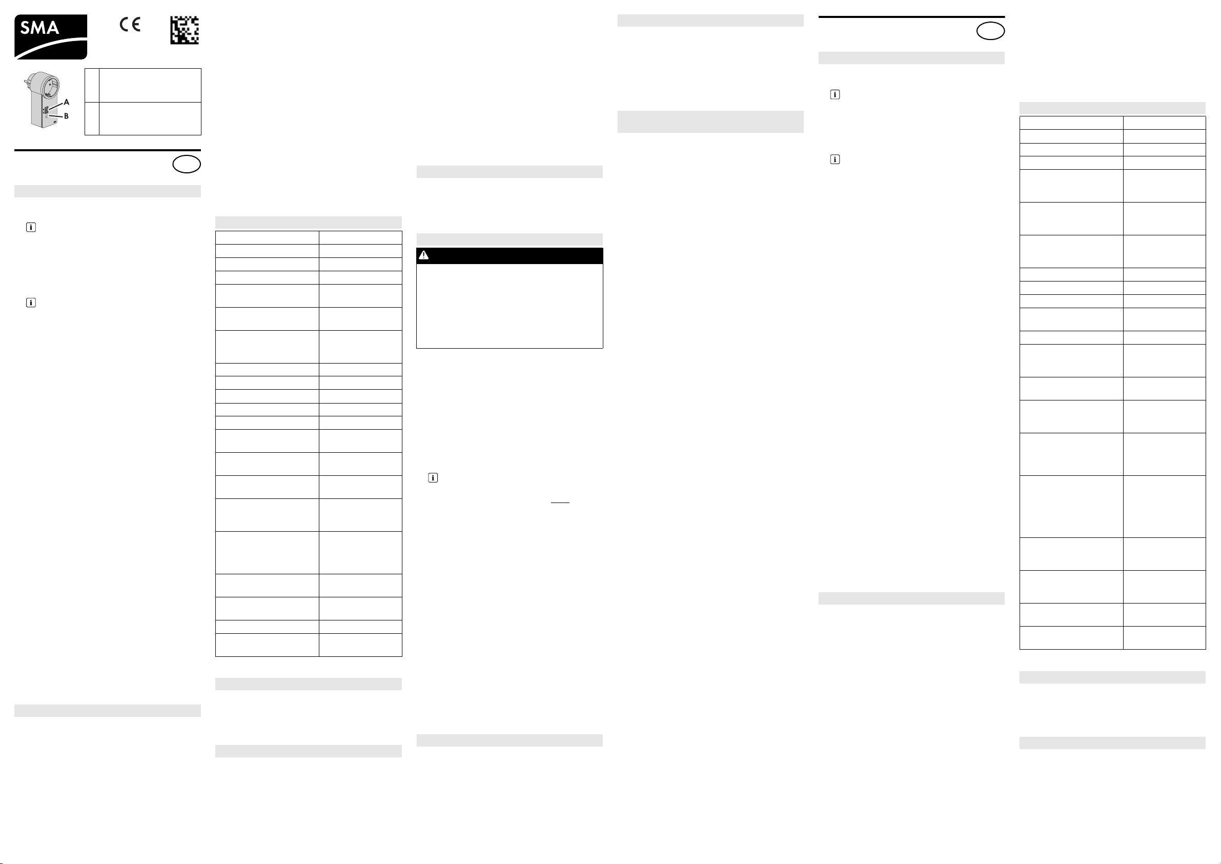
A LED display/
961.187
EN
ES
Indicador led/
Segnalazioni dei LED
BTouch key/
Tecla del sensor/
Tasto sensore
SMA Radio-Controlled Socket
with BLUETOOTH
Installation manual
®
Wireless Technology
Intended Use
The SMA radio-controlled socket is
1. an accessory to the Sunny Home Manager.
Control via Sunny Home Manager
For instructions on how to control the SMA
radio-controlled socket via the
Sunny Home Manager, refer to the manuals of
the Sunny Home Manager only.
®
2. a repeater for devices with SMA BLUETOOTH
Wireless Technology.
Use as a repeater
This document exclusively applies to the
use of the SMA radio-controlled socket as
a repeater.
The SMA radio-controlled socket must only be used in
accordance with this document or the manuals for the
Sunny Home Manager. Any other use may result in
personal injury or property damage.
Any use of the product other than that described in the
Intended Use section does not qualify as appropriate.
It is prohibited to make modifications that are not approved by SMA Solar Technology AG.
This document is valid for device type "BT-SOCKET10" as of firmware version 1.00.0.R (see type label).
This document is intended for end users and skilled
persons. Some of the tasks described in this document
may only be performed by skilled persons with the
appropriate qualifications. These tasks are identified
by an information note. Skilled persons must have the
following qualifications:
• Training in the installation and commissioning of
electrical devices.
• Knowledge of the applicable standards and
guidelines
The enclosed documentation is an integral part of this
product.
• The documentation must be read, observed and
always kept in a convenient place for future
reference.
The SMA radio-controlled socket is approved for the
use in all EU member states. The SMA radio-controlled
socket is designed for indoor use only.
• Only connect the SMA radio-controlled socket to
easily accessible outlets.
• Only connect the SMA radio-controlled socket to
properly installed socket-outlets with a grounding
contact.
• Only connect loads to the SMA radio-controlled
socket which are suitable for its voltage and power
range.
Safety Precautions
Danger to life due to electric shock
Lethal voltages are present in the conductive
components.
• Only use the SMA radio-controlled socket in a dry
environment.
• Avoid an y infl uence of mo istur e and dust a s well as
of solar irradiation and any other thermal irradiation.
• Only insert suitable plugs in the
SMA radio-controlled socket.
• Before cleaning, pull the SMA radio-controlled socket out of the socket-outlet, and clean with a dry
cloth only.
The SMA radio-controlled socket is equipped with a
relay with μ contact.
• Remove the SMA radio-controlled socket from the
electricity grid for safe disconnection.
Risk of inadvertent switching
The SMA radio-controlled socket used in conjunction
with the Sunny Home Manager can be switched via
the Sunny Portal (see manuals for the Sunny Home
Manager).
• Do not connect any loads. e.g. iron, to the SMA radio-controlled socket which could endanger persons or cause damage if inadvertently switched on.
Damage to the SMA Radio-Controlled Socket
If the SMA radio-controlled socket is not operated properly, it could be damaged.
• Do not operate SMA radio-controlled sockets
when they are plugged into each other.
Technical Data
Input voltage 100 V
to 230 V
AC
AC
Frequency 50 Hz / 60 Hz
Maximum current 16 A
Current consumption 0.25 W to 1.5 W
Max. switching power with
3,680 W
resistive load
Max. switching power with
600 W
lamp load
Max. switching power with
1,200 VA
inductive load
(cos φ > 0.65)
Ambient temperature − 5°C to +35°C
Relative humidity*
Degree of protection**
5% to 95%
IP20
Max. altitude above MSL 3,000 m
Pollution degree 2
Rated value of impulse with-
2,500 V
stand voltage
Operating mode of the elec-
S1
tronic switch
Type and/or circuitry of the
switch
Used in electric circuits for a
1 pole, 1 load (1-pole
disconnection)
Yes
inductive load with a power
factor of at least 0.6
Used in electric circuits for a
Yes
specified motor load with a
blocked rotor and a power
factor of at least 0.6
Comparative figure for proof
PTI 175
tracking index
Glow wire test (GWT) tem-
850°C
perature
Forced cooling required No
Installed protective devices
No
present
* non-condensing
** in accordance with IEC 60529
Scope of Delivery
Check the delivery for completeness and any visible
external damage.
• 1 x SMA radio-controlled socket
• 1 x installation manual
• 1 x supplementary sheet
LED States
Upper horizontal LED:
• Glowing green: SMA radio-controlled socket is
switched on. Load can draw electricity.
• Glowing orange: SMA radio-controlled socket is
switched off. Load cannot draw electricity.
• Glowing red: system is in the start-up or update
phase. Do not pull the SMA radio-controlled
socket out of the socket-outlet. Otherwise, the
SMA radio-controlled socket could be damaged.
Lower horizontal LED:
• Glowing blue: good SMA BLUETOOTH connection
• Flashing blue: critical SMA BLUETOOTH connection
Vertical LEDs:
• Glowing green: touch key is ready for operation.
Establishing the default settings is possible
(see Section "Establishing the default settings").
• Flashing green: SMA radio-controlled socket is
initializing.
Requirements for the Installation Site
☐ Socket-outlet is located in a suitable position
between devices with critical signal quality.
☐ A minimum distance of 1m to devices using the 2.4
GHz frequency band (e.g. WLAN devices,
microwave ovens) is observed.
Commissioning
DANGER
Risk of lethal electric shock when touching
conductive components of the inverter
• Only skilled persons may work on the
inverter.
• Prior to performing any work on the inverter,
disconnect the inverter from any voltage
sources on the AC and DC sides (see inverter
installation manual).
1. Decommission the plant (see manuals of the
connected devices). This will ensure that the
SMA radio-controlled socket is integrated into the
SMA BLUETOOTH network at the point where the
dead zone occurs.
2. Insert the SMA radio-controlled socket into the socket-outlet.
☑ Upper horizontal LED (A) glows red for approx.
10 seconds.
3. As soon as the LED display shows "0", tap the
touch key (B) several times until the NetID of the
plant is displayed.
The same NetID for all devices
All SMA devices communicating via
BLUETOOTH must be set to the same
NetID.
The NetID can be a number from 2 to 9 or a letter from A to F.
4. Wait five seconds to adopt the NetID.
5. Recommission the plant (see the manuals of the
connected devices).
☑ Wait approx. two minutes until the lower
horizontal LED is glowing blue.
✖ If the lower horizontal LED is flashing blue:
SMA BLUETOOTH connection is critical.
• If possible, move to another installation site.
• If no other installation location is possible, use
an additional SMA radio-controlled socket or
an SMA BLUETOOTH Repeater.
✖ If the lower horizontal LED is off:
No SMA BLUETOOTH connection.
• Make sure that the SMA radio-controlled
socket and the plant devices are se t to the same
NetID (see Section "Change NetID").
• If possible, move to another installation site.
• If no other installation location is possible, use
an additional SMA radio-controlled socket or
an SMA BLUETOOTH Repeater.
Changing the NetID
1. Keep the touch key pressed until the LED display
shows the previously set NetID.
2. Tap the touch key several times until the desired
NetID is displayed.
3. Wait five seconds to adopt the NetID.
Establishing the Default Settings
1. Pull out and reinsert the SMA radio-controlled socket into the socket-outlet.
☑ Upper horizontal LED glows red for approximately
ten seconds.
2. As soon as the vertical LEDs are glowing green,
keep the touch key pressed until the upper horizontal LED is glowing red.
☑ LED display shows "0".
Switching on/off the SMA radio-controlled
socket
1. To switch on the SMA radio-controlled socket, tap
the touch key.
☑ Upper horizontal LED is glowing green.
The SMA radio-controlled socket audibly
switches to the selected operating mode.
2. To switch off the SMA radio-controlled socket, tap
the touch key.
☑ Upper horizontal LED is glowing orange.
The SMA radio-controlled socket audibly switches
to the selected operating mode.
Enchufe inalámbrico de SMA
con BLUETOOTH® Wireless Technology
Instrucciones de instalación
Uso previsto
El enchufe inalámbrico de SMA:
1. Es un accesorio del Sunny Home Manager.
Control del Sunny Home Manager
Para el control del Sunny Home Manager tenga en cuenta únicamente las instrucciones del
Sunny Home Manager.
2. Es un repetidor entre los equipos con
SMA BLUETOOTH
®
Wireless Technology.
Utilización como repetidor (“repeater”)
Este documento sirve exclusivamente
para la aplicación del enchufe
inalámbrico de SMA como repetidor.
Utilice el enchufe inalámbrico de SMA únicamente
siguiendo las indicaciones de este documento o las
instrucciones del Sunny Home Manager. Otros usos
del producto pueden causar lesiones al usuario o
daños materiales.
Cualquier uso del producto distinto al descrito en el
uso previsto se considerará uso inadecuado.
Quedan
prohibidas las modificaciones o incorporaciones no
autorizadas.
Este documento es válido para el tipo de equipo
“BT-SOCKET-10” a partir de la versión de firmware
1.00.00.R (consulte la placa de características).
Este docu mento está dirigido a usuar ios finales y espe cialistas. Algunas de las actividades descritas en este
documento solo podrá llevarlas a cabo personal
especializado con la cualificación correspondiente.
Estas actividades están señalizadas mediante una
indicación. El personal especializado debe contar
con esta cualificación:
• Formación para la instalación y puesta en servicio
de equipos eléctricos
• Conocimientos de las normativas y directrices
aplicables
La documentación adjunta es parte integrante del
producto.
• Lea y tenga en cuenta esta documentación y
consérvela en un lugar de fácil acceso en todo
momento.
El enchufe inalámbrico de SMA está homologado
para todos los países de la UE. El enchufe inalámbrico
de SMA es apto únicamente para su uso en interiores.
• Conecte el enchufe inalámbrico de SMA solamente en tomas de pared fácilmente accesibles.
• Conecte el enchufe inalámbrico de SMA solamente en tomas de pared instaladas conforme a la
normativa y con toma de tierra.
• Al enchufe inalámbrico de SMA conecte
únicamente equipos consumidores adecuados
para el rango de tensión y de potencia del enchufe inalámbrico de SMA.
Indicaciones de seguridad
Peligro de muerte por descarga eléctrica
En los componentes conductores de tensión hay
tensiones eléctricas que pueden causar la muerte.
• Utilice el enchufe inalámbrico de SMA únicamente
en entornos secos.
• Evite la influencia de humedad y polvo así como la
radiación solar o térmica.
• Conecte en el enchufe inalámbrico de SMA
únicamente tomas adecuadas.
• Desenchufe el enchufe inalámbrico de SMA de la
toma de la pared antes de limpiarlo y límpielo solo
con un paño seco.
El enchufe inalámbrico de SMA tiene un relé con un
contacto μ.
• Para llevar a cabo una desconexión de la red
pública de manera segura, retire el enchufe
inalámbrico de SMA de la toma de pared.
Peligro por conexión involuntaria
El enchufe inalámbrico de SMA puede accionarse
conectado con un Sunny Home Manager a través del
Sunny Portal (consulte las instrucciones del
Sunny Home Manager).
• No conecte al enchufe inalámbrico de SMA
ningún equipo consumidor que pueda provocar
daños personales o materiales por una conexión
involuntaria (p. ej., la plancha).
Daños en el enchufe inalámbrico de SMA
Si se lleva a cabo un uso inadecuado, el enchufe
inalámbrico de SMA podría dañarse.
• No conecte los enchufes inalámbricos de SMA
entre sí.
Datos técnicos
Tensión de entrada 100 V
…230V
CA
CA
Frecuencia 50 Hz/60 Hz
Corriente máxima 16 A
Consumo de electricidad 0,25 W … 1,5 W
Potencia máxima de
3 680 W
conmutación con carga resistiva
Potencia máxima de
600 W
conmutación con carga de
lámpara
Potencia máxima de
1 200 VA
conmutación con carga inductiva (cos φ > 0,65)
Temperatura ambiente − 5 °C … +35 °C
Humedad relativa del aire*
Tipo de protección**
Altitud máx. sobre el nivel
5% … 95%
IP20
3 000 m
del mar
Índice de contaminación 2
Valor de medición de la
2 500 V
tensión de choque soportable
Tipo de funcionamiento del
S1
interruptor electrónico
Tipo y/o conmutación del interruptor
Un polo, una carga
(desconexión unipo-
lar)
Aplicación en circuitos
Sí
eléctricos para una carga inductiva con un factor de potencia de al menos 0,6
Aplicación en circuitos
Sí
eléctricos para una carga
del motor determinada con
un rot or b loq uea do y con un
factor de potencia de al
menos 0,6
Índice de resistencia a la
PTI 175
formación de caminos conductores
Temperatura de la prueba
850 °C
del hilo incandescente
(GWT)
Refrigeración forzada nece-
No
saria
Disponible dispositivo de
No
protección integrado
* Sin condensación
** Según IEC 60529
Contenido de la entrega
Compruebe que el contenido de la entrega esté
completo y que no presente daños externos visibles.
• Un enchufe inalámbrico de SMA
• Unas instrucciones de instalación
• Un suplemento
Estados de led
Led superior horizontal:
• Verde encendido: el enchufe inalámbrico de SMA
está conectado. El equipo consumidor puede
tomar corriente.
• Naranja encendido: el enchufe inalámbrico de
SMA está desconectado. El equipo consumidor no
puede tomar corriente.
BTFSD-IA-en-es-it-13 | Version / Versión / Versione 1.3 SMA Solar Technology AG
Page 2
• Rojo encendido: el sistema está arrancando o se
IT
encuentra en un proceso de actualización. No
quite el enchufe inalámbrico de SMA de la toma
de pared. En caso contrario, el enchufe
inalámbrico de SMA podría dañarse.
Led inferior horizontal:
• Azul encendido: buena conexión SMA BLUETOOTH
• Azul intermitente: conexión SMA BLUETOOTH
crítica
Led perpendiculares:
• Verde encendido: la tecla del sensor está operativa. Es posible adoptar la configuración estándar
(consulte el apartado ”Adoptar la configuración
estándar”).
• Verde intermitente: el enchufe inalámbrico de
SMA se está arrancando.
Requisitos del lugar de instalación
☐ El enchufe tiene que encontrarse en un lugar
adecuado entre los equipos con una calidad de la
conexión crítica.
☐ Mantenga una distancia mínima de 1 m de
dispositivos que utilicen la banda de frecuencia de
2,4 GHz (como equipos WLAN u hornos
microondas).
Puesta en servicio
PELIGRO
Peligro de muerte por electrocución por las
piezas conductoras de tensión del inversor
• Los trabajos en el inversor deben realizarlos
únicamente especialistas.
• Antes de realizar cualquier trabajo en el
inversor, desconéctelo del lado de la CA y la
CC (consulte las instrucciones de instalación
del inversor).
1. Detenga el funcionamiento de la instalación (consulte las instrucciones de los equipos conectados).
De este modo se asegura de que el enchufe
inalámbrico de SMA quede inmediatamente integrado en la red SMA BLUETOOTH en la que existe un área sin recepción.
2. Conecte el enchufe inalámbrico de SMA a la toma
de pared.
☑ El led superior horizontal (A) se ilumina en rojo
durante 10 segundos aproximadamente.
3. Cuando el indicador led muestre ”0”, pulse la
tecla del sensor (B) las veces necesarias hasta que
apa-rezca la NetID de la instalación.
Misma NetID en todos los equipos
To dos los equ ipos de S MA q ue s e co muni que n
a través de BLUETOOTH deben ser
configurados con la misma
NetID. La NetID
puede ser un valor del 2 al 9 o de la A a la F.
4. Para adoptar la NetID, espere 5 segundos.
5. Vuelva a poner en funcionamiento la instalación (con
sulte las instrucciones de los equipos conectados).
☑ Espere 2 minutos aproximadamente hasta que el
led inferior horizontal se ilumine en azul.
✖ ¿El led inferior horizontal parpadea en azul?
La conexión SMA BLUETOOTH es crítica.
• A ser posible, elija otro lugar de instalación.
• Si no es posible utilizar otro lugar de instalación,
emplee un enchufe inalámbrico de SMA adicio
nal o un SMA BLUETOOTH Repeater.
✖ ¿Está apagado el led inferior horizontal?
No existe conexión SMA BLUETOOTH.
• Asegúrese de que en el enchufe inalámbrico
de SMA y en los equipos de la instalación esté
configurada la misma NetID (consulte el apartado ”Modificar la NetID”).
• A ser posible, elija otro lugar de instalación.
• Si no es posible utilizar otro lugar de instalación,
emplee un enchufe inalámbrico de SMA adicio
nal o un SMA BLUETOOTH Repeater.
Modificar la NetID
1. Mantenga pulsada la tecla del sensor hasta que el
indicador led muestre la última NetID configurada.
2. Pulse la tecla del sensor las veces necesarias hasta
que aparezca la NetID deseada.
3. Para adoptar la NetID, espere 5 segundos.
Adoptar la configuración estándar
1. Desconecte el enchufe inalámbrico de SMA de la
toma de pared y vuelva a enchufarlo de nuevo.
☑ El led superior horizontal se ilumina en rojo
durante 10 segundos aproximadamente.
2. Cuando los led verticales se iluminen en verde,
mantenga pulsada la tecla del sensor hasta que el
sensor superior horizontal se ilumine en rojo.
☑ El indicador led muestra ”0”.
Conexión y desconexión del enchufe inalámbrico de SMA
1. Para conectar el enchufe inalámbrico de SMA,
pulse la tecla del sensor.
☑ El led superior horizontal se ilumina en verde.
El enchufe inalámbrico de SMA cambia de una
manera audible al modo de funcionamiento
seleccionado.
2. Para desconectar el enchufe inalámbrico de SMA,
pulse la tecla del sensor.
☑ El led superior horizontal se ilumina en naranja.
El enchufe inalámbrico de SMA cambia de una
manera audible al modo de funcionamiento
seleccionado.
Eliminación del equipo
Elimine el enchufe inalámbrico de SMA conforme a
las disposiciones sobre eliminación de residuos
electrónicos vigentes en el lugar de instalación.
-
-
-
Presa radio SMA
con BLUETOOTH
Istruzioni per l'installazione
®
Wireless Technology
Utilizzo conforme
La presa radio SMA è
1. un accessorio di Sunny Home Manager.
Gestione tramite Sunny Home Manager
Per la gestione tramite Sunny Home Manager,
fare riferimento esclusivamente alle istruzioni di
Sunny Home Manager.
2. un repeater tra apparecchi con SMA
BLUETOOTH
®
Wireless Technology.
Utilizzo come repeater
Il presente documento è valido esclusiva-
mente per l'utilizzo della presa radio SMA
come repeater.
La presa radio SMA deve essere utilizzata esclusivamente secondo quanto indicato nel presente documento e nelle istruzioni di Sunny Home Manager. Utilizzi diversi possono provocare danni a persone o cose. Non è consentito alcun utilizzo del prodotto
diverso da quanto specificato nella sezione Utilizzo
conforme. È vietato apportare modifiche o trasformazioni non autorizzate. Il presente documento è valido
per il tipo di apparec-chio “BT-SOCKET-10“ a partire
dalla ver sione firmw are 1.00.0.R. (v. targhetta di iden tificazione). Il presente documento è destinato agli utenti finali e tecnici specializzati. Alcune delle
operazioni descritte nel presente documento devono
essere eseguite esclusivamente da tecnici specializzati in possesso di relativa qualifica. Dette operazioni
sono contrassegnate da una nota. I tecnici specializzati devono disporre delle seguenti qualifiche:
• Formazione relativa all'installazione e alla messa
in servizio di apparecchi elettrici
• Conoscenza delle norme e delle direttive vigenti
La documentazione in allegato è parte integrante del
prodotto.
• Leggere e rispettare la documentazione, che deve
risultare accessibile in qualsiasi momento.
La presa radio SMA è omologata per l'impiego in stati
membri dell'UE. La presa radio SMA è idonea esclusiva-mente per l'impiego in ambienti interni.
• Collegare la presa radio SMA solo a prese facilmente accessibili.
• Collegare la presa radio SMA solo a prese a
norma con contatto di protezione.
• Collegare alla presa radio SMA solo utenze
adeguate al suo campo di tensione e potenza.
Avvertenze di sicurezza
Pericolo di morte per scossa elettrica
Nei componenti conduttori di tensione sono presenti
tensioni pericolose.
• Utilizzare la presa radio SMA solo in ambienti asciutti.
• Evitare la penetrazione di umidità e polvere
nonché l’esposizione ai raggi del sole o di altra
fonte di calore.
• Inserire nella presa radio SMA solo spine adatte.
• Per la pulizia rimuovere per prima cosa la presa
radio SMA dalla presa e utilizzare poi solo un
panno asciutto.
La presa radio SMA contiene un relè con contatto μ.
• Per una separazione sicura dalla rete pubblica
rimuovere la presa radio SMA dalla presa.
Pericolo da attivazione involontaria
La presa radio SMA può essere attivata in abbinamento a Sunny Home Manager tramite Sunny Portal
(vedere le istruzioni di Sunny Home Manager).
• Non collegare alla presa radio SMA utilizzatori la
cui attivazione involontaria possa costituire un pericolo per persone o causare danni, ad es. ferro da
stiro.
Danneggiamento della presa radio SMA
Un funzionamento improprio può danneggiare la
presa radio SMA.
• Non utilizzare le prese radio SMA collegate tra
loro.
Dati tecnici
Tensione d’ingresso 100 V
… 230 V
CA
CA
Frequenza 50 Hz / 60 Hz
Corrente massima 16 A
Assorbimento di corrente 0,25 W … 1,5 W
Potenza di commutazione
3 680 W
max con carico ohmico
Potenza di commutazione
600 W
max con carico lampade
Potenza di commutazione
1200VA
max con carico induttivo
(cos φ > 0,65)
Temperatura ambiente − 5 °C … +35 °C
Umidità relativa*
Grado di protezione**
5% … 95%
IP20
Altitudine max s.l.m. 3 000 m
Grado di inquinamento 2
Valore di misurazione della
2 500 V
tensione impulsiva massima
Modalità di funzionamento
S1
dell’interruttore elettronico
Tipo e/o commutazione
dell’interruttore
Unipolare, carico sin-
golo (disinserzione
unipolare)
Impiego su circuiti elettrici
Sì
per un carico induttivo con
un fattore di potenza pari ad
almeno 0,6
Impiego su circuiti elettrici
Sì
per un carico motore determinato con rotore bloccato e
un fattore di potenza pari ad
almeno 0,6
Indice di riferimento forma-
PTI 175
zione di fuga
Temperatura test filamento
850 °C
incandescente (GWT)
Necessario raffreddamento
No
forzato
Dispositivo di protezione in-
No
tegrato presente
* Non condensante
** Secondo IEC 60529
Contenuto della fornitura
Controllare che la fornitura sia completa e non
presenti danni visibili all'esterno.
• 1 presa radio SMA
• 1 manuale di istruzioni per l'installazione
• 1 foglio aggiuntivo
Stati LED
LED orizzontale superiore:
• Verde: la presa radio SMA è attivata. L'utenza può
ricevere corrente.
• Arancione: la presa radio SMA è disattivata.
L'utenza non può ricevere corrente.
• Rosso: avvio del sistema o aggiornamento in corso. Non estrarre la presa radio SMA dalla presa.
In caso contrario la presa radio SMA può subire
danni.
LED orizzontale inferiore:
• Blu: collegamento SMA BLUETOOTH regolare
• Blu lampeggiante: collegamento SMA BLUETOOTH critico
LED verticali:
• Verdi: il tasto sensore è operativo. È possibile definire impostazioni standard (vedere paragrafo "de
finizione impostazioni standard").
• Verdi lampeggianti: la presa radio SMA viene inizializzata.
Requisiti del luogo di installazione
☐ La presa si trova in un luogo adatto tra i dispositivi
con qualità di connessione critica.
☐ Mantenere una distanza minima di 1 m dagli
apparecchi che utilizzano la banda di frequenza
a 2,4 GHz (ad es. apparecchi WLAN o forni
microonde).
Messa in servizio
PERICOLO
Pericolo di morte per scossa elettrica dovuto ai componenti sotto tensione dell'inverter.
• Sull'inverter devono operare solo tecnici
specializzati.
• Prima di eseguire qualsiasi intervento
sull'inverter, disinserire l'inverter sul lato CA e
CC (vedere le istruzioni per l'installazione
dell'inverter).
1. Disattivare l'impianto (vedere le istruzioni degli
apparecchi collegati). In questo modo ci si assicura che la presa radio SMA sia inserita nel punto
della rete SMA BLUETOOTH dove sussiste il problema di connessione.
2. Inserire la presa radio SMA nella presa.
☑ Il LED orizzontale superiore (A) si accende per
circa 10 secondi con luce rossa.
3. Quando l'indicatore LED mostra "0", premere più
volte il tasto sensore (B) finché viene visualizzato il
NetID dell'impianto.
Stesso NetID su tutti gli apparecchi
Tutti gli apparecchi SMA che comunicano tramite BLUETOOTH devono essere impostati sullo stesso
NetID. Il NetID può essere un
carattere da 2 a 9 o da A a F.
4. Attendere 5 secondi per acquisire il NetID.
5. Rimettere in funzione l'impianto (vedere le istruzioni degli apparecchi collegati).
☑ Attendere circa 2 minuti finché il LED orizzontale
inferiore si accende con luce blu.
✖ Il LED orizzontale inferiore lampeggia con luce
blu?
La connessione SMA BLUETOOTH è critica.
• Se possibile, scegliere un altro luogo di installa-
zione.
• Se ciò non è possibile, utilizzare una presa
radio SMA aggiuntiva o uno SMA BLUETOOTH Repeater.
✖ Il LED orizzontale inferiore è spento?
Nessuna connessione SMA BLUETOOTH.
• Assicurarsi che nella presa radio SMA e negli
apparecchi dell'impianto sia impostato lo
stesso NetID (vedere paragrafo "Modifica del
NetID").
• Se possibile, scegliere un altro luogo di installa-
zione.
• Se ciò non è possibile, utilizzare una presa
radio SMA aggiuntiva o uno SMA BLUETOOTH Repeater.
Modifica del NetID
1. Tenere premuto il tasto sensore finché l'indicatore
LED mostra l'ultimo NetID impostato.
2. Premere più volte il tasto sensore fino a visualizzare il NetID desiderato.
3. Attendere 5 secondi per acquisire il NetID.
Definizione delle impostazioni standard
1. Estrarre la presa radio SMA dalla presa, quindi
reinserirla.
☑ Il LED orizzontale inferiore si accende per circa
10 secondi con luce rossa.
-
2. Non appena i LED verticali si accendono con luce
verde, tenere premuto il tasto sensore finché il LED
orizzontale inferiore si accende con luce rossa.
☑ L'indicatore LED mostra "0".
Attivazione/disattivazione della presa radio
SMA
1. Toccare il tasto sensore per attivare la presa radio
SMA.
☑ Il LED orizzontale superiore si accende con luce
verde. Si può sentire il passaggio della presa radio
SMA alla modalità operativa selezionata.
2. Toccare il tasto sensore per disattivare la presa
radio SMA.
☑ Il LED orizzontale superiore si accende con luce
arancione. Si può sentire il passaggio della presa
radio SMA alla modalità operativa selezionata.
Smaltimento
Smaltire la presa radio SMA secondo le norme per lo
smaltimento vigenti per gli apparecchi elettrici nel luogo di installazione.
BTFSD-IA-en-es-it-13 SMA Solar Technology AG
 Loading...