

Singer NP050101, NP050103 Service Manual
SINGER
INDUSTRIAL
PRODUCTS
Needle
Catalog
SERVICE
Positioner
Numbers
I.
MANUAL
for
the
SINGER
and
—
Underbed
NP050101
Thread
and
Trimmer
NP050103
'A Trade
Mark
ofThe
Fordetails,
Industrial Products Division, 30 Rockefeller Plaza, New York, N.Y. 10020
Singer
Company
call
your
Industrial
Copyright
All
Rights
Sales
©1967
Reserved
Office,
or write The
THE
INDUSTRIAL
by The Singer Company
Throughout
SINGER
the
World
Singer
Company,
PRODUCTS
COMPANY
DIVISION
Printed
in U.S.A.
TABLE
OF
CONTENTS
Paragraph
SECTION
SECTION
SECTION
Title
I -
GENERAL
1-1 PURPOSE 1
1-2
1-3
II -
2-1
2-2
2-3
2-4
2-5
2-6
2-7
2-8
2-9
2-10
III -
FEATURES 2
BASIC COMPONENTS 2
INSTALLATION
GENERAL INFORMATION 3
PREPARATION
POWER
OPERATING
SEWING
COMMUTATOR SENSOR 10
POSITIONER
TRIMMER
T
RIMMER
THREAD
OPERATION
INFORMATION
OF SEWING
TRANSMITTER
SWITCHES
HEAD
CONTROL
PACK
SOLENOID
WIPER
ASSEMBLY.
TABLE
CONSOLE
ASSEMBLY
Page
16
19
3
3
4
10
11
13
SECTION
SECTION
3-1
3-2
3-3
IV -
4-1
4-2
V -
5-1
GENERAL INFORMATION 20
PRE-OPERATING CHECKS 20
OPERATION 20
SERVICING
GENERAL
CLEANING INSTRUCTIONS 22
TROUBLESHOOTING
GENERAL
5-2 Needle Not
5-3
5-4
5-5
5-6
Faulty
Bobbin Thread
Needle
Needle
TrimmingorDouble
Thread
Thread Pulls
AND
INFORMATION
INFORMATION
ADJUSTMENTS
Positioning
Cut
Too
Cut
Too Short 25
Out
Properly
Short
TriggeringofSolenoid
of
Needle
Assembly
...
22
24
24
24
24
25
LIST
OF
ILLUSTRATIONS
Figure
1 S
2 Sewing Table
3 Operating Switches 5
4
5 Foot
6
7 Slo-Sew Switch 8
8 Operating
9
lOA
&B Positioner Control Console 12
1lA & B
nC
IID
12 Setting of
13
14A
&B
15
16 Operating Controls
inger
Heel
Knee
Commutator
Trim
Trim
Thread
Trimmer
Trimmer
Thread Wiper J9
Needle
Sewing
Switch
Trim
Trim
Pack Thread Picker Installation 14
Pack Thread Picker Installation 15
Picker
Solenoid
Solenoid
Positioner
Machine
Top
Installation 6
Switch Installation.• 7
Switch Installation 8
Switches
Sensor
Assembly
Adjustment
Trimmer
Knife
Assembly
Adjustments
Title
and
and
Underbed
Wiring
Procedure
Trimmer
Data
Equipped
Page
1
4
9
11
15
16
17
18
21
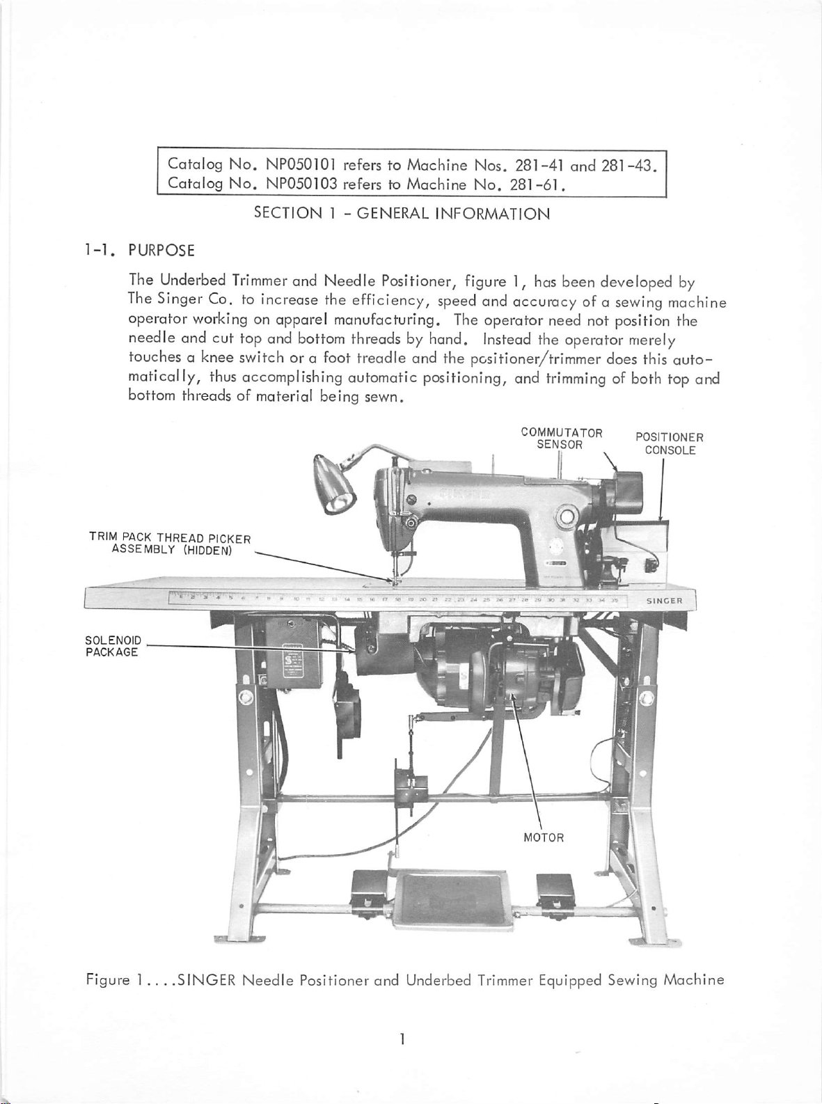
Catalog
Catalog
No,
NP050101 refers to
No.
NP050103
refers to
Machine
Machine
Nos, 281-41
No.
281-61.
and
281-43.
PURPOSE
The
Underbed
The
Singer
operator
needle
SECTION
Trimmer
Co.toIncrease
working
and
on apparel manufacturing.
cut
top
and
and
bottom
1 -
GENERAL
Needle
the
Positioner,
efficiency,
threadsbyhand.
INFORMATION
figure1,has
speed
The
and
accuracy
operator
Instead
need
the
been
developed
ofa
not position the
operator
touches a knee switch or a foot treadle and the positioner/trimmer does this auto
matically,
bottom threads of material being sewn.
TRIM
PACK
ASSEMBLY
THREAD
thus
PICKER
(HIDDEN)
accomplishing
automatic
positioning,
and
trimmingofboth
COMMUTATOR
SFWCJOR
sewing
merely
POSITIONER
CONSOLE
by
machine
top
and
SOLENOID
PACKAGE
y
Figure 1... .SINGER Needle Positioner and Underbed
Trimmer
Equipped Sewing Machine
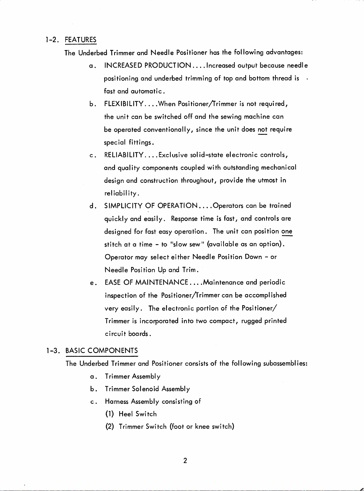
1-2.
FEATURES
The Underbed
a.
b.
c.
d.
Trimmer
INCREASED
and
Needle
PRODUCTION
Positioner has the following advantages:
....
Increased output because needle
positioning and underbed trimming of top and bottom thread is •
fast
and
automatic.
FLEXIBILITY....When Positioner/Trimmer is not required,
the
unit
con be switched
off
and
the
sewing machine
can
be operated conventionally, since the unit does not require
special fittings.
RELIABILITY.
...
Exclusive
solid-state
electronic
controls,
and quality components coupled with outstanding mechanical
design and construction throughout, provide the utmost in
reliability.
SIMPLICITY
quickly and easily.
OF OPERATION... .Operators con be trained
Response
time is fast, and controls are
designed for fast easy operation. The unit can position one
1-3.
stitch at a time - to "slowsew" (available as an option).
Operator may select either Needle Position
Needle
e.
EASE
inspection of the
very easily.
Trimmer
circuit
BASIC
The Underbed Trimmer and Positioner consists of the following subossemblies:
COMPONENTS
a.
Trimmer Assembly
b.
Trimmer Solenoid Assembly
c.
Harness Assembly consisting of
(1) Heel Switch
Position
Up
and Trim.
OF MAINTENANCE... .Maintenance and periodic
Positioner/Trimmer
The
electronic portion of the Positioner/
can be
is incorporated into two compact, rugged printed
boards.
Down
- or
accomplished
(2) Trimmer Switch (foot or knee switch)
(3)
Slow
Sew
Switch (optional)
d.
Needle
e.
Commutator Sensor Assembly
f.
Thread
Positioner Assembly
Wiper
Assembly
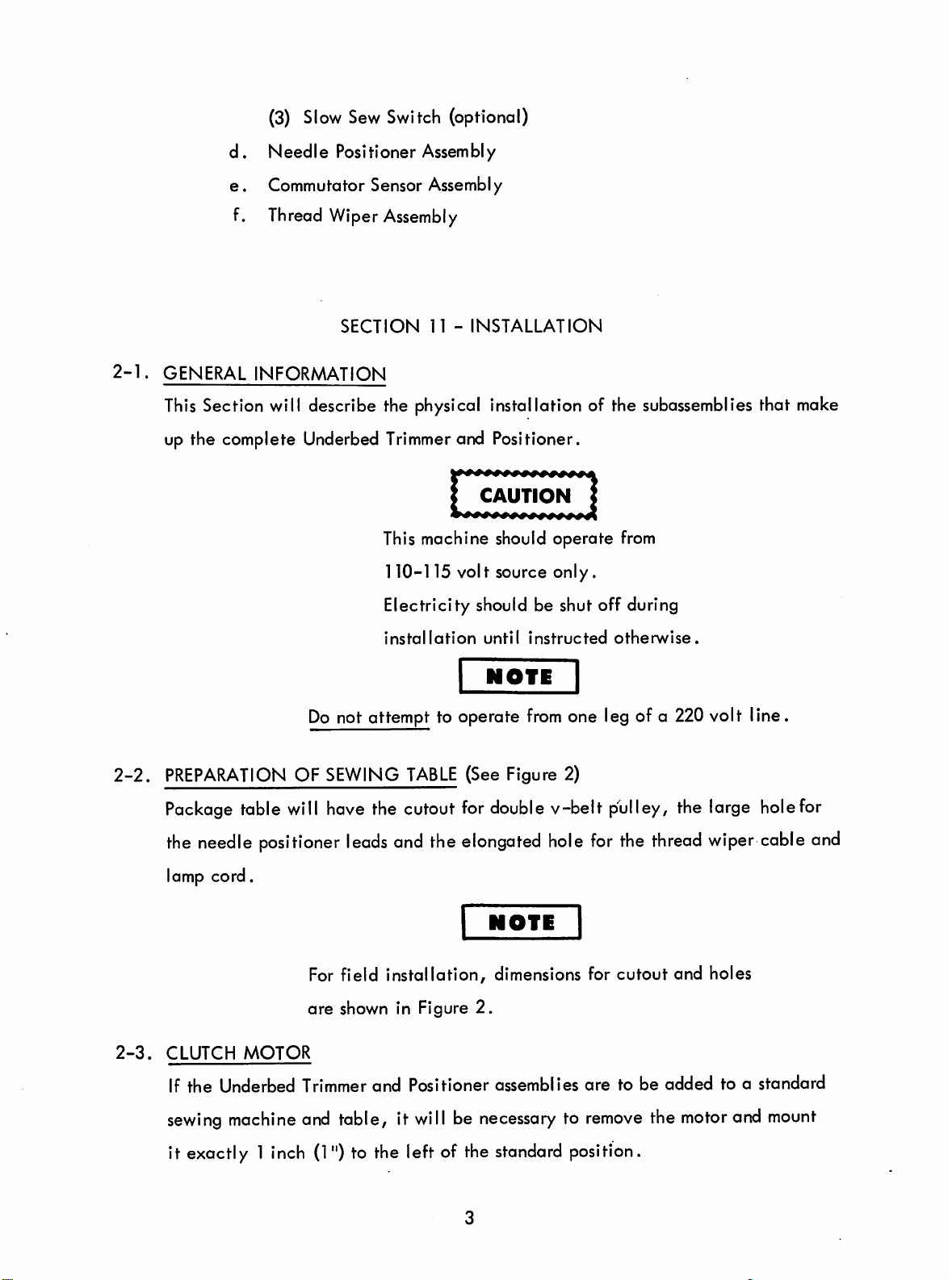
2-1.
2-2.
SECTION
GENERAL
This
Section will describe the physical installation of the subossemblies that
INFORMATION
up the complete Underbed
n -
INSTALLATION
Trimmer
This machine should operate from
110-115 volt source
and Positioner.
CAUTION
only.
:
Electricity should be shut off during
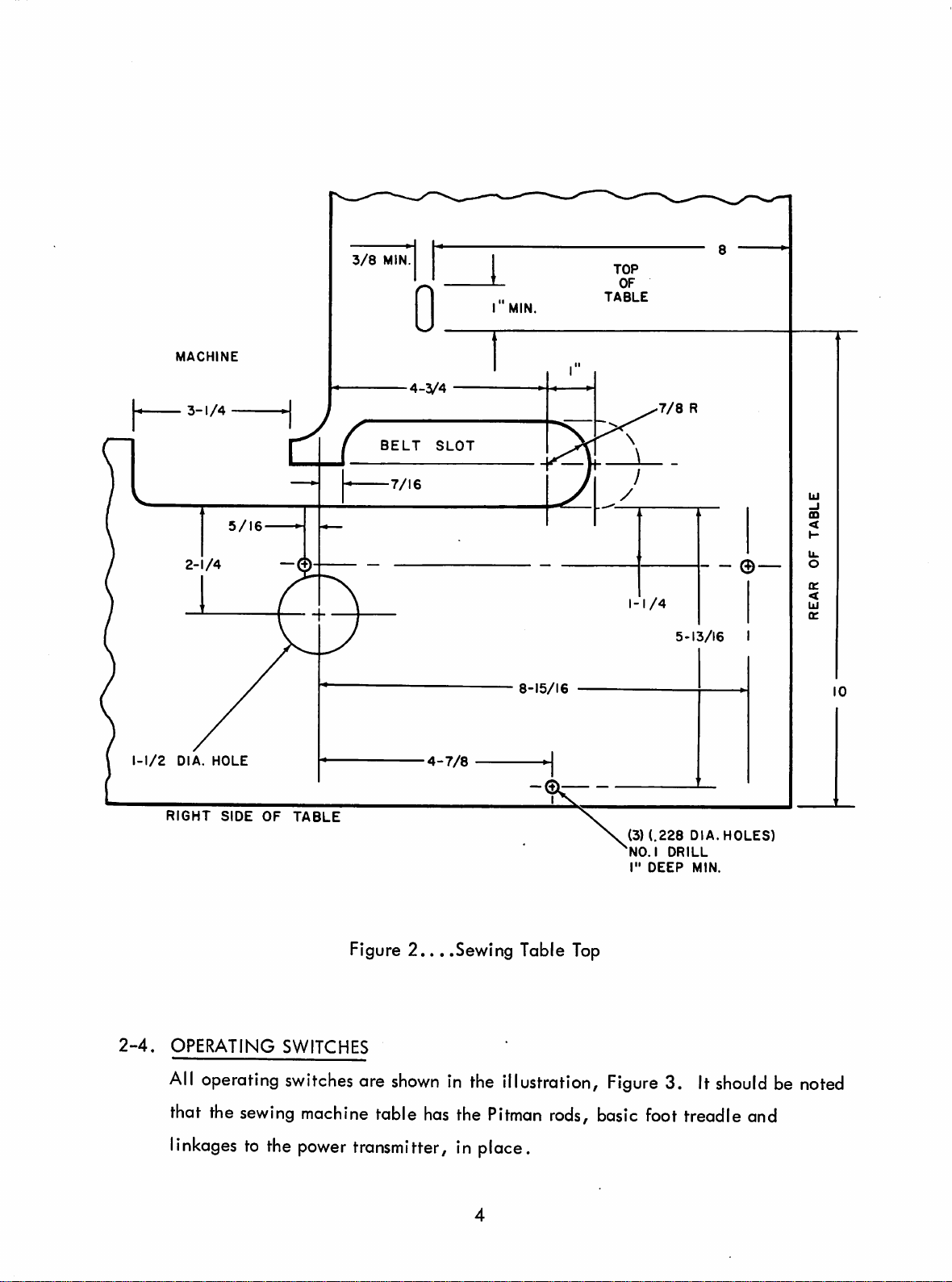
PREPARATION
installation
Do
not attempt to operate
OF SEWING
TABLE
until
instructed
NOfE
from
(See Figure 2)
otherwise.
one leg of a 220 volt line.
make
Package table will have the cutout for double v-belt pulley, the large holefor
the
2-3.
needle
lamp cord.
CLUTCH
If the Underbed Trimmer and Positioner assemblies
sewing
positioner
MOTOR
machine
leads
For field
are
shown in Figure
and
table, it
and the elongated
NOTE
installation,
will
dimensions for
2.
be
necessarytoremove
hole
for
the
thread
cutout
are
to be added to a standard
the
it exactly 1 inch (1") to the left of the standard position.
wiper
and holes
motor
and
cable
mount
and
MACH
3-1/4
NE
3/8
MIN
TABLE
1-1/2
DIA.
RIGHT
HOLE
SIDE
OF
TABLE
BELT
SLOT
4-7/8
8-15/16
5-13/16
(3)
(.228
NO.IDRILL
I"
DEEP
DIA.
MIN.
I
HOLES)
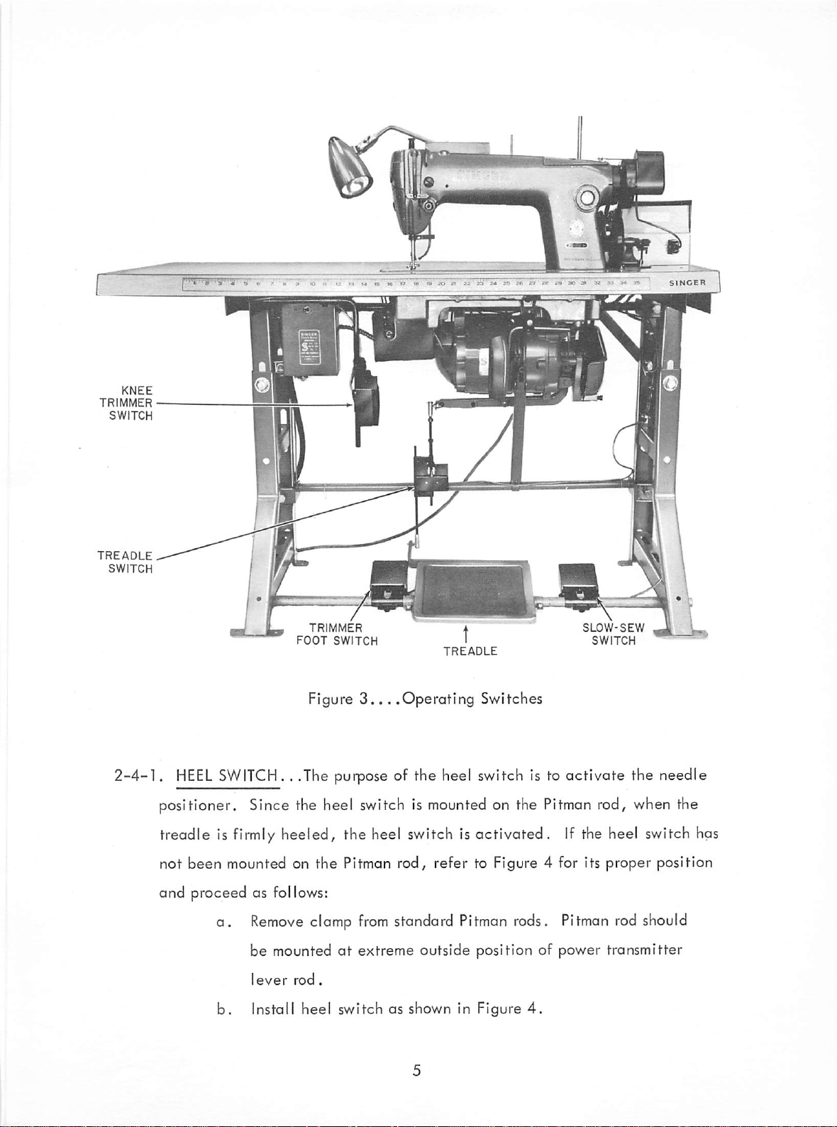
2-4.
OPERATING
All
operofing
that the
sewing
linkages to the
Figure
SWITCHES
switches
ore
machine table
power
transmitter, in place.
2,...Sewing
shown
in the illustration.
has
the
Table
Pitman
Top
Figure
rods,
basic foot treadle and
3. It
should
be
noted
KNEE
TRIMMER
SWITCH
TREADLE
SWITCH
2-4-1.
TRIMMER
FOOT
SWITCH
HEEL
SWITCH.
Figure
. .The purpose of the heel switch is to activate the needle
3...
.OperaHng Switches
positioner. Since the heel switch is
TREADLE
mounted
on the Pitman rod, when the
SLOW-SEW
SWITCH
treadle is firmly heeled, the heel switch is activated. If the heel switch has
not
been
mounted on
and proceed as follows:
a.
Remove
be mountedatextreme outside position of power transmitter
b.
Install
the
clamp
heel
Pitman
from
switch
rod,
refer to Figure 4 for its proper position
standard Pitman rods. Pitman rod should
as shown in Figure
4.

2-4-2.
The
TRIM
Trim
SWITCH
Switch
(See Figure 3)
isa
universal
type that can be
used
either for knee operation,
mounted
treadle.
If the
trim
under table or as a foot switch
a.
Foot
Trim
Switch-mounted
treadle is firmly heeled and the foot
when
slipped on treadle
to
the
left
trim
of
the
treadle.
switch is depressed,
the machine will position up and trim.
b.
Knee
Trim
by
the
Switch-mounted
knee,
the
machine
under
will
positionupand
the
table.
When
trim.
switch has not been installed on the sewing table proceed as
SCREW
PITMAN
(TO
ADJUST
ROD
MOTOR)
rod
to left of
When
activated
"a"
set
COLLAR
HEEL
adjust"
follows:
screw
PRESSURE
s
PITMAN
(TO
ROD
TREADLE)
Figure
4...
.Heel
Switch Installation
 Loading...