


 Loading...
SIM2 Multimedia
M.150
User Guide

Contents
3Important information
About this User Guide Safety
3D Content Environment Notice
7Chapter 1: Introduction
Key Features and Benefits System Components Optional Accessories
9Chapter 2: Overview
Remote Control Projector Keypad Connections
3D IR Emitter
3D Glasses
14Chapter 3: Installation
Location Mounting Connections
Switching On and Off
19Chapter 4: Operation
Viewing 3D Content 3D Menu
Input Menu Main Menu Picture Image Setup Menu Memories Info
Quick Menus Messages
35 Chapter 5: Troubleshooting
37 Chapter 6: Specifications
39Chapter 7: Projection Distances
40Chapter 8: Dimensions
M.150 2
User Guide

Important information
About this User Guide
This User Guide describes how to set up and operate the M.150 LED 3D projector. Information contained in this User Guide may be updated from time to time due to product improvements and customer feedback. Visit www.sim2.com to find the latest version of this document.
This document contains proprietary information protected by copyright. All rights are reserved.
All trademarks and registered trademarks are the property of their respective owners.
Safety
To reduce the risk of electrocution, disconnect the power cord on the rear panel before removing the top cover of the projector. For technical service refer to trained personnel authorized by the manufacturer.
Read this guide
Read all chapters of this guide carefully before switching on the projector. This guide provides basic instructions for operating the M.150 projector. Installation, preliminary adjustments and procedures that necessitate the removal of the top cover and contact with electrical components must be performed by authorized, trained technicians. To ensure safe operation and long term reliability use only the power cords supplied by the manufacturer. Observe all warnings and precautions. Keep this guide for future consultation.
Do not touch internal parts of the projector
Inside the housing there are electrical parts carrying dangerously high voltages and parts operating at high temperature. Never open the housing. Entrust all servicing and repair work to a SIM2 Authorized Service Center. Opening the housing voids the warranty.
Disconnect the appliance from the power supply
The device that disconnects the projector from the mains is the power plug. Ensure that the power cord plugs and the electrical outlets are easily accessible during installation operations. Pull the plug, not the cord, to disconnect the projector from the mains. Use only the specified power supply. Connect the projector to a mains electrical supply with rated voltage of between 100-240 V AC, 50/60 Hz and equipped with a protective earth connection. If you are not sure of your domestic mains rating, contact an electrician. Take care to avoid overloading the power socket and any extension leads.
Changing the fuses
Before changing the fuse, disconnect the projector from the mains power supply. The fuse compartment is next to the power supply connector. Remove the fuse holder
Important information |
M.150 |
3 |
|
User Guide |
|
|
|
|

with a flat head screwdriver and replace the fuse. Fit the replacement fuse. Use only type T 10 A L H fuses for the projector.
Be careful with cables
Make sure cables are routed so that people are not impeded or become a trip hazard. Keep all cables away from children. Install the projector as close to the wall socket as possible. Avoid stepping on power cords, make certain they do not become tangled, and never jerk or tug them; do not expose them to sources of heat, and make sure they do not become knotted or crimped. If the power cords become damaged, stop using the projector and request the assistance of an authorized technician.
Disconnect the projector from the mains power during electrical storms and when not in use
To prevent damage from lightning strikes in the vicinity, disconnect the projector during storms or when the projector is going to be left unused for a long time.
Avoid contact with liquids and exposure to damp
Do not use the projector near water (sinks, tubs and so on); do not place objects containing liquids on or near the projector and do not expose it to rain, humidity, drops of water or sprays; do not use water or liquid detergent to clean it.
Place the projector on a stable surface
Place the projector on a stable surface or use a suitable ceiling mounting bracket. Never place the projector on its side or rear, on the lens or top panel.
Do not allow the projector to overheat
To prevent overheating, allow a free space of at least 0.25 m (10 in.) on the left, right and rear sides of the projector. Do not obstruct the ventilation slots. Do not place the projector near heat sources such as heaters, radiators or other devices (including amplifiers) that generate heat. Do not place the projector in an area where there is insufficient space (shelving units, bookshelves and so on) and in general avoid placing it in poorly ventilated areas as this may prevent sufficient cooling.
Never look directly into the projection lens
Never look directly into the lens when the projector is on as the intense light may damage your eyes. Take particular care that children cannot do so.
LED LIGHT
DO NOT STARE INTO BEAM
CLASS 2 LED PRODUCT
P ≤ 0.88 mW λ = 452 nm
ICE 60825-1:1993 + A1:1997 + A2:2001
EN 60825-1:1994 + A2:2001 + A1:2002
Take special care regarding movement of the lens
Do not place objects in the slots on the side of the lens and also ensure that vertical lens movements are not impeded by external objects.
Important information |
M.150 |
4 |
|
User Guide |
|
|
|
|

Do not insert objects through the openings in the projector
Make sure that no objects are inserted inside the projector. If this should occur, disconnect the projector from the power supply immediately and call an authorized technician.
Power saving
We advise disconnecting the projector from the power supply when not in use. In this way you will achieve considerable power savings while at the same time protecting internal electrical parts from wear.
3D Content
Discomfort (such as eye strain, headaches, motion sickness, nausea, dizziness, disorientation) may be experienced while watching 3D content. In this case, stop watching and consult a doctor if symptoms are severe.
Consult a doctor before allowing young children (especially those under six years old) to watch 3D content as their visual system is still under development.
Monitor children (including teenagers) watching 3D content, as they are more at risk of experiencing discomfort and less inclined to report symptoms.
Individuals who may be susceptible to epileptic seizures or strokes (on the basis of personal and family history) should consult a doctor before watching 3D content. All viewers should take regular breaks from watching 3D content. Length and frequency of these breaks may vary from person to person.
Environment
This product contains materials derived from natural resources during its manufacture. It may contain materials that constitute a health and environmental hazard. To prevent harmful materials from being released into the environment and to promote the use of natural materials, SIM2 provides the following information regarding the disposal and recycling of the product.
Waste electrical and electronic materials (WEEE) should never be disposed of in normal urban waste disposal facilities.
The label on the product, shown here, indicating a canceled garbage can, is intended to remind you that the product requires special handling at the end of its service life. Materials such as glass, plastic and some chemical compounds are recoverable and can be recycled for reuse.
Observe the following instructions:
•When you no longer wish to use your electrical and electronic equipment, take it to your local waste disposal facility for recycling.
•You may return your old equipment to your SIM2 Authorized Dealer free of charge when you buy a new product that is equivalent or has the same functions as the old one. Contact SIM2 to find your local dealer.
•If you need more information regarding recycling, reuse and product exchanges, contact SIM2 customer service.
Important information |
M.150 |
5 |
|
User Guide |
|
|
|
|

Lastly we suggest further measures to safeguard the environment, such as recycling of internal and external packaging (including that used for shipping) in which the product was delivered. With your help, we can reduce the amount of environmental resources required to make electric and electronic equipment, reduce the use of waste tips for used equipment and, in general, improve our quality of life by making sure that hazardous materials are correctly scrapped. Incorrect treatment of the product at the end of its service life and failure to follow the above disposal instructions are punishable under local legislation.
Notice
The appliance has been subjected to exhaustive operating tests by SIM2 to guarantee the highest quality. The projector light source life should thus initially be around 30-60 hours. In addition to the customary checks, the Quality Control department also runs additional statistical tests before shipment. In such cases, the packaging may show signs of having been opened, and the hours of light source operation may prove to be higher than those normally shown when only standard tests are performed.
As the optical system of the M.150 is extremely compact and has the purpose of developing very high brightness and contrast, it is possible that a small quantity of light is visible outside of the projection area and will vary depending on the type of lens used and the zoom and shift setup. This characteristic of the optical system is to be deemed as normal. In order to reduce this effect SIM2 recommends that the area surrounding the projection screen is as dark as possible.
Important information |
M.150 |
6 |
|
User Guide |
|
|
|
|
1 Introduction
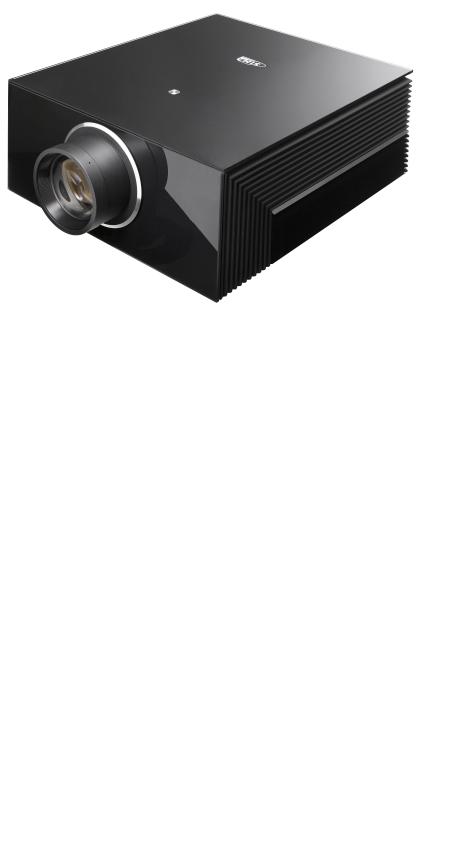
The M.150 is a high-end compact 3D single unit projector that incorporates PureLED technology, a combination of single chip DLP from Texas Instruments, three individual high power LEDs, a new light engine, and a dedicated video processing.
PureLED technology allows the projector to deliver clearer, brighter and more vibrant images, a wider and more consistent color gamut, and full-on/full-off contrast up to 100,000:1.
The M.150 is able to emulate the best 3D cinema projection systems, in terms of color fidelity, definition and depth of image. These are all conveyed accurately, as is the fluid motion of fast-action movies and sports. This all adds up to an incredible 3D experience at home.
The M.150 is designed for use with large screen sizes – up to 4 m (14 ft.) wide. A choice of two high quality glass lenses (T1 and T2) is available, giving the projectors a total throw ratio of 1.5-3.9:1.
To aid calibration SIM2’s Live Color Calibration software enables complete control over:
•primary, secondary and white point color coordinates
•gamma tables
allowing calibration experts to accurately calibrate the final image via a user-friendly application for Windows-based computers.
Key Features and Benefits
•high picture quality: SIM2 renown image processing and the latest 0.95 in. 1080p DMD from Texas Instruments
1 Introduction |
M.150 |
7 |
|
User Guide |
|
|
|
|

•precision optics: compact die-cast light engine with precision glass optics and motorized zoom, focus and lens shift
•longer light source life: typical life estimated around 30,000 hours
•richer and more saturated colors: wider and more consistent color gamut and full-on/full-off contrast up to 100,000:1
•extremely quiet level of operating noise: liquid-cooling system
•quick on/off: warm-up and cool-down periods require seconds not minutes
•artifact-free fast-action images: SIM2 PureMotion processing
•high resolution: actual full HD 3D images, without blur and ghosting
•comfortable 3D viewing: high brightness ghost-free sharp images
•immersive 3D effect: large screen sizes thanks to high brightness images
•3D wide viewing angle: stereo separation independent from viewing angles
•screen flexibility: no constraints in the choice of the screen material
•compatibility: no need of dedicated sources and preprocessing for 3D viewing
System Components
Your M.150 DLP projector ships with the following items:
•1 x backlit remote control unit (with four AAA/LR03 batteries)
•3 x AC power cords (US, EU and UK), 2 m (6.6 ft.) long
•3 x jacks for 12 V output connectors
•1 x User guide (this document)
•1 x CD with Live Color Calibration software (for Windows-based computers) If any items are missing or damaged, contact your SIM2 Authorized Dealer as soon as possible. Keep the original packaging in case anything has to be shipped.
Optional Accessories
•Visus system (4 SIM2 Visus active shutter glasses and 1 IR emitter for SIM2 Visus active shutter glasses)
•Projector ceiling bracket
•Anamorphic lens systems (fixed or motorized)
1 Introduction |
M.150 |
8 |
|
User Guide |
|
|
|
|

2 Overview
Projection Lens Available in two versions: T1 (1.5:1 to 2.1:1) and T2 (2.1:1 to 3.9:1)
Front IR Sensor Receives infrared signals from the remote control unit
Ventilation slots |
Ensure reliable operation and protect the projector from overheat- |
|
ing. Make sure they are not obstructed. |
Indicator light and Show projector status as follows:
status display |
Indicator light: |
|
|
• solid red = low power standby |
|
|
• |
solid orange = fast switch on standby |
|
• |
flashing green and red = initialization or cooling down |
•solid green = normal operation Status display:
•88 = initialization
•black = normal operation
•two-digit code = error status (displayed code may be useful for troubleshooting)
Rear IR Sensor Receives infrared signals from the remote control unit
|
Keypad |
Controls the main functions of the projector. Pull the cover to access |
|
|
the keys. See “Projector Keypad” on page 11 for a detailed |
|
|
description of their functions. |
AC receptacle and Plug here the female end of the AC power cord that is appropriate in main power switch your area. Switches the projector on or off.
Connector Panel Contains the connections for all input, control and output signals.
See “Connections” on page 12 for details
2 Overview |
M.150 |
9 |
|
User Guide |
|
|
|
|
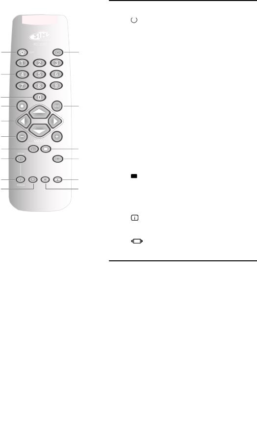
Remote Control
Custom Remotes
turn backlight on for about 5 seconds
|
|
|
|
turns the projector off |
|
|
|
||
|
|
|
||
|
1-9 |
select inputs and turn the projector |
||
|
|
|
|
on |
|
|
0 |
enters OSD Input menu and turns |
|
|
|
|
|
the projector on |
● OK enters submenus, confirms actions
|
|
ESC |
|
exits OSD |
|
|
|
|
select menu items, adjust settings or |
|
|
|
|
cycle through the test patterns |
|
|
|
|
|
MENU
+ / -
II
F1, F2
enter OSD Main menu and select the desired section, each press of the key selects the next tab in the menu
3D enters 3D menu
Memory enters Memories menu
perform user-defined actions (default assignments are: F1 = Zoom, F2 = Focus)
|
Info displays projector Info |
A Auto performs Auto Adjustment
|
Aspect enters Aspect Quick menu |
Not used
You can use your own IR remote control to control your M.150 projector.
•If you are using a remote control with learning capabilities, use the projector remote control to teach the commands to your remote.
•If you are using a programmable remote control, the setup software probably allows importing of Pronto Hex codes. See SIM2 M.150 IR Control for a list of all the projector codes in Pronto Hex format, including a number of discrete codes for:
◦Aspects
◦Memories
◦3D Controls (3D Mode and Input Formats)
2 Overview |
M.150 |
10 |
|
User Guide |
|
|
|
|
Operation
The M.150 projector has two IR receivers, one on the front and one on the back of the unit. The operative range of the remote control is approximately 10 m (33 ft.). Make sure that there is nothing obstructing the infrared beam between the remote control and the IR receiver you are pointing to. You can point the remote control towards the screen, as the IR beam is reflected by the screen towards front IR receiver of the projector. In this case the effective range of the remote control may be smaller than declared.
Note: In some cases when using 3D the accuracy and responsiveness of the remote control will be reduced.
Batteries
To install batteries in the remote control:
1.Open the battery cover.
2.Insert four AAA (LR03) batteries making sure the polarities match the + marks inside the battery compartment.
3.Replace the cover.
Replace the batteries with new ones when the operating range of the remote control decreases. Dispose of used batteries according to local regulations. Make sure you do not mix old and new batteries or different types of batteries.
Warning: If you will not use the remote control for a long time, remove the batteries to avoid battery leakage.
Projector Keypad
|
|
turns the projector on or off |
|
|
|
||
|
|||
select menu items, adjust settings or switch test patterns |
|||
MENU |
enters OSD Main menu and selects the desired section |
||
ESC |
exits OSD |
||
SOURCE/O |
enters OSD Input menu/selects a menu item |
||
|
|
|
|
|
|
|
|
2 Overview |
M.150 |
11 |
|
User Guide |
|
|
|
|
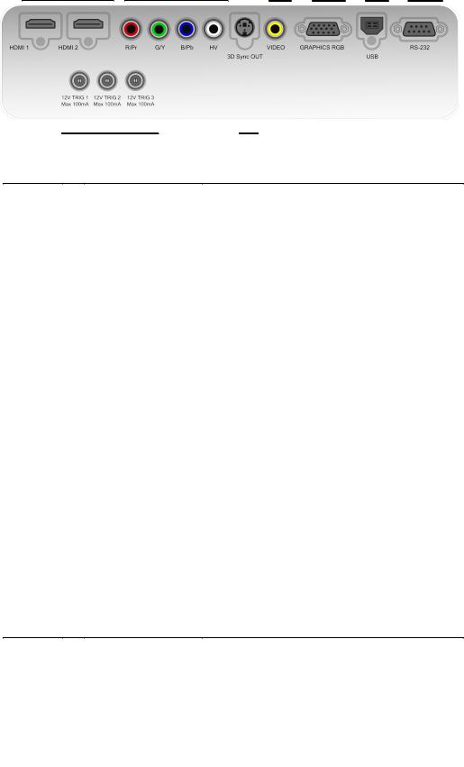
Connections
|
|
|
|
|
|
|
|
|
|
|
|
|
|
|
|
|
|
|
|
|
Inputs |
HDMI 1 |
Accept both HDMI and DVI digital video inputs. |
|
HDMI 2 |
|
|
Components/RGB-HV |
Four RCA connectors. They accept both standard |
|
|
and high-definition component (YPrPb) and |
|
|
RGB-HV signals. Also used as RGB input for SCART |
|
|
RGBS signals. |
|
Video |
One RCA connector. Accepts composite video sig- |
|
|
nals. Also used as composite sync input for SCART |
|
|
RGBS signals. |
|
Graphics RGB |
One D-Sub 15-pin female connector. Accepts |
|
|
component or RGB high-definition signals. |
|
|
|
Control/ |
USB |
USB 1.1 (type B) port for serial commands and |
Service |
|
firmware upgrade. |
|
RS-232 |
RS232 (female D-Sub 9-pin) port for serial |
|
|
commands and firmware upgrade. |
|
|
|
Outputs |
TRIG 1 |
12 V 100 mA max output, for motorized screen |
|
|
control. Activates when the projector is switched |
|
|
on. |
|
TRIG 2 |
12 V 100 mA max output, for motorized screen |
|
|
masking systems control. See “Screen” on page |
|
|
27. |
|
TRIG 3 |
12 V 100 mA max output, for motorized ana- |
|
|
morphic lens position control. See “Anamorphic |
|
|
Lens” on page 27. |
|
3D Sync OUT |
VESA DIN-3 connector for 3D IR Emitter cable. |
|
|
|
|
|
|
2 Overview |
M.150 |
12 |
|
User Guide |
|
|
|
|

3D IR Emitter
The 3D infrared emitter is designed to be placed near the projector and aimed at the screen. It receives the 3D sync signal from the projector and emits infrared pulses that bounce off the screen and the walls to reach the 3D glasses infrared receiver.
Note: The emitter emits sync pulses only when the projector displays 3D content.
3D Glasses
When displaying 3D content, the projector alternately displays one image for the left eye and one image for the right eye in rapid succession. The 3D glasses turn on and off their lenses, in sync with the projector, so that each eye receives exactly the image intended for it. The sync is possible thanks to the infrared pulses received by the glasses from the 3D IR emitter.
|
Battery compartment |
For CR2032 (3 V DC / 0.2 A) batteries |
|
Indicator light |
Indicates glasses status |
|
IR receiver |
Receives infrared signals from the 3D Emitter |
|
Lens |
Liquid crystal shutter |
|
Button |
Button for on and off |
|
|
|
|
|
|
2 Overview |
M.150 |
13 |
|
User Guide |
|
|
|
|

3 Installation
This section provides instructions for the installation of the M.150 projector. Important: Installation procedures should be performed by a qualified AV system specialist.
Location
When installing the M.150 projector, take the following considerations into account.
Installation Type
Select the installation type that best suits your needs:
•front or rear projection
•floor or ceiling mount
Lens Type
Choose the desired distance from the screen and select the lens type (T1 or T2) that determines the desired screen size.
Cooling
Make sure that the planned location for the projector has adequate ventilation. Check that room temperature is below 35° C and that the projector is away from heating vents. Ensure a minimum 0.25 m (10 in.) clearance on the left, right and rear sides of the projector.
Power Outlets
Verify that the powers outlets are grounded and preferably shielded from power surges and fluctuations. A UPS is optional. M.150 power supply operates on any nominal line voltage between 100-240 V AC, 50-60 Hz.
Cables
Check planned cable lengths for video and control cables and make sure these lengths do not exceed specifications.
Ambient Light
Avoid or minimize light sources directed at the screen to preserve the quality of the projected image.
Mounting
The projector can be Floor mounted (upright) or Ceiling mounted (inverted). Choose the method that best suits your installation.
Important: The projection lens is centered to the chassis, see “Dimensions” on page 40 for details). Make sure the centerline of the lens is centered horizontally to the center of the screen.
Floor Mounting
Position the projector on a secure and flat surface (such as a table or a shelf). Adjust the four feet at the bottom of the projector until the projector is level on all sides.
3 Installation |
M.150 |
14 |
|
User Guide |
|
|
|
|
Loading...