

Page 1

Operation manual
KH 2380
Page 2

GB / IE Operation and Safety Notes ...................................... Page 5
Page 3
A
co
cp
123 4
cn
cm
cl
bu
bt
B
789blbmbnbobpbqbrbs
5
6
cr
cq
C
cs
ds
cuct dl dm
dn
do
drdp dq
dp
Page 4
D
go
duelen ep
er
gngm dt
E
es
eq
gp
fo
fqfrfugl fsft
et
eofm
F
gqgr hngtgu
fpfnem
eufl
in hm
il
hu
iq
ht hr
G
gs
hlip
hoio
hqim
hp
hs
irisit
Page 5

Introduction
For your personal safety ........................................................................... Page 6
Proper Use ............................................................................................... P
Equipment ................................................................................................ Page 6
Scope of Supply ....................................................................................... P
Technical Information ............................................................................... Page 8
A
udio Storage Media ................................................................................ Page 8
age 6
age 7
Safety
Important specific notes on safety ........................................................... Page 9
Preparation ............................................................................................ Page 11
Installation
Removing the control panel from the car radio ......................................... Page 11
Installation of the DIN assembly bracket into the car’s instrument panel .. P
Connection to the car’s loudspeaker ........................................................ Page 12
Connection with car’s 12 V DC power supply ............................................ Page 12
C
onnection with CD Changer ................................................................... Page 13
C
onnection of an amplifier ....................................................................... Page 13
Connecting a portable audio device ......................................................... Page 13
Connecting to the aerial of the motor vehicle ........................................... Page 14
Attaching to the DIN assembly bracket .................................................... Page 14
Attaching the control panel ...................................................................... P
age 11
age 14
Content
Operation
Switching on ............................................................................................ Page 14
Turning off ............................................................................................... Page 15
Selecting and adjusting the sound ............................................................ Page 15
Selecting and adjusting playback functions .............................................. P
Adjusting volume ...................................................................................... P
Setting the 3-Band PLL Tuner .................................................................. Page 16
P
laying from audio storage media ............................................................ Page 18
CD, CD-R and CD-RW ....................................................................... Page 18
USB Memory Stick, MP3 Player or SD / MMC .................................... Page 20
Recording /
Storing / Deleting on SD, MMC or a USB Memory Stick ........... Page 21
age 15
age 16
Promote Control .................................................................................. Page 22
Troubleshooting .................................................................................. Page 23
Maintenance and Service .............................................................. Page 23
Disposal ................................................................................................... Page 24
Information
Important warranty notes ......................................................................... Page 24
Importer ................................................................................................... P
age 24
5 GB/IE
Page 6

Introduction
Car Radio KH 2380
L Introduction
L For your personal safety
Please read the operating instructions carefully; to
do so, unfold the pages featuring the illustrations.
Pay precise attention to the notes when taking the
device into operation. Should you have any further
questions on how to use this car radio recorder,
please contact your national service point (see
guarantee card). Store the operating instructions
safely for later reference and hand them to third
parties when passing your car radio recorder to a
new user.
L
Proper Use
The KH 2380 car radio is suitable for private use for
receiving radio stations in the FM / MW / LW range and
for playing back CD, CD-R, CD-RW, USB MemoryStick, MP3 Player, SD and MMC audio storage media.
It is able to make recordings in WMA format on to
SD, MMC or USB memory stick (not supplied) of the
radio stations being played back. The car radio has
a removable control panel and an IR remote control
device which can only be supplied with electricity by
means of 1 lithium ba
The car radio may only be connected to the 12 V
DC supply. The device is suitable for connecting to
four loudspeakers with an impedance of 4-8 Ohm,
a maximum of four power amplifiers (to the four
speaker output channels) and a CD changer.
Any careless use or use other than for the intended
purpose will result in the guarantee becoming invalid.
ttery of type CR2025, 3 V DC.
L
Equipment
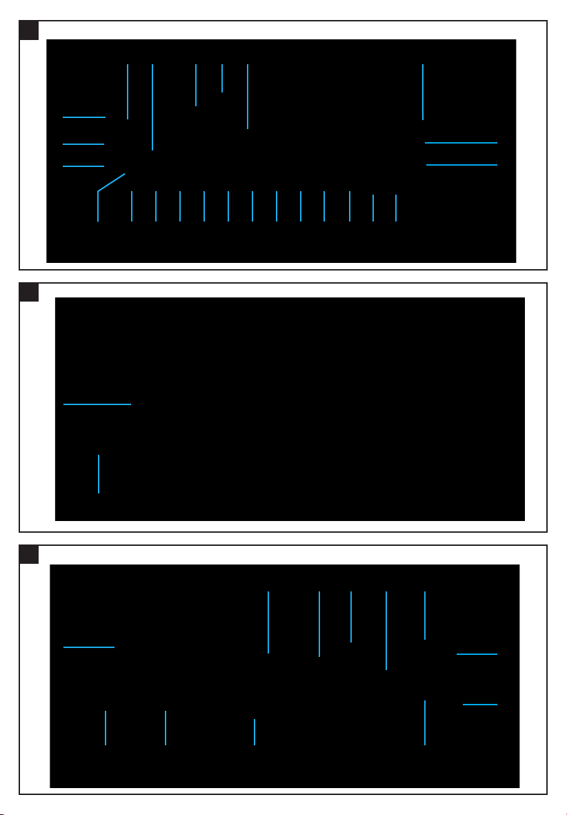
Front of the Control Panel (Fig. A)
1 Control panel
2 Plastic frame
3 Display window
4 “Open” button
:
5
6
7
8
9
bl
bm
bn
bo
bp
bq
br
bs
bt
bu
cl
cm
cn
“Skip” button (forwards)
9
“Skip” button (reverse)
PTY
4 RDM
3 INT
2 RPT
1 PAU
DISP
BD / ENT
SCAN
•
A / PS
PWR / DIM
AF
TA
6
5
LD / MD
MU
“AF” button
“TA” button
“PTY” button
“6” button
“5” button
“4 / RDM” button
“3 / INT” button
“2 / RPT” button
“1 / PAU” button
“DISP” button
“BD/ENT” button
REC•
“SCAN / REC” button
“LD / MD” button
“MU” button
“A / PS” button
“PWR / DIM” button
co Sensor (remote control)
cp “SEL / VOL” control knob
Reverse of the Control Panel (see Fig. B)
cq Unlock mechanism 2 x
cr Plug-in connection strip
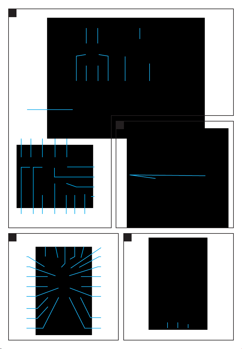
Front of the Car Radio
(Control Panel removed) (see Fig. C)
cs LED (red) / CD compartment
ct Front
cu CD compartment
dl Connection socket
dm Opening mechanism
dn SD and MMC port
do USB port
dp Control panel attachment point 2 x
dq LED (red) / power supply
dr Reset button
ds CD eject button
6 GB/IE
Page 7
Reverse of the Car Radio (see Fig. D)
dt Metal housing with vents
du ISO plug jack for loudspeaker connection
el Plug-in for rear right loudspeaker (+)
em Plug-in for rear right loudspeaker (-)
en Plug-In for front right loudspeaker (+)
eo Plug-in for front right loudspeaker (-)
ep Plug-in for front left loudspeaker (+)
eq Plug-in for front left loudspeaker (-)
er Plug-in for rear left loudspeaker (+)
es Plug-in for rear left loudspeaker (-)
et Flat blade fuse socket
eu Flat blade fuse 10 A
f l ISO plug jack to the 12 V DC power connection
(including connection of an automatic aerial)
fm Plug-in for 12 V DC constant current
fn Plug-in for electric aerial
fo Plug-in for 12 V DC ignition current
fp Plug-in for minus / earth connection in the vehicle
fq DIN 8-pole plug jack (CD changer connection)
fr Attachment screw
(including M5 nut and washer)
fs LINE IN R cinch plug jack (red / right)
ft LINE IN L cinch plug jack (white / left)
fu OUT / REAR cinch R plug jack
(loudspeaker connection [red / rear right])
gl OUT / REAR cinch L plug jack
(loudspeaker connection [white / rear left])
gm OUT / FRONT cinch plug jack
(loudspeaker connection [red / front right])
gn OUT / FRONT cinch plug jack
(loudspeaker connection [white / front left])
go Aerial socket
Top of the Car Radio (see Fig. E)
gp Transport safety screw 2 x
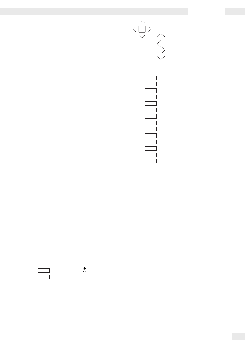
Front of the Remote Control (see Fig. F)
DIM
POWER
SEL
“DIM POWER /
“SEL” button
“ button
gq
gr
Introduction
VOL+
gs “TUNE / SEEK” multifunction button:
TUNE /
:
9
SEEK
gu
hl
hm
hn
ho
hp
hq
hr
hs
ht
hu
il
im
in
io
ip
iq
Rear of the Remote Control (see Fig. G)
LOUD
MP3
D-DN
D-UP
SCAN
RDM
INT
RPT
PAU
ENTER
VOL -
VOL+
gt
MODE
AS /
TA / TP
DISP
BAND
MUTE
“VOL+” button (upper)
9
Skip button (reverse)
:
Skip button (forwards)
VOL-
“VOL” button (lower)
“MODE / LOUD” button
PS
“MP3 / AS / PS” button
5
“D-DN / 5” button
6
“D-UP / 6” button
PTY
“PTY” button
“TA / TP” button
“DISP” button
REC
“REC / SCN” button
4
“4 / RDM” button
3
“3 / INT” button
2
“2 / RPT” button
1
“1 / PAU button
“BAND / ENTER” button
“MUTE” button
ir Battery compartment
is Battery holder
it Unlock button
Scope of Supply
L
1 x Car radio (including control panel)
1 x IR remote control (including 1 x lithium battery
of type CR2025, 3 V DC)
1 x Plastic box (for control panel)
1 x DIN assembly bracket
2 x Installation key
1 x Anchoring plate (including attachment material)
1 x Set of instructions
7 GB/IE
Page 8

Introduction
L Technical Information
Car Radio
Nominal volta
connected to vehicle’s chassis)
P
ower consumption: max. 10 A
Output: max. 4 x 20 W active power factor
Distortion: - 40 dB (1%)
Amplifier TAD 7386
4 band preset EQ
Electronic master level for: Low-frequency and
high-frequenc
balance
Pre-amplifier In (LINE IN )
Input level:
Impedance: 47 k Ohm
Pre-amplifier Out (LINE OUT)
Output:
Impedance: 4,7 k Ohm
Sound control
Bass frequenc
High frequency: 10 kHz ± 10 dB
ge: 13.8 V DC (minus pole negative,
y sound, loudness, fade-in / fade-out,
775 mV = 0 dB
2000 mV
y: 100 Hz ± 10 dB
FM band (FM 1, FM 2, FM 3)
F
requency band: 87.5 - 108 MHz
Channel increment: 50 kHz
Intermediate frequency: 10.7 MHz
Stereo separation: 25 dB
Noise cancellation: 50 dB
Pre-set stations: 18
MW Band (MW 1, MW 2)
F
requency band: 530 - 1600 KHz
Interim frequency: 450 KHz
Available sensitivity: 32 dB µV
Pre-set stations: 12
LW Band (LW 1)
F
requency band: 144 - 290 KHz
Interim frequency: 450 KHz
Available sensitivity: 32 dB µV
Pre-set stations: 6
IR remote control
Nominal volta
Power supply: 1 x Lithium battery type CR2025, 3 V DC
Current consumption: approx. 30 mA
Wave range: near-infrared 0.7 - 1.4 µm
Dimensions: 85 x 6 x 52 mm (L x H x W)
ge: 3 V DC
Connections
12 V DC
ISO:
ISO: loudspeaker (max. 2 pairs) (4 - 8 Ohm)
MP3 player or USB memory stick
(USB 1.1 and 2.0)
SD or MMC
CD changer
Max. four amplifiers
Display
Liquid crystal screen
(8-digit alpha-numerical Dot Matrix LCD Display)
Background lighting
(colour blue, 2 dimming levels)
3 Band PLL Tuner
Display: frequency band, radio stations, mono or
s
tereo reception, pre-sets, activated EON, AF, TA / TP
and mute function
8 GB/IE
Audio Storage Media
L
Play
Data formats: MP3 with ID3, WMA compatible
Media: CD, CD-R, CD-RW, SD, MMC, USB 1.1 and
2.0 (stick or plug-in connection)
Noise cancella
Channel separation: > 50 dB
Frequency range: 20 Hz - 20 kHz
Display: Directory, file, track, album, artist, duration
Search function: File, track and starting letter are
displayed
Recording
Data formats: WMA
Storage devices: SD, MMC or USB memory stick
Playback source: 3-band PLL tuner
Display: Directory, file, track, album, artist, duration
tion: > 60 dB
Page 9

Safety
L Safety
Important specific notes on safety
The following notes are for your safety and satisfaction
in operating the device. Please observe that noncompliance with these safety notes may lead to
substantial risks caused by accident.
Explanation of the icons and terminology used.
c D
anger! Avoid risk to life!
m Caution! Avoid risk of injury and damage to
property!
Tip! What to do!
c Danger!
·
Do not allow small children unsupervised near
the packaging material! Risk of suffocation!
·
Do not allow infants and children unsupervised
into the vicinity of the device!
·
Protect yourself against an electric shock!
Avoid any short circuits during connections:
-
with the vehicle’s 12 V DC power supply
- with the max. 2 pairs of loudspeakers with
the impedance 4 - 8 Ohm
- with a CD changer
- with a terminal amplifier
· Before connecting to the 12 V DC power supply
of a car, obtain information on how to maintain
electrical safety based on the vehicle‘s
operation manual!
· Ensure that when connecting to a vehicle‘s
12 V DC power supply, there is no voltage in the
vehicle‘s connecting cables. Equip the
onnecting cords with fuse holders (3 x 15 A)!
c
· When installing into a car, ensure that the vehicle
is out of operation and in a secure standstill
position! Turn off the ignition and bring the vehicle
into parking position with applied hand-brake.
·
Complete the connection to the 12 V DC power
supply while fully protected against humidity!
·
Complete the installation in a car, the assembly,
the maintenance and the service disconnected
from the 12
· Do not expose the device to moisture, fire, heat
V DC power supply!
and sustained temperature in excess of 50° C!
· Do not damage any lines carrying fuel or for
electricity, brakes, hydraulics, water or data
transfer when tightening the screws!
Ensure that the 12 V DC constant current plug-
·
in
fm, the 12 V DC ignition current plug-in
foand possibly the powered aerial plug-in fn
do not come into contact with a fuel line (e.g.
petrol-carrying line)!
·
Do not allow yourself to be distracted while
driving by operating the car radio or from its
displays! Familiarise yourself with its operation
before driving and practise the safe use of the
car radio’s features! Set the volume only to such
level that the sirens of emergency vehicles can
be heard on time.
m Caution!
·
Avoid injuries and damage to the sensitive sense
of hearing of passengers (in particular infants,
children and pets) while in the car! Adjust the
volume and balance of the loudspeakers for all
passengers to a healthy and comfortable level!
·
Adjust the volume such that you can always
hear the warning signals of other road users.
·
Before operation, check if all components have
been assembled in accordance with the operating
instructions!
·
Before assembly and operation, check the delivery
for damage and completeness!
·
Use the car radio only with the supplied
original parts!
·
Do not cover the metal casing
· Protect all electronic contact areas against
short circuiting, humidity, damage and impurities!
·
Do not place the device on or near a car battery!
· Prevent a short circuit and damage! Ensure that
no alien matter or objects can access the inside!
Disconnect the car radio in the event of
·
operational malfunctioning and damage
instantly from the 12
· Connection to the loudspeakers, CD changer,
amplifier and audio storage devices (CD, CD-R,
CD-RW, USB memory stick, MP3 player, SD,
and MMC) must be carried out as described in
the relevant operating manual.
·
Have the car radio repaired exclusively by
V DC power supply!
dtwith objects!
9 GB/IE
Page 10

Safety
authorised and trained professional staff! In the
event of repairs, contact your national service
point (see guarantee card)!
·
Do not expose the device to mechanical stress!
· Avoid theft and unauthorised use especially if
the device has been installed in a car! Before
leaving the parked vehicle, remove the control
panel of the car radio and store it safely in the
plastic box.
·
Exchange any defect fuses only against new
fuses of the same type with identical A (Ampere)
rating!
·
If not used for extended periods of time, remove
the battery from the remote control!
Tip! What to do!
· When recording radio programmes please
observe the copyright regulations of the
country in which you are using the device.
·
Prepare yourself and take your time when
familiarising yourself with the car radio’s
operation! Ensure a tidy environment in which
you are not disturbed and perform the initial
operation with maximum concentration.
·
Carefully plan the assembly point. Observe that
the assembled car radio does not cause
obstruction while driving the vehicle.
·
The audio data of a CD-R, CD-RW can only be
played if they were fully burnt on to the media.
·
Use the highly sensitive CD-R, CD-RW in
accordance with their operating instructions!
·
Avoid interruptions while playing audio storage
media! Clean the CD, CD-R and CD-RW before
use with a dry anti-static cloth, wiping from the
centre toward the edge of the disk!
·
Ensure that the playing of audio storage media
is not interrupted by condensation! Remove the
CD, CD-R, CD-RW in the case of high humidity
and low ambience temperatures from the device.
·
Please ensure that audio storage media used
for playback are not exposed to condensation!
Remove CDs, CD-Rs and CD-RWs from the
device if the humidity is high and the ambient
temperatures low.
Use audio storage media only with completely
dry surfaces.
·
Store audio storage media outside of the device
in an appropriate protective cover.
Obtain an overview of the most important specific
·
terminology:
i
Receiver: Electronic receiver for radio
broadcastings and sound data of storage
media and simultaneously pre-amplifier.
i
Tuner: Receives and issues radio signals.
i
P
LL (Phase-locked-loop): Electronic
switching which enables precision reception of
radio frequencies.
i
FM (Ultra-short wave): Band receiver for
radio broadcasting (Frequency range:
8
7.5 - 108 MHz).
i
MW (Medium wave): Band receiver for radio
b
roadcasting (Frequency range: 530 - 1600 KHz).
i
L
W (Long wave): Band receiver for radio
broadcasting (Frequency range: 144 - 290 KHz).
i
CD /
CD-R / CD-RW (Compact Disc): Storage
medium for sound and image data (disk ø
a
pprox. 120 mm).
i
U
SB (Universal Serial Bus): Universal
interface for data transmission.
i
SD (Secure Digital Card): Storage media for
sound and image data (rectangular approx.
24
x 1 x 32 mm).
i
MMC (Multimedia Card): Storage media for
sound and image data (rectangular approx.
24
x 1 x 32 mm).
i
MP3 (Moving Picture Experts Group Layer 3):
Compressed audio format.
i
I
D3: Additional information which provides details
on track and artist of audio files (e.g. MP3).
i
WMA (Windows Media Audio):
Compressed audio format.
i
LINE IN: Connection for feeding audio data
into a HiFi device.
i
L
INE OUT: Connection to send out audio data
from a HiFi device.
i
Cinch: Standardised plug connector to transfer
electrical signals.
i
RDS (Radio Data System): Encrypted
additional information broadcast by radio
stations in addition to conventional music and
language.
i
AF (Alternative frequency): Function to
automatically receive the optimum frequency
of the programme tuned into.
10 GB/IE
Page 11

i
T
A / TP (Traffic Announcement/Traffic
Program): Function to receive traffic updates.
i
EON (Enhanced Other Networks): I
function is activated, while listening to a
broadcasting of a radio station the programme
switches automatically as soon as traffic updates
are broadcast. Traffic updates are then
broadcast at a pre-set volume.
i
PTY (Program Type): Function to receive
special program (e.g. rock music).
i
HiFi (High Fidelity): Quality standard for audio
replay devices.
i
D
IN 8 pole plug : adapter to connect electronic
HiFi device in accordance with DIN standard (e.
g. CD changer connection to a MP3 car radio
recorder).
i
I
SO plug: Adapter to connect electronic HiFi
devices
in accordance with International
Organization for Standardization.
f TA / TP
Safety / Preparation / Installation
To connect a final amplifier you require :
x Cinch connecting cable
2
(insula
tion and plug: white / red)
For the connection of a portable audio device
you require:
x Cinch connection cable / 3.5 mm jack
1
(insulation and plug: white / red)
To record MP3 or WMA formats you require:
x MMC approx. 1 GB storage capacity
1
or
1
x SD approx. 1 GB storage capacity
or
1
x USB memory stick approx. 1 GB storage
capacity
L Installation
L Preparation
The following auxiliaries and tools are required for
the connection and for the assembly, which are not
included in the delivery:
1
x ISO plug to connect car’s loudspeaker
1 x ISO plug to make 12 V DC connection
x Powered aerial connection with connector
1
1 x Pair of loudspeakers impedance 4 - 8 Ohm,
(incl. feed line)
3
x Fuse holder with fuse 15 A
1 x DIN assembly cut-out in car’s instrument panel
9 x Biscuit connectors
1 x Stripping tongs or cable stripping knife
1 x Screw driver
1 x Spanner with 8 mm opening
1 x Biro
To connect an antenna already installed in the
vehicle you may need:
1
x Antenna adapter (in accordance with the
Technical Data for the antenna)
To connect a CD changer you require:
1
x Connecting line with DIN-8-pole plug
L Removing the control panel
from the car radio
• Avoid hard contact with the display window 3.
• Press the “Open” button
control panel
position.
•
Push the control panel
pull it forwards.
•
Store the control panel in the plastic box (see
also the illustration in the section “Attaching
the Control Panel”).
L
Installation of the DIN assembly
1to reach the horizontal
4and allow the
1slightly to the left and
bracket into the car’s instrument
panel
• Completely unscrew the safety transport
screws
gpfrom the metal casing dt(see Fig. E)
and carefully remove the plastic frame
from the front of the device ct.
• Release the attachment points by slightly
raising the upper frame edge and pulling it
carefully towards the front.
•
Push the two installation keys between the
2
11 GB/IE
Page 12

Installation
metal housing dtand the preassembled DIN
assembly bracket until they clearly lock in place.
Ensure that the convex side faces outwards in
each case. Store the installation keys carefully
for future use.
•
Remove the DIN assembly bracket and place it
flush in the DIN assembly cut-out of the
vehicle’s instrument panel.
•
Secure the DIN assembly bracket against removal.
Bend approximately ten tin dog points on both
the upper and lower side of the DIN assembly
bracket from the inside towards the outside.
Please ensure that the DIN assembly bracket is
installed flush in the DIN assembly cut-out.
•
Attach the plastic frame
front of the device
Connection to the car’s loudspeaker
L
Tip! Use an ISO plug.
• Lead the connecting cables for the speakers
already installed in the vehicle carefully out of
the DIN mounting frame at the front.
•
Hook up the connecting cable of the ISO plug
with the connecting cable of the loudspeakers
fitted in the car with the help of eight biscuit
connectors. Ensure that the connection of the
eight biscuit connectors does not cause any
short circuits and that the fixing screws are
firmly tightened.
•
Hook up the connecting lead of the plug in
with the (+) lead for the rear right loudspeaker.
•
Hook up the connecting lead of the plug in
with the (–) lead for the rear right loudspeaker.
•
Hook up the connecting lead of the plug in
with the (+) lead for the front right loudspeaker.
•
Hook up the connecting lead of the plug in
with the (–) lead for the front right loudspeaker.
•
Hook up the connecting lead of the plug in
with the (+) lead for the front left loudspeaker.
•
Hook up the connecting lead of the plug in
with the (–) lead for the front left loudspeaker.
•
Hook up the connecting lead of the plug in
with the (+) lead for the rear left loudspeaker.
•
Hook up the connecting lead of the plug in
with the (–) lead for the rear left loudspeaker.
2completely to the
ct.
Connection with car’s 12 V DC
L
power supply
c Danger!
· Before hooking up to the car’s 12 V DC power
supply consult the vehicle’s operation manual on
how to observe electrical safety!
·
Ensure that when connecting the 12 V DC power
supply there is no voltage on the vehicle’s
connecting cords. Do not damage any safety
facilities, e.g. board computer and alarm system
of vehicle.
·
Connect the 12 V DC power supply with the 3 x
15 A fuse holders!
· During vehicle installation ensure that the vehicle
is out of operation and is in safe standstill! Turn
off the ignition and bring the vehicle into parking
position with activated hand-brake!
·
During connection, use tools with double-
insulated handle!
·
Avoid electrical short circuits when connecting
to the 12 V DC power supply.
· Connect the car radio with the 12 V DC power
supply while fully protected against humidity!
Tip! Use an ISO plug.
• Ensure that the fault-free flat blade fuse 10 A
is inserted all the way to the catch of the flat
blade fuse socket
• Carefully guide the connecting cable to hook up
el
em
en
eo
ep
eq
er
es
the 12 V DC power supply through the front out
of the DIN assembly bracket.
Connect the ISO plug with the connecting cables
•
of the 12 V DC power supply with the 3 x 15 A
fuse holders. Ensure that the connections of
x 15 A fuse holders do not cause any
the 3
short circuits and that the fixing screws are
firmly tightened.
•
Connect the cable for the 12 V DC constant
current plug-in
with the vehicle’s connecting cable for the
12
V DC constant current.
• Optional - only if an electric aerial is connected:
Using one 15 A fuse holder each, connect the
cables for the 12 V DC ignition current
electric aerial
et.
fmusing a 15 A safety holder
fnplug-ins to the connection
eu
foand
12 GB/IE
Page 13

Installation
cable for 12 V DC ignition current of the vehicle.
In this manner the car radio and an electric
aerial can only use current from the vehicle
when the ignition is switched on.
•
Connect the cable for the vehicle’s minus/
ground connection plug-in
a biscuit connector with the car’s connection
cable for the minus pole (battery’s minus pole
which by standard is connected with the car’s
chassis).
L
Connection with CD Changer
Tip! Use a connecting cable with DIN 8-pole plug.
A standard CD changer with DIN 8-pole connector
can be connected to the device.
•
Install the connecting cable with the DIN 8-pole
plug in accordance with its operation manual
in the car.
Guide the connecting cable with the DIN 8-pole
•
plug to the CD changer and carefully out of the
front of the DIN assembly bracket.
•
Insert the DIN 8-pole plug of the connecting cable
until it catches into the DIN 8-pole plug jack
AUX
fqto the rear of the casing.
• Insert the DIN 8-pole plug to the other end of the
connecting cable until it catches into the DIN
8-pole plug-jack AUX of the CD changer.
fpwith the help of
cable as far as it will go into the OUT / REAR
cinch R plug jack (amplifier connection
[red
/ rear right])
• Then insert the two red plugs of the first cinch
connection cable as far as it will go into the
REAR cinch R plug jack (amplifier connection
[red
/ rear right]) of the amplifier.
• Insert the white plug of the first cinch
connection cable as far as it will go into the
/ REAR cinch L plug jack (amplifier
OUT
connection [white / rear left])
• Then insert the second white plug of the first
cinch connection cable as far as it will go into
the REAR cinch L plug jack (amplifier
connection [white
• I nsert the red plug of the second cinch
connection cable as far as it will go into the
/ FRONT cinch plug jack (amplifier
OUT
connection [red / front right])
• Then insert the second red plug of the second
cinch connection cable as far as it will go into
the FRONT cinch plug jack (amplifier
connection [red
• Insert the white plug of the second cinch
connection cable as far as it will go into the
/ FRONT cinch plug jack (amplifier
OUT
connection [white / front left])
• Then insert the second white plug of the
second cinch connection cable as far as it will
go into the FRONT cinch plug jack (amplifier
connection [white
fu.
gl.
/ rear left]) of the amplifier.
gm.
/ front right]) of the amplifier.
gn.
/ front left]) of the amplifier.
L
Connection of an amplifier
Tip!
Use two cinch connection cables
(insula
tion and plug: white / red).
One amplifier per speaker output channel can be
connected to the device.
•
Install the two cinch connection cables in the
vehicle according to their operating instructions.
Pass two cinch connection cables to the
•
amplifier and carefully out of the front of the DIN
assembly bracket.
•
Insert the red plug of the first cinch connection
Connecting a portable audio device
L
For establishing a cinch connection to any audio
source the headphone output (3.5 mm stereo jack)
of any audio device (e.g. MP3 player) can be
connected to the car radio.
Use a 3.
5 mm jack plug connection cable to 2x
cinch plugs.
•
Guide the cinch connection cable to the portable
audio device and carefully out of the front of
the DIN assembly bracket.
Insert the red plug of the cinch connection
•
cable as far as it will go into the LINE IN R
13 GB/IE
Page 14

Installation / Operation
cinch plug jack [red / rear right] fs.
• Insert the white plug of the cinch connection
cable as far as it will go into the LINE IN L cinch
plug jack [white
• Then insert the 3.5 mm stereo jack into the
headphone output of the audio device.
•
In order to play back the sound, press the
•
LD / MD
appear in the display window.
•
For operation of the external device, please see
its operating instructions.
L
Connecting to the aerial
/ rear left]
button buuntil the letters AUX
ft.
of the motor vehicle
• Guide the connection cable of the vehicle aerial
carefully out of the front of the DIN assembly
bracket up to the car radio.
•
Insert the plug of the connection cable of the
vehicle aerial as far as it will go into the aerial
socket
goof the car radio.
If necessary, use an aerial adapter in accordance
with the technical data of the aerial.
•
If present: Connect the 12 V DC connection cable
of an electric aerial to the electric aerial
plug-in.
fn
anchoring plate and the attachment material to
the engine fire wall of the vehicle.
• Ensure that all cables are properly connected
and that the power supply is working correctly.
The LED (red)
• Use the tip of a ballpoint pen to press the reset
button
Attaching the control panel
L
• Remove the control panel 1from the plastic
box.
•
Avoid hard contact with the display window
• Place the rear left-hand edge of the control
panel
/ power supply
dqflashes.
dron the front of the device (see Fig. C).
3.
1on the control panel attachment point
dpon the front of the device.
• Ensure that the plug-in connection strip
positioned in front of the connection socket
• Carefully press the rear right-hand edge of the
control panel
attachment point
place.
•
Fold the control panel
to lock into place.
1against the control panel
dpuntil it distinctly locks into
1upwards and allow it
cris
dl.
Attaching to the DIN assembly
L
bracket
• Insert the rear of the car radio together with
the connected cables carefully into the DIN
assembly bracket.
•
Ensure that no objects are able to cover the
vents of the metal housing
• Ensure that there is no connection cable
between the metal housing
assembly bracket. Prevent the cables from
becoming caught, as any damage may result in
a short circuit and malfunctioning of the device
or the vehicle’s electronic system.
•
Push the car radio into the DIN assembly bracket
until it distinctly locks into place.
•
You should also secure your device against
theft. Fix the attachment screw
14 GB/IE
dt.
dt and the DIN
frwith the
L Operation
L Switching on
• Press the
The factory settings of the device are as follows:
•
The word [WELCOME] appears in the display
window
• The buttons are illuminated in blue (these can
be adjusted on two levels).
PWR / DIM
3.
button cn.
Page 15

Operation
• Press the
brightness (dimming).
-
The tuner is activated and [ FM 1] (1st FM
- The loudspeakers play back the reception from
•
Turn the “SEL / VOL” control knob
the volume as desired.
Turning off
L
• Press and hold the
seconds. The background light of the control
panel
reads [GOODBYE]. When turning off, the
device stores all settings from the last
operation. When turning the device on again,
the last used audio storage medium or the
tuner starts to play.
L
Selecting and adjusting the sound
VOL: Volume of the loudspeakers
• Adjust the loudspeakers to the desired volume
by turning the “SEL / VOL” control knob
BAS: Bass (lower range of the loudspeaker sound)
•
Press THE “SEL / VOL” control knob
[BAS] appears in the display window
• Turn the “SEL / VOL” control knob
desired bass level.
V
alues between [-7] and [7] can be selected.
TRE: Treble (higher range of the loudspeaker sound)
•
Press the “SEL / VOL” control knob
repeatedly until [TRE ] appears in the display
window
• Turn the “SEL / VOL” control knob
desired treble level.
V
alues between [-7] and [7] can be selected.
BAL: Balance (difference in volume between the
left and right loudspeakers)
• Press the “SEL / VOL” control knob
PWR / DIM
button cn and adjust the
band),
87.50 (station frequency) appears in
the display window
the tuner.
3. [EON] and [AF] flash.
cpto adjust
PWR / DIM
button cn for two
1goes out and the display window 3
cp until
cp to set the
cp
3.
cp to set the
cp until
cp.
3.
[BAL] appears in the display window
• Turn the “SEL / VOL” control knob
desired balance.
Values between [8L] and [8R] can be selected.
The mean value is [0].
FAD: Fading (difference in volume between the
front and rear loudspeakers)
•
Press the “SEL / VOL” control knob
[FAD] appears in the display window
• Turn the “SEL / VOL” control knob
desired fading level. Values between [8F] and
[8R] can be selected. The mean value is [0].
Your settings are automatically stored.
L
Selecting and adjusting
3.
cp to set the
cp until
3.
cp to set the
playback functions
• Press the “SEL / VOL” control knob cp and keep
it held down for two seconds.
In order to select the next function press the
“SEL
/ VOL” control knob
reached the required function.
INVOL: Volume when switching on.
•
Turn the “SEL / VOL” control knob
desired volume of the car radio when
switching on.
ADJ: Time display.
•
Set the desired hour setting by turning the
“SEL / VOL” control knob
• Set the desired minute setting by turning the
“SEL / VOL” control knob
TAVOL:
Volume at which the traffic information is
played back from the tuner.
• Turn the “SEL / VOL” control knob
desired volume of the traffic information
played through the tuner. Please ensure that
this important information for road users is
loud enough for you to hear.
Note: If the volume is too high there is a danger
that you will be startled or unable to hear other
road users.
cp until you have
cp to set the
cp clockwise.
cp counter clockwise.
cp to set the
15 GB/IE
Page 16

Operation
EON: (ON / OFF): EON function on or off.
• Turn the “SEL / VOL” control knob
display
3reads [EON ON]; the EON function
is now activated.
•
Turn the “SEL / VOL” control knob
display
3reads [EON OFF]; the EON function is
now deactivated.
DSP: (NONE
Selection of an acoustic pattern for various
•
Turn the “SEL / VOL” control knob
•
Turn the “SEL / VOL” control knob
•
Turn the “SEL / VOL” control knob
•
Turn the “SEL / VOL” control knob
•
Turn the “SEL / VOL” control knob
Your settings are automatically stored.
The device automatically changes back to playback
mode after five seconds.
L
Adjusting volume
• Increase the volume by turning the “SEL / VOL”
• Reduce the volume by turning the “SEL / VOL”
Mute Function
The mute function enables you to turn off the
loudspeakers.
•
Press the
• Press the
/ CLAS / ROCK / POP / FLAT):
playback styles of music and language with
preset bass and treble levels.
[NONE] appears in the display window
acoustic pattern of your setting for [BAS] and
[TRE] is selected.
[CLAS] appears in the display window
acoustic pattern for classical music is selected.
[ROCK ] appears in the display window
acoustic pattern for rock music is selected.
[POP] appears in the display window
acoustic pattern for pop music is selected.
[FLAT] appears in the display window
acoustic pattern for speech is selected.
control knob
control knob
and [MUTE] appears in the display window
cpclockwise.
cpcounter clockwise.
MU
button cl. Playback is muted
MU
button cl again. Playback
cp until the
cp until the
cp until
3. The
cp until
3; the
cp until
3; the
cp until
3; the
cp until
3; the
3.
continues as before the MUTE function was
activated and [MUTE] disappears from the
display window
Loudness Function
The loudness function increases the playback level
of the bass sounds when the volume is low.
•
Press the
down for approximately 2 seconds. The loudness
function is activated, [LOUD ON] appears in
the display window
• Turn the “SEL / VOL” control knob
[LOUD OFF] appears in the display window.
•
Press the
it held down for approximately 2 seconds. The
loudness function is deactivated, [LOUD OFF]
appears in the display window
[LOUD].
Setting the 3-Band PLL Tuner
L
Press the
in the display window
You can select 3 x FM frequency bands (FM1, FM2
and FM3), 2 x medium wave frequency bands (MW1
and MW2) and 1 x long wave frequency band. Each
frequency band has six presets on which you can
store radio stations.
•
Press the
Automatic Station Search
•
Start the station search at lower frequencies
• Start the station search at higher frequencies
•
frequency band you wish to receive. In the display
window
the frequency band (e.g. [FM2]), the frequency
(e.g. [99.20]) of a radio station that is being
received or the programme ID during stereo
reception and [TP] for traffic information.
by briefly pressing the
tuner automatically plays back the next radio
station that it receives and shows the
information in the display window
by briefly pressing the
tuner automatically plays back the next radio
station that it receives.
3.
•
LD / MD
button buand keep it held
7followed by [LOUD].
coagain.
•
LD / MD
button buagain and keep
3 followed by
LD / MD
button buuntil TUNER appears
3.
BD / ENT
button bsand select the
3 you will now see the designation of
9
button 6. The
3.
:
button 5. The
16 GB/IE
Page 17

Operation
Manual Radio Station Search
• Press the
in order to activate the manual station search.
[MANUAL] appears in the display window
• Press the
down until the desired lower frequency is
displayed. Touch the
approach the desired frequency step by step.
•
Press the
down until the desired higher frequency is
displayed. Touch the
approach the desired frequency step by step.
If you do not use the
button
5 within five seconds the device changes
to the automatic station search.
[AUTO] appears in the display window
You can determine the storage location of the radio
station being received.
•
Press the button of the desired storage location
for approximately 2 seconds:
1 PAU
2 RPT
3 INT
4 RDM
5
6
The number of the storage location appears in
the display window
Automatic Radio Station Search and Storage
This function searches automatically for six radio
stations within the selected frequency band whose
field strength is sufficient.
•
Press the
preset scan (PS) function. The radio station
search plays one of the radio stations that can
be received for
radio station being received flashes in the
display window
the storage location, e.g. [4].
The car radio stores the radio station on
storage location 4.
9
button 6 or
9
button 6 and keep it held
:
button 5 and keep it held
9
button bq
button bp
button bo
button bn
button bm
button bl
3.
A / PS
button cmin order to start the
5 seconds. Information on the
3 together with the number of
:
button 5
9
button 6 lightly to
:
button 5 lightly to
button 6 or
3.
3.
:
You can determine the storage location of the
radio station being received.
You can store the stations on whichever storage
location you wish.
•
In order to do so, press the button of the desired
storage location within the five seconds in
which the information flashes:
1 PAU
Information on the storage location appears in
Playing Back the Stored Stations
Press the button of the stored radio station that you
wish to listen to:
Including Traffic Information in Playback
• Activate the EON function (see chapter:
•
Press the
[TA] appears in the display window
station to which you are listening transmits traffic
information.
[TA] flashes in the display window
station to which you are listening does not transmit
any traffic information. For the duration of the traffic
information being transmitted the tuner switches
automatically within the same radio company to
the radio station transmitting the traffic information.
Note: When traffic information is transmitted CD
playback is interrupted and then started again
automatically.
button bq
2 RPT
button bp
3 INT
button bo
4 RDM
button bn
5
button bm
6
button bl
the display window
1 PAU
button bq
2 RPT
button bp
3 INT
button bo
4 RDM
button bn
5
button bm
6
button bl
“Selecting and Adjusting Playback Functions”).
include traffic information in playback.
3.
TA
button 8once in order to
3 if the radio
3 if the radio
17 GB/IE
Page 18

Operation
• Press the
function off.
AF Function (Alternative Frequencies)
This function makes it possible for the tuner to
permanently optimise reception of a radio station.
•
Press the
the display window
and receives the optimum frequency that can
be received on which the radio station being
played back is transmitted.
•
Press and hold down the
that [REG ON] appears in the display window
The tuner searches within the surrounding
region for identical radio stations of the radio
company.
•
Press the
in the display window
for all radio stations
PTY Function
Select this function in order to receive stations with
special programme categories.
•
Press and hold down the
following programme categories appear in the
display window:
[NEWS]
[AFFAIRS]
[INFO]
[SPORT]
[EDUCATE]
[DRAMA]
[CULTURE ]
[SCIENCE]
[VARIED]
[POP M]
[ROCK M ]
[EASY M]
[LIGHT M]
[CLASSICS]
[OTHER M]
[WEATHER]
[FINANCE]
[CHILDREN]
[SOCIAL]
[RELIGION]
[PHONE IN.]
18 GB/IE
TA
button 8again to switch this
AF
button 7; [AF] appears in
3. The tuner searches for
AF
button 7 so
AF
button 7. [REG OFF] appears
3. The tuner searches
PTY
button 9; the
[TRAVEL]
[LEISURE]
[JAZZ]
[COUNTRY]
[NATION M ]
[OLDIES]
[FOLK M]
[DOCUMENT]
[
TEST] (general information)
[
ALARM] (breaking news)
•
Immediately after that turn the „SEL / VOL“
3.
control knob
programme category.
•
Then press the
[PTY] appears in the display window
function is activated.
If no suitable station is found at the time, „NOT FND“
appears in the display window and the station you
were listening to previously is received again.
DISP Function
•
Press the
window
frequency, PTY, artist, track, info (depending on
the radio station you are listening to).
L
Playing from audio storage media
L
CD, CD-R and CD-RW
Tip!
• Use the highly sensitive CD-R, CD-RW in
accordance with their operating instructions!
•
Avoid interruptions while playing audio storage
media! Clean the CD, CD-R and CD-RW before
use with a dry anti-static cloth, wiping from the
centre toward the edge of the disk!
•
Ensure that the playing of audio storage media
is not interrupted by condensation! Remove the
CD, CD-R, CD-RW in the case of high humidity
and low ambience temperatures from the
device. Use audio storage media only with
completely dry surfaces.
•
Store audio storage media outside of the device
in an appropriate protective cover.
cpand select the desired
PTY
button 9.
DISP
button br; the display
3 now shows the current time, station,
3 if the
Page 19

Operation
Inserting a CD
• Press the “Open” button
folds forwards. The LED (red) / CD compartment
4. The control panel 1
csand the CD eject button dslight up in red.
• Ensure that there is no CD, CD-R or CD-RW in
the CD compartment
• In order to do so, press the CD eject button
• If you would like to listen to a CD, CD-R or CD-RW,
insert it carefully into the CD compartment
The device draws the CD, CD-R or CD-RW in.
•
Please ensure that the side on which the audio
data are to be found is facing downwards.
•
Fold the control panel
to lock into place.
[TOC READ] appears in the display window
(the list of contents is read in). Playback begins
automatically and information on the track
number, running time, artist and track (MP3 data)
appears in the display window
Selecting Tracks
You can define the sequence of playback.
•
Press the
previous track.
•
Press the
track.
Accessing Track Passages
Within a track you can access previous or
subsequent passages.
•
Press and hold down the
order to access a preceding passage within a
track.
•
Press and hold down the
order to access a subsequent passage within a
track.
As soon as the button used is released, playback
continues from the accessed passage
Select a track by storage location
(Only possible with MP3 data)
•
Press the
the third pre-set position flashes [OO1].
•
Turn the „SEL / VOL“ control knob
third pre-set position of the desired track and
press the „SEL
display
9
:
A/PS
3 the second pre-set position flashes.
cu.
1upwards and allow it
3.
button 6 to jump to the
button 5 to jump to the next
9
button 6 in
:
button 5 in
button cm. On the display 3
cp, select the
/ VOL“ control knob
cp. On the
ds.
cu.
3
• Turn the „SEL / VOL“ control knob
second pre-set position of the desired track
a
nd press the „SEL / VOL“ control knob
the display
• Turn the “SEL / VOL” control knob
first figure of the storage location for the
desired track and press the
knob
• Press the
tracks will be played.
Select a track by file name
•
Press the
display
[A**] flashes.
•
Turn the “SEL / VOL” control knob
first position of the file (number / letter) of the
desired track and press the “SEL / VOL” control
knob
of the file flashes.
•
Turn the “SEL / VOL” control knob
second position of the file of the desired track
and press the
the display
flashes.
•
Turn the “SEL / VOL” control knob
third figure of the file information for the
desired track and press the
knob
• Press the
file details (e.g. [VAN]).
•
Turn the “SEL / VOL” control knob
the desired track.
•
Press the
followed by the playing of the desired file.
Changing the Folder Sequence
You can only use this function with CDs, CD-Rs,
CD-R
Ws, a USB stick or SD / MMC if these contain
MP3 data and are arranged in folder structures.
•
Press the
the one currently being played back is started.
•
Press the
the one currently being played back is started
3 the first pre-set position flashes.
cp.
BD / ENT
A/PS
bsand the desired
button
button cm twice. On the
3 the first position of the file entry
cp. On the display 3 the second position
“SEL / VOL” control knob
3 the third position of the file
cp.
BD / ENT
BD / ENT
5
6
bsonce to display the
button
bsonce; this is
button
button bmand the folder before
button bland the folder after
cp, select the
cp. On
cp, select the
“SEL / VOL” control
cp, select the
cp, select the
cp. On
cp, select the
“SEL / VOL” control
cp and select
19 GB/IE
Page 20

Operation
Selecting Folders
You can only use this function with CDs, CD-Rs,
CD-R
Ws, a USB stick or SD / MMC if these contain
MP3 data and are arranged in folder structures.
•
Press the
folder currently being played back is shown in
the display window.
•
Turn the „SEL / VOL“ control knob
select the desired folder.
•
Press the
of the selected folder is played back.
Pause
•
Press the
interrupt playing.
•
Press the
play mode.
Repeat
•
Press the
playing track is constantly played. The display
reads [RPT ONE] . This is followed by the
repeated play of the current track.
•
Press the
reads [RPT DIR]. This is followed by the
repeated play of the current folder.
•
Press the
reads [RPT ALL]. This is followed by the
repeated play of all tracks.
Interval
•
Press the
seconds of all tracks.
[INT] appears in the display
• Press the
regular play mode.
[INT] disappears from the display
Random play
•
Press the
at random. [RDM] appears in the display
• Press the
regular play mode.
[RDM] disappears from the display
A / PS
button cmthree times. The
cpand
BD / ENT
button bsand the first track
1 PAU
button bqto temporarily
1 PAU
button bqagain to resume
2 RPT
button bpand the currently
2 RPT
button bpagain. The display 3
2 RPT
button bpagain. The display 3
3 INT
button boto play the first
3.
3 INT
button boagain to resume
3.
4 RDM
button bnto play the tracks
4 RDM
button bnagain to resume
3.
Removal
•
Press the “Open” button
folds towards the front.
Press die CD eject button
or CD-RW is pushed out of the CD compartment
cu. Remove the CD, CD-R or CD-RW
within 5 seconds. Otherwise this is drawn back
into the device.
L
USB Memory Stick, MP3 Player
or SD / MMC
m Caution!
Optimum data transfer at the USB port
only be guaranteed with a USB memory stick.
Due to the large number of USB memory sticks
available it is not possible to guarantee
compatibility with current and future USB
products.
Tipp!
Use the USB memory stick / MP3 player or
3
3.
SD / MMC in accordance with their operating
instructions!
Insertion
•
Insert the USB plug of the USB audio storage
medium (MP3 player or USB memory stick)
(with data in MP3 or WMA format) completely
into the USB port
or
•
Insert the SD / MMC (with data in MP3 or WMA
format) completely into the SD and MMC port
(see illustration on the device).
• Please ensure that the flattened corner is facing
downwards and the contact surface to the left.
Playback
Playback begins automatically and the following
information appears in the display window
track, running time, memory frequency, artist and
status of the storage locations.
•
If the USB stick is already in the USB port
press the
appears in the display window
or
•
If there is an SD / MMC (with data in MP3
format) in the SD and MMC port
•
•
LD / MD
LD / MD
button buuntil [SD / MMC] appears
4. The control panel 1
dsand the CD, CD-R
do.
button buuntil [USB]
docan
dn
3:
do,
3.
dn, press the
20 GB/IE
Page 21

Operation
in the display window 3.
For the following operations please see the
following chapter:
P
laying back from Audio Storage Media /
CDs, CD-Rs and CD-RWs:
-
Selecting tracks
- Accessing track passages
- Selecting tracks on the basis of the
storage location
-
Selecting tracks on the basis of the file name
-
Changing the folder sequence
- Selecting folders
- Pause
- Repeat
- Scanning
- Random Playback
Disconnecting
Remove the USB memory stick completely
•
from the USB port
or
•
Press the SD / MMC in the SD and MMC port
in order to unlock it.
•
Remove the SD / MMC completely from the SD
and MMC port
Recording / Storing / Deleting on SD,
L
do.
cu
cu.
MMC or a USB Memory Stick
You can store recordings from the tuner (radio) or an
audio CD / MP3 / WMA CD on an SD, MMC or USB
memory stick. The recordings are made in the same
order and end automatically when the memory is
completely full.
All recordings are made in WMA format.
Recording from the Tuner
•
Insert an SD or MMC into the SD and MMC port dn.
or
Insert a USB memory stick into the USB port
• Use the
from the 3-band PLL tuner.
Starting Recording
•
Press the
for two seconds. [REC MMC] appears in the
display window
or
[REC USB] appears in the display window
(if a USB memory stick is used).
•
Press the
in the display window
(flashing), followed by information on the
storage location (e.g. [01]) and the length of
the recording (e.g. [19.58]).
Stopping Recording
•
Press the
Recording from Audio CD
•
Insert an audio CD into the CD compartment
• Insert an SD or MMC into the SD and MMC port
or
I
• Use the
• Select the track you wish to record.
Starting Recording
Press the
•
pressed for two seconds. [REC MMC] appears
in the display window
or
[REC USB] appears in the display window
(if a USB memory stick is used).
•
LD / MD
button buto select playback
BD / ENT
button bsand keep it pressed
3 (if an SD or MMC is used).
BD / ENT
button bs. [RECORD] appears
3. Then [R] appears
BD / ENT
button bs.
nsert a USB memory stick into the USB port
•
LD / MD
button buto select CD mode.
REC•
SCAN
button btand keep it
3 (an SD or MMC is used).
do.
3
cu.
dn.
do.
3
Note: (REC MMC), (COPY MMC), (MMC ALL) and
(MMC ONE) functions are only possible if an SD or
MMC is used.
Note: (REC USB), (COPY USB), (USB ALL) and (USB
ONE) functions are only possible if a USB memory
stick is used.
The following properties are possible by pressing
REC•
SCAN
the
on whether an SD / MMC or a USB stick is used)
• MMC ALL- all the tracks are recorded on
SD / MMC.
• USB ALL- all the tracks are recorded on USB.
• MMC ONE - the current track is recorded on
SD / MMC.
button btrepeatedly (depending
21 GB/IE
Page 22

Operation / Promote Control
• USB ONE - the current track is recorded on
USB.
cu.
BD / ENT
button bs. [RECORD] appears
3, followed by [R]
BD / ENT
button bs.
•
LD / MD
button buto select CD mode.
REC•
SCAN
BD / ENT
button btand keep it
REC•
SCAN
button bs. [COPY] appears in
3. Then the percentage of
3 (if an SD or
button bt
•
Press the
in the display window
(flashing), information on the storage location
(e.g. [01]) and the length of the recording (e.g.
[19.58]).
Stopping Recording
•
Press the
Recording from MP3 / WMA-CD
• Insert an MP3 / WMA CD into the CD compart
ment
• Insert an SD or MMC into the SD and MMC port
or
Insert a USB memory stick into the USB port
• Use the
• Select the track which you would like to record.
Starting Recording
Press the
•
pressed for two seconds. [COPY MMC]
appears in the display window
MMC is used).
or
[COPY USB] appears in the display window
(if a USB memory stick is used).
The following properties are only possible by
repeatedly pressing the
(depending on whether an SD / MMC or USB stick is
used)
•
COPY MMC- the current track is recorded on
SD / MMC.
• COPY USB- the current track is recorded on
USB.
Press the
•
the display window
the storage medium that is used up is displayed.
REC•
• Press the
pressed for two seconds. [DELETE] appears in
the display window
• Press the
deleted automatically.
SCAN
button btand keep it
3.
BD / ENT
-Taste bs. The current track is
L Promote Control
You can also operate the device with the remote
control.
Tip!
Familiarise yourself with use of the similar buttons
on the remote control (see Fig. F). Please see the
dn.
layout of the control panel
1for the functions.
do.
Ensure that the front edge of the remote control is
pointing in the direction of the sensor
control panel
• Please note that the AF function only works
with the
• Please also note the modified procedure for:
Adjusting the Volume
Increase the volume by pressing the
•
3
VOL+
• Reduce the volume by pressing the
Insert the battery
•
Activate the unlock button
battery holder
ment
• Place a Lithium battery type CR2025, 3 V DC
into the battery holder
marked with “+” faces up. Then slide the
battery holder
button gt.
VOL-
button hm.
ir(see Fig. G).
1.
AF
button 7on the control panel 1.
itand pull the
isfrom the battery compart-
isso that one side
isinto the battery compartment
iruntil it distinctly catches.
coof the
Stopping Recording
•
Press the
Starting Delete
•
Use the
SD / MMC mode.
22 GB/IE
BD / ENT
•
LD / MD
button bs.
button buto select the
Page 23

Troubleshooting / Maintenance and Service
L Troubleshooting
E Error e Cause E Remedy
E The device can not be switched on or the
display
3indicates [ERROR].
e
The connections for the 12 V DC power supply
are faulty.
E Check that the wiring of the device is correct
(see the section on “Connecting to the Vehicle’s
12
V DC Power Supply”). Then press the RESET
button
drwith the tip of the ballpoint pen.
or
e
The 10 A euflat blade fuse in the flat blade fuse
socket
etis broken.
E Replace the broken fla
10 A flat blade fuse. Then press the RESET
button
drwith the tip of the ballpoint pen.
or
e
A 15 A fuse of the fuse holder of the 12 V DC
power supply is broken.
E Replace the broken fuse with a new 1
Then press the RESET button
the ballpoint pen.
If the fuse is broken again, check that the
wiring is correct.
or
e The device is broken.
E Please contact the ser
country (see guarantee card).
E The device cannot be operated.
e The control panel
E Ensure tha
connected (see the section on attaching the
control panel).
or
e
The battery of the remote control is flat.
E Replace the used ba
battery of type CR2025, 3 V DC.
or
The sensor coof the control panel 1and / or
e
remote control may be dirty.
E Clean the sensor
the remote control if necessary.
or
t the control panel 1is correctly
t blade fuse with a new
5 A fuse.
drwith the tip of
vice centre for your
1is wrongly connected.
ttery with a new lithium
coof the control panel 1or
e The device is broken.
E Please contact the ser
country (see guarantee card).
E The stored stations do not remain stored if
the control panel is removed or the engine
turned off.
e
The connections for 12 V constant current fm
and 12 volt ignition current
mixed up on the ISO plug in the vehicle
(various layouts of the respective manufacturers). As soon as the ignition is switched off the
internal memory of the radio no longer has any
power supply.
E The colour coding of the sta
red and yellow. In this case swap over the
connections for 12
12 volt ignition current
ers provide the opportunity of swapping the
two cables by means of preassembled plug-in
connectors. A further possibility is to purchase
an additional ISO adapter (plug on socket) with
plug-in connectors from a specialist shop and
also to swap over the two contacts (red and
yellow).
This work should only be carried out by a
professional electrician.
vice centre for your
fphave been
ted cables must be
V constant current
fo. Some manufactur-
fmand
L Maintenance and Service
• Switch off the device.
The device is maintenance free.
• Clean plastic surfaces of the device and of the
remote control with a dry cloth. Do not use
solvents or other aggressive cleaning agents.
Changing the battery of the remote control
•
Activate the unlock button
battery holder
ment
• Place a Lithium battery type CR2025, 3 V DC
into the battery holder
marked with “+” faces up. Then slide the
battery holder
irfrom the battery compart-
iq(see Fig. G).
irinto the battery compartment
isand pull the
irso that one side
iquntil it distinctly catches.
23 GB/IE
Page 24

Maintenance and Service / Disposal / Information
L Disposal
The packaging material comprises 100 %
environmentally friendly materials which
can be disposed of at local recycling points.
Do not dispose of electronic appliances
in household waste!
In accordance with the European Directive
/ 96 / EG on Waste Electrical and Electronic
2002
Equipment and its implementation into national law,
waste electrical appliances must be separately
collected and recycled in an environmentally friendly
manner.
Information on disposal options for waste electrical
equipment can be obtained from your local or
municipal administration.
Battery Disposal
You as the end consumer are statutorily obliged
(battery code) to return all used batteries. Batteries
containing hazardous materials are marked with the
following symbol, which indicates their prohibition
of being disposed of with regular household waste.
The designations for the decisive heavy metal are:
Cd = Cadmium, Hg = Quicksilver, Pb = Lead
Please take used batteries to a disposal facility of
your town or municipality or return to the dealer. In
doing so you meet a statutory obligation and
contribute substantially to the protection of our
environment.
L Information
L Important warranty notes
Thank you for deciding on buying a Silvercrest
product with a 36-month warranty (from the date
of purchase).
Please read the documentation enclosed with the
product carefully before use.
Should there be a complaint or hardware disturbance,
in spite of the high quality level of the d
have the option of contacting the service hotline. If
there is no telephonic solution, you will receive a
processing number (RMA) as well as the address
where you can send your product for processing
the warranty.
In case you are sending in the product, please
enclose a copy of the purchase receipt.
The device should be packed in a manner that is
safe for transport and the RMA number should be
directly visible.
Products sent in without the RMA number cannot
be processed.
Note: Your warranty claims are not limited by the
warranty.
L
Importer
Kompernaß GmbH
Burgstr. 21
D-44867 Bochum
Germany
evice, you
24 GB/IE
Subject to technical changes due to further development.
Page 25

Garantiekarte
MP3 Car Radio
KH 2380
To warrant a free repair please contact the service
hotline. Hold you purchase receipt ready.
Guarantee
Kompernass Service
United Kingdom
08707/876177
Kompernass Service Ireland
087-99 62 077
Please write return address in capital letters:
Name:
First name:
Street:
Complete this in full and include with the device!
Postal code / city:
Country:
Telephone:
Date / signature:
Description of defect:
www.mysilvercrest.de
✃
Page 26

Page 27

27
Page 28

28
Page 29

Page 30

Kompernaß GmbH
Burgstraße 21 · D-44867 Bochum (Germany)
www.kompernass.com
Last Information Update · Ident.-No.: KH2380-082006-1 / UK
 Loading...