

Siemens Synco OZW772 Series, Synco OZW772.01, Synco OZW772.250, Synco OZW772.04, Synco OZW772.16 Commissioning Instructions
s
Synco™, Synco™ living
Web server OZW772... V6.0
Commissioning instructions
OZW772.01
OZW772.04
OZW772.16
OZW772.250
CE1C5701en
2015-10-12 Building Technologies

Siemens Switzerland Ltd
www.siemens.com/buildingtechnologies
Building Technologies Division
International Headquarters
Gubelstrasse 22
6301 Zug
Switzerland
Tel. +41 41-724 24 24
2 / 176
Siemens Web server OZW772... V6.0 CE1C5701en
Building Technologies 2015-10-12
© Siemens Switzerland Ltd, 2009
Subject to change

Table of contents
1 Overview .............................................................................................. 7
1.1 Introduction ............................................................................................ 7
1.2 Web Server display and operating elements........................................... 9
1.3 User interface ...................................................................................... 10
1.3.1 User levels ........................................................................................... 11
1.4 Symbols, notations, abbreviations ........................................................ 12
1.4.1 Symbols .............................................................................................. 12
1.4.2 Notations ............................................................................................. 13
1.4.3 Abbreviations ....................................................................................... 13
2 Commissioning .................................................................................. 14
2.1 Prerequisites........................................................................................ 14
2.2 Getting started ..................................................................................... 15
2.2.1 Turn on Web Server ............................................................................. 15
2.2.2 Log into Web Server ............................................................................ 16
2.3 Administer user accounts ..................................................................... 18
2.4 Create device web pages ..................................................................... 20
2.5 Web Server settings ............................................................................. 23
2.5.1 Operating page settings "Time of day/date" .......................................... 23
2.5.2 Operating page "Faults current" ........................................................... 24
2.5.3 Operating page "Settings" .................................................................... 24
2.5.3.1 Web Server .............................................................................. 24
2.5.3.2 Time of day/date ...................................................................... 24
2.5.3.3 Communication ........................................................................ 25
2.5.3.4 Message receivers ................................................................... 28
2.5.3.5 System report........................................................................... 31
2.5.3.6 Consumption data .................................................................... 32
2.5.3.7 Energy indicator ....................................................................... 33
2.5.3.8 Trend ....................................................................................... 34
2.5.3.9 Faults ....................................................................................... 34
2.5.3.10 Texts ........................................................................................ 35
2.5.4 Operating page "Device information" .................................................... 35
2.6 Commission network components ........................................................ 36
2.6.1 Access via portal .................................................................................. 36
2.6.2 Access via a local area network (LAN) ................................................. 36
2.6.3 Access via direct connection ................................................................ 37
2.7 Functional check .................................................................................. 39
2.8 Additional settings ................................................................................ 41
2.9 Final steps ........................................................................................... 42
2.9.1 Check faults ......................................................................................... 42
2.9.2 Final steps on Web Server ................................................................... 42
2.10 Supply state ......................................................................................... 43
2 .11 Software updates ................................................................................. 43
3 Remote access via portal .................................................................. 44
3.1 Set up access via portal ....................................................................... 44
3.1.1 Portal and plant roles ........................................................................... 48
3.2 Prevent connection to portal ................................................................. 48
3 / 176
Siemens Web server OZW772... V6.0 CE1C5701en
Building Technologies Table of contents 2015-10-12

4 Operate using a web browser ........................................................... 49
4.1 Overview ............................................................................................. 49
4.2 Operate the plant ................................................................................. 51
4.2.1 Operate Synco device.......................................................................... 51
4.2.2 Operate Web Server ............................................................................ 51
4.2.3 Web Server diagnostics ....................................................................... 53
4.3 Faults .................................................................................................. 56
4.3.1 Overview ............................................................................................. 56
4.3.2 Device f aults ........................................................................................ 56
4.4 File transfer ......................................................................................... 58
4.5 Operation with ACS790 ........................................................................ 62
5 Visualize plants .................................................................................. 63
5.1 Overview ............................................................................................. 63
5.2 Example of a plant web page ............................................................... 64
5.3 Plant web page features ...................................................................... 65
5.4 Toolbar ................................................................................................ 66
5.5 Import web-capable plant diagrams...................................................... 67
5.6 Create own plant web pages ................................................................ 69
6 Record consumption data ................................................................. 73
6.1 Consumption data file .......................................................................... 74
6.1.1 Main areas for consumption data file .................................................... 74
6.1.2 Meter data in detail .............................................................................. 75
6.2 Time ratios ........................................................................................... 76
6.3 Send consumption data file .................................................................. 79
7 "Energy indicator" function .............................................................. 80
7.1 Introduction.......................................................................................... 80
7.1.1 Function description ............................................................................. 80
7.1.2 KNX bus topology ................................................................................ 81
7.1.3 Synco product range ............................................................................ 82
7.1.4 Navigation and device web pages ........................................................ 83
7.2 "Energy indicator" function levels ......................................................... 84
7.2.1 "Plant" level ......................................................................................... 84
7.2.2 "Partial plants" level ............................................................................. 85
7.2.3 "Data points" level ................................................................................ 86
7.2.4 Number of "Monitored data points" ....................................................... 87
7.2.5 "Energy indicator" visibility ................................................................... 88
7.2.6 Summary display "Energy indicator" for a plant .................................... 89
7.3 "Energy indicator" commissioning function ........................................... 90
7.3.1 Commissioning notes........................................................................... 90
7.3.2 Start "Energy indicator" function ........................................................... 90
7.3.3 Estimated processing time ................................................................... 91
7.3.4 Deactivating "Data point monitoring" .................................................... 91
7.3.5 Activating "Data point monitoring" ........................................................ 93
7.4 Dialog boxes, data points, and "Green limits" ....................................... 95
7.4.1 General dialog boxes ........................................................................... 95
7.4.2 Dialog boxes with numeric data points ................................................. 96
7.4.3 Dialog boxes with enumeration data points .......................................... 97
7.4.4 Dialog boxes with variable unit data points ........................................... 98
7.4.5 Dialog boxes for data points with manually set value ............................ 99
4 / 176
Siemens Web server OZW772... V6.0 CE1C5701en
Building Technologies Table of contents 2015-10-12

7.4.6 User groups "Service" and "End user" ................................................ 100
7.5 E-mail with "Energy indicator" for the plant ......................................... 101
7.5.1 E-mail receiver configuration .............................................................. 101
7.5.2 Mail inbox .......................................................................................... 102
7.5.3 E-mail contents .................................................................................. 103
7.6 Exceptions ......................................................................................... 104
8 Communications .............................................................................. 105
8.1 Remote operation .............................................................................. 105
8.1.1 Access via portal ................................................................................ 105
8.1.2 Access via Local area network (LAN) ................................................. 106
8.1.3 Access via direct connection .............................................................. 110
8.2 Messages via e-mail .......................................................................... 114
9 Trend functions ................................................................................ 119
9.1 Overview ........................................................................................... 119
9.2 Define trend ....................................................................................... 120
9.2.1 Define trend via web .......................................................................... 120
9.2.2 Restriction to bus load ....................................................................... 124
9.2.3 Reset trend definition ......................................................................... 124
9.2.4 Add trend data points ......................................................................... 125
9.2.5 Manage trend RAM ............................................................................ 126
9.3 Send trend data by e-mail .................................................................. 127
9.3.1 Configure E-mail receiver ................................................................... 127
9.3.2 Sent transmission options per trend channel ...................................... 128
9.3.3 E-mail content and appendix .............................................................. 130
9.4 Download trend file via web ............................................................... 131
9.5 Graphical trend display ...................................................................... 133
9.6 Import/export trend definitions ............................................................ 134
9.7 ACS Trend ......................................................................................... 137
9.7.1 ACS offline trend compatibility ............................................................ 137
9.7.2 ACS trend bus load ............................................................................ 138
10 KNX S-Mode ..................................................................................... 139
10.1 Configuration in KNX S-Mode ............................................................ 141
10.2 Operation KNX S-mode ..................................................................... 156
11 Appendix .......................................................................................... 159
11.1 General notes .................................................................................... 159
11.2 Diagnostics ........................................................................................ 159
11.2.1 Web Server fault codes ...................................................................... 159
11.2.2 Windows Commander ........................................................................ 160
11.3 Communications ................................................................................ 161
11.3.1 Internet protocol ................................................................................. 161
11.3.2 Free e-mail account providers ............................................................ 161
11.3.3 Install RNDIS driver ........................................................................... 162
11.3.4 Alternative network configuration ....................................................... 164
11.4 Glossary of Ethernet and Internet terms ............................................. 165
Index .......................................................................................................... 172
5 / 176
Siemens Web server OZW772... V6.0 CE1C5701en
Building Technologies Table of contents 2015-10-12

6 / 176
Siemens Web server OZW772... V6.0 CE1C5701en
Building Technologies Table of contents 2015-10-12
1 Overview
1.1 Introduction
Type summary
Document contents
Type designation Max. number of devices on KNX bus
OZW772.01 1 device
OZW772.04 4 devices
OZW772.16 16 devices
OZW772.250 250 devices
The document describes commissioning and operating the Web Server OZW772…
In this edition "Web-Server OZW772…, V6.0" the following extensions were added:
· New default password and minimum password strength. See sections 2.2.2 and
2.5.3.1
· Change to absolute timeout. See Sections 2.5.3.3 and 4.1
· Response to incorrect login. See Section 4.1
· Response to communication problems for trend queries. See Section 9.2.1
· Synchronization of trends. See Sections 9.2.1 and 9.3.2
· New function "Trend graphic". See Section 9.5
· Group Monitoring is supported. See Section 10
· Additional fault codes. See Section 11.2
· Continuous access. See Section 11.3.1
The latest edition is available on www.siemens.com/ozw772-manual
.
Focus on web
browser operation
Important notes
Safety /
Product liability
The ACS790 PC software can also be used to commission and operate the Web
Server OZW772… To simplify reading, this document focuses on commissioning
and operating via web browser.
The symbol to the right identifies special safety notes and warnings.
Ignoring this type of note may result in device damage and personal injury.
· Devices may only be used in building technical plants and for the described
applications only. Comply with all local regulation (installation, etc.).
· Disconnect the power and immediately replace a defective or obviously
damaged device.
· Do not open the device. Failure to comply will invalidate any warranty claims.
· The technical data are provided solely for use with Siemens bus devices. The
user ensures the functionality of operation when using third-party devices not
expressly mentioned here. Siemens assumes no responsibility for service and
warranty under these circumstances.
7 / 176
Siemens Web server OZW772... V6.0 CE1C5701en
Building Technologies Overview 2015-10-12

Intended use
Trouble-free and safe product operation presupposes transport, storage, mounting,
installation, and commissioning as intended as well as careful operation.
Disposal
The devices are considered electronics devices for disposal in terms of European
Directive 2012/19/EU and may not be disposed of as domestic waste.
· Dispose of the device via the proper channels.
· Comply with all local and currently applicable laws and regulations.
8 / 176
Siemens Web server OZW772... V6.0 CE1C5701en
Building Technologies Overview 2015-10-12
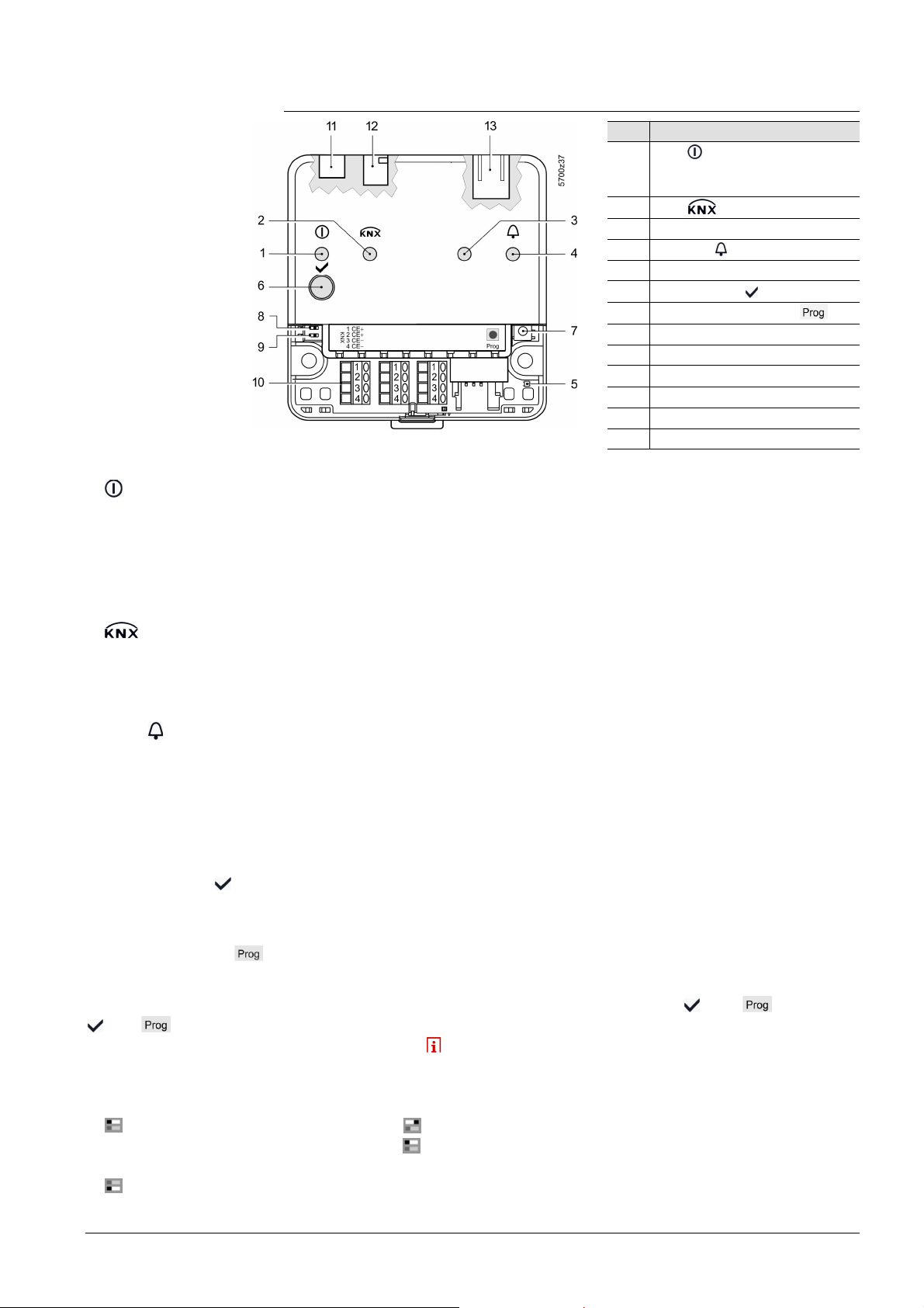
1.2 Web Server display and operating elements
Overview
LED displays
1 (red/green/orange)
2 (green)
Pos Designation
1 LED Operation, portal
connection display and "Energy
indicat or"
2 LED
3 LED field bus 2 (reserve)
4 LED fault
5 LED addressing mode
6 Remote button
7
Addressing mode button
8 "Message suppression" switch
9 Switch 2 (no function)
10 KNX bus connection terminals
11 Operating voltage connection
12 USB connection Mini-B
13 Ethernet connection, RJ45 plug
· Dark No operating voltage DC 24 V
· Steady red Web Server starts operating system
· Flashing red Web Server starts application
· Steady green Web Server operational, "Energy indicator" = "Green leaf"
· Steady orange Web Server operational, "Energy indicator" = "Orange leaf"
· Flashing Web Server operational, connected to portal
green / orange (LED 0.8 s on, 0.2 s off)
· Dark No bus power
· Lit KNX operational
· Flashing Communication on KNX
3 Field bus 2 (reserve)
4 Fault
(red)
5 Addressing mode (red)
Operating buttons
6 Remote button
7 Addressing mode
Button combinations
and
Switches
Message
8
suppression
· Dark No function
· Dark No fault (normal operating state)
· Lit Acknowledged fault
· Flashing Unacknowledged fault
· Dark KNX addressing mode off
· Lit KNX addressing mode o
· Short (< 2 s) Acknowledges fault message
· Long (> 6 s) Sends system report to fault e-mail Receivers
(not to consumption data and "Energy indicator" Receivers)
· Short (< 2 s) Press once: KNX addressing mode on
Press again: KNX addressing mode off
· Long (> 6 s) Simultaneously pressing the buttons
and restores
defaults
All configuration data and settings are reset. The
device list, plant diagrams, and unsent messages are
deleted. History data is not deleted.
· Position ON
Sending messages is suppressed
· Position OFF Sending messages permitted
9
DIP switch 2
Siemens Web server OZW772... V6.0 CE1C5701en
Building Technologies Overview 2015-10-12
· Switch settings No function
9 / 176
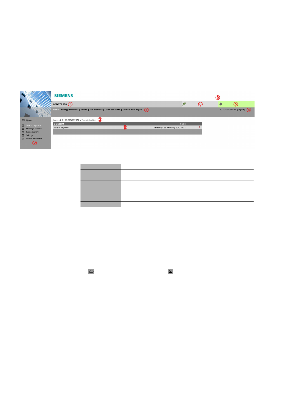
1.3 User interface
Plant state
Plant state
A web browser is used to access the user interface for the Web Server.
· The Web Server provides text-based operation of the Web Server and
connected Synco devices as a standard (Section 4).
· You can also set up visualized operation (Section 5).
The following describes the display areas for the text-based standard user interface
(display areas for visualization are outlined in Section 5).
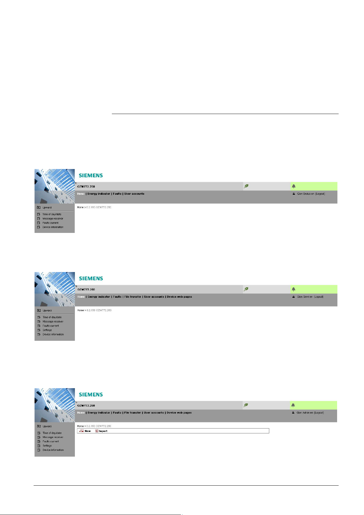
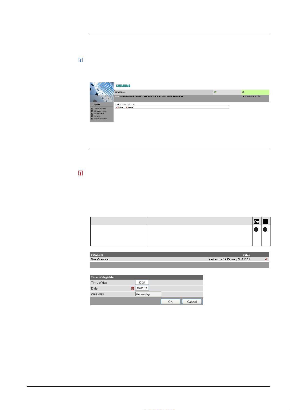
The main window is sub-divided into various areas.
Primary navigation
Secondary navigation
Command sequence
User
fault
The following functions are selected via primary navigation:
Home Menu-based plant and device operation.
Energy indicator Display and operate "Energy indicator" data points.
(displayed only is controller is connected with an Energy indicator)
Faults Display system faults.
File transfer Download consumption data and event history,
upload documents, logos and system definitions.
User accounts User administration.
Device web pages Create device list and operating pages.
Device operation (via home) queries devices and their operating pages via
secondary navigation (menu tree). As of OZW-Version 5.0, KNX pages defined in
ETS are displayed here too.
The path displays the workflow starting at the main menu to the open operating
page. Simply click at any point on the path to return to that location.
This field shows the currently logged-in user. Clicking [Logout] ends the current
session. The session remains active until logout. When connecting via the portal
the symbol is displayed instead of the symbol and the user’s email address
is displayed rather than the user name.
The "Plant state fault" field is displayed permanently:
· Green field: No fault
· Red field: Plant fault
Click the "Plant state fault" field to display all faults in the plant.
Energy indicator
10 / 176
Siemens Web server OZW772... V6.0 CE1C5701en
Building Technologies Overview 2015-10-12
The "Plant state Energy indicator" field is displayed permanently:
· Green leaf: All "Energy indicator" data points are always within
their "green limits", i.e. "within the green/allowed range".
· Orange leaf: One or multiple "Energy indicator" data points are
outside their "green limits"
Clicking the "Plant state Energy indicator" field opens the "Energy indicator"
function.
Plant name
Displays plant name as entered.
Display
Logo area
End user
The display range displays content corresponding to the selected function via
primary and secondary navigation.
Shows Logo 1 and Logo 2.
1.3.1 User levels
Displays and operates based access level for the logged on user:
· Operate end user data
· Operating of KNX S-Mode devices
· Fault overview
· Administer own user account
Service
Administrator
Same as end user. In addition:
· Operate service data
· Documents, message history
Same as service. In addition:
· Create device list and web pages
· The toolbar to create plant web pages
· Administer all user accounts
11 / 176
Siemens Web server OZW772... V6.0 CE1C5701en
Building Technologies Overview 2015-10-12
1.4 Symbols, notations, abbreviations
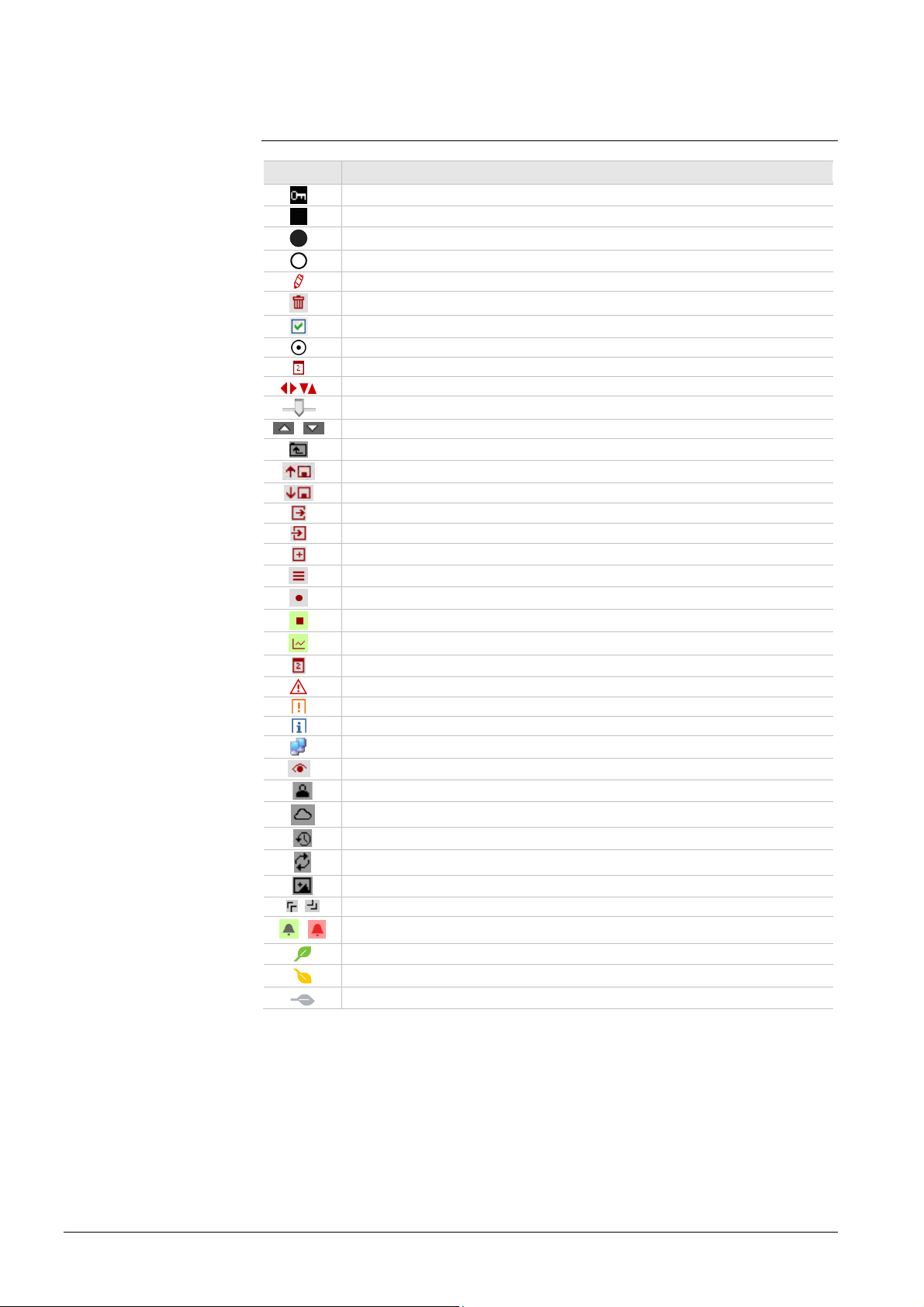
1.4.1 Symbols
Symbols
Symbol Meaning
Data point at the service level
Data point at the end user level
Read/write data point; the setting value can be changed
Read-only data point; the value cannot be changed
Link to entry field
Delete object
Checkbox
Selection box
Cal en dar
Arrows to incrementally adjust values
Adjustment tab
/ Arrow to display sort order
Up
File upload (to Web Server)
File download (from Web Server)
Export file
Import file
Add data point
Move/sort data point
Start trending
Stop trending
Generate trend graph
Cal en dar for s el ecting the date
Safety note, intended to protect against misus e
Always obs erve/follow
Note; important information
Network c onnection
Link to device
User connected locally or via direct connection (fixed or dynamic IP address).
User c onnec ted via port al.
Message history
System definitions
Logos
, Switch over displays: Full view, partial view
/
Fault indication: Green field = no fault; red field = fault (alarm)
"Green leaf"
"Orange leaf"
"Grey leaf"
12 / 176
Siemens Web server OZW772... V6.0 CE1C5701en
Building Technologies Overview 2015-10-12

1.4.2 Notations
Path indications
IP address, domains
Buttons
Abbreviations
Paths are printed as follows:
· Web Server: Home > 0.2.150 OZW772.xx > Settings > Time of day/date.
· PC: Start > Settings > Network connections > Local Area Connection.
OZW772.xx stands for: OZW772.01 or
OZW772.04 or
OZW772.16 or
OZW772.250
Enter in the browser address line:
· IP address: 192.168.2.10
· Domain: www.siemens.com
· Portal: https://www.siemens-syncoic.com
Buttons depicted as follows: [ Add ]
1.4.3 Abbreviations
Auto MDI-X Auto Medium Dependent Interface – Crossed.
COV Change of value
ECA Energy Cost Allocation
HTTP Hyper Text Transfer Protocol
HTTPS Hyper Text Transfer Protocol Secure
IP Internet Protocol
KNX Konnex
LAN Local Area Network
NAT Network Address Translation
PAT Port and Address Translation
RNDIS Remote Network Driver Interface Specification
SMTP Simple Mail Transfer Protocol
STP Shielded Twisted Pair
TCP Transmission Control Protocol
TLS Transport Layer Security
UPnP Universal Plug and Play
USB Universal Serial Bus
UTP Unshielded Twisted Pair
Web API Web Application Programming Interface
The glossary, Section 11.4, contains detailed explanations of terms and
abbreviations.
13 / 176
Siemens Web server OZW772... V6.0 CE1C5701en
Building Technologies Overview 2015-10-12

2 Commissioning
This section describes how to commission the Web Server.
2.1 Prerequisites
General
Notes
Portal commissioning
requirements
The following conditions must be met to commission the Web Server:
· The Web Server is mounted and wired (see Installation instructions, G5701).
· The connected KNX devices are commissioned.
· The KNX devices have a valid KNX address [1...253] are operating.
Note: Web Servers are delivered with KNX address 150. As a result KNX
address range [1…253], except for 150, applies to all other devices.
· Bus power supply to the KNX bus is available.
· The Web Server or another KNX device is the clock master on KNX.
· The Web Server automatically receives its IP address from the router when the
DHCP client is switched on. The address without router is: 192.168.2.10
(factory setting, see Section 8.1.2)
· Connecting a SmartPhone App to a Web Server makes sense only after the
Web Server is fully commissioned.
The following is required to commission the Web Server on the portal:
· The Web Server is connected to the Internet
The Web Server automatically registers on the portal.
The operation LED starts to flash green / orange as soon as the Web Server is
connected to the portal.
Local commissioning
requirements without
portal
Operating notes
The following is required to commission the Web Server:
· A PC/laptop and a web browser commission Web Server via an USB interface.
The RNDIS driver must be installed to connect via USB. IP address USB:
192.168.250.1 (cannot be changed). The address range 192.168.250.1 -
192.168.250.255 cannot be used for Ethernet and is reserved exclusively for
USB.
· The RNDIS driver is automatically installed when connecting via USB if the
PC/laptop is connected to the Internet (as long as the Microsoft online update
service is enabled). The RNDIS driver can be installed manually if there is no
connection to the Internet (see Section 11.3.3)
· The RNDIS is supplied on the Web Server at http://<IP-Adresse>/drivers/
· To navigate, always start with primary navigation, then use the secondary
navigation to select the desired menu item.
· Return: Click
"Upward" or navigate via the path or primary navigation.
14 / 176
Siemens Web server OZW772... V6.0 CE1C5701en
Building Technologies Commissioning 2015-10-12
2.2 Getting started
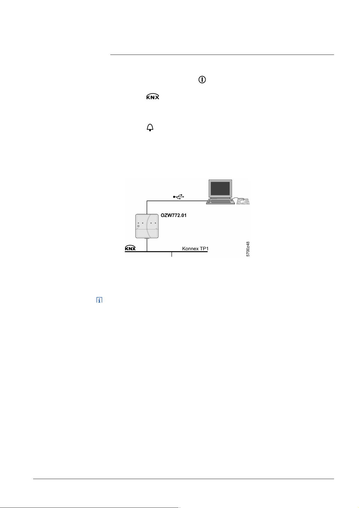
2.2.1 Turn on Web Server
Turn on Web Server
Connect the Web Server to the power supply and connect it to the PC:
1. Connect power supply to turn on power on Web Server. The Web Server is
operational, when the green
2. Check additional displays:
· LED
Green light if the KNX bus power supply is available. Check KNX bus
wiring and setting for bus power supply on the KNX devices if no bus
power supply is available.
· LED
Dark if no fault pending. You can troubleshoot pending faults later (see
Section 4.3).
3. Plug the supplied USB cable into the Web Server and the PC and start up
the PC. The PC recognizes the Web Server as a USB device.
Otherwise, the RNDIS is still not installed.
LED is lit.
Note
4. The RNDIS driver is installed automatically if the PC is connected to the
Internet and no RNDIS driver is installed as long as the Microsoft online
update is enabled. Follow the instructions for the installation program.
You can also manually setup the RNDIS driver (see Section 11.3.3).
15 / 176
Siemens Web server OZW772... V6.0 CE1C5701en
Building Technologies Commissioning 2015-10-12
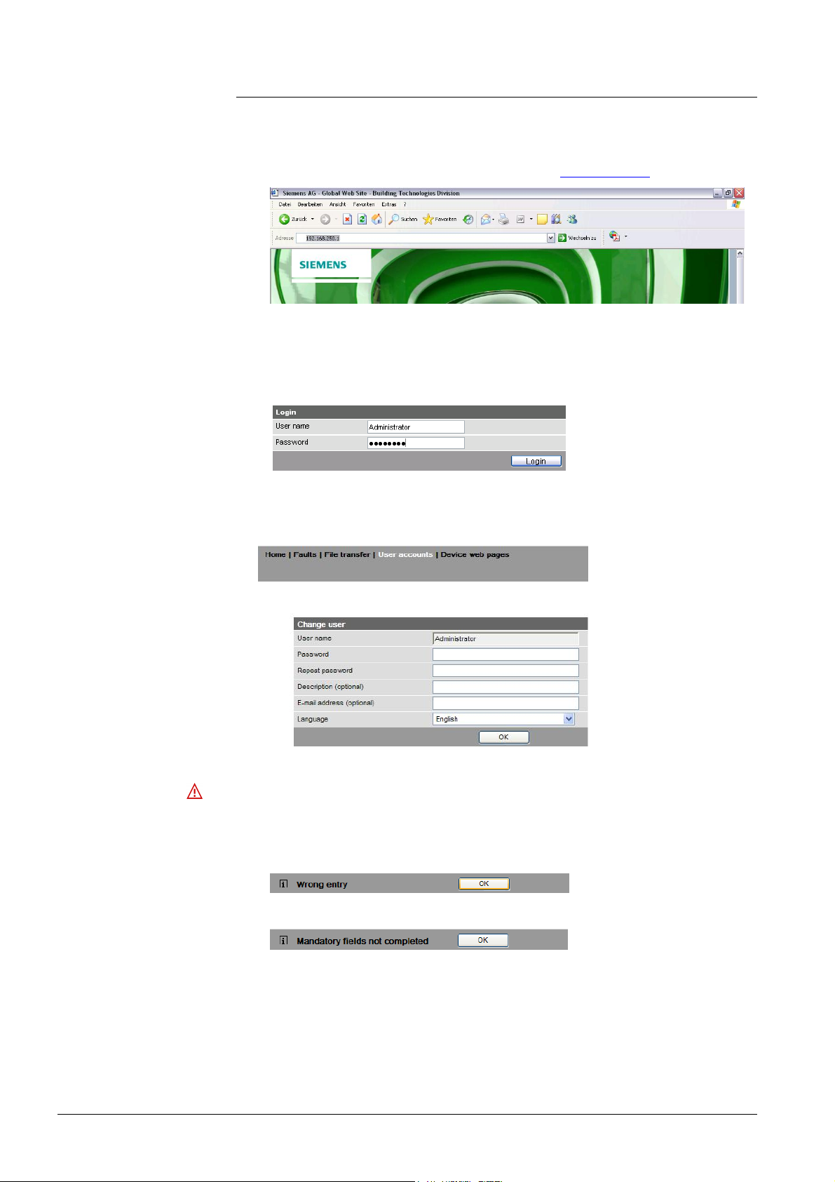
2.2.2 Log into Web Server
Log on
A PC with USB interface and web browser is used to commission the Web Server.
1. Start web browser.
2. In the address line, enter the USB IP address (192.168.250.1).
3. First time Login
· User name Administrator
· Password to V5.2(Password): Password
· Password as of V6.0 (Password): Password.1
4. Click [ Login ] to finish.
5. After logging on the first time, the dialog box is displayed to define a new
password.
·
Important note
· A new password must be defined the first time you log in (you can also
change the language).
· You cannot exit the dialog box if you do not define a new password (i.e. not
equal to "Password or Password.1") and the following note is displayed:
· The following message is displayed if you fail to fill out all required fields:
16 / 176
Siemens Web server OZW772... V6.0 CE1C5701en
Building Technologies Commissioning 2015-10-12

Password and user
name
Observe capitalization when entering the password.
The message "Entry incorrect" is displayed when entering an incorrect password.
Minimum password
strength
The password strength is checked when entering the password and a progress bar
displayed. The bar is orange is the password is week. It changes to green as soon
as the password is strong enough.
The following conditions must be met for a secure password:
· Minimum password length of 8 characters
· At least 1 capital letter
· At least 1 lowercase letter
· At least 1 number
· At least 1 special character
17 / 176
Siemens Web server OZW772... V6.0 CE1C5701en
Building Technologies Commissioning 2015-10-12
2.3 Administer user accounts
Administer user
accounts
Note
Change
administrator data
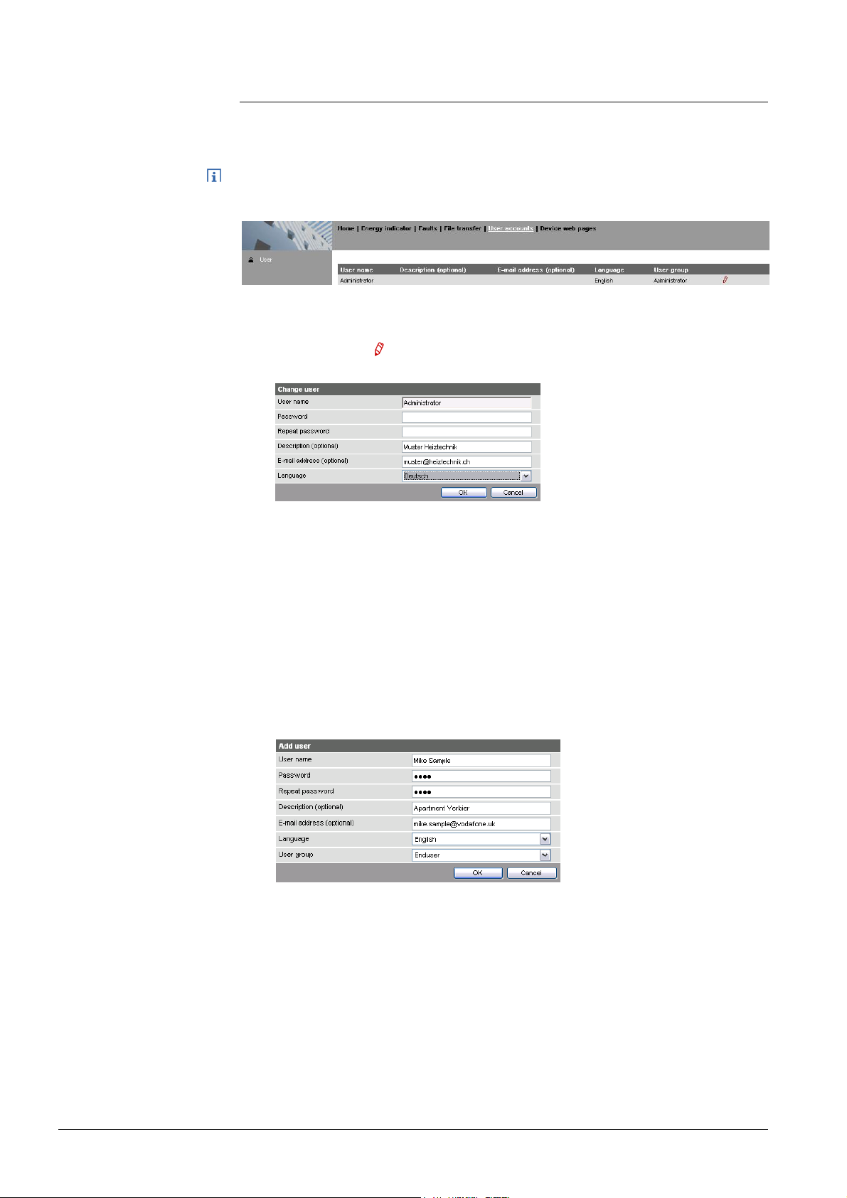
The "User Accounts" ("User accounts") menu changes the administrator password
at delivery and sets up additional user accounts.
The user account settings equally apply to access via Smartphone app and other
applications via Web API.
Procedure:
1. Click red pencil
The "Change user" dialog box opens.
2. Change administrator data:
- Password
- Repeat Password
- Description (optional)
- E-mail address (optional)
- Language: English
3. Close with [ OK ]
Add a new user
Procedure:
1. Click [ Add ]
Add user"
The "
dialog box opens.
2. Enter / Select user data:
- User name
- Password
- Repeat password
- Description (optional)
- E-mail address (optional)
- Language: English
- User group
3. Close with [ OK ]
18 / 176
Siemens Web server OZW772... V6.0 CE1C5701en
Building Technologies Commissioning 2015-10-12
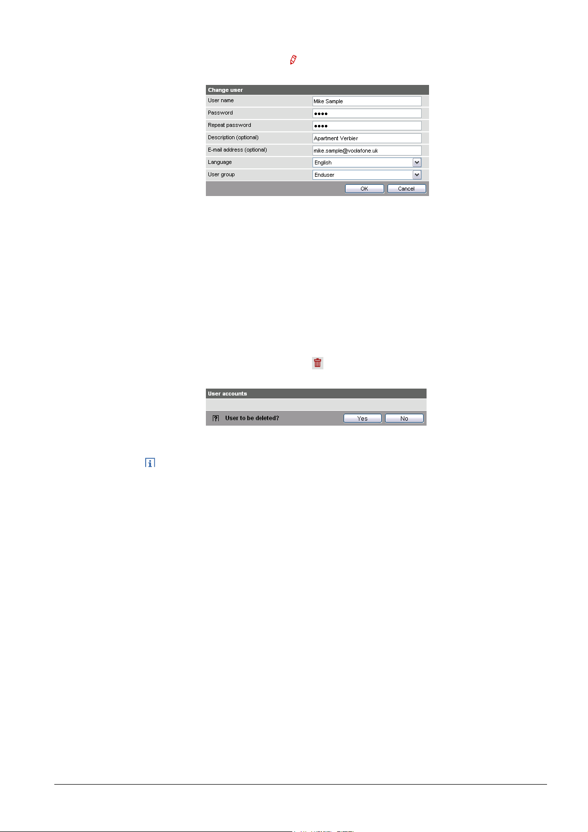
Change user data
Procedure:
1. Click the red pencil
Change user"
The "
2. Change user data:
- User name
- Password
- Repeat password
- Description (optional)
- E-mail address (optional)
- Language: English
- User group.
3. Close with [ OK ]
for the corresponding user
dialog box opens.
Delete user account
Notes
Procedure:
1. Click the red recycle bin
for the corresponding user.
The "User accounts" dialog box opens.
2. Click [ Yes ] to confirm "User to be deleted?".
· The administrator account cannot be deleted. The name "Administrator" and
user group "Administrator" cannot be changed. You may, however, add user
accounts with administrator rights.
· You can only add new users and delete existing ones on the "Administrator"
user level.
· Changing other user accounts is reserved to the "Administrator" user level.
· A secure password is comprised of letters, numbers and special characters,
is at least 20 characters in length and does not include a name or words from
dictionaries.
19 / 176
Siemens Web server OZW772... V6.0 CE1C5701en
Building Technologies Commissioning 2015-10-12
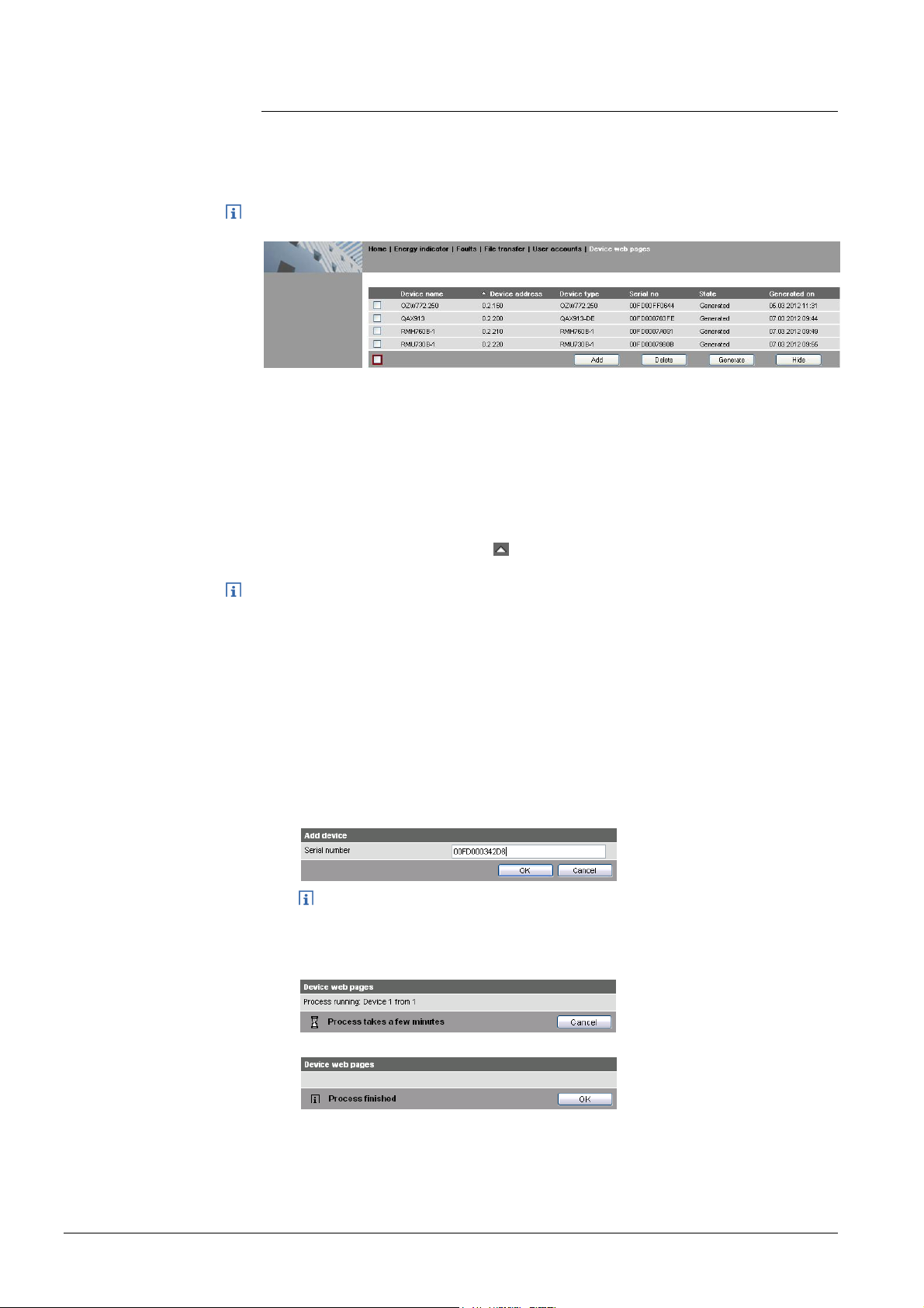
2.4 Create device web pages
Create device
websites
Note
The associated devices must be recorded and the device websites generated
before operating the Web Server and the Synco devices. Use the "Device web
pages" menu.
Device web pages can only be created on the "Administrator" user level.
Linked devices are listed in a table with the following information:
· Device name
· Device address
· Device type
· Serial number
· State
· Generated on
You can sort the table by clicking
Notes
Add devices
· The Web Server itself is already in the device list.
· Only added devices are monitored.
· Only generated devices can be operated.
· Device web pages can only be generated on the "Administrator" user level.
· Changes to settings of the connected Synco device may require that the device
web pages be recreated or updated to apply changes from web operation.
· You must delete and re-add to replace a Synco device.
Procedure:
1. Click [ Add ]
2. Enter serial number.
The serial number is located on the type label for Synco devices.
3. Confirm with [ OK ]
The Web Server searches for the device with the corresponding serial
number. It appears in the device list if found.
20 / 176
Siemens Web server OZW772... V6.0 CE1C5701en
Building Technologies Commissioning 2015-10-12
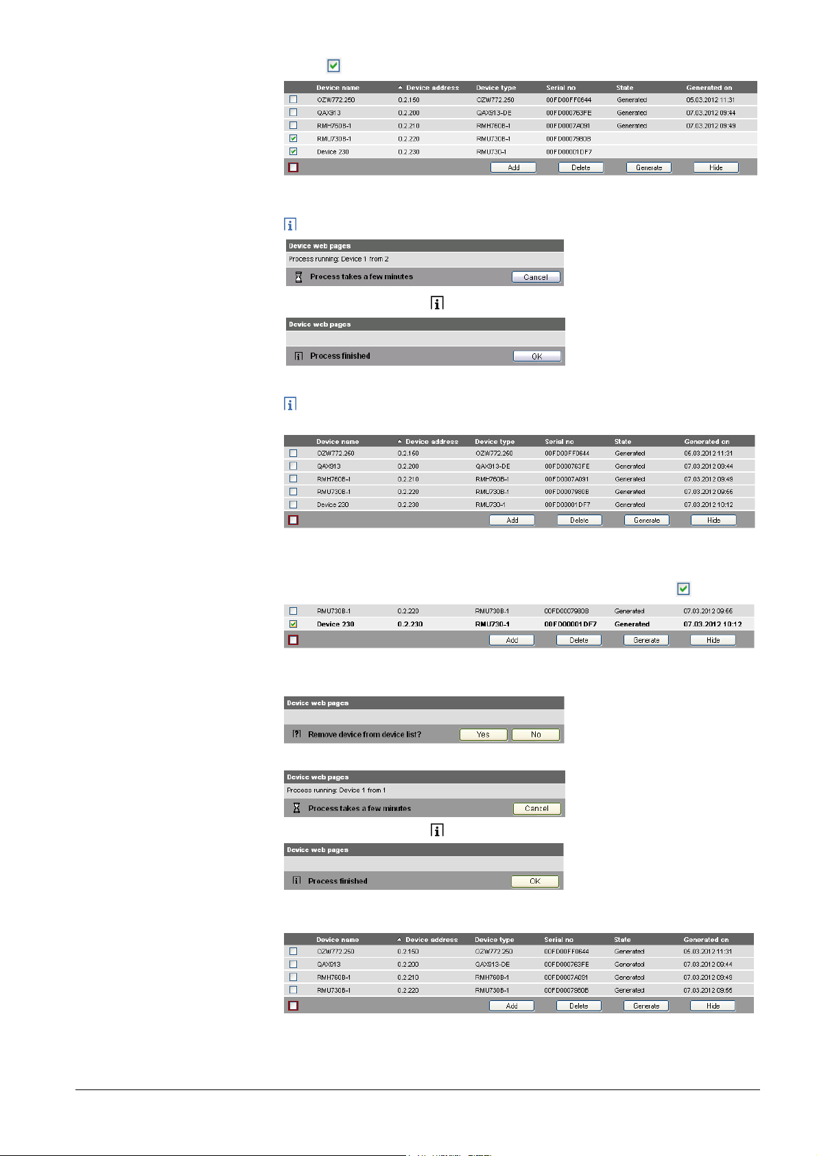
4. Select
devices whose web pages you want to create.
5. Click [ Generate ]
Device web pages are generated.
The process may take a few minutes.
6. Wait until the message " Process finished" is displayed.
7. Close with [ OK ]
The device list for the Web Server and Synco devices displays status
"Generated".
Delete device
Procedure:
1. Select the Synco device you want to remove from the device list
2. Click [ Delete ]
3. Confirm with [ Yes ]
4. The Web Server removes the device from the device list.
5. Wait until the message " Process finished" is displayed.
6. Click [ OK ] to confirm.
The device is deleted from the device list.
21 / 176
Siemens Web server OZW772... V6.0 CE1C5701en
Building Technologies Commissioning 2015-10-12

Update
device web pages
The following changes to user defined texts result in outdated device web pages:
· Menu tree names *, e.g. Message receiver 1…4.
· Web Server plant names.
· Plant names for Synco devices (e.g. QAX913).
The impact and restore differ for the three changes mentioned above based on
internal KNX data storage.
Change Device list (device web pages) Texts in sec. navigation Generate/
Update
Menu tree names *, e.g.
Device name Status Menus Device nodes
n/a Outdated Outdated n/a Required no
Delete, Add
Message receiver 1…4
Web Server plant name Current Generate Current Outdated Required no
Plant name for Synco
Outdated Generate Current Outdated ** No Required
device(s)
* Menu tree names are user defined texts displayed in secondary navigation (menu tree)
** Even after generate
Notes
· You can update device web pages on user levels "Administrator" and "Service".
· Click "Update" on the service level and "Generate" on the Administrator level to
start updating (see "Create device web pages").
· You can only delete a Synco device on the "Administrator" user level.
Tip
When deleting or adding a Synco device (see above for description of workflow),
we recommending copying (select and right-click: Copy) the serial number to the
clipboard prior to deleting.
22 / 176
Siemens Web server OZW772... V6.0 CE1C5701en
Building Technologies Commissioning 2015-10-12
2.5 Web Server settings
The "Home" menu is used to set the Web Server. The Web Server and then the
corresponding operating page are selected in secondary navigation.
Notes
Time of day/date
Power reserve
· The settings depend on the user level.
· Only data points that can be read are described in this section.
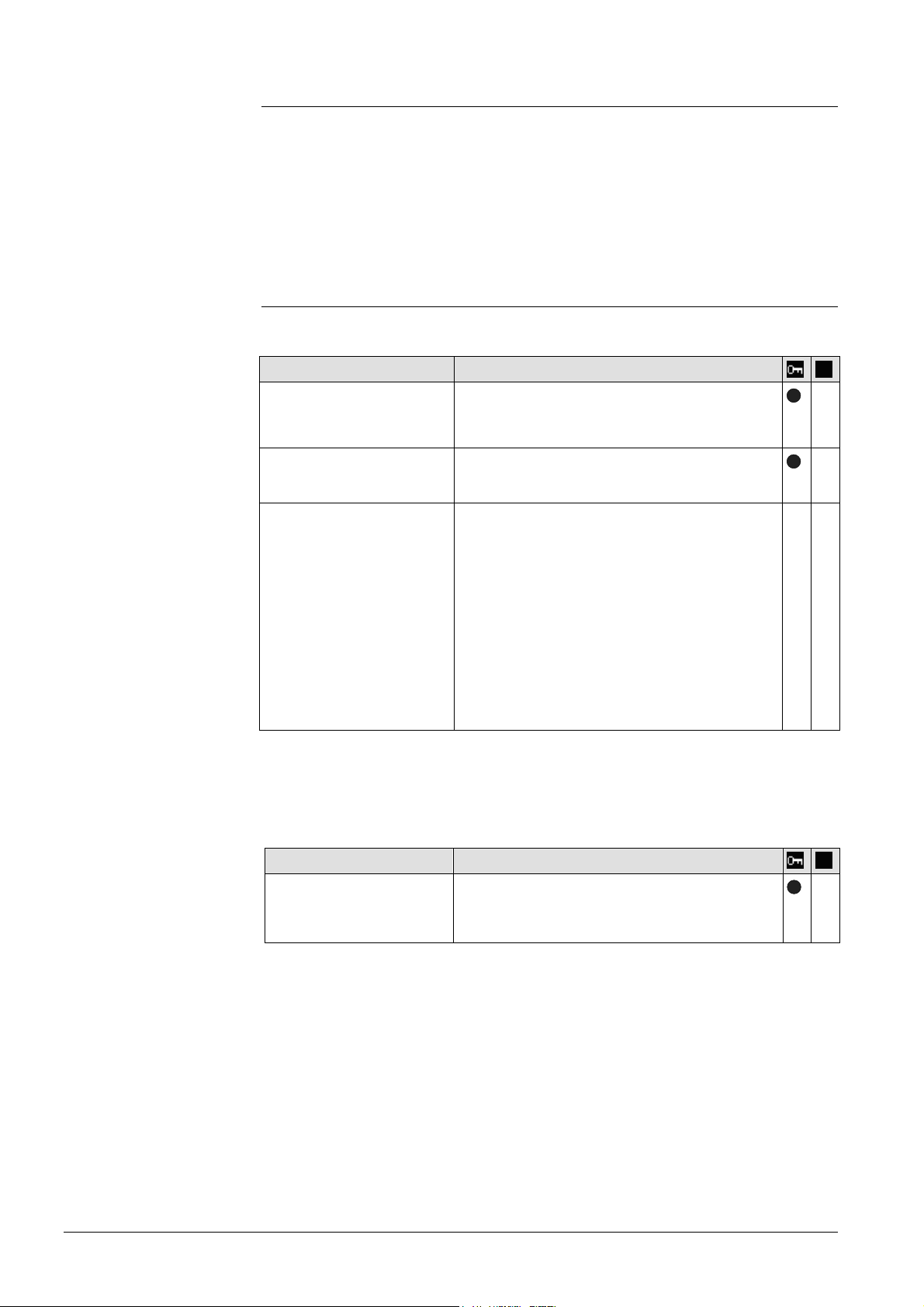
2.5.1 Operating page settings "Time of day/date"
Time/data can be set during operation.
Path: Home > 0.2.150 OZW772.xx > Time of day/date
The clock has a backup battery for at least 72 hours. The clock continues to run
after power failure for the duration of the backup battery.
Both date and time are reset in case of an extended interruption.
· It is corrected automatically if the time is synchronized to the master clock on
the KNX bus (see Section 2.5.3.3).
· Otherwise, both date and time must be reset.
Data point Explanation, example
Time of day/date
Default val: 00:00 1.1.2005
Setting val: Time of day/date
The setting values are derived from the current
time clock and the current date. Weekday is
calculated automatically.
23 / 176
Siemens Web server OZW772... V6.0 CE1C5701en
Building Technologies Commissioning 2015-10-12
Language and
code number
2.5.2 Operating page "Faults current"
Local faults and faults in system are displayed under "Faults current".
Path: Home > 0.5 OZW672… > Faults current
A description of faults is available in Section 4.3,"Faults"
2.5.3 Operating page "Settings"
2.5.3.1 Web Server
Path: Home > 0.2.150 OZW772.xx > Settings > Web Server
Data point
Language
Default val: English
Setting val: see example
Code
Default val: 01
Setting val: max. 20 charact.
Reset admin password *
Default val: No
Setting val: Yes
* with PC software ACS790 only.
2.5.3.2 Time of day/date
Explanation, example
Web Server language: Is used for Web Server
—
fault texts, message history, messages and
system reports.
Access code for PC Software ACS790. —
If you do not know the administrator password
for the Web Server, setting value "Yes" again
*—*
—
provides access to the Web Server via the
administrator password "Password".
"Password or Password.1" is possible again
(Administrator password for delivery of
devices to Version 5.2 = "Password", for
devices as of Version 6.0 = "Password.1").
Setting value "Yes" is a temporary state, i.e.
the setting value automatically goes to "No"
after ca. 2 seconds.
Time zone
24 / 176
Siemens Web server OZW772... V6.0 CE1C5701en
Building Technologies Commissioning 2015-10-12
Path: Home > 0.2.150 OZW772.xx > Settings > Time of day/date
Data point
Time zone
Default val: GMT +01:00
Berlin, Rome
Setting val: misc. Time zones
Explanation, example
The time zone setting value is based on UTC
(GMT). The time zone also defines daylight
saving time / standard time changeover.
—
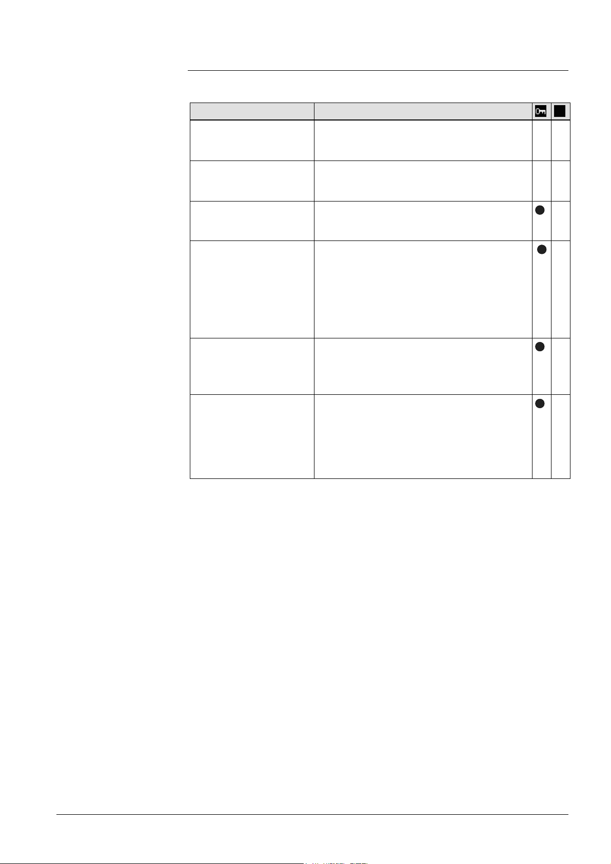
2.5.3.3 Communication
KNX
Path: Home > 0.2.150 OZW772.xx > Settings > Communication > KNX
Data point
Range
Explanation, example
Displays the range within the KNX bus.
e.g. 0 for address 0.2.150
The range is set in ETS.
Line
Display of line within the KNX bus.
e.g. 2 for address 0.2.150
The line is set in ETS.
Device address
Default val: 150
Setting val: 1... 253
Time synchronization
Default value: Slave on bus
Setting values: Slave on Bus
Quartz
Set device address. The device address must
be unique within the same KNX line.
Defines time synchronization on the Web
Server. Default value "Slave on bus": Clock
master is available on the KNX network.
Setting value "Quartz": The clock is
synchronized with quartz on the Web Server.
Web Server operates a clock master or
autonomously.
Clock time mode KNX
Default val: Autonomous
Setting val: Autonomous/Master
"Slave" for "Time synchronization" = "Slave on
bus".
For "Time synchronization" = "Quartz", can
selected between "Autonomous" or "Master".
Clock slave remote adj
KNX
Default val: Yes
Setting val: Yes / No
Setting value is important for "Time
synchronization" = "Slave on bus".
For "Clock slave remote adj KNX" = "Yes" the
time clock for the clock master on the KNX
network can be changed via the time clock for
the Web Server.
—
—
—
—
—
—
—
—
The following data points are information parameters. They are described in
Section 4.2.3, "Web Server diagnostics":
· Maximum number of devices
· Current number of devices
· Last change
25 / 176
Siemens Web server OZW772... V6.0 CE1C5701en
Building Technologies Commissioning 2015-10-12
Ethernet
Path: Home > 0.2.150 OZW772.xx > Settings > Communication > Ethernet
Notes
· Enter these settings if you intend to operate the Web Server on a local area
network (LAN) or via the Internet.
· Alternative settings are available for operating with DHCP client switched off.
· Entries for the various network topologies are described in Section 8.1.
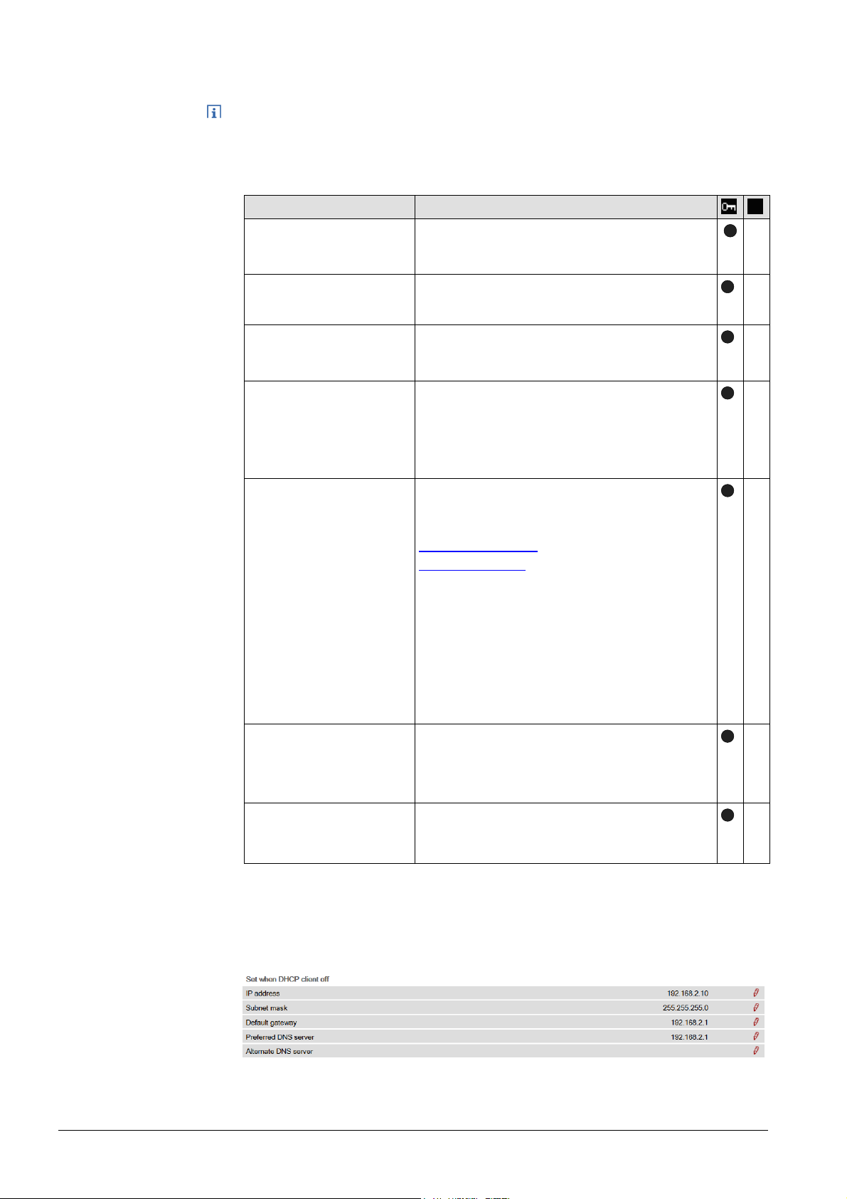
Data point
DHCP client
Default val: On
Setting val: Off, On
IP address
Default val: 192.168.2.10
Setting val: IP address
Subnet mask
Default val: 255.255.255.0
Setting val: IP address
Default gateway
Default val: 192.168.2.1
Setting val: IP address
Explanation, example
Service automatically getting the Web-Server's
IP network configuration automatically rom the
router; see Section 8.1.2.
Web Server IP address. Does not require
setting if "DHCP client = On".
The IP subnet mask sets the size of the
subnet. Does not require setting if "DHCP
client = On".
The standard gateway represents the interface
between the local and public network. You
typically enter the IP address for the router
here. Does not require setting if "DHCP client
= On".
Preferred DNS server
Default val: 192.168.2.1
Setting val: IP address
The DNS server (domain name system) on the
Internet connects a globally valid name to a
domain with an IP address (e.g. domain
www.siemens.com with IP address
146.254.191.150).
The setting corresponds to the IP address for
the next router or DNS server that recognizes
for its part a queried name (domain) or
another DNS server.
The setting is typically identical to the setting
for the standard Gateway. Required to send emails. Does not require setting if "DHCP client
= On".
Alternate DNS server
Default val: (blank)
Setting val: IP address
The alternative DNS server is only defined for
redundant systems. Settings are typically
empty. Does not require setting if "DHCP client
= On".
UPnP localization
Default val: Ethernet
Setting val: ---, Ethernet, USB
The Web Server registers its presence in the
network via the Universal Plug and Play
(UPnP) service.
—
—
—
—
—
—
—
The data point "Physical address" is an information parameter. It is described in
Section 4.3, "Faults".
If the DHCP client is switched off, the corresponding settings must be entered
manually.
E-mail
26 / 176
Siemens Web server OZW772... V6.0 CE1C5701en
Building Technologies Commissioning 2015-10-12
Path: Home > 0.2.150 OZW772.xx > Settings > Communication > E-mail
Notes
· Enter these settings if the Web Server sends e-mails (report faults / send
consumption file).
· Additional information on e-mail settings is available in Section 8.2.
· Automatically negotiate the securest connection:
TLS mode is selected automatically if the device sending the email and the
email provider support TLS.
Data point
Address mail server
Default val: smtp.example.c om
Setting val: max. 49 characters
Port number mail server
Default val: 25
Setting val: 1…65535
E-mail address sender
Default val: ozw772@ example.com
Setting val: max. 49 characters
Authentication mail server
Default val: No
Setting val: No/Yes
User name
Default val: (blank)
Setting val: max. 49 characters
Password
Default val: (blank)
Setting val: max. 49 characters
Signature line 1…10
Default val: (blank)
Setting val: max. 49 characters
Explanation, example
Contact the Internet service provider for the
mail server's address (IP address) or name
(domain). Often referred to as the outgoing
mail server or SMTP server instead of mail
serv er.
Port number 25 is default for the mail
server (and does not normally require
change).
The setting corresponds to the e-mail
address of the Web Server.
The e-mail address is displayed in the
"From" field of each e-mail.
Select Yes for mail server access with
authentication.
In this case, user name and password (see
next two data points below) are required.
User name and password help authenticate
each e-mail via the mail server.
Password and user name help authenticate
each e-mail via the mail server.
Signature lines are transmitted with the email. It identifies the sender, e.g. the plant's
Internet address.
—
—
—
—
—
—
—
USB
UPnP localization
Path: Home > 0.2.150 OZW772.xx > Settings > Communication > USB
Data point
UPnP localization
Default val: USB
Setting val: ---, Ethernet, USB
Explanation, example
The Web Server registers its presence in the
network via the Universal Plug and Play
(UPnP) service.
Web Server registers its existence in the USB network, when
—
· "UPnP localization = USB" is set and
· The connection between PC/laptop and the Web Server is active via USB.
27 / 176
Siemens Web server OZW772... V6.0 CE1C5701en
Building Technologies Commissioning 2015-10-12
Services
Path: Home > 0.5 OZW672... > Settings > Communication > Services
Data point Explanation, example
ACS access
Default value: On
Setting values: On/Off
Permits access by ACS operating software to
the Web Server (only possible via direct
connection – not possible via the portal). For
security reasons, ACS access should be
switched off after commissioning.
Web access via http
Default value: Off
Setting values: On/Off
Permits communication using the http protocol
rather than the secured https connection.
Siemens recommends https. The user is
responsible for using http.
UPnP localization
Default value: Ethernet
Setting value: ---, Ethernet,
USB
ETS access via
KNXnet/IP
Default value:On
Setting values:On/Off
Portal connection
Default value: On
Setting values: On/Off
Automatic
log off
Default value: On
Setting values: On/Off
The Web-Server registers its existence in the
corresponding network using the Universal
Plug and Play (UPnP) service.
Permits access to the plant using ETS software
via KNXnet/IP (using direct connection only –
not possible via portal)
"On" enables data exchange with the portal. No
data is exchanged under "Off".
The connection to Web Server automatically
times out after 24 hours.
—
—
—
—
—
—
Message receivers 1…4
2.5.3.4 Message receivers
Data points are available for function checks of message receivers. They are
available under the following path:
Path: Home > 0.5 OZW772... > Settings > Message receivers
The use of these data points (test message receivers, send system report, reason,
message suppression) is described in Section 2.7, Functional check.
Message receivers must be defined if the Web Server sends fault messages via
email.
Settings can be made separately for 4 message receiver:
Path: Home > 0.2.150 OZW772.xx > Settings > Message receiver >
28 / 176
Siemens Web server OZW772... V6.0 CE1C5701en
Building Technologies Commissioning 2015-10-12
Data point Explanation, example
Message receiver 1…4
Def' value: (mess age receiver x)
Setting values: max. 20
characters
Message receiver 1…4 is a name (text) and
is displayed in the web browser. You must
run "generate" to display the change (for the
workflow, see Section "Refresh device web
pages" in Section 2.4).
—
Send messages
Notes
Receiver type
Default value: --Setting values: --, E-mail
All Receiver types are available:
"---": No messages to this message receiver.
"E-mail": Configure message receiver for e-
—
mail.
Fault priority
Default value: All
Setting values: All,
Only urgent ones
Email address
Default value: message receiver
@example.com
Setting values:max. 49characters
Number of messages for
send
The setting value "Only urgent ones" acts as
a filter for sending fault messages.
The setting value must match the e-mail
address of the message receiver.
Number of messages to be transmitted at
next send.
—
—
— —
The number of messages pending is available under "Number of messages for
sending".
A time frame can be defined during which messages can be sent for each receiver.
· The following settings are optional when restricting the time for sending
messages (default settings: No restriction).
· In general: Messages occurring outside the send periods are sent afterwards if
still pending during the send period.
Path: Home > 0.2.150 OZW772.xx > Message receiver > Message receiver 1…4
> Send messages
You can define time periods per weekday or special day when messages can be
sent to the message receivers.
Special days are defined via Holidays/special days.
Data point
Monday...Sunday,
Special day
Default val: Monday, 00:00
On …
Special day,
00:00 On …
Setting val: Monday - Sunday,
Special day
00:00 - 24:00 Off/on
Explanation, example
Each message receiver is assigned a time
switch to program max. 3 transmission times
for each weekday, i.e. periods during which
the Web Server can send messages.
The default value sends messages
throughout the entire period.
29 / 176
Siemens Web server OZW772... V6.0 CE1C5701en
Building Technologies Commissioning 2015-10-12
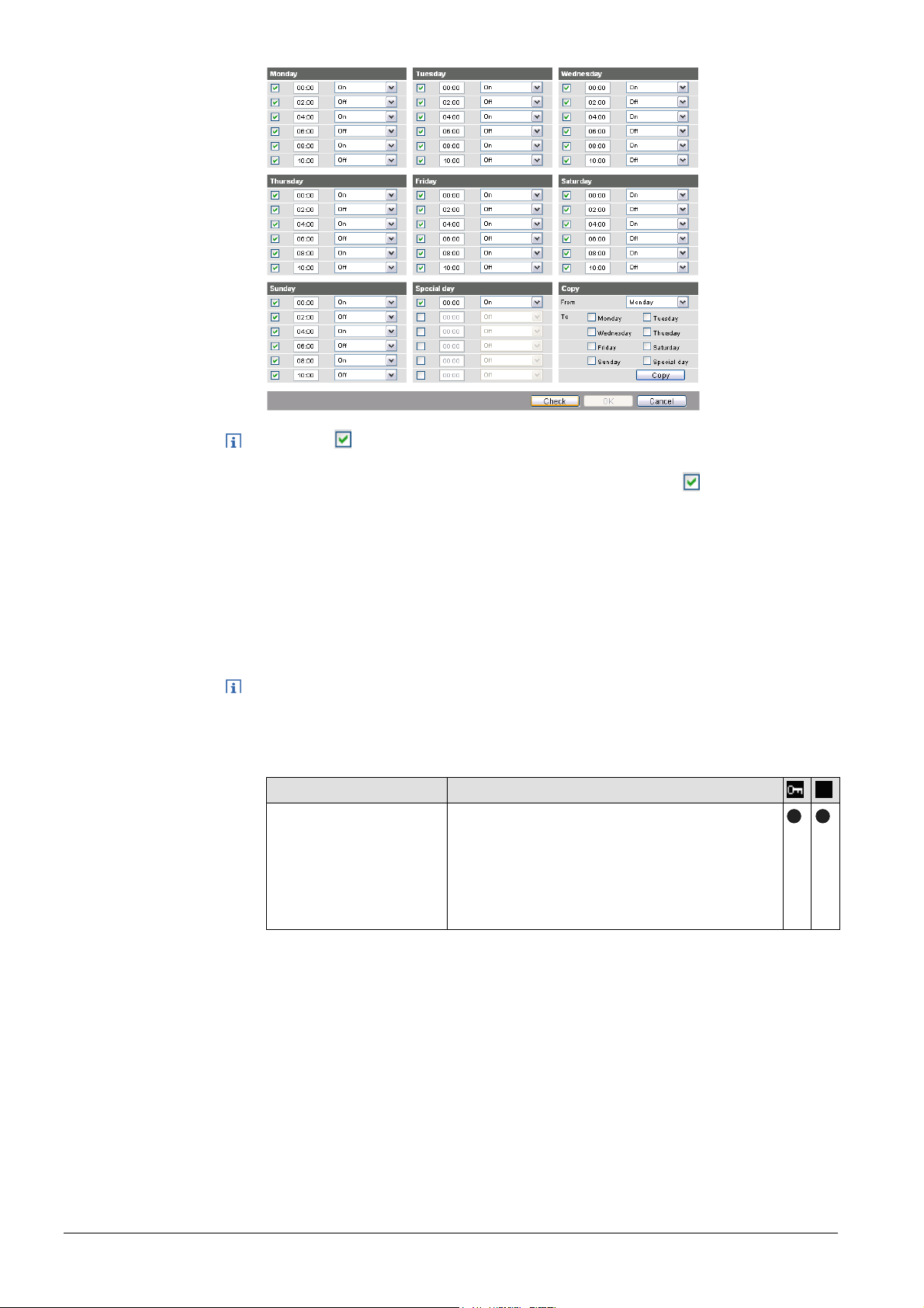
Notes
· Check to enable switching points.
· You can copy the switching times for a day of the week by
clicking [ Copy ] from one day to a selection of other days
· Click [ Check ] to sort and check the data before saving.
Holidays/special days
Notes
Path: Home > 0.2.150 OZW772.xx > Settings > Message receiver > Message
receiver 1…4
> Holidays/special days
No messages are sent during vacation/holidays. For special days, sending periods
are defined via "Send messages".
· General: Messages outside sending periods are resent during the next send
period.
· If a special day occurs during a holiday/vacation, the day is a special day.
· Holidays/special days can be set as recurring days each year.
Data point
Entry 1...16
Default val: --Setting val: Beginning
End
Reason
Annually
Explanation, example
Each receiver is assigned a yearly calendar to
enter holidays and special days. Holiday or
special day can be selected as Event. Data
and time can be used to indicated beginning
and end of period. Select "Annually" to repeat
the periods each year.
30 / 176
Siemens Web server OZW772... V6.0 CE1C5701en
Building Technologies Commissioning 2015-10-12
 Loading...