

Page 1

s
SC 7000 and SC 9000XL Patient Monitors
SC 9000XL Monitor 12in (30.5cm) Display
Service Manual Supplement Two
E331.E539U.640.10.03.02
ASK-A898-03-7600
EM Guidelines, 1997-04-02
Page 1 of 16
Page 2

Service Manual Supplement Two - 12in (30.5cm) Display SC 9000XL Patient Monitors
Table of Contents
1 Introduction . . . . . . . . . . . . . . . . . . . . . . . . . . . . . . . . . . . . . . . . . . . . . . . . . . . . . . . . . . . . . . . . . . . . 3
Chapter 3 . . . . . . . . . . . . . . . . . . . . . . . . . . . . . . . . . . . . . . . . . . . . . . . . . . . . . 3
2 Opening Monitor . . . . . . . . . . . . . . . . . . . . . . . . . . . . . . . . . . . . . . . . . . . . . . . . . . . . . . . . . . . . . . . . 3
2.1 Removing/Installing Side-Panels . . . . . . . . . . . . . . . . . . . . . . . . . . . . . . . . . . . . . . . . . . . . . . . . . 3
2.2 Separating Front Bezel Subassembly and Rear Housing Subassembly . . . . . . . . . . . . . . . . . . . 3
Figure 3-1 Locking Plates for Front Bezel Subassembly . . . . . . . . . . . . . . . . . . . . . . . . . . . . . . . . 3
Figure 3-2 Latch Locking Clips on Bottom of Monitor (only one shown) . . . . . . . . . . . . . . . . . . . . 4
Figure 3-3 Bottom Release Tabs for Front Bezel Subassembly . . . . . . . . . . . . . . . . . . . . . . . . . . . 4
Figure 3-4 SC 9000XL w/ 12in (30.5cm) Display . . . . . . . . . . . . . . . . . . . . . . . . . . . . . . . . . . . . . . 5
3 Replacing Subassemblies in Rear Housing . . . . . . . . . . . . . . . . . . . . . . . . . . . . . . . . . . . . . . . . . . . .5
3.1 Removing/Installing Funnel . . . . . . . . . . . . . . . . . . . . . . . . . . . . . . . . . . . . . . . . . . . . . . . . . . . . .5
Figure 3-5 Front Bezel Subassembly Components. . . . . . . . . . . . . . . . . . . . . . . . . . . . . . . . . . . . .6
4 Accessing Replaceable Subassemblies in Front Bezel Subassembly . . . . . . . . . . . . . . . . . . . . . . . . 6
Figure 3-6 Front Bezel Subassembly - Interior View, Plastic Frame Removed . . . . . . . . . . . . . . . . 7
Figure 3-7 Front Bezel Subassembly - Interior View, Retainer Plate Removed . . . . . . . . . . . . . . . 7
4.1 Removing Plastic Frame and Metal Retainer Plate . . . . . . . . . . . . . . . . . . . . . . . . . . . . . . . . . . . 8
4.1.1 Removing Plastic Frame and Metal Retainer Plate . . . . . . . . . . . . . . . . . . . . . . . . . . . . . . 8
4.1.2 Reinstalling Plastic Frame and Metal Retainer Plate . . . . . . . . . . . . . . . . . . . . . . . . . . . . . 8
4.2 Optical Encoder Subassembly . . . . . . . . . . . . . . . . . . . . . . . . . . . . . . . . . . . . . . . . . . . . . . . . . . .8
Figure 3-8 Optical Encoder Subassembly. . . . . . . . . . . . . . . . . . . . . . . . . . . . . . . . . . . . . . . . . . . . 8
4.2.1 Removing Optical Encoder Subassembly . . . . . . . . . . . . . . . . . . . . . . . . . . . . . . . . . . . . .8
4.2.2 Installing Optical Encoder Subassembly . . . . . . . . . . . . . . . . . . . . . . . . . . . . . . . . . . . . . . 9
4.3 Front Bezel PC Board . . . . . . . . . . . . . . . . . . . . . . . . . . . . . . . . . . . . . . . . . . . . . . . . . . . . . . . . . . 9
4.3.1 Removing Front Bezel PCB . . . . . . . . . . . . . . . . . . . . . . . . . . . . . . . . . . . . . . . . . . . . . . . .9
4.3.2 Installing Front Bezel PC Board . . . . . . . . . . . . . . . . . . . . . . . . . . . . . . . . . . . . . . . . . . . . 10
Figure 3-9 Display Subassembly . . . . . . . . . . . . . . . . . . . . . . . . . . . . . . . . . . . . . . . . . . . . . . . . . .10
4.4 Replacing Backlights . . . . . . . . . . . . . . . . . . . . . . . . . . . . . . . . . . . . . . . . . . . . . . . . . . . . . . . . . 11
4.5 Front Bezel/Lens Subassembly . . . . . . . . . . . . . . . . . . . . . . . . . . . . . . . . . . . . . . . . . . . . . . . . .11
4.6 Front Bezel Subassembly . . . . . . . . . . . . . . . . . . . . . . . . . . . . . . . . . . . . . . . . . . . . . . . . . . . . . 11
5 Closing Monitor . . . . . . . . . . . . . . . . . . . . . . . . . . . . . . . . . . . . . . . . . . . . . . . . . . . . . . . . . . . . . . . . 11
Appendix A . . . . . . . . . . . . . . . . . . . . . . . . . . . . . . . . . . . . . . . . . . . . . . . . . . 13
Figure A-5 Front Bezel Subassembly Components . . . . . . . . . . . . . . . . . . . . . . . . . . . . . . . . . 13
Table A-5 Front Bezel Subassembly - Replaceable Parts/Subassemblies . . . . . . . . . . . . . . . . 13
Figure A-6 Rear Housing and Funnel (Exploded View)l . . . . . . . . . . . . . . . . . . . . . . . . . . . . . . .14
Table A-6 Rear Housing and Funnel . . . . . . . . . . . . . . . . . . . . . . . . . . . . . . . . . . . . . . . . . . . .14
Page 2 of 16 Siemens Medical Systems, EM-PCS, Danvers ASK-A898-03-7600
9kXL_12inDspl.sm_sup.fm/06-99/kaupp
Page 3

SC 9000XL Patient Monitors Service Manual Supplement Two - 12in (30.5cm) Display
1Introduction
Chapter 3
5 Opening Monitor
Information in this supplement is applicable to only SC 9000XL monitors
factory equipped with a 12” (30.5cm) Display. It replaces information in the
SC 7000 and SC 9000XL Patient Monitors Service Manuals as indicated
below.Refer to either the printed version of the Service Manual (Art. No.
5949016E539U) and Supplement (Art. No.
version (Art. No. 5944090E539U)
N.B: The 12” (30.5cm) Display Front Bezel Subassembly is not
compatible with and cannot be installed on SC 7000 Monitors nor
on SC 9000XL Monitors factory equipped with 10.4” Displays.
Section references used in this supplement refer to the section numbers
in the printed Service Manual or CD-ROM. Changes impact primarily
Chapter 3, Repair, and Appendix A, Replacement Parts.
The impacted sections of Chapter 3 in the Service Manual are reproduced
below with appropriate changes. Some text and graphics that remain
unchanged from the material in the Service Manual, are included below as
a convenience. Sections NOT rewritten below, remain unchanged.
Before attempting to open the monitor, always do the following:
• Remove all attached modules and unplug all cables from the monitor.
• Disconnect all external power sources, remove external battery (if
installed), and remove back cover and unplug cable from main battery.
• Assure that both you and the work area are properly protected against
static-electricity discharge.
for all other service information.
5952416E539U) or to the CD -ROM
5.1 Removing/Installing Side-Panels
5.2 Separating Front Bezel
Subassembly and Rear
Housing Subass embly
Refer to procedure in Service Manual.
After left and right side panels have been removed, opening the monitor
consists of separating the front bezel and rear housing subassemblies. The
subassemblies are secured to each other by two locking tabs on the rear
housing at the bottom of the front bezel and two locking plates that secure
the top of the bezel to the rear housing (see Figure 3-7).
1
Figure 3-7 Locking Plates for Front Bezel Subassembly
ASK-A898-03-7600 Siemens Medical Systems, EM-PCS Danvers Page 3 of 16
9kXL_12inDspl.sm_sup.fm/06-99/kaupp
Page 4

Service Manual Supplement Two - 12in (30.5cm) Display SC 9000XL Patient Monitors
1 Place monitor in its upright position, with back of monitor facing you.
2 Remove and save two screws and locking plates (see a in Figure 3-7)
that secure top of Front Bezel Subassembly to rear housing.
1
2
Figure 3-6a Latch Locking Clips on Bottom of Monitor (only one shown)
3 Turn monitor topside down, as shown in Figure 3-6a if locking clips are
installed. If locking clips are not installed, go to step 5.
4 Peel off and save tape (a in Figure 3-6a) and remove and save locking
clips (s in Figure 3-6a) from the two latches on the bottom of the
monitor.
~
Figure 3-6 Bottom Release Tabs for Front Bezel Subassembly
5 Place monitor backside down with bottom of monitor facing you as
shown in Figure 3-6.
6 Press in firmly on thumb depressions on bottom of monitor to release
latches (see arrows in Figure 3-6), and pull up on bezel to slightly
separate left side of Front Bezel Subassembly from Rear Housing
Subassembly.
7 Carefully pull right-hand side of Front Bezel Subassembly up from rear
housing to unplug interfacing connector on back of front bezel PC
board from corresponding connector on main processing board.
8 Lift Front Bezel Subassembly off of rear housing to separate the two
subassemblies.
9 Store subassemblies in safe location as necessary.
Page 4 of 16 Siemens Medical Systems, EM-PCS, Danvers ASK-A898-03-7600
9kXL_12inDspl.sm_sup.fm/06-99/kaupp
Page 5

SC 9000XL Patient Monitors Service Manual Supplement Two - 12in (30.5cm) Display
2
Rear Housing Subassembly
Main Processor PCB Subassembly
Front Bezel Subassembly
6
7
2
4
5
5
3
1
Figure 3-8 (replacement) SC 9000XL w/ 12in (30.5cm) Display - Rear Housing Subasssembly, Main Processor
PCB Subassembly, and Front Bezel Subassembly
6Replacing
Subassemblies in
Rear Housing
6.1 Removing/Installing Funnel
ASK-A898-03-7600 Siemens Medical Systems, EM-PCS Danvers Page 5 of 16
9kXL_12inDspl.sm_sup.fm/06-99/kaupp
Locking tabs in the rear housing have been removed (see h in Figure 3-8)
to accommodate the 12in (30.5cm) Front Bezel Subassembly. With the
exception of a slight change in the remove/install procedure for the funnel,
however, all other procedures in this section of Chapter 3 in the Service
Manuals remain unchanged.
Note: Items
text references in the SC7000 and SC9000XL Service Manuals. Items
s,
s
that is removed for DirectNet operation of the Monitor.
The funnel has no locking tabs (s in Figure 3-8) but rather slides into
channels designed to provide a snug fit in the top of the rear housing.
• To remove the funnel, grasp it firmly in the area of the former tab slots
(
s
in Figure 3-8) and carefully work it out of the channels.
• To reinstall the funnel, slide it firmly into the guide channels, and seat
it against the lip on the back of the main PC board heat sink.
a, d, f, g
and h are references for this supplement. Item j is a label
and item g in Figure 3-8 correspond to
Page 6

Service Manual Supplement Two - 12in (30.5cm) Display SC 9000XL Patient Monitors
11
1
2
3
10
Figure 3-9 Front Bezel Subassembly Components.
4
5
(a in Figure 3-10)
8
12
6
7
1 of 2
15
14
9
2PL
13
7 Accessing
Replaceable
Subassemblies in
Front Bezel
Subassembly
7.1 Removing Plastic Frame and Metal Retainer Plate
7.1.1 Removing Plastic Frame
and Metal Retainer Plate
Replaceable components of the Front Bezel Subassembly are as follows:
• Optical Encoder Subassembly (
see Figure 3-11 on page 8)
• Front Bezel PC Board Subassembly (
• Front Bezel/Lens Subassembly (
installed membrane switches, lens, metal bezel frame, Siemens logo
and model labels, and feet)
• Backlight Lamps (
Note: The Front Bezel Subassembly is also available for replacement as
a complete subassembly, (except for language label
ordered as a separate kit).
• Backlight Inverter PC Board (
After opening monitor, (see Section 5 on page 3) remove the plastic frame
and metal retainer plate from the Front Bezel Subassembly to access all
replaceable components (except the rotary knob) in the subassembly.
1 With Front Bezel Subassembly separated from rear housing and laying
face down on a smooth clean surface, remove and save two screws
D
(
in Figure 3-9 on page 6) that secure plastic frame to retainer plate
at bottom left and right of frame.
2 Lift frame out of subassembly and set aside for use in reassembly.
j
in Figure 3-9, also see Figure 3-12 on page 10)
a, s, d
;
in Figure 3-9, includes bezel with
G
in Figure 3-9)
, and g in Figure 3-9, also
f
in Figure 3-9)
A
which must be
3 Unplug backlight connectors (
PC Board.
Page 6 of 16 Siemens Medical Systems, EM-PCS, Danvers ASK-A898-03-7600
j
in Figure 3-10) from Backlight Inverter
9kXL_12inDspl.sm_sup.fm/06-99/kaupp
Page 7

SC 9000XL Patient Monitors Service Manual Supplement Two - 12in (30.5cm) Display
3
4
5
1
2
8
9
7
Figure 3-10 Front Bezel Subassembly - Interior View, Plastic Frame Removed
4
1
3
2
7
4
~
5
5
~
4
6
~
4
Figure 3-10a Front Bezel Subassembly - Interior View, Retainer Plate Removed
ASK-A898-03-7600 Siemens Medical Systems, EM-PCS Danvers Page 7 of 16
9kXL_12inDspl.sm_sup.fm/06-99/kaupp
Page 8
Service Manual Supplement Two - 12in (30.5cm) Display SC 9000XL Patient Monitors
4 Unplug display backlight PC board ribbon cable connector from Front
Bezel PC Board (
S
in Figure 3-9; d in Figure 3-10).
7.1.2 Reinstalling Plastic Frame
and Metal Retainer Plate
7.2 Backlight Inverter PC
Board Replacement
Removing PC Board 1 Open monitor and remove retainer plate.
Installing PC Board 1 Locate replacement board in position on back side of retainer plate,
5 Remove and save five screws (
plate to metal front bezel frame.
6 Move retainer plate slightly left to slide tabs on right hand side of plate
l
(
in Figure 3-9; g in Figure 3-10) out of slots in side of metal frame.
7 Lift bottom edge of retainer plate and slide plate out of slots (
Figure 3-9;
use in reassembly.
Reverse steps of Section 7.1.1 to reinstall metal retainer plate and plastic
frame in Front Bezel Subassembly.
The Backlight Inverter PC Board (G in Figure 3-9 on page 6) is mounted on
the back side of the retainer plate inside the Front Bezel Subassembly. To
replace the Backlight Inverter PC Board do the following:
2 Unplug backlight ribbon cable connector (
Backlight Inverter PC Board, and save cable for use in reassembly.
3 Remove and save three screws (
Inverter PC Board to retainer plate.
and secure with screws removed in step 2.
2 Plug backlight ribbon cable connector into Backlight Inverter PC Board,
reinstall retainer plate and close monitor (see Section 8).
f
in Figure 3-10) in top of metal frame, and set aside for
a
in Figure 3-10) that secure retainer
F
k
in Figure 3-10) from
l
in Figure 3-10) securing Backlight
in
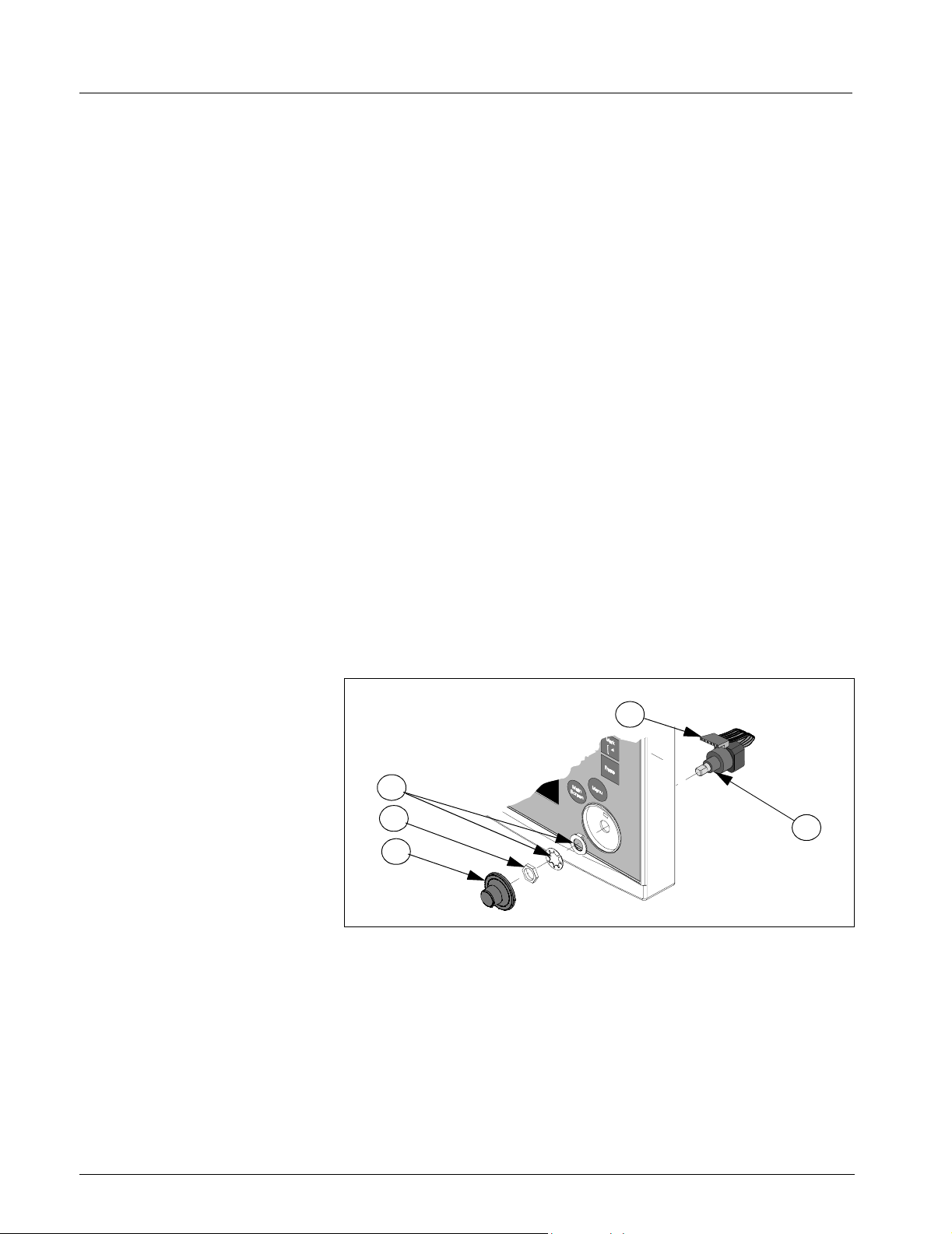
7.3 Optical Encoder
Subassembly
7.3.1 Removing Optical Encoder
Subassembly
6
3
2
1
Figure 3-11 Optical Encoder Subassembly.
Use the following procedure to remove / install the Optical Encoder
Subassembly.
1 Remove and save plastic frame and retainer plate from Front Bezel
Subassembly (see Section 7.1.1 on page 6).
2 Remove rotary knob (
Note: Rotary knob is press fitted onto metal shaft of Optical Encoder
Subassembly and must be removed very carefully to be reinstalled.
To remove knob pull it straight out and off of metal shaft. It may help
to wrap some removable tape around knob to get a better grip.
a
in Figure 3-9 on page 6 and in Figure 3-11.
5
Page 8 of 16 Siemens Medical Systems, EM-PCS, Danvers ASK-A898-03-7600
9kXL_12inDspl.sm_sup.fm/06-99/kaupp
Page 9

SC 9000XL Patient Monitors Service Manual Supplement Two - 12in (30.5cm) Display
3) Unplug optical encoder ribbon cable connector (h in Figure 3-9 and
Figure 3-11) from front bezel PC board.
s
securing
7.3.2 Installing Optical Encoder
Subassembly
4) Refer to Figure 3-9 on page 6 or Figure 3-11. Unscrew nut
optical encoder shaft in position in front bezel, and remove Optical
Encoder Subassembly
washer / positioning washer combination
1 Slide Optical Encoder Subassembly shaft through hole in front bezel,
positioned such that keyway on shaft is toward top of front panel.
2) Slide positioning washer removed in step 4 of Section 7.3.1 above
onto subassembly shaft so tab on hole in washer slides into keyway
on subassembly shaft and locking tab on washer is into hole in front
bezel above shaft.
Note: This assures that Optical Encoder Subassembly is positioned
so that its ribbon cable connector plugs properly into the front bezel
PC board and the subassembly doesn’t rotate in subsequent use.
3) Slide lockwasher and nut removed in step 4 of Section 7.3.1 above
onto subassembly shaft, and tighten to secure subassembly in bezel.
4) Plug optical encoder ribbon cable connector into front bezel PC board.
5) To reinstall knob, align and firmly press knob onto shaft.
6) Reinstall retainer plate and plastic frame in Front Bezel Subassembly
(see Section 7.1.2 on page 8), and reassemble Monitor. Refer to
Section 8 on page 11.
g
through back of bezel. Save nut, and lock
d
for use in reassembly.
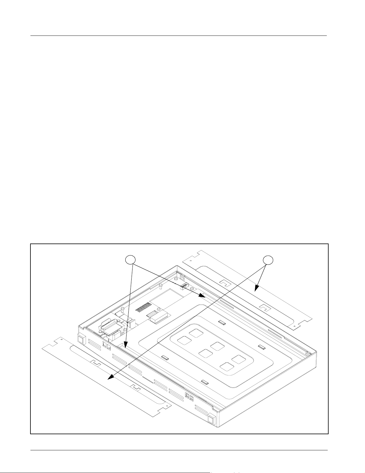
7.4 Front Bezel PC Board
7.4.1 Removing Front Bezel PCB In addition to removing the plastic frame and retainer plate w/ attached
backlight power supply PC board, it is necessary to remove the Optical
Encoder Subassembly, and Display Screen Subassembly, to access and
remove the Front Bezel PC Board.
1 Remove plastic frame and retainer plate (see Section 7.1.1 on page 6),
and Optical Encoder Subassembly (see Section 7.1.2 on page 8).
2 Unplug membrane switch ribbon cable connector (
on page 7) from front bezel PC board, and display screen flex cable
connector (
board.
3 Slide small screwdriver under tab near bottom on right hand side of
display subassembly, and carefully lift Display Screen Subassembly
k
(
in Figure 3-9) out of front bezel frame. Set subassembly aside on a
clean
Note: Be very careful that no dust or other foreign matter gets on the
front bezel lens or on the display screen surface.
4 Remove and save two screws (
that secure front bezel PC board interface connector to mounting tabs
on bezel frame.
5 Remove and save four remaining screws (
front bezel PC board to bezel frame.
6 Lift bottom right hand side of front bezel PC board off of bezel frame,
and slide board out from under interface connector mounting tabs to
remove board.
ASK-A898-03-7600 Siemens Medical Systems, EM-PCS Danvers Page 9 of 16
9kXL_12inDspl.sm_sup.fm/06-99/kaupp
d
in Figure 3-10a) from display screen subassembly PC
flat surface for use in reassembly.
s
in Figure 3-10 and Figure 3-10a)
j
a
in Figure 3-10a
in Figure 3-10a) securing
Page 10
Service Manual Supplement Two - 12in (30.5cm) Display SC 9000XL Patient Monitors
7.4.2 Installing Front Bezel PC
Board
1 With Optical Encoder and Display Screen Subassemblies removed,
and front bezel laying face down, bottom facing you, slide front bezel
PC board into position on mounting posts on bezel frame.
Note: Be sure that interface connector housing slides under bezel
frame connector mounting tabs.
2) Install screws removed in step step 4 of Section 7.4.2 above into
interface connector housing but do not tighten until step 4 below.
3) Install screws removed in step step 5 of Section 7.4.2 above, and
tighten to secure front bezel PC board to front bezel frame.
4) Tighten screws installed in step 2 to secure interface connector
housing to front bezel frame.
5) Locate Display Screen Subassembly in front bezel frame and press to
seat subassembly into position.
Note: Be very careful that no dust, finger prints, or other foreign
matter is on the front bezel lens or on the display screen surface.
6) Refer to Figure 3-10a on page 7. Plug display screen flex cable
connector
membrane switch ribbon cab le con nector
7) Reinstall Optical Encoder Subassembly (see Section 7.3.2 on page 9).
8) Reinstall retainer plate and plastic frame (see Section 7.1.2 on page 8).
d
into display screen subassembly PC board, and
a
into front bezel PC bo ard .
~
9) Reassemble monitor. Refer to Section 8 on page 11.
7
5
~
Figure 3-12Display Subassembly - Display Backlight Covers Removed
Page 10 of 16 Siemens Medical Systems, EM-PCS, Danvers ASK-A898-03-7600
9kXL_12inDspl.sm_sup.fm/06-99/kaupp
Page 11

SC 9000XL Patient Monitors Service Manual Supplement Two - 12in (30.5cm) Display
7.5 Replacing Backlights
The backlight fluorescent lamps are located inside the Display Screen
Subassembly (
the Display Screen Subassembly from the Front Bezel Subassembly to
replace backlights. Use the following procedure
1 Remove and save plastic frame and retainer plate from Front Bezel
Subassembly (see Section 7.1.1 on page 6).
2) Carefully peel back insulating tape (
enough to access top backlight cover (see
Figure 3-12).
3) Using very small Phillips-head screwdriver, remove and save four
screws (
in Figure 3-10a and in Figure 3-12) to Display Screen Subass embly.
4) Slide backlight covers toward center of Display Screen Subassembly
to release tabs, and lift covers off to access backlights (see
Figure 3-12 on page 10).
5) Observe positioning of backlights in channels (
install replacement backlights in identical manner.
6) Reinstall backlight covers, making sure that tabs lock into display sub-
assembly cover, and secure in place using screws removed in step 3.
7) Reinstall retainer plate and plastic frame (see Section 7.1.2 on page 8).
8) Reassemble monitor. Refer to Section 8 on page 11.
k
in Figure 3-9 on page 6). It is not necessary to remove
h
in Figure 3-10a on page 7) just
g
in Figure 3-10a and in
f
in Figure 3-10a on page 7) that secure backlight covers (g
g
in
j
in Figure 3-12) , and
7.6 Front Bezel/Lens
Subassembly
7.7 Front Bezel
Subassembly
8Closing Monitor
A replacement Front Bezel/Lens Subassembly ships with an installed lens,
mounting frame, Siemens logo and Model labels, and feet. The Language
Label Set (see
1 Open monitor (see Section 5 on page 3).
2 Remove LCD Display Subassembly, Optical Encoder Subassembly,
Front Bezel PC Board Subassembly, retainer plate, and plastic frame
from original front bezel subassembly and install in replacement bezel.
Refer to Sections 7.1, 7.3, and 7.4.
3 Install language label appropriate for customer site. Refer to old front
bezel as model, and to SC7000 and SC9000XL Patient Monitors
Service Manual for procedure.
4) Reassemble Monitor. Refer to Section 8.
A replacement Front Bezel Subassembly ships with Monitor Model label,
LCD Display Subassembly, Optical Encoder Subassembly, Front Bezel PC
Board Subassembly, Backlight Inverter PC Board, and retainer plate
installed. Only the language label (ordered separately from replacement
front bezel) needs to be installed on the bezel before closing the monitor.
Refer to section 4.2 in the Service Manual to install label, and then refer to
Section 8 in this supplement to close monitor.
1) With Rear Housing Subassembly backside down, position Front Bezel
Subassembly such that positioning guide on front bezel interfacing
connector slides into guide channel on rear housing connector, and
guides on sides and bottom of subassembly are partially inserted
along sides and botom of rear housing subassembly.
A
in Figure 3-9) must be ordered separately,
2) Assuring that interfacing connectors are properly aligned, carefully
press the two subassemblies together until two locking tabs on
ASK-A898-03-7600 Siemens Medical Systems, EM-PCS Danvers Page 11 of 16
9kXL_12inDspl.sm_sup.fm/06-99/kaupp
Page 12

Service Manual Supplement Two - 12in (30.5cm) Display SC 9000XL Patient Monitors
bottom of rear housing seat properly in front bezel and lock the
bottom of the two subassemblies together.
3) Reinstall locking plates at top of front bezel to pull bezel tightly against
rear housing.
4) Reinstall left and right side panels and ejector shaft cover. Refer to
Sections 5.1.2, 5.1.4, and 5.1.6 in the Service Manual.
5) Reinstall locking clips, if previously installed. See Figure 3-6a on pa ge 4.
6) Reconnect battery power and reinstall rear cover.
7) Functionally verify proper operation of the monitor before returning
the monitor to clinical servic e. Re fe r to Ch a p te r 4 , Fun c t io nal
Verification, in the SC 7000 and SC 9000XL Patient Monitors Service
Manual.
Page 12 of 16 Siemens Medical Systems, EM-PCS, Danvers ASK-A898-03-7600
9kXL_12inDspl.sm_sup.fm/06-99/kaupp
Page 13

SC 9000XL Patient Monitors Service Manual Supplement Two - 12in (30.5cm) Display
Appendix A
The following information is in addition to information already published in
Appendix A of the SC 7000 and SC 9000XL Patient Monitors Service
Manual (Art. No. 5949016E539U) and Supplement (Art. No.
and to the CD-ROM version (Art. No. 5944090E539U)
65
64
66
1 of 2
5952416E539U)
67
61
63
6 PL
Figure A-5 Front Bezel Subassembly Components
Table A-5 Front Bezel Subassembly - Replaceable Parts/Subassemblies
Item
No.
60 Optical Encoder SC Series 43 11 622 E533U
61 Rotary Knob SC Series 43 16 662 E533U
62 Front Bezel PC Board Subassembly 59 50 006 E539U
63 Foot .40 SQ X .25 THK (Pkg -12) 43 11 374 E533U
64
65 Front Bezel/Lens Subassembly (incl. installed item 63) 59 44 959 E539U
66
67 Backlight Inverter PC Board Subassembly 59 50 022 E539U
68 Plastic Mounting Frame 57 42 841 E539U
Language Label Kit
E/M SPR BACKLIGHT 12.1 TFT LCD
62
60
Description
69
Siemens Article
Number
59 53 877 E5 39U
59 54 347 E5 39U
68
69 Front Bezel Assembly (incl. all subassemblies in front bezel except language label) 59 44 934 E539U
ASK-A898-03-7600 Siemens Medical Systems, EM-PCS Danvers Page 13 of 16
9kXL_12inDspl.sm_sup.fm/06-99/kaupp
Page 14

70
Figure A-6 Rear Housing and Funnel (Exploded View)l
Table A-6 Rear Housing and Funnel
71
Item
No.
70 Rear Housing Subassembly (incl. Connector I/O PCB) 59 52 945 E539U
71 Funnel 57 33 139 E5 39U
Note: For all other replaceable components in the Rear Housing Subassembly, refer to Figures A-1 and A-3
in the SC 7000 and SC 9000XL Patient Monitors Service Manuals.
Description
Siemens Article
Number
Page 15

SC 9000XL Patient Monitors Service Manual Supplement Two - 12in (30.5cm) Display
If procedures in this Supplement are performed by other than Siemens service personnel, for more information
contact your local Siemens service representative. Technical support for Siemens service personnel is available
as follows:
In North and South America: In Europe, Asia, Africa, Australia, and New Zealand:
Siemens Medical Systems, Inc. Siemens-Elema AB
EM-PCS EM
Technical Support and Services Technical Support and Services
16 Electronics Avenue 171 95 Solna, Sweden
Danvers, MA 01923 USA
Tel: (978) 907-7500 Tel: Int+46-8-730-7641
FAX (978) 907-7546 FAX: Int+46-8-986 662
ASK-A898-03-7600 Siemens Medical Systems, EM-PCS Danvers Page 15 of 16
9kXL_12inDspl.sm_sup.fm/06-99/kaupp
Page 16

SC 7000 and SC 9000XL Patient Monitors - Service Manual Supplement Two
Order No. 59 53 620 E539U
©Siemens - Elema AB, 1999. Electromedical Systems Division. All rights reserved. No part of this publication may be
reproduced, stored in a retrieval system, or transmitted in any form or by any means, electronic, mechanical, photocopying,
recording, or otherwise, without the prior permission of the copyright owner in writing.
Subject to alterations without prior notice.
Issued by Siemens Medical Systems, EM-PCS, 16 Electronics Ave., Danvers, MA 02193, U.S.A.
ASK-A898-03-7600
E331.E539U.640.10.03.02
Printed in U.S.A.
Supplement 2, June, 1999
TU 0699 0.25
 Loading...