

Siemens SAK 51, SAK 52 Installation Instructions Manual
s
LCD Remote keypad
SAK 51 / 52
SLK 51/52 UK
A6E80113520
Installation instructions
Fig. 1
8AA12722 - E0 - 05/11/2003 - UK - A6E81272280
1. Product description
The SAK 51 and SAK 52 remote keypads are used to operate
and program the central control units. The SAK 52 also has a
speaker and microphone for audio verification.
2. Supply package
The SAK 51 and SAK 52 supply packages contain the
following,
- One SAK 51 or SAK 52 remote keypad.
- One SLK 51/52 language kit with:
- installation instructions,
- operating instructions,
- one plastic front.
3. Mounting instructions
The SAK 51 and SAK 52 are designed for mounting in dry
indoor rooms. They must not be exposed to dripping or
splashing water.
Avoid touching and spilling any dust on the contact of the
keyboard.
Fig. 2
r
Y
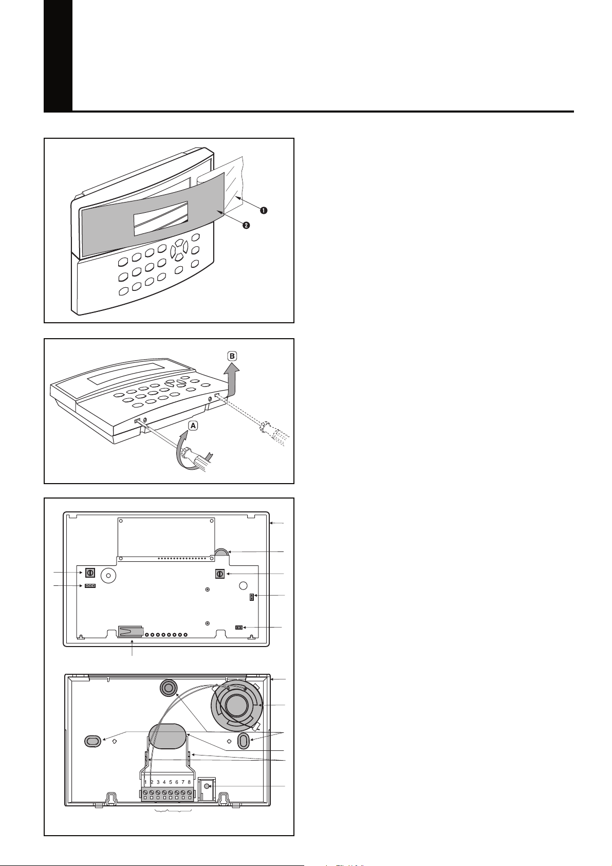
3.1 Secure plastic front (fig. 1)
1 - Peel back the backing foil Q half way.
2 - Place the plastic front W in the recess.
3 - Stick down the plastic front in the recess whilst peeling
away the remaining backing foil.
3.2 Open housing (fig. 2)
1 - Release both locking tabs (A) and remove top section (B).
3.3Product overview (fig. 3)
Q
W
e
E
R
T
U
- Q Mounting base,
- W Circuit board SMK 51,
- E Jumper for the microphone sensitivity,
- R Jumper for speaker volume,
- T Tamper contact,
- Y Jumper for the Buzzer
- U Cover of the Keypad,
- I Speaker
- O Mounting holes,
- P Cable inlet,
- { Cable clip,
- } Back tamper contact screw,
- q E-Bus connection,
- w Audio connection,
- e Potentiometer for LED display,
- r Potentiometer for buzzer volume.
Fig. 3
I
3.4 Fit housing (fig. 3)
O
P
{
}
q
w
1 - Pull the cable through the cable inlet P .
2 - Secure the mounting base O using two screws.
3 - Use the cable clip { .
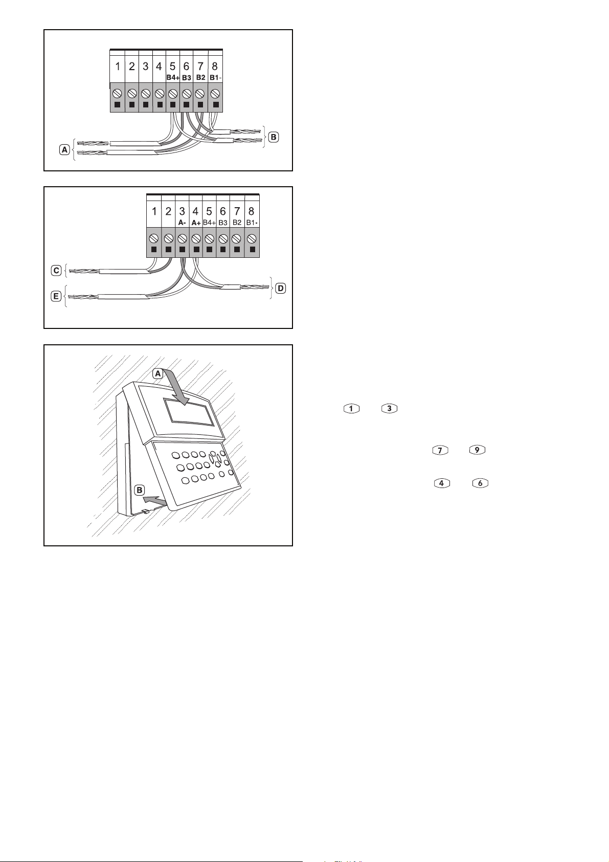
Fig. 4
Fig. 5
4. Wiring
4.1 E-Bus (fig. 4)
The E-Bus (B4+,B3,B2,B1-) must be connected to the
central control panel (A) and also to other accessories (B).
For additional information see the Control panel installation
manual
4.2 Audio for SAK 52 (fig. 5)
Connect terminals A- and A+ to the central control unit (E) (e.g.
WMA 11), and also to other accessories (D).
Connect terminals 1 and 2 to the speaker (C).
A twisted pair with a minimum diameter of 0.6 mm must be
used to avoid extraneous noise. The length of the audio link
to the central control unit must not exceed 200 m.
5. Close and seal the housing (fig. 6)
1 - Engage the cover in the top retainer (A).
2 - Close the cover (B).
6. Start-up
6.1 Microphone sensitivity
The sensitivity of the microphone can be set using the
connector (fig. 3 item E). Connector closed = max. sensitivity,
connector open = min. sensitivity.
6.2 Speaker volume
The volume of the speaker can be set using the connector
(fig. 3 item R). Connector closed = max. volume, connector
open = min. volume.
Fig. 6
6.3 Addressing
To enter an address in the remote keypad, simultaneously press
keys and and hold for approximately 5 sec.
6.4 Display address
To display the current address of the remote keypad,
simultaneously press keys and .
6.5 Test of displays
Simultaneously press keys and to activate all LEDs
and the buzzer.
7. Technical data
Supply (12 VDC) From the E-Bus
Power consumption min. 22,5 mA
Power consumption max. 105 mA
Operating temperature 0° C to +55° C
Housing ABS
Dimensions in mm H 110 x W 170 x D 32
Safety class IP 30
Environmental class II
Weight 250 g
The right to make technical changes to the described equipment without prior notice
is reserved - © 2002 -
 Loading...