

Siemens SA-3I, SA-11P Installation/wiring Instructions

INSINS
INSINS
INS
TT
TT
T
ALLAALLA
ALLAALLA
ALLA
TION/WIRING INSTION/WIRING INS
TION/WIRING INSTION/WIRING INS
TION/WIRING INS
TRTR
TRTR
TR
UCTIONSUCTIONS
UCTIONSUCTIONS
UCTIONS
MODELMODEL
MODELMODEL
MODEL
S SS S
S SS S
S S
AA
AA
A
-3I -3I
-3I -3I
-3I
AND SAND S
AND SAND S
AND S
AA
AA
A
-1-1
-1-1
-1
1P1P
1P1P
1P
AIR DUCT DETECTAIR DUCT DETECT
AIR DUCT DETECTAIR DUCT DETECT
AIR DUCT DETECT
OROR
OROR
OR
SS
SS
S
INTRODUCTION
Model SA-3I and SA-1 1P detectors from Siemens Industry , Inc. are self-contained air duct detectors designed for installation in heating, ventilating, and air conditioning duct systems. These
Detector Models SA-3I and SA-11P can use ionization or photoelectric smoke detectors to signal the presence of combustion products in a duct system. (Refer to TECHNICAL DA T A for information on compatible detectors.)
In addition to the self-contained detection features of the SA-3I and SA-11P, these air duct
detectors also can power and supervise the following configurations.
(1) two air duct detectors (Model AD-3I or AD-11P) mounted on the exterior of the duct and
employing sampling tubes to monitor the air in the duct, or
(2) two spot detectors (Model PE-11) mounted on the interior wall of the air duct, or
(3) one each of the detectors listed in (1) and (2) above.
TECHNICAL DA T A
Smoke Detector Compatibility: SA-3I - Use Model DI-B3 or DI-B3H only
SA-11P - Use Model PE-11
AD-3I (Satellite) - Use Model DI-B3 or DI-B3H only
AD-11P (Satellite) - Use Model PE-11
Operation Voltage and Current: 120 VAC (50/60 Hz), .32A max
Alarm Relay: DPDT contacts, rated at 125 VAC/24 VDC, 3A Resistive
Trouble Relay: SPDT contacts, rated at 125 VAC/24 VDC, 2A Resistive
Smoke Detector Sensitivity: Factory set for air duct application—See detector
nameplate label
Alarm Indicator: LED on smoke detector displays steady or flashing red
light through air duct cover
Temperature Range: 32
O
F (0OC) to 100O F (37.8OC) per UL 268/268A
Altitude Range: SA-3I, using DI-B3 - Altitude range is 0 to 4000 feet
above sea level
SA-3I, using DI-B3H - Altitude range is 3000 to 8000 feet
above sea level
SA-11P, using PE-11 - No altitude limitations; detectors
unaffected by altitude
Relative Humidity Range 0 to 93% (non-condensating) RH per UL 268/268A
Air Duct Velocity Range: SA-3I: 500 to 4000 ft/min
SA-11P: 300 to 4000 ft/min
Sampling Tube Pressure SA-3I: 0.017 to 1.07 inches of water
Differential Range: SA-1 1P: 0.006 to 1.07 inches of water
CAUTION: These air duct detectors are designed for detection of products of combus-
tion in a duct system. They are not to be used for open area protection.
P/N 315-096274-4
Siemens Industry, Inc.
Building Technologies Division
Florham Park, NJ
Siemens Building Technologies, Ltd.
Fire Safety & Security Products
2 Kenview Boulevard
Brampton, Ontario
L6T 5E4 Canada
2
OPERATION
When the SA-3I or SA-11P is in operation, a sample of air is drawn from the duct and passed
through the sampling chamber at low velocity by means of the inlet sampling tube. The air
sample passes through the smoke detector mounted in the duct housing and is exhausted back into the
duct via the outlet sampling tube.
Standby Indication
During normal operation the green Power LED on the power supply control board, located in the wiring
compartment of the SA-3I/-1 1P, is lit, indicating that AC power is being applied. The alarm and trouble
relays are in non-alarm and non-trouble states during standby operation.
Alarm Indication
Each smoke detector used with the SA-3I/-1 1P includes an LED for visual alarm indication. If the air
duct detector is not visible, a remote alarm lamp can be used for visual alarm indication. (See
Figure 6 for models.)
Alarm Operation
An alarm signal from the smoke detector within the SA-3I/-1 1P or from a satellite detector causes
the alarm relay in the SA-3I/-11P to energize.
The Model SA-3I/-1 1P can be wired for direct alarm relay control of normally energized and de-energized
devices. Refer to ELECTRICAL WIRING for details. When all products of combustion are cleared from
the duct system, the Model SA-3I/-1 1P can be reset by operating the RESET switch with the Reset key.
WARNING: Air duct detectors SA-3I/-11P cannot be used for releasing service.
Trouble Condition
A trouble condition in the SA-3I/-11P or in a satellite unit due to a loss of detector supervision causes
the trouble relay in the SA-3I/-1 1P to de-energize. Loss of AC power to the SA-3I/-11P results in the
green Power LED turning off and the trouble relay de-energizing.
MOUNTING THE AIR DUCT HOUSING
Location on Duct System
The air duct detector should be located in the main supply duct, downstream from the filters and
positioned so as to operate reliably in case of smoke in any part of the air stream. In instances where
the filters are capable of removing smoke, a detector should be installed both upstream and downstream from the filters.
The air duct detectors, because they use sampling tubes which monitor the full width of an air duct,
overcome the limitations of spot-type smoke and heat detectors in the duct. However, since stratification can occur in the air stream after a long duct run, it is desirable to locate the detector after bends or
inlets which create turbulence, and hence, a more homogeneous mixture of air. The detector should,
when possible, be located a minimum of six duct-widths downstream from the source of turbulence
(see Figure 1). A 12 inch by 12 inch access hole should be cut in the duct adjacent to the detector
to permit checking and cleaning the sampling tubes.
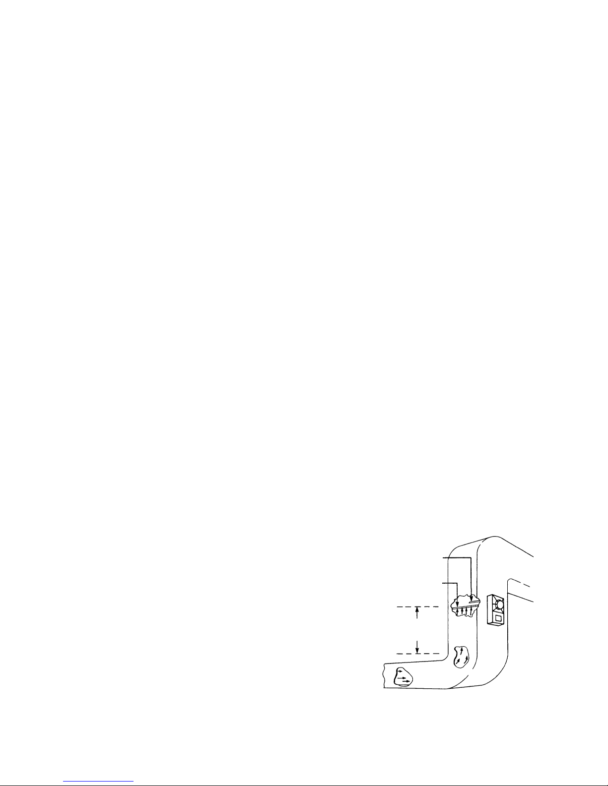
The air duct detector should be located in the air handling
system, as shown in Figure 2, and should be in conformance
with NFP A Pamphlet No. 90A, Air Conditioning and V enti-
lating Systems and with NFP A 72 National Fire Alarm Code .
(Both publications are available from the National Fire Protection Association, Batterymarch Park, Quincy, Massachusetts.) The detector on the return air side of the blower should
be located at a point prior to exhausting air from the building
or diluting return air with outside air. The detector on the supply air side of the blower should be downstream of the blower.
The detectors should be wired into the system so that they
automatically shut down the blowers and operate dampers
as required.
Mounting the Air Duct Housing (See Figure 3)
a. Affix the adhesive backed gaskets (Item 1) to the back of the detector housing (2) so that the larger
hole on the gasket lines up with the sampling tube hole on the sampling chamber and the
smaller hole with the housing mounting hole.
Figure 1
Typical Mounting of Duct
OUTLET
SAMPLING TUBE
INLET
SAMPLING TUBE
AT LEAST
SIX DUCT
WIDTHS
3
Figure 2
Recommended Locations in Duct Systems
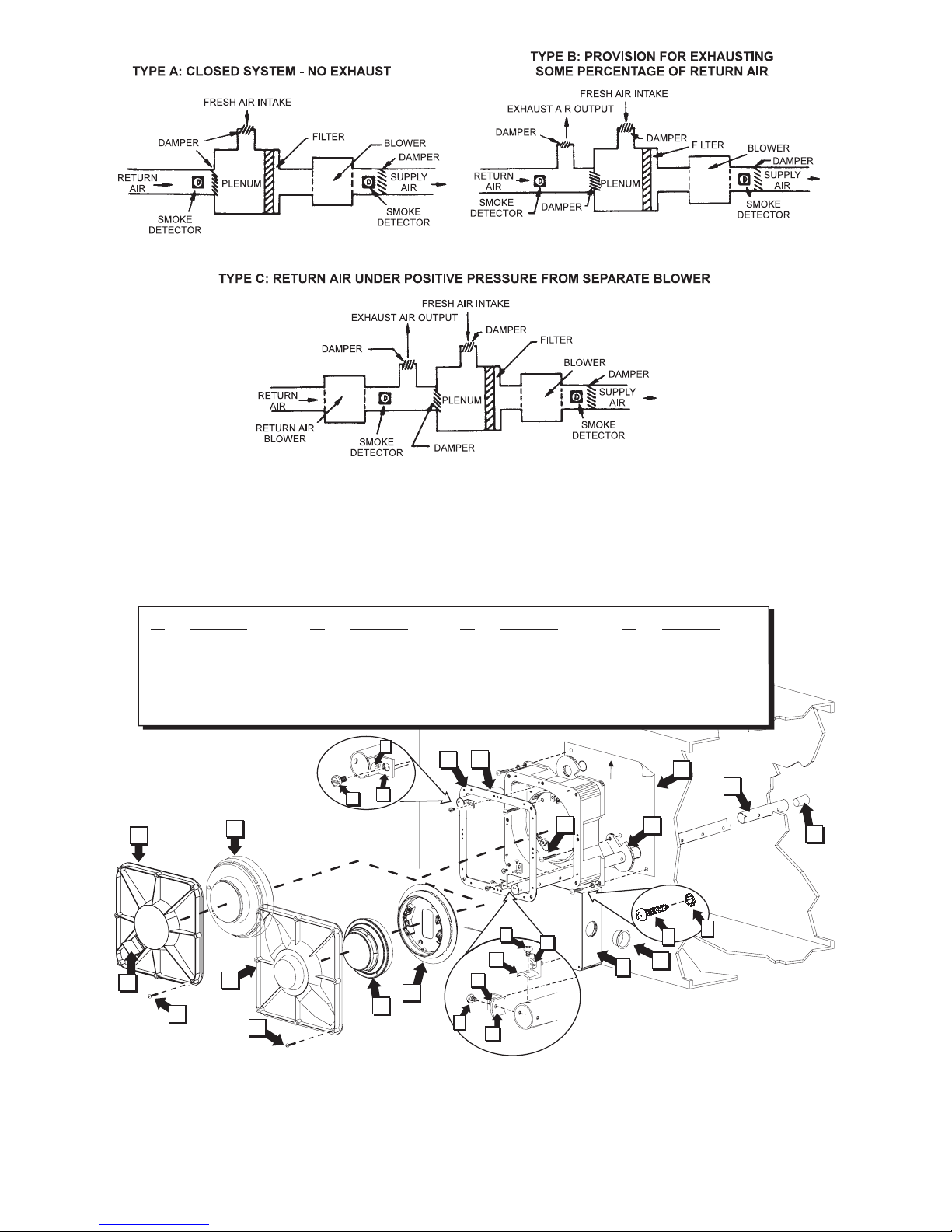
Figure 3
Exploded View
17
15
20
16
4
9
5
3
19
14
18
18
13
2
6
1
8
7
UP
11
12
10
11
11
12
12
10
10
21
ITEM
No.
ITEM
No.
ITEM
No.
ITEM
No.
1
2
3
4
5
7
8
9
10
11
13 19
14
20
15
21
16
17
COMPONENT
COMPONENT COMPONENT COMPONENT
(2) Sampling Tube Gasket
(1) Housing
(1) Inlet Sampling Tube
(1) Outlet Sampling Tube
(1) Template
(2) Screw, No. 10 - 1
(2) Lockwasher
(1) Rubber Stopper
(3) Bracket
(3) Screw,
3/16
(1) Plug
(1) Detector PE-11
(1) Ionization Detector Cover
(1) Detector DI-B3, DI-B3H
(1) Sensitivity Test Jack Lid
(1) Cover Gasket
(1) PE-11 Detector Cover
(1) DB-ADPT Base Adapter
12 18(3) Screw,
8/32
(8) Screw, No. 6
6 (2) Screw, No. 10 - 1
1/2
 Loading...