

Page 1
Release 1.0
Service Manual
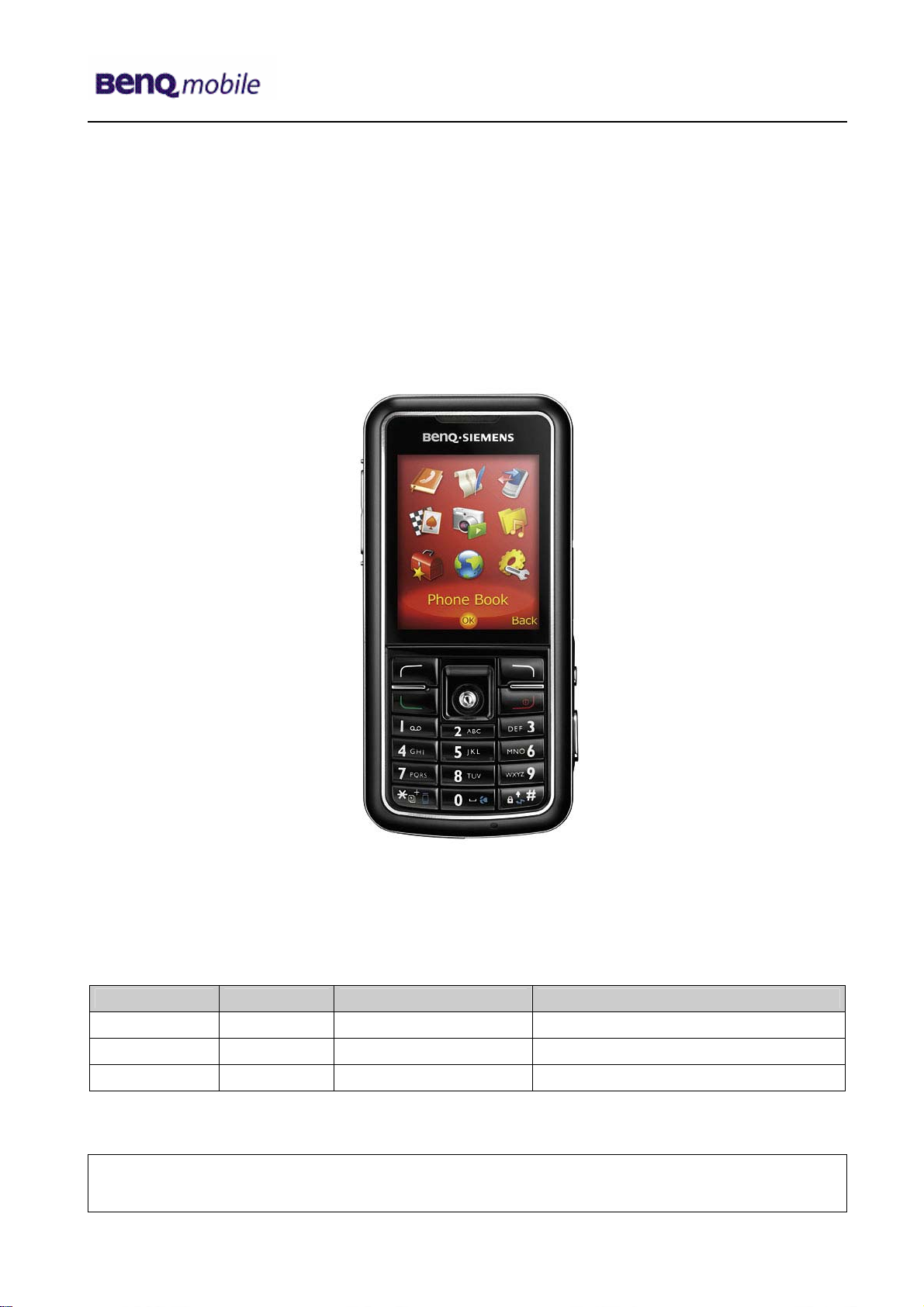
S88
Level 1-3
Release Date Department Notes to change
R 1.0 15.02.2006 BenQ Mobile CC S CES New document
Technical Documentation
TD_Repair_L2.5L_S88_R1.0.pdf Page 1 of 61
Company Confidential
2006©BenQ
02/2006
Page 2

Release 1.0
Table of Content
1 Key Feature................................................................................................................................3
2 Unit Description of S88.............................................................................................................4
3 Exploded View of S88 ...............................................................................................................5
4 Disassembly of S88...................................................................................................................6
5 Assembly of S88......................................................................................................................20
6 BenQ Service Equipment User Manual.................................................................................31
7 Setup of the Software..............................................................................................................32
8 Software basic settings ..........................................................................................................33
9 Software Download procedure...............................................................................................34
10 Download PPF (Handset configuration)................................................................................36
11 Backup and Restore of Wap and Network Setting...............................................................38
12 Backup and Restore of Media Center content......................................................................39
13 Unlock Tool..............................................................................................................................40
14 International Mobile Equipment Identity, IMEI......................................................................42
15 General Testing Information...................................................................................................43
16 Introduction of Service Repair Documentation Level 3 (basic) – S88.............................49
17 List of available Level 3 (basic) parts....................................................................................50
18 Hardware requirements ..........................................................................................................50
19 S88 Board Layout....................................................................................................................51
20 SIM Card Problems .................................................................................................................52
21 IO Connector Problems ..........................................................................................................53
22 Battery Connector Problems.................................................................................................. 54
23 RF Antenna Problems.............................................................................................................55
24 Micro SD Connector Problems...............................................................................................56
25 Camera Connector Problems.................................................................................................57
26 Display Problems ....................................................................................................................58
27 Charger Problems ...................................................................................................................59
28 Keypad Problems....................................................................................................................60
29 Flash light Problems...............................................................................................................61
Technical Documentation
TD_Repair_L2.5L_S88_R1.0.pdf Page 2 of 61
Company Confidential
2006©BenQ
02/2006
Page 3
Release 1.0
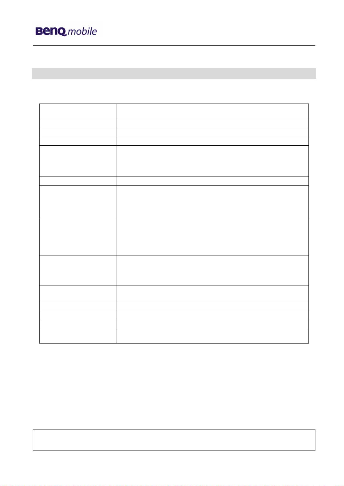
1 Key Feature
System
Battery
Stand – by Time
Talking Time
Memory
External Memory
Display
Keypad
Function key
Camera
Connectivity
FM Radio
Camcorder
MP3 – Player
• Tri-band handset (GSM900/DCS1800/PCS1900) or
(GSM850/DCS1800/PCS1900) with internal antenna
• Li – Ion 920mAh battery
• Up to 200 hours
• 130min~450min
• NOR flash: 128MB
• NAND flash: 256MB
• Pseudo SRAM: 64MB
• Mobile SDRAM: 128MB
• Micro SD/Transflash
• Display mode: Active Matrix, OLED
• Active area: 31.152mm x 38.94mm
• Pixel pitch: 0.177mm x 0.177mm
• Number of Colours: 260K
• 12 numerical key (including *,#)
• 5-way navigation key
• Soft keys: Left and Right
• Send key
• End/Power key
• Side keys:
o Volume keys
o Camera/Video mode switch button
o Camera shutter button
• 2.0 mega pixel; CMOS Auto Focus camera for image and
video recording
• USB 1.1; Bluetooth
• Embedded in Mobile Phone
• Support MPEG 4/ 3GP
• Support MP3/AAC
• Equalizer
Technical Documentation
TD_Repair_L2.5L_S88_R1.0.pdf Page 3 of 61
Company Confidential
2006©BenQ
02/2006
Page 4
Release 1.0
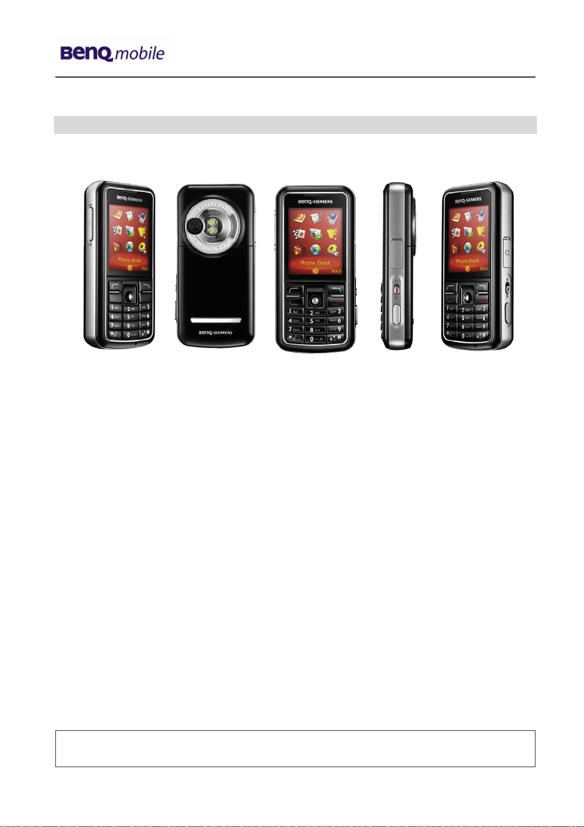
2 Unit Description of S88
Technical Documentation
TD_Repair_L2.5L_S88_R1.0.pdf Page 4 of 61
Company Confidential
2006©BenQ
02/2006
Page 5
Release 1.0
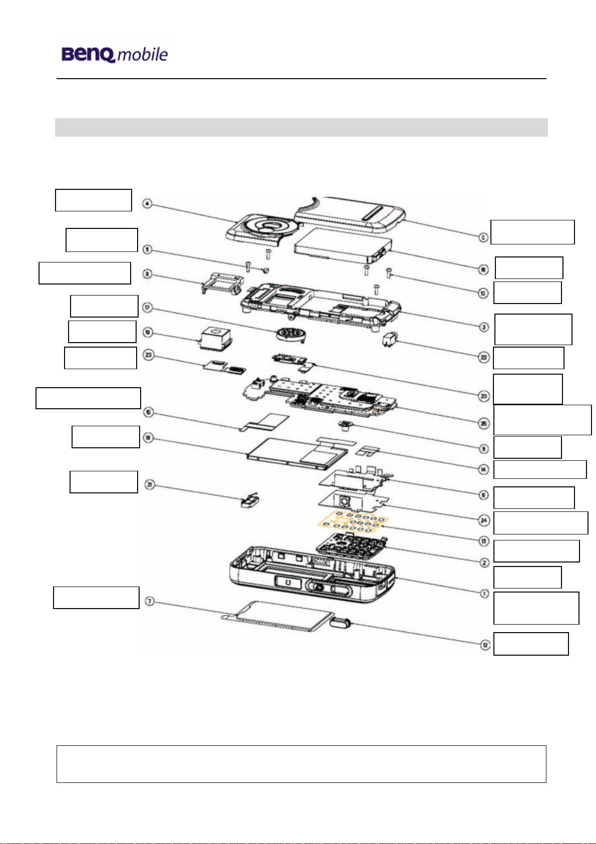
3 Exploded View of S88
Rear Cover
Side Screw
Battery Cover
Camera Frame
Ringer
Camera
Flex Cable
Adhesive Strip
Display
Earpiece
Battery
Screws
Lower Case
Vibramotor
Flash light
RF Control
Joystick
Keypad MMI
Flexible Keypad
Dome Keypad
Keypad
Display Cover
Technical Documentation
TD_Repair_L2.5L_S88_R1.0.pdf Page 5 of 61
Company Confidential
2006©BenQ
Upper Case
Shell
Key Shutter
02/2006
Page 6
Release 1.0
4 Disassembly of S88
All repairs as well as disassembling and assembling have to be carried out in an ESD
protected environment and with ESD protected equipment/tools. For all activities the
international ESD regulations have to be considered.
For more details please check information in c – market
https://market.benqmobile.com/SO/welcome.lookup.asp
There you can find the document “ESD Guideline”.
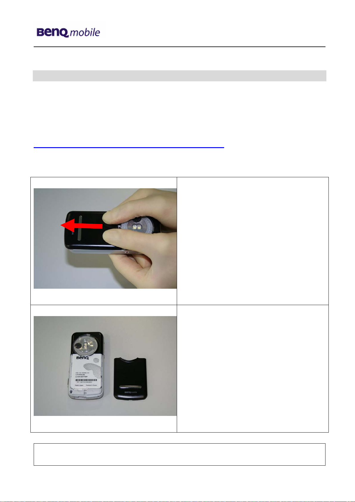
Step 1
Step 2
Remove Battery
Cover.
Technical Documentation
TD_Repair_L2.5L_S88_R1.0.pdf Page 6 of 61
Company Confidential
2006©BenQ
02/2006
Page 7
Release 1.0
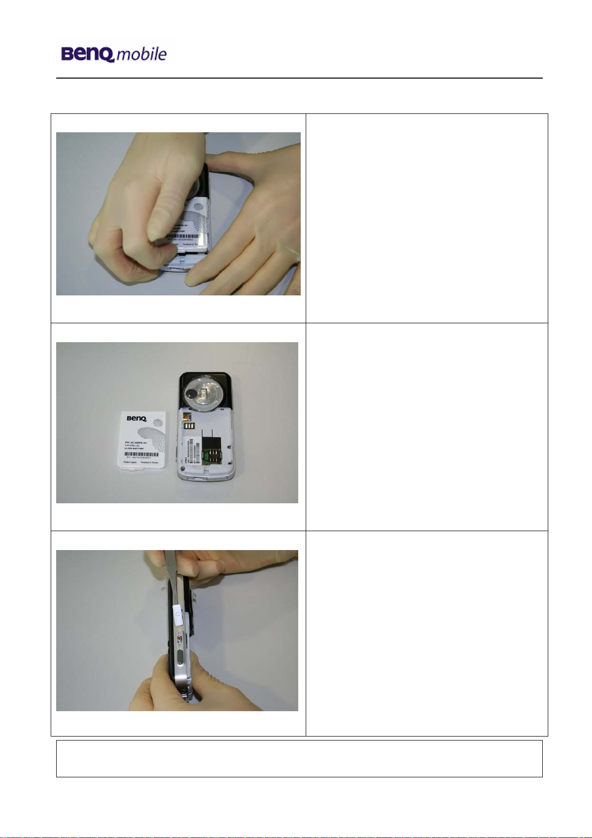
Step 3
Step 4
Remove Battery.
Step 5
Open Handset – Cover to remove Side
Screw. Use the Torque – Screwdriver T5.
Technical Documentation
TD_Repair_L2.5L_S88_R1.0.pdf Page 7 of 61
Company Confidential
2006©BenQ
02/2006
Page 8
Release 1.0
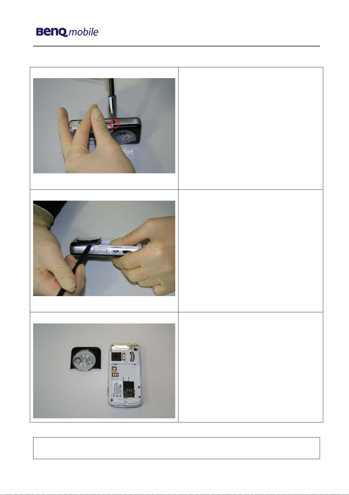
Step 6
Step 7
Remove Screw.
Remove Camera Cover by using Alternative
Opening Tool carefully.
Step 8
Technical Documentation
TD_Repair_L2.5L_S88_R1.0.pdf Page 8 of 61
Company Confidential
2006©BenQ
02/2006
Page 9
Release 1.0
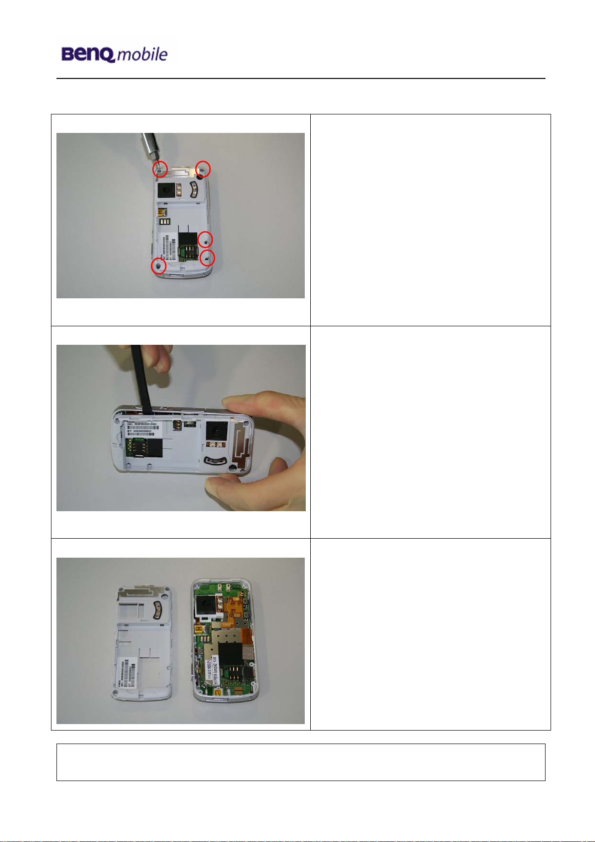
Step 9
Step 10
Remove screws with the Torque –
Screwdriver.
T5
Remove Lower Case Shell from Upper
Case Shell with Alternative Opening Tool.
Be very careful.
Step 11
Technical Documentation
TD_Repair_L2.5L_S88_R1.0.pdf Page 9 of 61
Company Confidential
2006©BenQ
02/2006
Page 10
Release 1.0
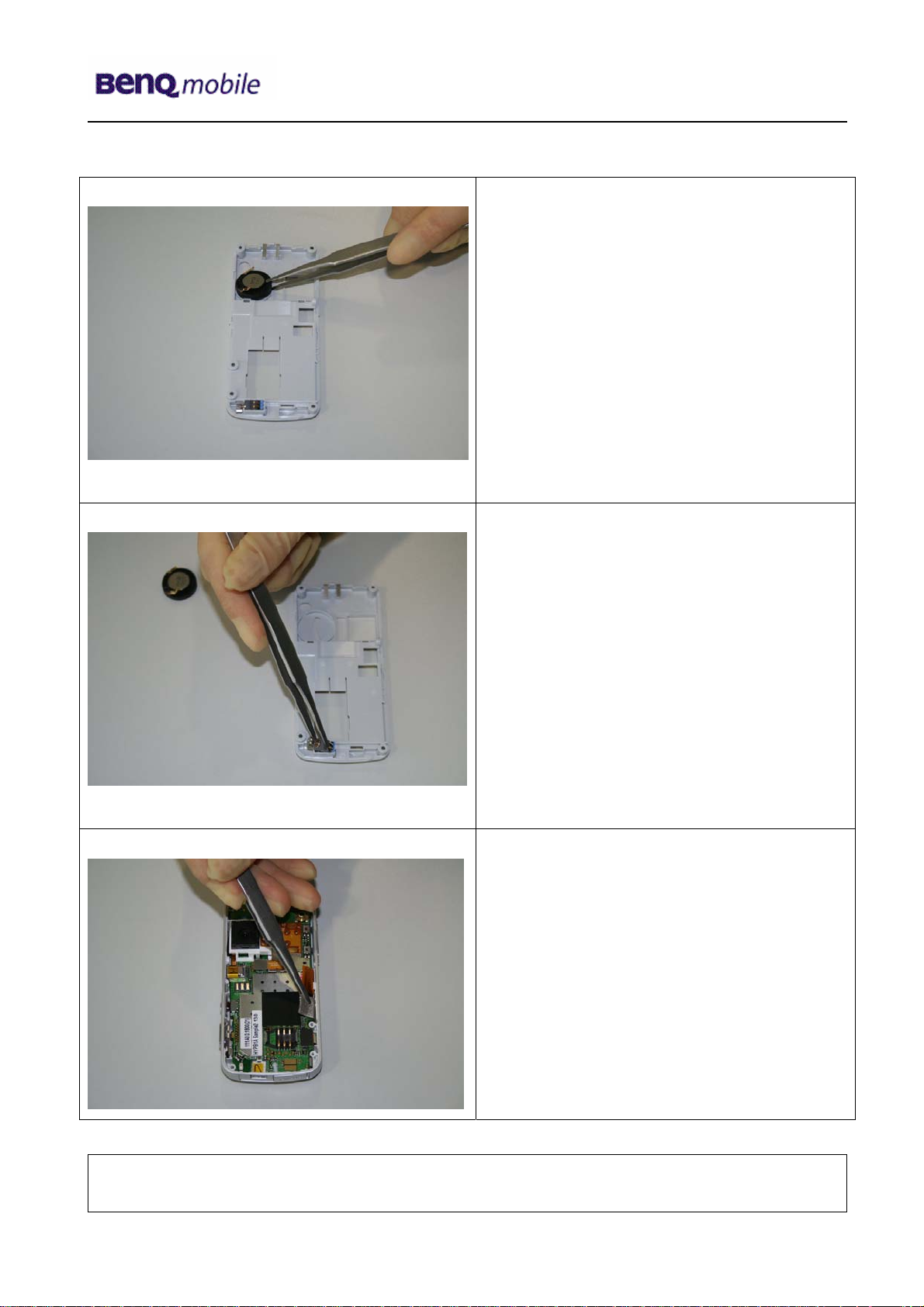
Step 12
Step 13
Remove Ringer by using Tweezers.
Remove Vibramotor by using Tweezers.
Step 14
Use Tweezers to disconnect the Flex Cable
from the RF Control Board sockets.
Technical Documentation
TD_Repair_L2.5L_S88_R1.0.pdf Page 10 of 61
Company Confidential
2006©BenQ
02/2006
Page 11
Release 1.0
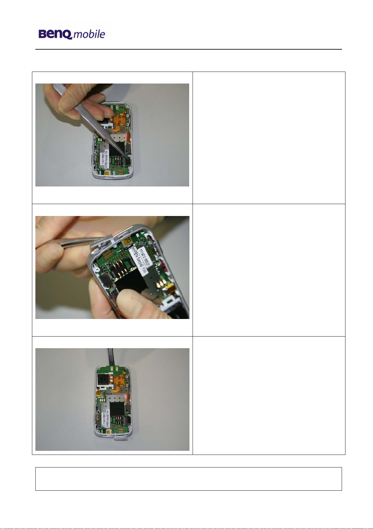
Step 15
Step 16
Pull the Memory Card Cover forward to
remove the RF Control Board.
Step 17
Remove RF Control Board from Lower
Case with Alternative Opening Tool
carefully.
Technical Documentation
TD_Repair_L2.5L_S88_R1.0.pdf Page 11 of 61
Company Confidential
2006©BenQ
02/2006
Page 12
Release 1.0
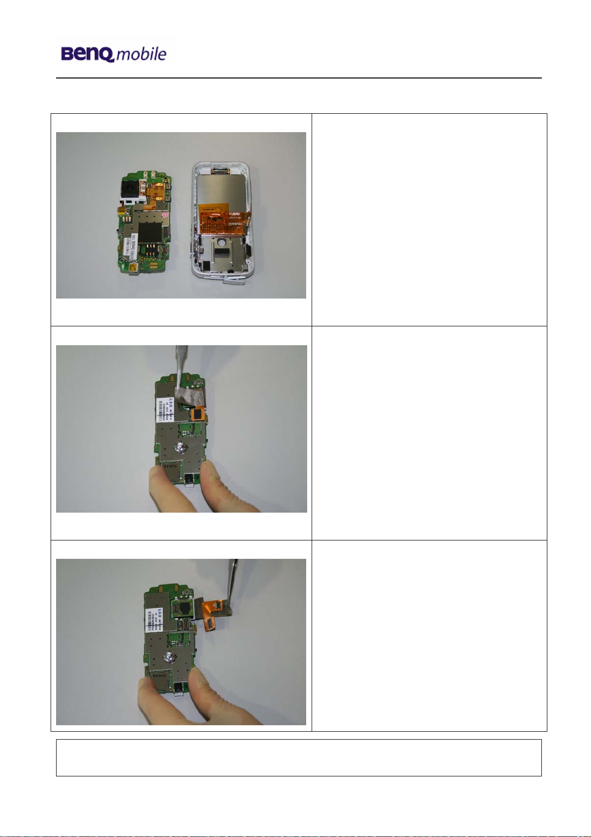
Step 18
Step 19
Disconnect the Adhesive Strip with Flex
Cable from the RF Control Board by using
Tweezers carefully.
Step 20
Technical Documentation
TD_Repair_L2.5L_S88_R1.0.pdf Page 12 of 61
Company Confidential
2006©BenQ
02/2006
Page 13
Release 1.0
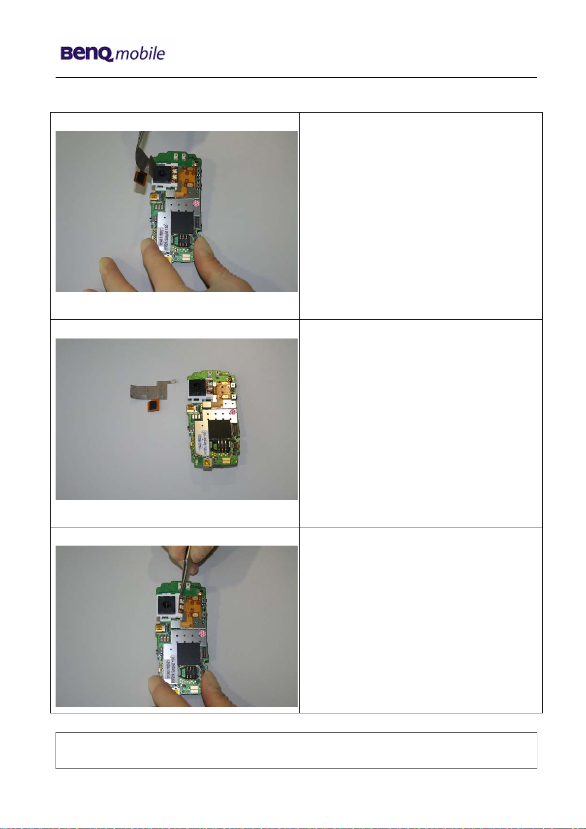
Step 21
Step 22
Step 23
Disconnect Flash light Flex Cable from
Camera Frame. Take care of the Flex
Cable!!!
Technical Documentation
TD_Repair_L2.5L_S88_R1.0.pdf Page 13 of 61
Company Confidential
2006©BenQ
02/2006
Page 14
Release 1.0
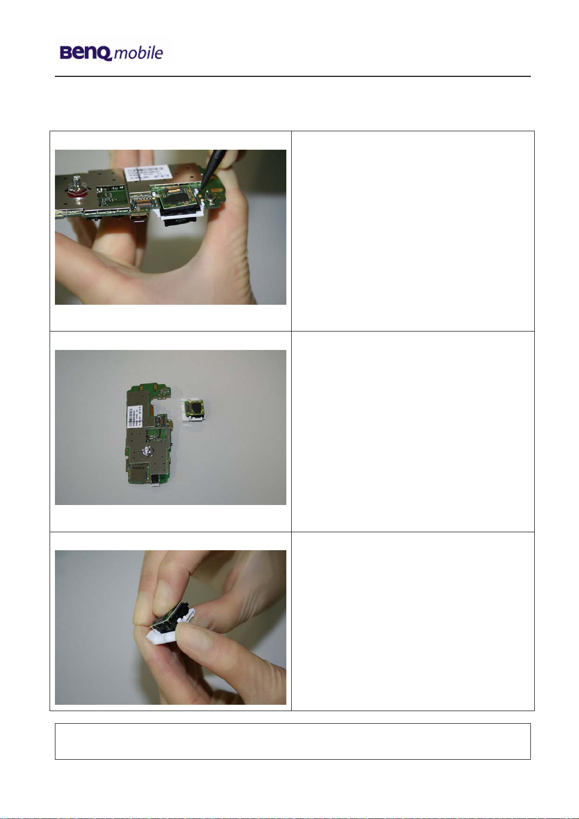
Step 24
Step 25
Remove Camera with Camera Frame by
pressing the hooks together.
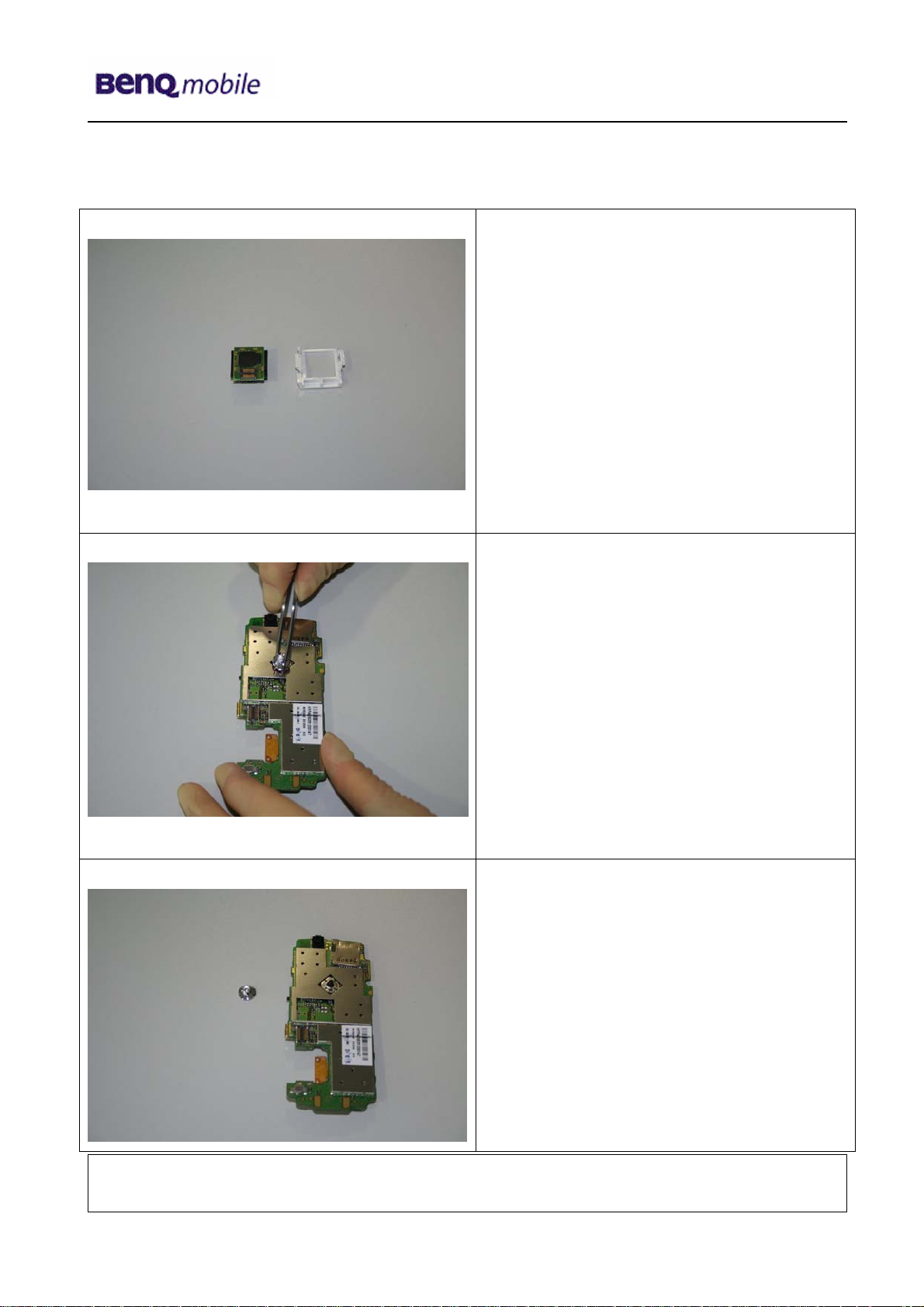
Step 26
Disassemble Camera Frame from Camera.
Technical Documentation
TD_Repair_L2.5L_S88_R1.0.pdf Page 14 of 61
Company Confidential
2006©BenQ
02/2006
Page 15
Release 1.0
Step 27
Step 28
Remove Joystick by using Tweezers.
Step 29
Technical Documentation
TD_Repair_L2.5L_S88_R1.0.pdf Page 15 of 61
Company Confidential
2006©BenQ
02/2006
Page 16
Release 1.0
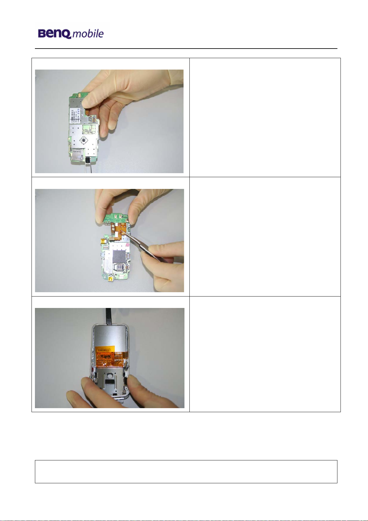
Step 30
Remove Microphone Shielding by using
Tweezers carefully.
Step 31
Step 32
Remove the Flash light Flex Cable from the
RF Control Board. Use Tweezers very
carefully!
Remove the Display by using the
Alternative Opening Tool.
Technical Documentation
TD_Repair_L2.5L_S88_R1.0.pdf Page 16 of 61
Company Confidential
2006©BenQ
02/2006
Page 17
Release 1.0
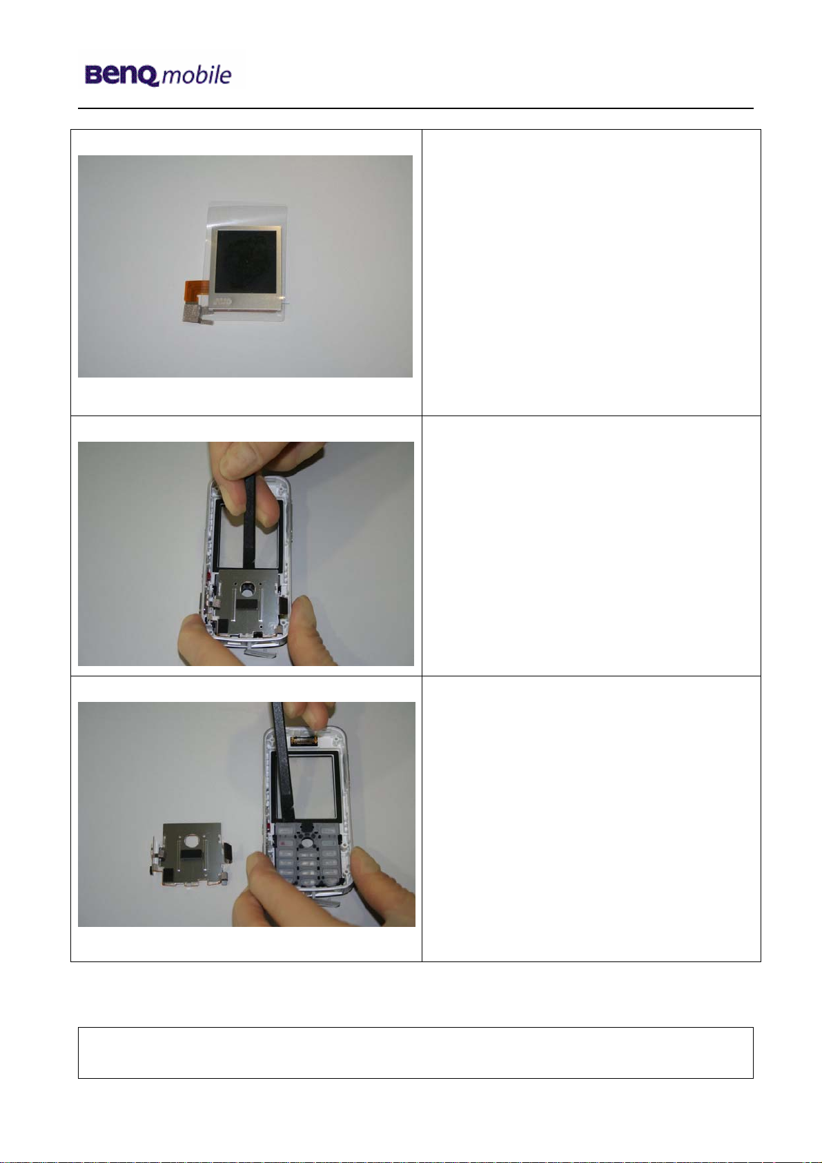
Step 30
To avoid scratches it is mandatory to place
a protection foil onto the Display!!!
Step 31
Step 32
Use Alternative Opening Tool to remove the
Keypad MMI.
Remove Keypad by using Alternative
Opening Tool.
Technical Documentation
TD_Repair_L2.5L_S88_R1.0.pdf Page 17 of 61
Company Confidential
2006©BenQ
02/2006
Page 18
Release 1.0
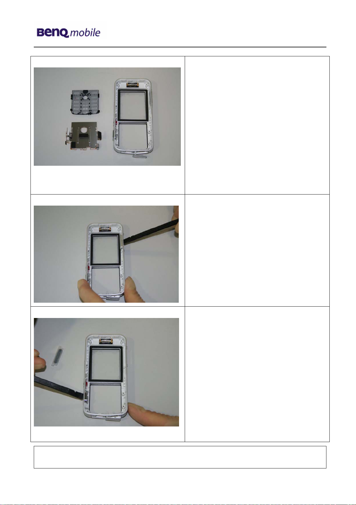
Step 33
Step 34
Step 35
Remove the Side Keys by pushing them
outside the frames.
Technical Documentation
TD_Repair_L2.5L_S88_R1.0.pdf Page 18 of 61
Company Confidential
2006©BenQ
02/2006
Page 19
Release 1.0
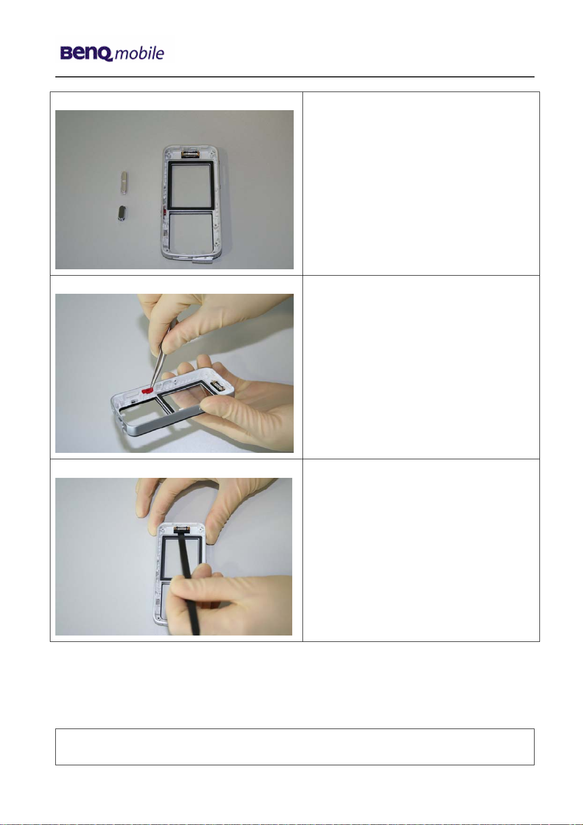
Step 36
Step 37
Step 38
Remove Camera – Video - Key by using
Tweezers.
Remove the Earpiece with the Alternative
Opening Tool.
Technical Documentation
TD_Repair_L2.5L_S88_R1.0.pdf Page 19 of 61
Company Confidential
2006©BenQ
02/2006
Page 20

Release 1.0
y
yp
Overview Upper Parts Overview Lower Parts
Adhasive
Strip with
Flex Cable
Upper
Case Shell
PCB Display
Keypad
Lower
Case Shell
Battery Cover
Rear Cover
Flex Cable
Earpiece
Side Ke
Joystick
Camera Frame
s
and Camera
5 Assembly of S88
Step 1
Ke
ad MMI
Screws
Vibramotor
Ringer
Battery
Assemble Earpiece by using Tweezers.
Step 2
Assemble Camera – Video – Key by using
Tweezers.
Technical Documentation
TD_Repair_L2.5L_S88_R1.0.pdf Page 20 of 61
Company Confidential
2006©BenQ
02/2006
Page 21

Release 1.0
Step 3
Step 4
Assemble Side Keys by using Tweezers.
Step 5
Assemble Keypad.
Technical Documentation
TD_Repair_L2.5L_S88_R1.0.pdf Page 21 of 61
Company Confidential
2006©BenQ
02/2006
Page 22

Release 1.0
Step 6
Step 7
Assemble Keypad MMI.
Remove the Display Foil from the Display.
Step 8
Assemble the Display in the given frame.
Technical Documentation
TD_Repair_L2.5L_S88_R1.0.pdf Page 22 of 61
Company Confidential
2006©BenQ
02/2006
Page 23

Release 1.0
Step 9
Step 10
Use Tweezers to assemble the
Microphone Shielding.
Assemble Joystick.
Step 11
Connect the Flash light Flex Cable with
the RF Control Board. Take care of the
Flex Cable!
Technical Documentation
TD_Repair_L2.5L_S88_R1.0.pdf Page 23 of 61
Company Confidential
2006©BenQ
02/2006
Page 24

Release 1.0
Step 12
Step 13
Assemble the Camera into the Camera
Frame.
Fit the Assembled Camera into the cut
out of the RF Control Board.
Step 14
Clip the Flash lights onto the Camera
Frame.
Technical Documentation
TD_Repair_L2.5L_S88_R1.0.pdf Page 24 of 61
Company Confidential
2006©BenQ
02/2006
Page 25

Release 1.0
Step 15
Fix the Adhesive Strip onto the
Camera Frame.
Step 16
Step 17
Technical Documentation
Turn the RF Control Board and fix the
end of the Adhesive Strip on the
shielding plate.
02/2006
TD_Repair_L2.5L_S88_R1.0.pdf Page 25 of 61
Company Confidential
2006©BenQ
Page 26

Release 1.0
Step 15
Step 16
Fix the RF Control Board into the Upper
Case Shell.
Step 14
Connect the Flex Cable with the RF
Control Board socket.
Technical Documentation
TD_Repair_L2.5L_S88_R1.0.pdf Page 26 of 61
Company Confidential
2006©BenQ
02/2006
Page 27

Release 1.0
Step 15
Connect the Flex Cable with the RF
Control Board socket.
Step 16
Step 17
Assemble the Ringer in the given frame of
the Lower Case Shell.
Assemble the Vibramotor in the given
frame of the Lower Case Shell.
Technical Documentation
TD_Repair_L2.5L_S88_R1.0.pdf Page 27 of 61
Company Confidential
2006©BenQ
02/2006
Page 28

Release 1.0
Step 18
Assemble Upper Case Shell with Lower
Case Shell.
Step 19
Step 20
Place screws with the Torque –
Screwdriver. T5.
Technical Documentation
TD_Repair_L2.5L_S88_R1.0.pdf Page 28 of 61
Company Confidential
2006©BenQ
02/2006
Page 29

Release 1.0
Step 21
Step 22
Assemble Rear Cover.
Assemble Battery.
Step 23
Place side screw. T5
Technical Documentation
TD_Repair_L2.5L_S88_R1.0.pdf Page 29 of 61
Company Confidential
2006©BenQ
02/2006
Page 30

Release 1.0
Step 24
Assemble Battery Cover.
Technical Documentation
TD_Repair_L2.5L_S88_R1.0.pdf Page 30 of 61
Company Confidential
2006©BenQ
02/2006
Page 31

Release 1.0
6 BenQ Service Equipment User Manual
Introduction
Every LSO repairing BenQ handset must ensure that the quality standards are observed.
BenQ has developed an automatic testing system that will perform all necessary
measurements. This testing system is known as:
BenQ Mobile Service Equipment
• For disassembling / assembling
Torque – Screwdriver
Part Number: F 30032 – P 228 – A1
Opening tool
(Case opening without destroying)
Part Number: F 30032 – P 38 – A1
Alternative Opening tool
Part Number: F30032 – P583 – A1
Tweezers
• For testing
All mobile phones have to be tested with the GRT – Software. The service partner is
responsible to ensure that all required hardware is available.
For additional Software and Hardware options as well as the supported GRT equipment,
please check the GRT User manual.
Technical Documentation
TD_Repair_L2.5L_S88_R1.0.pdf Page 31 of 61
Company Confidential
2006©BenQ
02/2006
Page 32

Release 1.0
7 Setup of the Software
Download of the required software:
Download the driver, the XCSD software mobile software (core-software and language files) from
the Technical Support Page:
https://market.benqmobile.com/so/welcome.lookup.asp
Installation of USB – Serial converter boot cable:
Start the “DataCableDrvInstaller.exe” file and follow the instructions of the installer.
Plug in the Data cable and follow the installation instructions to complete the process.
Check the Comport number of the data cable in the device manager.
(XCSD tool supports only Comport 1 to 10)
Technical Documentation
TD_Repair_L2.5L_S88_R1.0.pdf Page 32 of 61
Company Confidential
2006©BenQ
02/2006
Page 33

Release 1.0
Installation of XCSD tool:
Start “setup.exe” file and follow the instructions.
The installer creates a shortcut in the start menu bar. Start – Programs – XCSDTool_L1 - BenQS
8 Software basic settings
Start the software (BenQS.exe). The XCSD tool will be shown on the screen
Select Model:
Technical Documentation
TD_Repair_L2.5L_S88_R1.0.pdf Page 33 of 61
Company Confidential
2006©BenQ
02/2006
Page 34

Release 1.0
Select Com port (Setting – Com port):
9 Software Download procedure
Select Download Option (View – Download):
Technical Documentation
TD_Repair_L2.5L_S88_R1.0.pdf Page 34 of 61
Company Confidential
2006©BenQ
02/2006
Page 35

Release 1.0
Select Program Code (example: E22 1 11710.mot) and
Language Pack (example E22 L 11711.mot)
Status bar colour scheme:
yellow waiting for update
blue update in progress
red error occurred
black Comport not available
green Update successful
Connect mobile phone with data cable. Phone must be switched off. Click on “Start” button
and press the power on button on the handset to start the download. During download
process status bar shows the state of the process of P = Program code, L = Language file
and S = Set default (if activated). After successful SW download, the status bar of the used
Com port is changed to green.
Erase of customer data:
Select the “Power-off set default” option to erase all customer data of the phone during the
download process.
Click the “Set E2p” to erase the customer data without software update.
SW files naming rules:
Program Code E22111710
Language Pack E22L11711
E22 Project name
117 Program Code
L Language Pack
117 Version 1.17
10/11 Program Code ID
Technical Documentation
02/2006
TD_Repair_L2.5L_S88_R1.0.pdf Page 35 of 61
Company Confidential
2006©BenQ
Page 36

Release 1.0
10 Download PPF (Handset configuration)
Select write PPF option (View – Write PPF):
Select Database File (example: E22111710.bin) and
PPF File (example benq_m315_twn.ppf)
Connect mobile phone with data cable. Phone must be switched on. Click to “Write PPF”
button to start the process.
Don’t activate
Technical Documentation
TD_Repair_L2.5L_S88_R1.0.pdf Page 36 of 61
Company Confidential
2006©BenQ
02/2006
Page 37

Release 1.0
Confirmation about successful write of PPF appears after process is completed.
Technical Documentation
TD_Repair_L2.5L_S88_R1.0.pdf Page 37 of 61
Company Confidential
2006©BenQ
02/2006
Page 38

Release 1.0
11 Backup and Restore of Wap and Network Setting
Select Back and Restore of Wap and Network Settings option
(View – Wap/Network Bkp/Restore):
Select Database File (example: E22111710.bin) and
Setting File (create new txt file and rename it to ntk file for settings backup)
Connect mobile phone with data cable. Phone must be switched off.
Click to “Backup” button to start the transfer the settings into the selected file.
Click to “Restore” button to start the transfer from selected file into handset.
Technical Documentation
TD_Repair_L2.5L_S88_R1.0.pdf Page 38 of 61
Company Confidential
2006©BenQ
02/2006
Page 39

Release 1.0
12 Backup and Restore of Media Center content
Select Back and Restore of Media center (View – Media center Bkp/Restore):
Select Media File (create new txt file and rename it to mmd file)
Connect mobile phone with data cable. Phone must be switched on.
Click to “Backup” button to start the transfer the settings into the selected file.
Click to “Restore” button to start the transfer from selected file into handset.
Technical Documentation
TD_Repair_L2.5L_S88_R1.0.pdf Page 39 of 61
Company Confidential
2006©BenQ
02/2006
Page 40

Release 1.0
13 Unlock Tool
Select Unlock tool function (View – Unlock Tool):
Select Database File (example: E22111710.bin)
Technical Documentation
TD_Repair_L2.5L_S88_R1.0.pdf Page 40 of 61
Company Confidential
2006©BenQ
02/2006
Page 41

Release 1.0
Click to “Show PW” button to get the codes.
Unlock the codes in the mobile phone menu.
Click to “Hide PW” button to hide the codes.
Technical Documentation
02/2006
TD_Repair_L2.5L_S88_R1.0.pdf Page 41 of 61
Company Confidential
2006©BenQ
Page 42

Release 1.0
14 International Mobile Equipment Identity, IMEI
The mobile equipment is uniquely identified by the International Mobile Equipment Identity,
IMEI, which consists of 15 digits. Type approval granted to a type of mobile is allocated 6
digits. The final assembly code is used to identify the final assembly plant and is assigned
with 2 digits. 6 digits have been allocated for the equipment serial number for manufacturer
and the last digit is spare.
S88 series IMEI label is accessible by removing the battery.
Re – use of IMEI label is possible by using a hair – dryer to remove the IMEI label.
Date code is shown on IMEI label: Detailed description on how to read date code is given in
Annex 2.
To display the IMEI number, exit code and SW/HW version, key: * # 300 #
Code *#301# activates self diagnosis.
Technical Documentation
TD_Repair_L2.5L_S88_R1.0.pdf Page 42 of 61
Company Confidential
2006©BenQ
02/2006
Page 43

Release 1.0
15 General Testing Information
General Information
The technical instruction for testing GSM mobile phones is to ensure the best repair quality.
Validity
This procedure is to apply for all from Siemens AG authorized level 2 up to 2.5e workshops.
Procedure
All following checks and measurements have to be carried out in an ESD protected
environment and with ESD protected equipment/tools. For all activities the international
ESD regulations have to be considered.
Get delivery:
¾ Ensure that every required information like fault description, customer data a.s.o. is
available.
¾ Ensure that the packing of the defective items is according to packing requirements.
¾ Ensure that there is a description available, how to unpack the defective items and
what to do with them.
Enter data into your database:
(Depends on your application system)
¾ Ensure that every data, which is required for the IRIS-Reporting is available in your
database.
¾ Ensure that there is a description available for the employees how to enter the data.
Technical Documentation
TD_Repair_L2.5L_S88_R1.0.pdf Page 43 of 61
Company Confidential
2006©BenQ
02/2006
Page 44

Release 1.0
Incoming check and check after assembling:
!! Verify the customers fault description!!
¾ After a successful verification pass the defective item to the responsible
troubleshooting group.
¾ If the fault description can not be verified, perform additional tests to save time and to
improve repair quality.
- Switch on the device and enter PIN code if necessary unblock phone.
- Check the
- Check the display for error in
function of all keys including side keys.
line and row, and for illumination.
- Check the ringer/loudspeaker acoustics by individual validation.
- Perform a GSM Test as described on page 36.
Check the storage capability:
¾ Check internal resistance and capacity of the battery.
¾ Check battery charging capability of the mobile phone.
¾ Check charging capability of the power supply.
¾ Check current consumption of the mobile phone in different mode.
Visual inspection:
¾ Check the entire board for liquid damages.
¾ Check the entire board for electrical damages.
¾ Check the housing of the mobile phone for damages.
SW update:
¾ Carry out a software update and data reset according to the master tables and
operator/customer requirements.
Repairs:
The disassembling as well as the assembling of a mobile phone has to be
carried out by considering the rules mentioned in the dedicated manuals. If
special equipment is required the service partner has to use it and to ensure the
correct function of the tools.
If components and especially soldered components have to be replaced all rules
mentioned in dedicated manuals or additional information e.g. service
information have to be considered
Technical Documentation
TD_Repair_L2.5L_S88_R1.0.pdf Page 44 of 61
Company Confidential
2006©BenQ
02/2006
Page 45

Release 1.0
GSM Test:
With the availability of the GRT Test /Alignment software, this tool has to be used to perform
the outgoing test!
>Connect the mobile/board via internal antenna (antenna coupler) and external antenna
(car cradle/universal antenna clip) to a GSM tester
>Use a Test SIM
For Triple Band phones use a separate test case, if the test software allows only one
handover.
Skip the GSM Band test cases if not performed by the mobile phone
Example: 1. Test file Band 1 = GSM900 / Band 2 = GSM1800
2. Test file Band 1 = GSM1900
Internal Antenna
Test case Parameter Measurements Limits
1 Location Update • GSM Band 1
• BS Power = -55 dBm
• middle BCCH
2 Call from BS • low TCH
• highest PCL
• BS Power = -75 dBm
• middle BCCH
3 TX GSM Band 1 • low TCH
• highest PCL
• BS Power = -75 dBm
• middle BCCH
4 Handover to GSM Band 2
Including Handover
Check
5 TX GSM Band 2 • low TCH
6 Call release from BS
• highest PCL0
• BS Power = -75 dBm
• middle BCCH
• Display check • individual
check
• Ringer/Loudspeaker
check
• Frequency Error
• Phase Error RMS
• Phase Error Peak
• Average Power
• Power Time Template
• Frequency Error
• Phase Error RMS
• Phase Error Peak
• Average Power
• Power Time Template
• individual
check
• GSM Spec.
• GSM Spec.
Technical Documentation
02/2006
TD_Repair_L2.5L_S88_R1.0.pdf Page 45 of 61
Company Confidential
2006©BenQ
Page 46

Release 1.0
External Antenna
7 Call from MS • GSM900
• high TCH
• second highest PCL
• BS Power = -75 dBm
• middle BCCH
8 TX GSM Band 1 • high TCH
• second highest PCL
• BS Power = -75 dBm
• middle BCCH
9 RX GSM Band 1 • high TCH
• BS Power = -102 dBm
• 50 Frames
• middle BCCH
10 Handover to GSM Band 2
Including Handover
Check
11 TX GSM Band 2 • high TCH
12 RX GSM Band2 • high TCH
13 Call release from MS
• second highest PCL
• BS Power = -75 dBm
• middle BCCH
• BS Power = -102 dBm
• 50 Frames
• middle BCCH
• Keyboard check • individual
check
• Frequency Error
• Phase Error RMS
• Phase Error Peak
• Average Power
• Power Time Template
• RX Level
• RX Qual
• BER Class Ib
• BER Class II
• BER Erased Frames
• Frequency Error
• Phase Error RMS
• Phase Error Peak
• Average Power
• Power Time Template
• RX Level
• RX Qual
• BER Class Ib
• BER Class II
• BER Erased Frames
• GSM Spec.
• GSM Spec.
• GSM Spec.
• GSM Spec.
Final Inspection:
The final inspection contains:
1) A 100% network test (location update, and set up call).
2) Refer to point 3.3.
3) A random sample checks of:
- Data reset (if required)
- Optical appearance
- complete function
4) Check if PIN-Code is activated (delete the PIN-Code if necessary).
Basis is the international standard of DIN ISO 2859.
Use Normal Sample Plan Level II and the Quality Border 0,4 for LSO.
Remark: All sample checks must be documented.
Technical Documentation
TD_Repair_L2.5L_S88_R1.0.pdf Page 46 of 61
Company Confidential
2006©BenQ
02/2006
Page 47

Release 1.0
Annex 1
Test SIM Card
There are two different “Test SIM Cards” in use:
1) Test SIM Card from the company “ORGA”
Pin 1 number: 0000
PUK 1 : 12345678
Pin 2 number: 0000
PUK 2 : 23456789
2) Test SIM Card from the company “T-D1”
Pin 1 number: 1234
PUK : 76543210
Pin 2 number: 5678
PUK 2 : 98765432
Technical Documentation
TD_Repair_L2.5L_S88_R1.0.pdf Page 47 of 61
Company Confidential
2006©BenQ
02/2006
Page 48

Release 1.0
Annex 2
Device Date Code overview
GSN rule:
(ex: GS11500001TG0)
GS 1 9 5 00001 TG0
Big class Date Month Year S/N Factory
Based on the definition above, GSC55... below means 2005/05/12.
Technical Documentation
TD_Repair_L2.5L_S88_R1.0.pdf Page 48 of 61
Company Confidential
2006©BenQ
02/2006
Page 49

Release 1.0
16 Introduction of Service Repair Documentation
Level 3 (basic) – S88
16.1 Purpose
This part of Service Repair Documentation is intended to carry out repairs on BenQ Mobile repair
level 3basic (only for workshops without level 3 equipment (special agreement required).
The described failures shall be repaired in BenQ authorized local workshops only.
The level 3basic partners are obliged to send exchanged boards (SWAP) to the next higher Service
Repair Partner.
All repairs have to be carried out in an ESD protected environment and with ESD protected
equipment/tools. For all activities the international ESD regulations have to be considered.
Assembling/disassembling has to be done according to the latest S88 Level 1-3 repair
documentation.
The Service Partner has to ensure that every repaired mobile Phone is checked according to the
latest released General Test Instruction document (both documents are available in the Technical
Support section of the C-market).
Check at least weekly C-market for updates and consider all S88 related Customer Care Information
The part number for the S88 is S88 where the last for letters specify the housing and
software variant.
Scrap Handling: All Scrap information given in this manual are related to the
SCRAP-Rules and instructions.
Attention: Consider the new "LEAD-FREE" soldering rules (available in the communication
market), avoid excessive heat.
16.2 Scope
This document is the reference document for all BenQ mobile authorised Service Partners which are
released to repair BenQ mobile phones up to level 2.5 light.
16.3 Terms and Abbreviations
Technical Documentation
TD_Repair_L2.5L_S88_R1.0.pdf Page 49 of 61
Company Confidential
2006©BenQ
02/2006
Page 50

Release 1.0
17 List of available Level 3 (basic) parts
Product Order Number Description CM
S88 L50634-Z97-C553 CONN DC PWR PA05302-QNJ
S88 L50634-Z97-C633 CONN AXK7L20227
S88 L50634-Z97-C634 CONN AXK7L30227
S88 L50634-Z97-C635 CONN AXK734245
S88 L50634-Z97-C636 CONN BF1-0115
S88 L50634-Z97-C554 CONN ANT RF05301-PG
S88 L50634-Z97-C556 CONN BAT3PD2.5AB303Y-C0G1
S88 L50634-Z97-C558 CONN I/O 10P P0.5
S88 L50634-Z97-C637 CONN SIM BM05306-D18
S88 L50634-Z97-C638 CONN MEMORY 11TFC-001
S88 L50615-Z77-C287 SWI RF ANTENNA MS-147
18 Hardware requirements
(According to General soldering information V1.3 - check C-market for updates)
Jigs, Tools and working materials for all described repairs:
hot air blower
soldering gun
tweezers
flux
solder
Technical Documentation
02/2006
TD_Repair_L2.5L_S88_R1.0.pdf Page 50 of 61
Company Confidential
2006©BenQ
Page 51

r
r
19 S88 Board Layout
Upper board side
T – Flash
Socket
Microphone
Lower board side
DC Jack
Release 1.0
Backup Battery
Battery Connecto
Camera Connector
10 Pin I/O
Flash
Connector
SIM Connector
Keypad Connector
Technical Documentation
TD_Repair_L2.5L_S88_R1.0.pdf Page 51 of 61
Display
Connecto
02/2006
Company Confidential
2006©BenQ
Page 52

Release 1.0
y
y
r
y
y
20 SIM Card Problems
Okay
Okay
Not
oka
Okay
Back to customer
without repair
Not
oka
Caused by customer
SCRAP - has to be send
separately to WSC
Exchange the
damaged Filter
- check for twisted or
bent contacts
- check for dry joints
Continue with
higher repair level
Fault Symptoms
Customer: GRT:
Handset does not accept SIM card Support in February 2006
SIM Card Problems
Watch for oxidation and
damaged pads of the
SIM Card reader
Check the status of the
EMI Filter visually
Not
oka
Check the status of the
SIM Card reader visually
Okay
Exchange
SIM Card reade
Not
oka
Use the resistor test
function of a multimeter
to check connection
between spring
contacts and soldering
contacts.
The value must be ~0
Connector SIM Card Reader
Use soldering iron to remove defective component. Avoid excessive heat! Watch surrounding
components! Resolder new component afterwards.
E-commerce order number: L50634-Z97-C637
E-commerce order name:
Soldering temperature: ~ 360°C TIP Temp.
CONN SIM BM05306-D18
Technical Documentation
02/2006
TD_Repair_L2.5L_S88_R1.0.pdf Page 52 of 61
Company Confidential
2006©BenQ
Page 53

Release 1.0
y
y
y
21 IO Connector Problems
Fault Symptoms
Customer: GRT:
Problems with external loudspeaker or microphone when using a
car kit
Problems with accessories connected at the IO connector
IO connector Problems
Watch for oxidation and
damaged pads of the
IO connector
Not
oka
Okay
Not
oka
Not
okay
Check the dust inside
the IO connector
Okay
Check the status of the
IO connector visually
Exchange
IO connector
Connector IO Jack
Use soldering iron to remove defective component. Avoid excessive heat! Watch surrounding
components! Resolder new component afterwards.
E-commerce order number: L50634-Z97-C558
E-commerce order name: CONN I/O 10P P0.5
Soldering temperature: ~ 360°C TIP Temp.
IRIS Diagnose Code: 47300 Interface/Data Interface/Mechanical Damage
Not
oka
Use the resistor test
function of a multimeter
to check connection
between spring
contacts and soldering
contacts.
The value must be ~0
Okay
4B100 Interface/Headset Connector/Mechanical Damage
Support in February 2006
Back to customer
without repair
Caused by customer
SCRAP - has to be send
separately to WSC
Clean IO connector
- check for twisted or
bent contacts
- check for dry joints
Continue with
higher repair level
Technical Documentation
02/2006
TD_Repair_L2.5L_S88_R1.0.pdf Page 53 of 61
Company Confidential
2006©BenQ
Page 54

Release 1.0
y
y
y
y
22 Battery Connector Problems
Okay
Okay
Back to customer
without repair
Not
oka
Okay
Caused by customer
SCRAP - has to be send
separately to WSC
- check for twisted or
bent contacts
- check for dry joints
Continue with
higher repair level
Fault Symptoms
Customer: GRT:
Mobile does not switch on No connection to GRT
Battery connector problems
Watch for oxidation and
damaged pads of the
battery connector
Not
oka
Check the status of the
battery connector
visuall
Exchange
battery
connector
Not
oka
Use the resistor test
function of a multimeter
to check connection
between spring
contacts and soldering
contacts. The value
must be ~ 0.
Connector BATTERY
Use hot air blower to remove defective component. Avoid excessive heat! Watch surrounding
components! Resolder new component afterwards.
E-commerce order number: L50634-Z97-C556
E-Commerce name: CONN BAT3PD2.5AB303Y-C0G1
Soldering temperature: 240 - 255°C
IRIS Diagnose Code: 13000 Battery/Mechanical Damage
Technical Documentation
02/2006
TD_Repair_L2.5L_S88_R1.0.pdf Page 54 of 61
Company Confidential
2006©BenQ
Page 55

Release 1.0
y
r
y
y
23 RF Antenna Problems
Okay
Okay
Okay
Not
oka
Okay
Back to customer
without repair
Not
okay
Caused by customer
SCRAP - has to be send
separately to WSC
Clean RF
connector
- check for twisted or
bent contacts
- check for dry joints
Continue with
higher repair level
02/2006
Fault Symptoms
Customer: GRT:
Network search Failure by TX/RX measurements
No location update possible No location update possible
RF connector Problems
Watch for oxidation and
damaged pads of the
RF connector
Check the dust inside
the RF connector
Not
oka
Check the status of the
RF connector visually
Exchange
RF connecto
Not
oka
Use the resistor test
function of a multimeter
to check connection
between input and
output contacts.
The value must be ~0
Connector RF
Use hot air blower to remove defective component. Avoid excessive heat! Watch surrounding components!
Resolder new component afterwards.
E-commerce order number:
E-commerce name: CONN ANT RF05301-PG
E-commerce order number:
E-commerce name: SWI RF ANTENNA MS-147
Soldering temperature: 240 - 255°C
IRIS Diagnose Code:
81100 Radio / No Contact / Int. Antenna 81200 Radio / No Contact / Ext. Antenna
82100 Radio / Low Receiving Signal / Int. Antenna 82200 Radio / Low Receiving Signal / Ext. Antenna
83100 Radio / Dropped Calls / Int. Antenna 83200 Radio / Dropped Calls / Ext. Antenna
84100 Radios / Call Setup / Int. Antenna 84200 Radio / Call Setup / Ext. Antenna
Technical Documentation
L50634-Z97-C554
L50615-Z77-C287
TD_Repair_L2.5L_S88_R1.0.pdf Page 55 of 61
Company Confidential
2006©BenQ
Page 56

Release 1.0
y
y
y
24 Micro SD Connector Problems
not
okay
okay
Back to customer
without repair
caused by customer
SCRAP - has to be send
separately to WSC
- check for twisted or
bent contacts
- check for dry joints
Continue with
higher repair level
Fault Symptoms
Customer: GRT:
MMC malfunction Tbd.
Micro SD Connector Problems
Watch for oxidation and
damaged pads of the
Micro SD connector
okay
Exchange
Micro SD
connector
not
oka
not
oka
Check the status of the
Micro SD connector
visuall
okay
Use the resistor test
function of a multimeter
to check connection
between spring
contacts and soldering
contacts.
The value must be ~0
Connector MMC
Use soldering iron to remove defective component. Avoid excessive heat! Watch surrounding
components! Resolder new component afterwards.
E-commerce order number: L50634-Z97-C638
E-commerce order name:
CONN MEMORY 11TFC-001
Soldering temperature: ~ 360°C TIP Temp.
IRIS Diagnose Code: 4E000 Interfaces/ Memory Card Rerader
Technical Documentation
11/2005
TD_Repair_L1-L3_S88_R1.0.pdf Page 56 of 61
Company Confidential
2005©BenQ
Page 57

Release 1.0
y
y
y
25 Camera Connector Problems
not
oka
okay
Back to customer
without repair
caused by customer
SCRAP - has to be send
separately to WSC
- check for twisted or
bent contacts
- check for dry joints
Continue with
higher repair level
Fault Symptoms
Customer: GRT:
Camera malfunction Tbd.
Camera connector Problems
Watch for oxidation and
damaged pads of the
camera connector
okay
not
okay
Check the status of the
camera connector
visuall
Exchange
camera
connector
not
oka
Use the resistor test
function of a multimeter
to check connection
between spring
contacts and soldering
contacts.
The value must be ~0
Connector CAMERA
Use hot air blower to remove defective component. Avoid excessive heat! Watch surrounding
components! Resolder new component afterwards.
E-commerce order number: L50634-Z97-C634
E-commerce order name: CONN AXK7L30227
Soldering temperature: ~ 360°C TIP Temp.
IRIS Diagnose Code: BA000 Accessories / Camera
Technical Documentation
11/2005
TD_Repair_L1-L3_S88_R1.0.pdf Page 57 of 61
Company Confidential
2005©BenQ
Page 58

Release 1.0
y
y
y
y
26 Display Problems
not
oka
okay
Back to customer
without repair
caused by customer
SCRAP - has to be send
separately to WSC
- check for twisted or
bent contacts
- check for dry joints
Continue with
higher repair level
Fault Symptoms
Customer: GRT:
Display problems Current measured failed
Display Problems
Watch for oxidation and
damaged pads of the
Display connector
okay
not
oka
Check the status of the
Display connector
visuall
Exchange
display
connector
not
oka
Use the resistor test
function of a multimeter
to check connection
between spring
contacts and soldering
contacts.
The value must be ~0
Connector DISPLAY
Use hot air blower to remove defective component. Avoid excessive heat! Watch surrounding
components! Resolder new component afterwards.
E-commerce order number: L50634-Z97-C635
E-commerce order name:
CONN AXK734245
Soldering temperature: ~ 360°C TIP Temp.
IRIS Diagnose Code: 21000 Display / Performance
22000 Display / Background Illumination
Technical Documentation
11/2005
TD_Repair_L1-L3_S88_R1.0.pdf Page 58 of 61
Company Confidential
2005©BenQ
Page 59

Release 1.0
27 Charger Problems
Fault Symptoms
Customer: GRT:
Charger Problems Tbd.
Charger problems
Watch for oxidation and
damaged pads of the
connector
Okay
Not
okay
Check the status of the
connector visually
Okay
Not
Exchange
okay
connector
Use the resistor test
function of a multimeter
to check connection
between spring
contacts and soldering
contacts. The value
must be ~ 0.
E-commerce order number: L50634-Z97-C553
E-commerce order name: CONN DC PWR PA05302-QNJ
IRIS Diagnose Code: 46100 Interface/Charging Connector/Mechanical Damage
Back to customer
without repair
Not
okay
Okay
Caused by customer
SCRAP - has to be send
separately to WSC
- check for twisted or
bent contacts
- check for dry joints
Continue with
higher repair level
Technical Documentation
11/2005
TD_Repair_L1-L3_S88_R1.0.pdf Page 59 of 61
Company Confidential
2005©BenQ
Page 60

Release 1.0
y
y
y
y
28 Keypad Problems
not
oka
okay
Back to customer
without repair
caused by customer
SCRAP - has to be send
separately to WSC
- check for twisted or
bent contacts
- check for dry joints
Continue with
higher repair level
Fault Symptoms
Customer: GRT:
Keypad problems Current measured failed
Keypad Problems
Watch for oxidation and
damaged pads of the
Keypad connector
okay
not
oka
Check the status of the
Keypad connector
visuall
Exchange
Keypad
connector
not
oka
Use the resistor test
function of a multimeter
to check connection
between spring
contacts and soldering
contacts.
The value must be ~0
E-commerce order number: L50634-Z97-C633
E-commerce order name: CONN AXK7L20227
Soldering temperature: ~ 360°C TIP Temp.
IRIS Diagnose Code: 21000 Display / Performance
22000 Display / Background Illumination
Technical Documentation
11/2005
TD_Repair_L1-L3_S88_R1.0.pdf Page 60 of 61
Company Confidential
2005©BenQ
Page 61

Release 1.0
y
y
y
y
29 Flash light Problems
not
oka
okay
Back to customer
without repair
caused by customer
SCRAP - has to be send
separately to WSC
- check for twisted or
bent contacts
- check for dry joints
Continue with
higher repair level
Fault Symptoms
Customer: GRT:
Flash light problems Current measured failed
Flash Light Problems
Watch for oxidation and
damaged pads of the
Flash light connector
okay
not
oka
Check the status of the
Flash light connector
visuall
Exchange
Flash light
connector
not
oka
Use the resistor test
function of a multimeter
to check connection
between spring
contacts and soldering
contacts.
The value must be ~0
E-commerce order number: L50634-Z97-C636
E-commerce order name:
CONN BF1-0115
Soldering temperature: ~ 360°C TIP Temp.
IRIS Diagnose Code: 21000 Display / Performance
22000 Display / Background Illumination
Technical Documentation
11/2005
TD_Repair_L1-L3_S88_R1.0.pdf Page 61 of 61
Company Confidential
2005©BenQ
 Loading...