

Page 1
Local Service Organization Service Manual
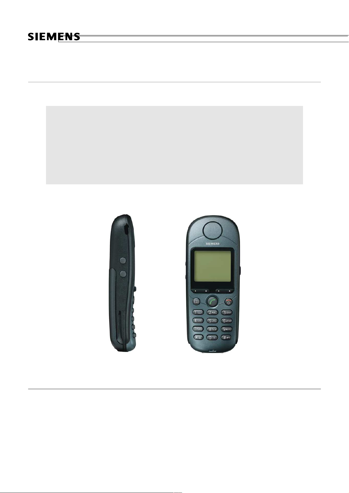
S 3 5 i
S 3 5 i
S I E M E N S I N F O R M AT I O N A N D C O M M U N I C AT I O N M O B I L E
V1.0
Page 2
Table of Contents
C H A P T E R 1
Level 2 Service Guide
Introduction 1
S35i Series Technical Information 2
Accessories 4
General Information 5
S35i Series Exploded Diagram 7
Mechanical Concept 8
Hardware Concept – Block diagram 9
Hardware Description 10
Power Supply Concept 11
Over voltage Condition 11
Battery – Charging 12
Short Circuit Protection 12
Charging 13
S35i Mobile Phone Spare Parts Level 2 15
Disassembling/Assembling the S35i 16
Mobile Software Programming 22
Mobile Software Updating 22
Language Groups 23
Customer Specific Initialization 25
International Mobile Equipment Identity 25
Phone Unblocking 26
Disclaimer 28
Level 2 Service Guide
Introduction
The document is intended to help you carry out repair up to Level 2 on the S35i series mobile
phone.
The repair for international version and Asian variants are identical unless otherwise noted,
therefore the description herein is confined to S35i only.
The S35i electrical design is similar to the C35 mobile phone – they use same PCB and
electronics component for majority of the circuit. For testing and the accessories for the S35i
please refer to the C35 service manual.
All repairs have to be carried out in an environment set up
according to ESD regulations defined in international standards.
V1.0 ii
Chapter
1
¸
Page 3

ESD procedure is available from your Service Manager. Ask for ASC/T001/98
V1.0 iii
Page 4

Page 5

S35 i Technical Information
System GSM Phase 2/Phase 2+, Dual Band
EGSM 900, Class 4(2 Watt)
GSM 1800, Class 1(1 Watt)
Operating Voltage 3.6V
Size(LxWxH) 118 x 46 x 21 mm(without antenna)
Volume 89cm3 including battery (approx)
Weight 105g including battery (approx)
Battery(Standard) Li-Ion, 600mAH (Standard)
Standby time
1
60-220 hours (standard battery)
Talk time
1
100-360 minutes (standard battery)
Charging Time 2 hours
SIM support Plug in card 1.8 V or 3V
Antenna Integrated
Speech codec Triple rate Enhance Full Rate
Full Rate
Half Rate
Display 101 x 80 pixel graphical display with up to 6 lines
12 x 12 font size for Chinese
Keypad 12 numeric keys(10 numeric, #, *)
4 function keys(Send, End-ON/OFF, Menu, Phonebook)
2 multifunctional softkeys
Key Sound Click/DTMF/None
Key Lock Activation and Deactivation by #-key or
Automatic.
1
Actual time dependent on the network.
V1.0
1
Page 6

Dialing 10 redial numbers,
Last 10 incoming with date stamp
Last 10 outgoing calls
Last 10 missed calls with date stamp
Ringer On/Beep/Off
Up to 42 melodies and 5 volume settings
Melody Composer
Volume Adjustable in 5 levels during call via softkey
Silent Alert Built-in vibrator
Phone Book Storage depends on the SIM card capacity
Storage of up to 100 list in the phone (VIP)
SMS Support MT, MO, CB
Predictive Text Input, Tegic T9.
Supplementary Call Forwarding, Call Hold, Call Wait,
Services Multiparty Conference, CLIP, CLIR, AoCC
AoCI, FDN, LND USSD and SAT.
Ciphering A5/1 and A5/2 supported
PIN control PIN 1 & 2 Code Control
Phone code 4 to 8 digit code
Network function Automatic and manual network selection
Chipset Siemens E – GOLD V 1.2
WAP Browswer
1
Version 1.1 (SMS &CSD)
Other FeaturesClock / Alarm
Alarm List
2
Built-in modem
3
Calculator
4
Currency Converter
4 Games
Voice memo 20 sec
Voice dialing 20
Tegic T9 Yes
1
Only for Model S35i.
2
Not available in S35 International version.
3
Not available in S35 International version.
4
Not available in S35 International version.
V1.0
2
Page 7

Accessories:
1. Standard Battery L36880-N4001-A100
2. Optional Battery L36880-N4001-A101
3. Standard Charger L36280-Z4-CXXX (Country Variant)
4. Travel Charger L36880-N4001-A103 (EU) / A104 (UK)
Similar to standard charger with an universal input voltage from 90 ~ 240V
4. Desk Top Charger L36880-N4001-A102
5. Belt Clip L36880-N4001-A113
6. Headset L36880-N4001-A123
7. Antenna Cradle L36880-N4001-A110
8. Car Charger Cable L36880-N4001-A108
9. Car Kit Portable
1
L36880-N3015-A117
10. Car Kit Comfort L36880-N4001-A111
11.Car Handset
2
L36880-N3015-A123
12. Designer Cases L36880-N4001-A119
13. SoftDataLink 3.0 L36880-N4001-A122
14.Data Cable
3
L36880-N3101-A102
15. Car Kit Professional Voice L36880-N4001-A124
16.Data Cable Professional
4
L36880-N3101-A112
1
Same as C25(88)
2
Same as C25(88)
3
Same as C25(88)
4
Same as C25(88)
V1.0
3
Page 8
General Information
Due to different requirements of the markets, the S35i has different variants, which broadly
classified under International version and Asian version. Marketing name for international
version is S35i, whereas Asian version is named 3568i.
The different for ASIAN version is only mobile software.
The 3568i is equipped with a graphic display which enable the telephone to display
CHINESE characters, either in Traditional font or Simplified font, beside the standard
English.
Wireless Application Protocol, WAP.
Wireless Application Protocol takes a client-server approach that uses the in-built microbrowser to make a request, in wireless markup language (WML), for information or
service. The request is passed to a WAP Gateway which then retrieves the information
from a Internet server, in HTML format, and translate it into WML. The requested
information is then sent to from the WAP Gateway to WAP client (mobile) using the
available and most appropriate mobile network bearer services.
Wireless Protocol Stack.
Wireless Application Environment (WAE)
Wireless Session Protocol (WSP)
Wireless Transaction Protocol (WTP)
Wireless Transport Layer Security (WTLS)
Wireless Datagram Protocol (WDP)
Bearers e.g. Data, SMS, USSD
TABLE 1..1 WAP PROTOCOL STACK
1. Wireless Application Environment
Defines the user interface on the phone. WAE contains the WML,WML script and the
wireless telephony application (WTA).
2. Wireless Session Protocol
Link the WAE to two session services – one connection oriented operating above the
WTP and a connectionless service operating above WDP.
3. Wireless Transaction Protocol
Runs on top of the datagram service and part of the standard suite of TCP/IP
protocols, to provide a simplified protocol suitable for low bandwidth mobile station.
4. Wireless Transport Layer Security
WTLS incorporates security features that are based upon the established Transport
layer Security (TLS) protocol standard, that include data integrity checks, privacy on
the WAP Gateway to client leg and authentication.
V1.0
4
Page 9

5. Wireless Datagram Protocol
Allows WAP to be bearer independent by adapting the transport layer of the
underlaying bearer. WDP presents a consistent data format to the higher layer of the
WAP stack.
V1.0
5
Page 10
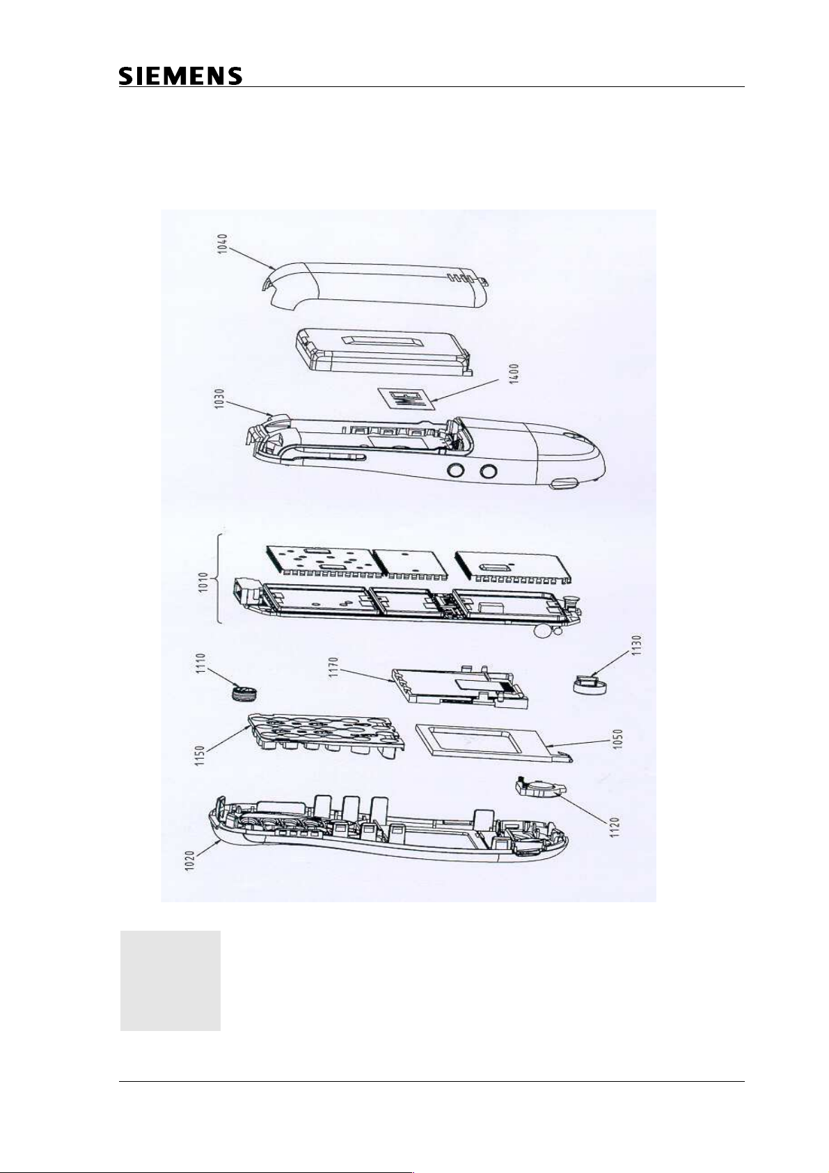
S35 Series Mechanical Diagram
FIGURE 2.1 S35I MECHANICAL DIAGRAM.
Please take note that the number(s) used here IS NOT the part number,
DO NOT used it in your spare parts purchase order.
A l w a y s r e f e r t o t h e S E R V I C E P A R T P R I C E LI S T
f o r y o u r s p a r e p a r t o r d e r .
V1.0
6
Page 11

Mechanical Concept
Note: All numbers refer to mechanical drawing in Figure 2.1.
The mechanical concept of the S35i differs in various points from the one of the other
Siemens mobile telephones.
The first thing you will experience is how the housing is locked. In S35i no screws are used
to keep the housing closed. Also inside the telephone no screws are used anymore. To
open the housing, which is kept closed by catches only, a special opening tool has been
defined. Once the phone is open the catches will be damage and a new housing need to
be used. For details on disassembly tool please refer to Photo 2.3 in this chapter.
Inside, the S35i consists of just one board (1010) which carries display module(1170),
control part and RF section of the mobile.
The display module (1170) is connected to the board by a flexible cable which is inserted
into a plug. In case the display is defective electrically or mechanically it can be exchanged
very easily.
S35i does have an external connector of a new type. Since S6 a so called “Molex”connector was used, which also offered the possibility to connect an external antenna to it.
The new “Lumberg”-connector which is used in S35i does not feature such a connection,
because the connector for external antenna is located at the back side of the upper end of
the mobile, close to the internal antenna (1130). As a consequence of this there is no
need anymore for a RF cable mounted to the board nor for a RF plug on it to connect this
cable. This improves RF-properties of the mobile and lowers production costs.
To be able to do measurements on and software update of the telephone, an adapter
cable between Molex and Lumberg connector will be available. See photos in Additional
Tools of Chapter 3.
S35i antenna (1130) is a integral part of the lower case shell (1030). The antenna can only
be changed by open up the S35i phone and replace the housing.
The S35i is a dual-band mobile operating on GSM900 and GSM1800,
the antenna is an integral part of the lower housing.
The keypad (1150), the microphone (1110) and the loudspeaker (1120) are mounted into
the upper case shell (1020). Make sure that the microphone and the earphone contact
springs are not dirty or damaged during repair process.
V1.0
7
Page 12

Hardware Concept – Block Diagram
FIGURE 2.2 S35 I BLOCK DIAGRAM.
V1.0
8
Page 13

Hardware Description
The handset consists of the following major integrated circuits:
1) E-GOLD (PMB 2850)
This IC is a combination of microprocessor and signal processor.
The microprocessor part of this component is responsible for controlling the keyboard,
SIM-Card, Flash and RAM. Furthermore it controls the power up/power down of the RF
module and sets the amplification of the PA.
The signal processor part of PMB 2800 is responsible for processing the Rx I/Q signals
(filtering, equalizing, speech and channel decoding).
Furthermore it does the speech and channel encoding and the GSMK modulation of
the Tx I/Q signals.
The coprocessor PMB 2805 is used to realize advanced features regarding coding of
the speech signal. These are:
• Halfrate-Encoding
• Halfrate-Decoding
• Enhanced Fullrate Encoding
• Enhanced Fullrate Decoding
• Voice Activity Detection
• Comfort Noise
3) GAIM (PMB 2906)
The GAIM (GAIM = GSM Analog Interfacing Module) provides the interface between
the analogue signals (I/Q, voiceband, PA-control, charging control signals) and its
digital representation.
4) Transceiver Circuit (Bright II HD155124F)
This circuit provides the following main functionalities:
• Low Noise Amplifier (LNA) with a fixed amplification of +20dB to amplify the input
RF signal.
• Mixer to mix down the RF signal to the Intermediate Frequency (IF)
• Programmable IF amplifier with a dynamic range of 60dB ( -10dB ~+50dB in steps
of 2dB).
• Mixer to mix down the IF signal to the baseband, generating and inphase (I) and a
quadrature (Q) signal.
• Offset compensation for the I/Q signals.
This circuit provides the IF synthesizer, the I/Q modulator, prescalers to regulate the RF
synthesizer and a buffer stage to feed the PA.
The antenna switch is mechanical, located in the connector for the external antenna.
V1.0
9
Page 14

Power Supply Concept
The S35i has two main power inputs:
1. Battery voltage(3.6V) connected at the battery contact
2. Charging voltage(6.5V) delivered by the different charger type(see Accessory List) via
the Lumberg connector at the bottom of the telephone.
Since the battery voltage is supplying the power supply ASIC, it is always needed to
operate the phone. You cannot switch on the handset if the battery voltage is not
present.
From the battery voltage, all other supply voltages are derived and controlled by the power
supply ASIC.
The RF power amplifier is directly connect to the battery, a bad battery with high internal
resistance can cause malfunction of the S35i phone.
The Logic module uses 1.92V, 2.65V & 2.9V generated by voltage regulators inside the
ASIC.
Furthermore, the ASIC generates the supply voltage for the SIM card and the RESET
signal for the logic devices.
The ASIC also checks the presence of the watchdog signal from the microprocessor and
provides the switching on functionality (ON_OFF button or Ignition signal).
Wrong polarity or battery voltage setting that exceed the +6.5V
could damage the phone.
Over-voltage Condition
• Battery voltage
If the supply voltage rises above 6.2V, the phone will switch off and it cannot be
switched on again before the voltage is lower than 6.2V.
If the supply voltage rises above 7V, the phone can be damaged.
• Charging Current
The charging current must not rise above 1A or a track fuse in the phone will blow. As
a result charging the battery will no longer by possible.
V1.0
10
Page 15

Be careful with NON-original SIEMENS accessories or chargers.
Make sure that the charging current is limited to value below 1A.
Battery – Charging
S35i series uses a Lithium Ion 600mAH battery pack as standard battery. It also support
the Nickel Metal Hyride (NiMH) 500mAH battery pack (For C35 phone).
PHOTO 2.3 S35i SERIES INSERTING BATTERY.
For S35i, BATT+ has a voltage level from +3.0V to 5.5V, and a BATT_TEMP contact is
used for detecting abnormal increase in temperature of the battery.
If the temperature is too high or too low, there is a high probability
that the battery is not charged. To enable the charging process
again, battery and phone needs to cools down or warm up. Battery
replacement is not required.
A v o i d s h o r t i n g t h e b a t t e r y t e r m i n a l s .
Short Circuit Protection
For the Nickel Metal Hydride battery, a polyswitch in the battery pack protecting the battery
from short circuit and it should reset by itself after some time removing the short circuit.
For the Lithium Ion battery, it is short-circuit protected by an electronics fuse. The fuse will
be activated in case a too high current is drawn. This fuse will not reset automatically.
The resetting of the battery fuse can be done with either of the following procedures:
1. Insert the battery into the S35i and then connect the rapid charger to the phone. Wait
for approximately 10 second, then the mobile can be turned on again.
2. Plug the battery separately into the desktop charger. The fuse is reset immediately or,
3. Insert the battery into the S35i and put the phone into the desktop charger. Wait for
approximately 10 second, then the mobile can be switched on.
V1.0
11
Page 16

Charging
The battery can be charged when it is inserted into the phone. The charging process is
completely controlled by the mobile. Charging can be done with any of the following
accessory:
1. Rapid charger
2. Travel charger
3. Car charger
4. Desktop charger
PHOTO 2.4 INSERT CHARGER
Photo 2.4 shows the correct way of inserting and removing the charger plug.
Deep Discharge Battery
In case of a deeply discharged battery, the voltage of the battery is too low to operate the
charging circuit and the display controller, the phone can not be turned on and the normal
charging process can not be started. No charging symbol is visible in the display.
In this case, charging the battery is divided into two different steps, which have to be run
subsequently:
a) Trickle charge for S35i Phone
Trickle charge mode is automatically started if the battery voltage is below 3.0V
when the charger is connected to the mobile. The charging current in Trickle mode
is appr. 10mA.
Trickle charge mode has to last minimum until the battery voltage has exceeded
3.2V, then the phone will switch on and the charging icon appear. During trickle
charge the charging symbol will not be visible and the telephone can not be turned
on. This is because the battery voltage is too low to operate the telephone.
Action:
Insert battery into handset and connect travel charger to the telephone. If within 4
hours the battery voltage is high enough again, the charging symbol will come up.
If the battery is discharged very deeply, the symbol may not come up and the
trickle charge time possibly has to be extended up to 24 hours.
V1.0
12
Page 17

b) Normal charge
When the battery voltage is above the a.m. value (e.g. by trickle charge) the
mobile will start the normal charging mode and show a charging symbol in the
display. * Always normal charge a new battery or a deep discharged battery for
more then 12 hours before first use.
Action:
Connect charger to the telephone (see section on Charging).
The charging symbol will come up as an indication that the normal charging
process has been started by the mobile.
V1.0
13
Page 18

Mobile Phone S35i Spare Parts Level 2
V1.0
L36880-A34-A.... see Spare Part List
Battery Cover
L36158-A34-B..
Batterie Li-Ion
L36145-K1310X127
Lower Case Shell
L36158-A34-B20
Vibra-Alert Unit
L36453-Z5-C77
Battery Contact
Spring
L36334-Z97-C113
SIM Card Reader
with
Card Holder
L36334-Z97-C111
SIM-Card Holder
L36334-Z97-C112
Microphone
L36254-Z6-C82
Button Wipp Voice
Memo
L36158-A34-C192
Button Voice Memo
L36158-A34-C191
Cover IRDA-Interface
L36158-A34-C140
Button Wipp Volume
L36158—A34-C182
Button Volume
L36158-A34-C181
RF Control Board
L36880-Q4100-B206
Buzzer Sealing
L36158-A33-C260
Display module
L36851-Z1508-A50
Cushion
L36158-A34-C103
Earphone
L36212-Z3-C34
Upper Case Shell
L36158-A34-A...
Keypad
L36158-A34-B..
14
Page 19

Disassemble the S35i
A case opener is needed to disengage the latch of the S35i casing.
PHOTO 2.5 C35/S35i CASE OPENER
The part number for this mandatory tool is F30032-P46-A1
Refer to ANNEX B of Chapter 3 for Service Equipment List.
STEP 1 & 2:
Remove the battery cover then the battery as shown in PHOTO 2.6 . Open the housing
with the opening tool and carefully pull the lower housing section off as illustrated in
PHOTO 2.7 .
V1.0
15
Page 20

PHOTO 2.6 DISASSEMBLE S35i – STEP 1 PHOTO 2.7 DISASSEMBLE S35i – STEP 2
STEP 3:
Use the Case Opener carefully disengaged the catches of the Lower housing and Upper
housing to separate the housing and the Control Board Assembly as in PHOTO 2.8
PHOTO 2.8 DISASSEMBLE S35i – STEP 3
Disassemble/Assemble of the Lower Housing Assembly
STEP 1:
V1.0
16
Page 21

Open the housing with the opening tool and carefully pull the lower housing section off as
illustrated in PHOTO 2.9
PHOTO 2.9 Lower Housing Assy – STEP 1 PHOTO 2.10 Disassembly Lower Housing – STEP 2
STEP 2:
Remove in sequence by hand the SIM Card Holder, SIM Card Reader, Battery Contact
Spring, Vibra-Alert Unit, left & right side button and the Infrared Cover as illustrated in
PHOTO 2.10
For the assembly of the Lower Housing just reverse the sequence for the disassembly.
Dis-assemble/Assemble the Control Board Assembly
STEP 1:
Open the housing with the opening tool and carefully pull the lower housing section off as
illustrated in PHOTO 2.11
V1.0
17
Page 22

PHOTO 2.11 Control Board Assy – STEP 1 PHOTO 2.12 Disassemble Control Board Assy – STEP 2
STEP 2:
Unlock the catches of the Display Module from the Control Board and move the display
module to the lower part of the PCB. Lift up carefully the retaining clip of the display
connector on the Control Board as illustrated in PHOTO 2.12
STEP 3:
Remove the Display Module and the Buzzer Sealing from the Control Board as illustrated
in PHOTO 2.13
PHOTO 2.13 Disassemble Control Board Assy – STEP 2
V1.0
18
Page 23

For Remove/Install the display module, watch out for the catches on the display module
and the guide hole of the PCB. For the assembly of the Control Board Assembly just
reverse the sequence for the disassembly.
Disassemble/Assemble of the Upper Housing Assembly
STEP 1:
Open the housing with the opening tool and carefully pull the lower housing section off as
illustrated in PHOTO 2.14
PHOTO 2.14 Upper Housing Assy – STEP 1 PHOTO 2.15 Disassemble Upper Housing – STEP 2
STEP 2:
Remove the Keypad by hand and use a fine point metal tweezers to remove the
microphone as illustrated in PHOTO 2.15
The loudspeaker is glued to the upper housing section by a foam
covered with glue on both sides. When you remove it, the foam will
V1.0
19
Page 24

be damaged. Please use new loudspeaker for assembling Upper Housing
Assembly.
For assembly of a new Upper Housing install a new earphone first, watch out for the
orientation. For install of the other parts just reverse the sequence for the disassembly.
Assemble the S35i
STEP 1:
Check that the Lower Housing Assembly, Control Board Assembly and Upper Housing
Assembly are in good order. Check if the Buzzer sealing was installed on the Control
Board.
N e w U p p e r a n d L o w e r C a s i n g m u s t b e u s e d . A l l
c o n t a c t p i n s m u s t n o t b e d i r t y , d a m a g e d o r b e n t !
I f a n y p a r t i s n o t O . K p l e a s e r e p l a c e i t w i t h a n e w
p a r t .
V1.0
20
Page 25

PHOTO 2.16 ASSEMBLE S35i – STEP 1 PHOTO 2.17 ASSEMBLE S35i – STEP 2
STEP 2:
Clear the dust on the display screen of the Display module and the Upper Housing by an
air gun. Place the Control Board Assembly in the Upper Housing as illustrated in PHOTO
2.17.
Check and ensure the display is free from dust.
STEP 3:
V1.0
21
Page 26

Close the device by putting on the Lower casing section as illustrated in PHOTO 2.18.
Hold the phone and use both hands to close the casing starting from the catches at the
top part near the antenna, watch out for leaving any finger marking on the display screen.
PHOTO 2.18 ASSEMBLE S35i – STEP 3
STEP 4:
Remove old IMEI label from the old housing using a hair-dryer for re-use of the IMEI label
or paste the new IMEI label supplied for control board replacement. Insert the battery and
put back the battery cover. Ready for testing.
PHOTO 2.19 ASSEMBLE S35i – STEP 4
D o n o t p l a c e t h e p h o n e o n t h e t a b l e
t o c l o s e u p t h e h o u s i n g a s t h e
A n t e n n a m a y b e d a m a g e .
ALL CATCHES MUST BE ENGAGED COMPLETELY!
V1.0
22
Page 27

Mobile Software Programming
Model before C25 and S35i, software used for the mobile are similar except for their
differences in the language group. Customer specific values (e.g. ringing tones etc) are
seldom, but there were some, were included in the common mobile software.
S35i and C25 has changed. There is still a common mobile software available which is
divided into language groups. However, this software does not contain the specific
settings, such as ringing tones, greeting text, short dial list etc., required by the operator(s)
or service provider(s). Therefore, it is not uncommon to have some menu item(s) differ in
different variants or are not visible at all.These settings are stored in different memory area
of the mobile and will be activated depending on the customer specific model or variant of
the phone by a separate test step during the production process.
Due to this separation of common mobile software and customer specific initialization, it is
possible to fulfill the demands of the market requiring customization and flexibility.
As a consequence the software programming process in the LSO is divided into two
different steps as followed:
1. Software update to actual version and appropriate language group
2. Programming of CUSTOMER SPECIFIC INITIALIZATION
Mobile Software Updating
The software of the mobile, S35i series, is loaded from a PC directly. Hardware
interconnection between the mobile and the PC is shown in Figure 2.20
FIGURE 2.20 S35I SERIES SOFTWARE PROGRAMMING SETUP
Because of the new type of external connector used in S35i (Lumberg type) an additional
adapter cable between mobile and boot adapter is required. Table 2.1 listed all the
hardware requirements
If you use the S35i battery dummy, then make sure that the power supply voltage is
correctly adjusted 4V and 3A rating.
V1.0
23
Page 28

Description Part No.
Adapter-Cable-Bootadapter, C25/S25/P35 V30146-A5004-D
Boot Adapter L24857-F1006-A30
IBM Compatible PC – Pentium -
TABLE 2.1 EQUIPMENT LIST FOR SOFTWARE PROGRAMMING.
SOFTWARE IS A DOS-BASED PROGRAM, IT IS
ADVISABLE TO DO THE SOFTWARE UPGRADE IN DOS
ENVIRONMENT.
Languague Groups
There are over 20 languages for the S35i series in total. These languages are divided into
groups as follows
SLG 1
English, german, french, italian, dutch, swedish, finnish,
norwegian, danish
SLG 2
English, swedish, finnish, norwegian, danish, german, french,
italian, dutch
SLG 3
English, french, italian, spanish, portuguese, german, catalan,
dutch
SLG 4
English, german, hungarian, polish, russian, bulgarian, czech,
slovakian
SLG 5
English, french, italian, arabic, greek, turkish, hebrew, bahasa,
malaysia, bahasa indonesia
SLG 6
English 2, chinese simplified, chinese traditional (For 3568i)
Note: Tegic T9 is supported in bold
TABLE 2.2 SOFTWARE LANGUAGE GROUPS.
T h i s i n f o r m a t i o n i s s u b j e c t t o c h a n g e !
Contact your Service Manager for the order number of the
right version of mobile software for your market.
The mobile software file is named using this convention:
e.g. S35_0501 Version = 05; Language Group = 1
S35_0508 Version = 05; Language Group = 8.
This executable file needs an definition or init file, named SWUP.INI, to define the
message language preferences and the hardware communication port set up.
The content of this file consists of the following text:
V1.0
S35_(Version)(LG).EXE
Language=English
COM=x
24
Page 29

Where x is the number that corresponds to the serial port that is used, either 1, 2 or 3.
Flow chart 2.1 illustrates the software programming process.
FLOWCHART 2.1 SOFTWARE PROGRAMMING. PROCESS
Customer Specific Initialization
Refer to Customization guide
V1.0
No
Yes
YesNoNo
Yes
YesNoYes
No
Plug in the Boot
Adapter to the
PC and Mobile
Connect the AC
adapter to the
Boot Adapter
Power up Boot
Adapter &
Check LED
OK
?
Check AC
Adapter
OK
?
Faulty AC
Adapter
Faulty Boot
Adapter
Power up the PC
in DOS
environment
Execute the
“Mobile S/W”
Error
?
Check
H/W setup = S/W
settings.
OK
?
Software
upgrading in
progress
Correct settings.
Error
?
Test Mobile
Take note of
error and repeat
process again
Feedback Error
to ICP CD ASC
END
25
Page 30

L S O h a s t o m a k e s u r e t h a t a ft e r r e p a i r t h e
c u s t o m e r ge t s t h e m o b i l e w i t h c o r r e c t v a r i a n t
s p e c i f i c i n i t i a l i z at i o n .
F o r m o r e i n f or m a t io n a b o u t t h e c o n f i g u r a t i o n
t o o l , r e f e r t o S e r v i c e I n f o r m a t i o n d a t e d 3 0
t h
A p r i l 1 9 9 9 , o r c o n t a c t y o u r S e r v i c e M a n a ge r .
International Mobile Equipment Identity, IMEI
The mobile equipment is uniquely identified by the International Mobile Equipment Identity,
IMEI, which consists of 15 digits. Type approval granted to a type of mobile is allocated 6
digits. The final assembly code is used to identify the final assembly plant and is assigned
with 2 digits. 6 digits have been allocated for the equipment serial number for
manufacturer and the last digit is spare.
S35i series IMEI label is accessible by removing the battery. It is illustrated in Photo 2.34.
PHOTO 2.21 S35I SERIES IMEI LABEL
On this IMEI label, Siemens has also includes the date code for production or service,
which conforms to the industrial standard DIN EN 60062. The date code comprises of 2
characters: first character denotes the Year and the second character denotes the Month.
Example: KD
Year Date Code Month Date Code
1999 L December D
2000 M January 1
2001 N February 2
TABLE 2.3 DIN EN 60062 DATE CODE
V1.0
8
26
Page 31

Phone Unblocking
When the phone is disable due to wrong entry of PHONECODE, it can be re-activated by
entering the right unblocking code. This unblocking code is derived from the IMEI number
of the mobile.
The unblocked code, also known as Master Phone Code, has to be entered in the
following format:
* # 0 0 0 3 * - - - - - - - - #
The Master Phone Code can be obtained by:
1. Fax to Siemens Hotline in Germany
Siemens AG
ICP CD SH
World Service Center, Bocholt, Germany
+49-2871-91-3007
2. Fax to Siemens Hotline in Singapore
Siemens Advanced Engineering Pte Ltd
ICP CD ASC
Ms Ginny Siew
+65-842-6641
3. Internet Solution
A password protected homepage where LSO can enter IMEI number of a disable phone.
The generated Master Code will then be presented for unblocking purpose. This service is
offered to all LSOs.
V1.0
27
Page 32

PHOTO 2.22 INTERNET PAGE
PHOTO 2.23 INTERNET PAGE: MASTER PHONE CODE
Contact your Service Manager for more information regarding
setting up of the INTERNET SOLUTION & its installation
procedure, ASC/T002/98.
V1.0
28
Page 33

Disclaimer: This content is subjected to change without notice.
Copyright 1999 Siemens Advanced Engineering Pte Ltd
ICP CD Asia Service Center,
164, Kallang Way, #04-22, Kolam Ayer Industrial Estate, Singapore 349248
Author: Tan Guan San.
Phone +65-8454822 • Fax +65-8426641
First Print: March, 00
Revised Print: May,00
Date Print: May 26, 2000
The reproduction and transmission of this document to unauthorized parties is not permitted without written
authority. Offender will be liable for damages.
V1.0
29
 Loading...