

Page 1

User Manual
SURPASS hiD 6615 S223/S323 R1.5
UMN:CLI
A50010-Y3-C150-2-7619
Page 2

UMN:CLI User Manual
SURPASS hiD 6615 S223/S323 R1.5
Important Notice on Product Safety
Elevated voltages are inevitably present at specific points in this electrical equipment. Some of the
parts may also have elevated operating temperatures.
Non-observance of these conditions and the safety instructions can result in personal injury or in
property damage.
Therefore, only trained and qualified personnel may install and maintain the system.
The system complies with the standard EN 60950-1 / IEC 60950-1. All equipment connected has to
comply with the applicable safety standards.
The same text in German:
Wichtiger Hinweis zur Produktsicherheit
In elektrischen Anlagen stehen zwangsläufig bestimmte Teile der Geräte unter Spannung. Einige
Teile können auch eine hohe Betriebstemperatur aufweisen.
Eine Nichtbeachtung dieser Situation und der Warnungshinweise kann zu Körperverletzungen und
Sachschäden führen.
Deshalb wird vorausgesetzt, dass nur geschultes und qualifiziertes Personal die Anlagen installiert
und wartet.
Das System entspricht den Anforderungen der EN 60950-1 / IEC 60950-1. Angeschlossene Geräte
müssen die zutreffenden Sicherheitsbestimmungen erfüllen.
Trademarks:
All designations used in this document can be trademarks, the use of which by third parties for their
own purposes could violate the rights of their owners.
Copyright (C) Siemens AG 2005-2006.
Issued by the Communications Group
Hofmannstraße 51
D-81359 München
Technical modifications possible.
Technical specifications and features are binding only insofar as
they are specifically and expressly agreed upon in a written contract.
2 A50010-Y3-C150-2-7619
Page 3

User Manual UMN:CLI
SURPASS hiD 6615 S223/S323 R1.5
Reason for Update
Summary: System software upgrade added
Details:
Chapter/Section Reason for Update
11 System software upgrade added
Issue History
Issue
Number
01 07/2006 Initial release
02 08/2006 System software upgrade added
Date of Issue Reason for Update
A50010-Y3-C150-2-7619 3
Page 4

UMN:CLI User Manual
SURPASS hiD 6615 S223/S323 R1.5
This document consists of a total 381 pages. All pages are issue 2.
Contents
1 Introduction ....................................................................................................... 20
1.1 Audience........................................................................................................... 20
1.2 Document Structure.......................................................................................... 20
1.3 Document Convention ...................................................................................... 21
1.4 Document Notation ........................................................................................... 21
1.5 CE Declaration of Conformity ........................................................................... 21
1.6 GPL/LGPL Warranty and Liability Exclusion .................................................... 22
2 System Overview.............................................................................................. 23
2.1 System Features............................................................................................... 24
3 Command Line Interface (CLI) ......................................................................... 27
3.1 Command Mode ............................................................................................... 27
3.1.1 Privileged EXEC View Mode ............................................................................ 29
3.1.2 Privileged EXEC Enable Mode......................................................................... 29
3.1.3 Global Configuration Mode............................................................................... 29
3.1.4 Bridge Configuration Mode............................................................................... 30
3.1.5 Rule Configuration Mode.................................................................................. 31
3.1.6 DHCP Configuration Mode ............................................................................... 32
3.1.7 DHCP Option 82 Configuration Mode .............................................................. 32
3.1.8 Interface Configuration Mode ........................................................................... 33
3.1.9 RMON Configuration Mode .............................................................................. 33
3.1.10 Router Configuration Mode .............................................................................. 34
3.1.11 VRRP Configuration Mode ............................................................................... 34
3.1.12 Route-Map Configuration Mode ....................................................................... 35
3.2 Useful Tips........................................................................................................ 36
3.2.1 Listing Available Commands ............................................................................ 36
3.2.2 Calling Command History................................................................................. 37
3.2.3 Using Abbreviation............................................................................................ 38
3.2.4 Using Command of Privileged EXEC Enable Mode......................................... 38
3.2.5 Exit Current Command Mode ........................................................................... 39
4 System Connection and IP Address ................................................................. 40
4.1 System Connection........................................................................................... 40
4.1.1 System Login .................................................................................................... 40
4.1.2 Password for Privileged EXEC Mode............................................................... 41
4.1.3 Changing Login Password................................................................................ 42
4.1.4 Management for System Account..................................................................... 42
4.1.4.1 Creating System Account ................................................................................. 42
4.1.4.2 Configuring Security Level................................................................................ 43
4.1.5 Limiting Number of User................................................................................... 47
4.1.6 Telnet Access.................................................................................................... 47
4.1.7 Auto Log-out ..................................................................................................... 48
4.1.8 System Rebooting ............................................................................................ 48
4.1.8.1 Manual System Rebooting ............................................................................... 48
4.1.8.2 Auto System Rebooting.................................................................................... 49
4.2 System Authentication ...................................................................................... 49
4.2.1 Authentication Method...................................................................................... 50
4 A50010-Y3-C150-2-7619
Page 5

User Manual UMN:CLI
SURPASS hiD 6615 S223/S323 R1.5
4.2.2 Authentication Interface.....................................................................................50
4.2.3 Primary Authentication Method .........................................................................50
4.2.4 RADIUS Server .................................................................................................51
4.2.4.1 RADIUS Server for System Authentication .......................................................51
4.2.4.2 RADIUS Server Priority .....................................................................................51
4.2.4.3 Timeout of Authentication Request....................................................................51
4.2.4.4 Frequency of Retransmit ...................................................................................52
4.2.5 TACACS Server.................................................................................................52
4.2.5.1 TACACS Server for System Authentication.......................................................52
4.2.5.2 TACACS Server Priority ....................................................................................52
4.2.5.3 Timeout of Authentication Request....................................................................52
4.2.5.4 Additional TACACS+ Configuration ...................................................................53
4.2.6 Accounting Mode...............................................................................................54
4.2.7 Displaying System Authentication .....................................................................54
4.2.8 Sample Configuration........................................................................................55
4.3 Assigning IP Address.........................................................................................56
4.3.1 Enabling Interface..............................................................................................57
4.3.2 Disabling Interface.............................................................................................57
4.3.3 Assigning IP Address to Network Interface .......................................................58
4.3.4 Static Route and Default Gateway ....................................................................58
4.3.5 Displaying Forwarding Information Base(FIB) Table .........................................59
4.3.6 Forwarding Information Base(FIB) Retain.........................................................59
4.3.7 Displaying Interface ...........................................................................................60
4.3.8 Sample Configuration........................................................................................60
4.4 SSH (Secure Shell) ...........................................................................................61
4.4.1 SSH Server........................................................................................................61
4.4.1.1 Enabling SSH Server.........................................................................................61
4.4.1.2 Displaying On-line SSH Client...........................................................................61
4.4.1.3 Disconnecting SSH Client .................................................................................61
4.4.1.4 Displaying Connection History of SSH Client....................................................61
4.4.1.5 Assigning Specific Authentication Key...............................................................62
4.4.2 SSH Client .........................................................................................................62
4.4.2.1 Login to SSH Server..........................................................................................62
4.4.2.2 File Copy ...........................................................................................................62
4.4.2.3 Configuring Authentication Key .........................................................................62
4.5 802.1x Authentication ........................................................................................64
4.5.1 802.1x Authentication ........................................................................................65
4.5.1.1 Enabling 802.1x.................................................................................................65
4.5.1.2 Configuring RADIUS Server..............................................................................65
4.5.1.3 Configuring Authentication Mode ......................................................................66
4.5.1.4 Authentication Port ............................................................................................67
4.5.1.5 Force Authorization............................................................................................67
4.5.1.6 Configuring Interval for Retransmitting Request/Identity Packet ......................67
4.5.1.7 Configuring Number of Request to RADIUS Server .........................................68
4.5.1.8 Configuring Interval of Request to RADIUS Server ..........................................68
4.5.2 802.1x Re-Authentication ..................................................................................68
4.5.2.1 Enabling 802.1x Re-Authentication ...................................................................68
4.5.2.2 Configuring the Interval of Re-Authentication ...................................................69
4.5.2.3 Configuring the Interval of Requesting Re-authentication.................................69
4.5.2.4 802.1x Re-authentication ..................................................................................69
4.5.3 Initializing Authentication Status ........................................................................70
A50010-Y3-C150-2-7619 5
Page 6

UMN:CLI User Manual
SURPASS hiD 6615 S223/S323 R1.5
4.5.4 Applying Default Value...................................................................................... 70
4.5.5 Displaying 802.1x Configuration....................................................................... 70
4.5.6 802.1x User Authentication Statistic ................................................................. 70
4.5.7 Sample Configuration ....................................................................................... 71
5 Port Configuration............................................................................................. 73
5.1 Port Basic ......................................................................................................... 73
5.1.1 Selecting Port Type........................................................................................... 73
5.2 Ethernet Port Configuration .............................................................................. 74
5.2.1 Enabling Ethernet Port ..................................................................................... 74
5.2.2 Auto-negotiation................................................................................................ 75
5.2.3 Transmit Rate ................................................................................................... 75
5.2.4 Duplex Mode..................................................................................................... 76
5.2.5 Flow Control...................................................................................................... 76
5.2.6 Port Description ................................................................................................ 77
5.2.7 Traffic Statistics................................................................................................. 78
5.2.7.1 The Packets Statistics....................................................................................... 78
5.2.7.2 The CPU statistics ............................................................................................ 79
5.2.7.3 The Protocol statistics....................................................................................... 79
5.2.8 Port Status ........................................................................................................ 80
5.2.9 Initializing Port Statistics................................................................................... 80
5.3 Port Mirroring .................................................................................................... 80
6 System Environment ........................................................................................ 83
6.1 Environment Configuration ............................................................................... 83
6.1.1 Host Name........................................................................................................ 83
6.1.2 Time and Date .................................................................................................. 83
6.1.3 Time Zone......................................................................................................... 84
6.1.4 Network Time Protocol ..................................................................................... 84
6.1.5 NTP (Network Time Protocol)........................................................................... 85
6.1.6 Simple Network Time Protocol (SNTP) ............................................................ 85
6.1.7 Terminal Configuration...................................................................................... 86
6.1.8 Login Banner .................................................................................................... 87
6.1.9 DNS Server....................................................................................................... 87
6.1.10 Fan Operation................................................................................................... 88
6.1.11 Disabling Daemon Operation ........................................................................... 88
6.1.12 System Threshold............................................................................................. 88
6.1.12.1 CPU Load ......................................................................................................... 88
6.1.12.2 Port Traffic ........................................................................................................ 89
6.1.12.3 Fan Operation................................................................................................... 89
6.1.12.4 System Temperature......................................................................................... 90
6.1.12.5 System Memory................................................................................................ 90
6.1.13 Enabling FTP Server ........................................................................................ 90
6.1.14 Assigning IP Address of FTP Client.................................................................. 91
6.2 Configuration Management .............................................................................. 91
6.2.1 Displaying System Configuration...................................................................... 91
6.2.2 Saving System Configuration ........................................................................... 92
6.2.3 Auto-Saving ...................................................................................................... 92
6.2.4 System Configuration File ................................................................................ 92
6.2.5 Restoring Default Configuration ....................................................................... 93
6.3 System Management........................................................................................ 94
6.3.1 Network Connection ......................................................................................... 94
6 A50010-Y3-C150-2-7619
Page 7

User Manual UMN:CLI
SURPASS hiD 6615 S223/S323 R1.5
6.3.2 IP ICMP Source-Routing ...................................................................................97
6.3.3 Tracing Packet Route ........................................................................................98
6.3.4 Displaying User Connecting to System .............................................................99
6.3.5 MAC Table .........................................................................................................99
6.3.6 Configuring Ageing time ..................................................................................100
6.3.7 Running Time of System .................................................................................100
6.3.8 System Information..........................................................................................100
6.3.9 System Memory Information ...........................................................................101
6.3.10 CPU packet limit ..............................................................................................101
6.3.11 Average of CPU Load......................................................................................101
6.3.12 Running Process .............................................................................................101
6.3.13 Displaying System Image................................................................................102
6.3.14 Displaying Installed OS ...................................................................................102
6.3.15 Default OS .......................................................................................................102
6.3.16 Switch Status...................................................................................................103
6.3.17 Tech Support ...................................................................................................103
7 Network Management .....................................................................................104
7.1 Simple Network Management Protocol (SNMP) .............................................104
7.1.1 SNMP Community ...........................................................................................104
7.1.2 Information of SNMP Agent .............................................................................105
7.1.3 SNMP Com2sec ..............................................................................................106
7.1.4 SNMP Group ...................................................................................................106
7.1.5 SNMP View Record.........................................................................................107
7.1.6 Permission to Access SNMP View Record .....................................................107
7.1.7 SNMP Version 3 User......................................................................................108
7.1.8 SNMP Trap ......................................................................................................108
7.1.8.1 SNMP Trap Host..............................................................................................109
7.1.8.2 SNMP Trap Mode............................................................................................109
7.1.8.3 Enabling SNMP Trap.......................................................................................110
7.1.8.4 Disabling SNMP Trap ...................................................................................... 111
7.1.8.5 Displaying SNMP Trap ....................................................................................112
7.1.9 SNMP Alarm ....................................................................................................112
7.1.9.1 Enabling Alarm Notification ............................................................................. 11 2
7.1.9.2 Default Alarm Severity .....................................................................................113
7.1.9.3 Alarm Severity Criterion...................................................................................11 3
7.1.9.4 Generic Alarm Severity.................................................................................... 11 4
7.1.9.5 ADVA Alarm Severity .......................................................................................115
7.1.9.6 ERP Alarm Severity .........................................................................................116
7.1.9.7 STP Guard Alarm Severity ..............................................................................117
7.1.10 Displaying SNMP Configuration ......................................................................11 7
7.1.11 Disabling SNMP ..............................................................................................118
7.2 Operation, Administration and Maintenance (OAM)........................................119
7.2.1 OAM Loopback................................................................................................119
7.2.2 Local OAM Mode.............................................................................................120
7.2.3 OAM Unidirection ............................................................................................120
7.2.4 Remote OAM...................................................................................................120
7.2.5 Displaying OAM Configuration ........................................................................121
7.3 Link Layer Discovery Protocol (LLDP) ............................................................123
7.3.1 LLDP Operation...............................................................................................123
7.3.2 LLDP Operation Type ......................................................................................123
A50010-Y3-C150-2-7619 7
Page 8

UMN:CLI User Manual
SURPASS hiD 6615 S223/S323 R1.5
7.3.3 Basic TLV........................................................................................................ 123
7.3.4 LLDP Message ............................................................................................... 124
7.3.5 Interval and Delay Time.................................................................................. 124
7.3.6 Displaying LLDP Configuration....................................................................... 125
7.4 Remote Monitoring (RMON)........................................................................... 126
7.4.1 RMON History................................................................................................. 126
7.4.1.1 Source Port of Statistical Data........................................................................ 127
7.4.1.2 Subject of RMON History ............................................................................... 127
7.4.1.3 Number of Sample Data ................................................................................. 127
7.4.1.4 Interval of Sample Inquiry............................................................................... 127
7.4.1.5 Activating RMON History................................................................................ 128
7.4.1.6 Deleting Configuration of RMON History........................................................ 128
7.4.1.7 Displaying RMON History............................................................................... 128
7.4.2 RMON Alarm................................................................................................... 129
7.4.2.1 Subject of RMON Alarm ................................................................................. 129
7.4.2.2 Object of Sample Inquiry ................................................................................ 130
7.4.2.3 Absolute Comparison and Delta Comparison ................................................ 130
7.4.2.4 Upper Bound of Threshold ............................................................................. 130
7.4.2.5 Lower Bound of Threshold ............................................................................. 131
7.4.2.6 Configuring Standard of the First Alarm.......................................................... 131
7.4.2.7 Interval of Sample Inquiry............................................................................... 131
7.4.2.8 Activating RMON Alarm.................................................................................. 132
7.4.2.9 Deleting Configuration of RMON Alarm.......................................................... 132
7.4.2.10 Displaying RMON Alarm................................................................................. 132
7.4.3 RMON Event................................................................................................... 132
7.4.3.1 Event Community ........................................................................................... 132
7.4.3.2 Event Description............................................................................................ 133
7.4.3.3 Subject of RMON Event ................................................................................. 133
7.4.3.4 Event Type...................................................................................................... 133
7.4.3.5 Activating RMON Event.................................................................................. 133
7.4.3.6 Deleting Configuration of RMON Event.......................................................... 134
7.4.3.7 Displaying RMON Event................................................................................. 134
7.5 Syslog ............................................................................................................. 135
7.5.1 Syslog Output Level ....................................................................................... 135
7.5.2 Facility Code ................................................................................................... 137
7.5.3 Syslog Bind Address....................................................................................... 137
7.5.4 Debug Message for Remote Terminal ............................................................ 138
7.5.5 Disabling Syslog ............................................................................................. 138
7.5.6 Displaying Syslog Message............................................................................ 138
7.5.7 Displaying Syslog Configuration..................................................................... 138
7.6 Rule and QoS ................................................................................................. 139
7.6.1 How to Operate Rule and QoS....................................................................... 139
7.6.2 Rule Configuration.......................................................................................... 140
7.6.2.1 Rule Creation.................................................................................................. 140
7.6.2.2 Rule Priority .................................................................................................... 140
7.6.2.3 Packet Classification ...................................................................................... 141
7.6.2.4 Rule Action...................................................................................................... 143
7.6.2.5 Applying Rule.................................................................................................. 145
7.6.2.6 Modifying and Deleting Rule........................................................................... 145
7.6.2.7 Displaying Rule............................................................................................... 146
7.6.3 QoS................................................................................................................. 146
8 A50010-Y3-C150-2-7619
Page 9

User Manual UMN:CLI
SURPASS hiD 6615 S223/S323 R1.5
7.6.3.1 Scheduling Algorithm.......................................................................................147
7.6.3.2 Qos Weight......................................................................................................149
7.6.3.3 802.1p Priory-to-queue Mapping.....................................................................149
7.6.3.4 Queue Parameter ............................................................................................150
7.6.3.5 Displaying QoS................................................................................................150
7.6.4 Admin Access Rule..........................................................................................150
7.6.4.1 Rule Creation...................................................................................................151
7.6.4.2 Rule Priority .....................................................................................................151
7.6.4.3 Packet Classification .......................................................................................152
7.6.4.4 Rule Action ......................................................................................................153
7.6.4.5 Applying Rule ..................................................................................................153
7.6.4.6 Modifying and Deleting Rule ...........................................................................154
7.6.4.7 Displaying Rule................................................................................................154
7.7 NetBIOS Filtering.............................................................................................155
7.8 Martian Filtering...............................................................................................156
7.9 Max Host .........................................................................................................156
7.9.1 Max New Hosts ...............................................................................................157
7.10 Port Security ....................................................................................................158
7.10.1 Port Security on Port .......................................................................................158
7.10.2 Port Security Aging..........................................................................................160
7.11 MAC Table .......................................................................................................161
7.12 MAC Filtering...................................................................................................163
7.12.1 Default Policy of MAC Filtering........................................................................163
7.12.2 Adding Policy of MAC Filter.............................................................................163
7.12.3 Deleting MAC Filter Policy...............................................................................164
7.12.4 Listing of MAC Filter Policy .............................................................................164
7.12.5 Displaying MAC Filter Policy ...........................................................................164
7.13 Address Resolution Protocol (ARP) ................................................................165
7.13.1 ARP Table........................................................................................................165
7.13.1.1 Registering ARP Table.....................................................................................166
7.13.1.2 Displaying ARP Table ......................................................................................166
7.13.2 ARP Alias.........................................................................................................167
7.13.3 ARP Inspection................................................................................................167
7.13.4 Gratuitous ARP................................................................................................169
7.13.5 Proxy-ARP.......................................................................................................169
7.14 ICMP Message Control ...................................................................................169
7.14.1 Blocking Echo Reply Message........................................................................170
7.14.2 Interval for Transmit ICMP Message ...............................................................170
7.14.3 Transmitting ICMP Redirect Message.............................................................172
7.14.4 The policy of unreached messages.................................................................173
7.15 IP TCP Flag Control.........................................................................................173
7.15.1 RST Configuration ...........................................................................................173
7.15.2 SYN Configuration...........................................................................................174
7.16 Packet Dump ...................................................................................................174
7.16.1 Verifying Packet Dump ....................................................................................174
7.16.1.1 Packet Dump by Protocol................................................................................175
7.16.1.2 Packet Dump with Option................................................................................175
7.16.2 Debug Packet Dump .......................................................................................177
7.17 Displaying the usage of the packet routing table.............................................177
8 System Main Functions ...................................................................................178
A50010-Y3-C150-2-7619 9
Page 10

UMN:CLI User Manual
SURPASS hiD 6615 S223/S323 R1.5
8.1 VLAN .............................................................................................................. 178
8.1.1 Port-Based VLAN ........................................................................................... 179
8.1.1.1 Creating VLAN................................................................................................ 180
8.1.1.2 Specifying PVID.............................................................................................. 180
8.1.1.3 Assigning Port to VLAN .................................................................................. 180
8.1.1.4 Deleting VLAN ................................................................................................ 180
8.1.1.5 Displaying VLAN............................................................................................. 181
8.1.2 Protocol-Based VLAN..................................................................................... 181
8.1.3 MAC address-based VLAN ............................................................................ 181
8.1.4 Subnet-based VLAN....................................................................................... 182
8.1.5 Tagged VLAN.................................................................................................. 182
8.1.6 VLAN Description ........................................................................................... 183
8.1.7 Displaying VLAN Information.......................................................................... 183
8.1.8 QinQ ............................................................................................................... 184
8.1.8.1 Double Tagging Operation .............................................................................. 185
8.1.8.2 Double Tagging Configuration ........................................................................ 185
8.1.8.3 TPID Configuration ......................................................................................... 186
8.1.9 Layer 2 Isolation ............................................................................................. 186
8.1.9.1 Port Isolation................................................................................................... 187
8.1.9.2 Shared VLAN.................................................................................................. 187
8.1.10 VLAN Translation............................................................................................ 189
8.1.11 Sample Configuration ..................................................................................... 189
8.2 Link Aggregation............................................................................................. 192
8.2.1 Port Trunk ....................................................................................................... 193
8.2.1.1 Configuring Port Trunk.................................................................................... 193
8.2.1.2 Disabling Port Trunk ....................................................................................... 194
8.2.1.3 Displaying Port Trunk Configuration............................................................... 194
8.2.2 Link Aggregation Control Protocol (LACP) ..................................................... 194
8.2.2.1 Configuring LACP........................................................................................... 195
8.2.2.2 Packet Route .................................................................................................. 195
8.2.2.3 Operating Mode of Member Port .................................................................... 196
8.2.2.4 Identifying Member Ports within LACP........................................................... 197
8.2.2.5 BPDU Transmission Rate............................................................................... 197
8.2.2.6 Key value of Member Port .............................................................................. 197
8.2.2.7 Priority of Member Port................................................................................... 198
8.2.2.8 Priority of Switch ............................................................................................. 198
8.2.2.9 Displaying LACP Configuration ...................................................................... 199
8.3 Spanning-Tree Protocol (STP)........................................................................ 200
8.3.1 STP Operation ................................................................................................ 201
8.3.2 RSTP Operation ............................................................................................. 205
8.3.3 MSTP Operation............................................................................................. 209
8.3.4 Configuring STP/RSTP/MSTP/PVSTP/PVRSTP Mode (Required) ................211
8.3.5 Configuring STP/RSTP/MSTP........................................................................ 212
8.3.5.1 Activating STP/RSTP/MSTP .......................................................................... 212
8.3.5.2 Root Switch..................................................................................................... 212
8.3.5.3 Path-cost......................................................................................................... 212
8.3.5.4 Port-priority ..................................................................................................... 213
8.3.5.5 MST Region.................................................................................................... 214
8.3.5.6 MSTP Protocol................................................................................................ 215
8.3.5.7 Point-to-point MAC Parameters...................................................................... 215
8.3.5.8 Edge Ports ...................................................................................................... 215
10 A50010-Y3-C150-2-7619
Page 11

User Manual UMN:CLI
SURPASS hiD 6615 S223/S323 R1.5
8.3.5.9 Displaying Configuration .................................................................................216
8.3.6 Configuring PVSTP/PVRSTP..........................................................................217
8.3.6.1 Activating PVSTP/PVRSTP.............................................................................217
8.3.6.2 Root Switch .....................................................................................................218
8.3.6.3 Path-cost .........................................................................................................218
8.3.6.4 Port-priority ......................................................................................................218
8.3.7 Root Guard ......................................................................................................219
8.3.8 Restarting Protocol Migration ..........................................................................219
8.3.9 Bridge Protocol Data Unit Configuration .........................................................220
8.3.9.1 Hello Time........................................................................................................220
8.3.9.2 Forward Delay .................................................................................................221
8.3.9.3 Max Age...........................................................................................................221
8.3.9.4 BPDU Hop .......................................................................................................222
8.3.9.5 BPDU Filter......................................................................................................222
8.3.9.6 BPDU Guard....................................................................................................222
8.3.9.7 Self Loop Detection .........................................................................................223
8.3.9.8 Displaying BPDU Configuration ......................................................................224
8.3.10 Sample Configuration......................................................................................225
8.4 Virtual Router Redundancy Protocol (VRRP)..................................................227
8.4.1 Configuring VRRP ...........................................................................................228
8.4.1.1 Associated IP Address.....................................................................................228
8.4.1.2 Access to Associated IP Address ....................................................................229
8.4.1.3 Master Router and Backup Router..................................................................229
8.4.1.4 VRRP Track Function......................................................................................231
8.4.1.5 Authentication Password.................................................................................232
8.4.1.6 Preempt ...........................................................................................................233
8.4.1.7 VRRP Statistics ...............................................................................................234
8.5 Rate Limit ........................................................................................................234
8.5.1 Configuring Rate Limit .....................................................................................235
8.5.2 Sample Configuration......................................................................................235
8.6 Flood Guard.....................................................................................................236
8.6.1 Configuring Flood-Guard.................................................................................236
8.6.2 Sample Configuration......................................................................................237
8.7 Bandwidth........................................................................................................237
8.8 Dynamic Host Configuration Protocol (DHCP)................................................238
8.8.1 DHCP Server...................................................................................................239
8.8.1.1 DHCP Pool Creation........................................................................................240
8.8.1.2 DHCP Subnet ..................................................................................................240
8.8.1.3 Range of IP Address........................................................................................240
8.8.1.4 Default Gateway ..............................................................................................241
8.8.1.5 IP Lease Time..................................................................................................241
8.8.1.6 DNS Server .....................................................................................................242
8.8.1.7 Manual Binding................................................................................................242
8.8.1.8 Domain Name..................................................................................................243
8.8.1.9 DHCP Server Option .......................................................................................243
8.8.1.10 Static Mapping.................................................................................................243
8.8.1.11 Recognition of DHCP Client ............................................................................243
8.8.1.12 IP Address Validation.......................................................................................244
8.8.1.13 Authorized ARP ...............................................................................................244
8.8.1.14 Prohibition of 1:N IP Address Assignment.......................................................245
8.8.1.15 Ignoring BOOTP Request................................................................................245
A50010-Y3-C150-2-7619 11
Page 12

UMN:CLI User Manual
SURPASS hiD 6615 S223/S323 R1.5
8.8.1.16 DHCP Packet Statistics .................................................................................. 245
8.8.1.17 Displaying DHCP Pool Configuration ............................................................. 246
8.8.2 DHCP Address Allocation with Option 82....................................................... 247
8.8.2.1 DHCP Class Capability................................................................................... 247
8.8.2.2 DHCP Class Creation..................................................................................... 247
8.8.2.3 Relay Agent Information Pattern..................................................................... 247
8.8.2.4 Associating DHCP Class ................................................................................ 248
8.8.2.5 Range of IP Address for DHCP Class ............................................................ 248
8.8.3 DHCP Lease Database .................................................................................. 249
8.8.3.1 DHCP Database Agent................................................................................... 249
8.8.3.2 Displaying DHCP Lease Status ...................................................................... 249
8.8.3.3 Deleting DHCP Lease Database .................................................................... 250
8.8.4 DHCP Relay Agent ......................................................................................... 250
8.8.4.1 Packet Forwarding Address............................................................................ 251
8.8.4.2 Smart Relay Agent Forwarding....................................................................... 251
8.8.5 DHCP Option 82............................................................................................. 252
8.8.5.1 Enabling DHCP Option 82.............................................................................. 253
8.8.5.2 Option 82 Sub-Option..................................................................................... 253
8.8.5.3 Option 82 Reforwarding Policy ....................................................................... 254
8.8.5.4 Option 82 Trust Policy .................................................................................... 254
8.8.5.5 Simplified DHCP Option 82 ............................................................................ 255
8.8.6 DHCP Client ................................................................................................... 256
8.8.6.1 Enabling DHCP Client .................................................................................... 256
8.8.6.2 DHCP Client ID............................................................................................... 256
8.8.6.3 DHCP Class ID ............................................................................................... 256
8.8.6.4 Host Name...................................................................................................... 256
8.8.6.5 IP Lease Time................................................................................................. 257
8.8.6.6 Requesting Option.......................................................................................... 257
8.8.6.7 Forcing Release or Renewal of DHCP Lease ................................................ 257
8.8.6.8 Displaying DHCP Client Configuration ........................................................... 257
8.8.7 DHCP Snooping ............................................................................................. 258
8.8.7.1 Enabling DHCP Snooping .............................................................................. 258
8.8.7.2 DHCP Trust State ........................................................................................... 258
8.8.7.3 DHCP Rate Limit ............................................................................................ 259
8.8.7.4 DHCP Lease Limit .......................................................................................... 259
8.8.7.5 Source MAC Address Verification................................................................... 259
8.8.7.6 DHCP Snooping Database Agent................................................................... 260
8.8.7.7 Displaying DHCP Snooping Configuration ..................................................... 261
8.8.8 IP Source Guard ............................................................................................. 261
8.8.8.1 Enabling IP Source Guard.............................................................................. 261
8.8.8.2 Static IP Source Binding ................................................................................. 262
8.8.8.3 Displaying IP Source Guard Configuration..................................................... 262
8.8.9 DHCP Filtering................................................................................................ 263
8.8.9.1 DHCP Packet Filtering.................................................................................... 263
8.8.9.2 DHCP Server Packet Filtering ........................................................................ 263
8.8.10 Debugging DHCP ........................................................................................... 264
8.9 Ethernet Ring Protection (ERP)...................................................................... 265
8.9.1 ERP Operation................................................................................................ 265
8.9.2 Loss of Test Packet (LOTP)............................................................................ 267
8.9.3 Configuring ERP............................................................................................. 267
8.9.3.1 ERP Domain ................................................................................................... 267
12 A50010-Y3-C150-2-7619
Page 13

User Manual UMN:CLI
SURPASS hiD 6615 S223/S323 R1.5
8.9.3.2 RM Node .........................................................................................................268
8.9.3.3 Port of ERP domain.........................................................................................268
8.9.3.4 Protected VLAN...............................................................................................268
8.9.3.5 Protected Activation.........................................................................................268
8.9.3.6 Manual Switch to Secondary...........................................................................269
8.9.3.7 Wait-to-Restore Time.......................................................................................269
8.9.3.8 Learning Disable Time.....................................................................................269
8.9.3.9 Test Packet Interval .........................................................................................269
8.9.3.10 Displaying ERP Configuration .........................................................................270
8.10 Stacking...........................................................................................................270
8.10.1 Switch Group ...................................................................................................271
8.10.2 Designating Master and Slave Switch.............................................................271
8.10.3 Disabling Stacking ...........................................................................................272
8.10.4 Displaying Stacking Status ..............................................................................272
8.10.5 Accessing to Slave Switch from Master Switch ..............................................272
8.10.6 Sample Configuration ......................................................................................272
8.11 Broadcast Storm Control .................................................................................274
8.12 Jumbo-frame Capacity ....................................................................................275
8.13 Blocking Direct Broadcast ...............................................................................276
8.14 Maximum Transmission Unit (MTU)................................................................276
9 IP Multicast ......................................................................................................278
9.1 Multicast Routing Information Base.................................................................279
9.1.1 Enabling Multicast Routing (Required)............................................................279
9.1.2 Limitation of MRIB Routing Entry ....................................................................279
9.1.3 Clearing MRIB Information ..............................................................................280
9.1.4 Displaying MRIB Information...........................................................................281
9.1.5 Multicast Time-To-Live Threshold....................................................................281
9.1.6 MRIB Debug ....................................................................................................281
9.1.7 Multicast Aging ................................................................................................282
9.2 Internet Group Management Protocol (IGMP) ................................................283
9.2.1 IGMP Basic Configuration ...............................................................................283
9.2.1.1 IGMP Version per Interface .............................................................................283
9.2.1.2 Removing IGMP Entry.....................................................................................284
9.2.1.3 IGMP Debug....................................................................................................284
9.2.1.4 IGMP Robustness Value .................................................................................284
9.2.2 IGMP Version 2 ...............................................................................................284
9.2.2.1 IGMP Static Join Setting..................................................................................284
9.2.2.2 Maximum Number of Groups ..........................................................................285
9.2.2.3 IGMP Query Configuration ..............................................................................285
9.2.2.4 IGMP v2 Fast Leave........................................................................................287
9.2.2.5 Displaying the IGMP Configuration .................................................................287
9.2.3 L2 MFIB ...........................................................................................................288
9.2.4 IGMP Snooping Basic Configuration...............................................................288
9.2.4.1 Enabling IGMP Snooping per VLAN ...............................................................288
9.2.4.2 Robustness Count for IGMP v2 Snooping ......................................................289
9.2.5 IGMP v2 Snooping ..........................................................................................289
9.2.5.1 IGMP v2 Snooping Fast Leave .......................................................................290
9.2.5.2 IGMP v2 Snooping Querier .............................................................................291
9.2.5.3 IGMP v2 Snooping Last-Member-Interval.......................................................293
9.2.5.4 IGMP v2 Snooping Report Method .................................................................294
A50010-Y3-C150-2-7619 13
Page 14

UMN:CLI User Manual
SURPASS hiD 6615 S223/S323 R1.5
9.2.5.5 Mrouter Port.................................................................................................... 294
9.2.5.6 Multicast TCN Flooding .................................................................................. 295
9.2.6 IGMP v3 Snooping.......................................................................................... 297
9.2.6.1 IGMP Snooping Version ................................................................................. 297
9.2.6.2 Join Host Management................................................................................... 297
9.2.6.3 Immediate Block ............................................................................................. 298
9.2.7 Multicast VLAN Registration (MVR) ............................................................... 298
9.2.7.1 Enabling MVR................................................................................................. 299
9.2.7.2 MVR Group Address....................................................................................... 299
9.2.7.3 MVR IP Address ............................................................................................. 299
9.2.7.4 Send and Receive Port................................................................................... 300
9.2.7.5 Displaying MVR Configuration........................................................................ 300
9.2.8 IGMP Filtering and Throttling.......................................................................... 300
9.2.8.1 Creating IGMP Profile..................................................................................... 301
9.2.8.2 Policy of IGMP Profile..................................................................................... 301
9.2.8.3 Group Range of IGMP Profile......................................................................... 301
9.2.8.4 Applying IGMP Profile to the Filter Port.......................................................... 302
9.2.8.5 Max Number of IGMP Join Group .................................................................. 302
9.2.9 Displaying IGMP Snooping Table ................................................................... 303
9.3 PIM-SM (Protocol Independent Multicast-Sparse Mode) ............................... 303
9.3.1 PIM Common Configuration ........................................................................... 304
9.3.1.1 PIM-SM and Passive Mode ............................................................................ 305
9.3.1.2 DR Priority ...................................................................................................... 305
9.3.1.3 Filters of Neighbor in PIM ............................................................................... 306
9.3.1.4 PIM Hello Query ............................................................................................. 306
9.3.1.5 PIM Debug...................................................................................................... 307
9.3.2 BSR and RP ................................................................................................... 307
9.3.3 Bootstrap Router (BSR).................................................................................. 307
9.3.4 RP Information................................................................................................ 308
9.3.4.1 Static RP for Certain Group ............................................................................ 308
9.3.4.2 Enabling Transmission of Candidate RP Message ........................................ 309
9.3.4.3 KAT (Keep Alive Time) of RP.......................................................................... 310
9.3.4.4 Ignoring RP Priority......................................................................................... 310
9.3.5 PIM-SM Registration ...................................................................................... 310
9.3.5.1 Rate Limit of Register Message ..................................................................... 310
9.3.5.2 Registeration Suppression Time..................................................................... 310
9.3.5.3 Filters for Register Message from RP .............................................................311
9.3.5.4 Source Address of Register Message .............................................................311
9.3.5.5 Reachability for PIM Register Process........................................................... 312
9.3.6 SPT Switchover .............................................................................................. 312
9.3.7 PIM Join/Prune Interoperability ...................................................................... 313
9.3.8 Cisco Router Interoperability .......................................................................... 313
9.3.8.1 Checksum of Full PIM Register Message ...................................................... 313
9.3.8.2 Candidate RP Message with Cisco BSR........................................................ 314
9.3.8.3 Excluding GenID Option ................................................................................. 314
9.3.9 PIM-SSM Group ............................................................................................. 315
9.3.10 PIM Snooping ................................................................................................. 315
9.3.11 Displaying PIM-SM Configuration................................................................... 316
10 IP Routing Protocol......................................................................................... 317
10.1 Border Gateway Protocol (BGP) .................................................................... 317
14 A50010-Y3-C150-2-7619
Page 15

User Manual UMN:CLI
SURPASS hiD 6615 S223/S323 R1.5
10.1.1 Basic Configuration .........................................................................................318
10.1.1.1 Configuration Type of BGP..............................................................................318
10.1.1.2 Enabling BGP Routing.....................................................................................318
10.1.1.3 Disabling BGP Routing....................................................................................319
10.1.2 Advanced Configuration ..................................................................................319
10.1.2.1 Summary of Path.............................................................................................320
10.1.2.2 Automatic Summarization of Path ...................................................................320
10.1.2.3 Multi-Exit Discriminator (MED) ........................................................................321
10.1.2.4 Choosing Best Path.........................................................................................321
10.1.2.5 Graceful Restart ..............................................................................................323
10.1.3 IP Address Family............................................................................................324
10.1.4 BGP Neighbor .................................................................................................325
10.1.4.1 Default Route...................................................................................................325
10.1.4.2 Peer Group ......................................................................................................325
10.1.4.3 Route Map .......................................................................................................326
10.1.4.4 Force Shutdown ..............................................................................................326
10.1.5 BGP Session Reset.........................................................................................327
10.1.5.1 Session Reset of All Peers ..............................................................................327
10.1.5.2 Session Reset of Peers within Particular AS...................................................328
10.1.5.3 Session Reset of Specific Route .....................................................................329
10.1.5.4 Session Reset of External Peer ......................................................................329
10.1.5.5 Session Reset of Peer Group..........................................................................330
10.1.6 Displaying and Managing BGP .......................................................................331
10.2 Open Shortest Path First (OSPF)....................................................................333
10.2.1 Enabling OSPF................................................................................................333
10.2.2 ABR Type Configuration..................................................................................335
10.2.3 Compatibility Support ......................................................................................335
10.2.4 OSPF Interface................................................................................................335
10.2.4.1 Authentication Type.........................................................................................336
10.2.4.2 Authentication Key...........................................................................................336
10.2.4.3 Interface Cost ..................................................................................................337
10.2.4.4 Blocking Transmission of Route Information Database ..................................338
10.2.4.5 Routing Protocol Interval .................................................................................338
10.2.4.6 OSPF Maximum Transmission Unit (MTU) .....................................................340
10.2.4.7 OSPF Priority...................................................................................................340
10.2.4.8 OSPF Network Type........................................................................................341
10.2.5 Non-Broadcast Network ..................................................................................341
10.2.6 OSPF Area ......................................................................................................342
10.2.6.1 Area Authentication .........................................................................................342
10.2.6.2 Default Cost of Area ........................................................................................343
10.2.6.3 Blocking the Transmission of Routing Information Between Area ..................343
10.2.6.4 Not So Stubby Area (NSSA) ............................................................................344
10.2.6.5 Area Range .....................................................................................................346
10.2.6.6 Shortcut Area...................................................................................................346
10.2.6.7 Stub Area.........................................................................................................347
10.2.6.8 Virtual Link.......................................................................................................347
10.2.7 Default Metric ..................................................................................................349
10.2.8 Graceful Restart Support.................................................................................349
10.2.9 Opaque-LSA Support ......................................................................................351
10.2.10 Default Route...................................................................................................351
10.2.11 Finding Period .................................................................................................352
A50010-Y3-C150-2-7619 15
Page 16

UMN:CLI User Manual
SURPASS hiD 6615 S223/S323 R1.5
10.2.12 External Routes to OSPF Network ................................................................. 353
10.2.13 OSPF Distance ............................................................................................... 354
10.2.14 Host Route...................................................................................................... 355
10.2.15 Passive Interface ............................................................................................ 355
10.2.16 Blocking Routing Information.......................................................................... 356
10.2.17 Summary Routing Information........................................................................ 356
10.2.18 OSPF Monitoring and Management............................................................... 356
10.2.18.1 Displaying OSPF Protocol Information........................................................... 357
10.2.18.2 Displaying Debugging Information.................................................................. 359
10.2.18.3 Limiting Number of Database ......................................................................... 359
10.2.18.4 Maximum Process of LSA .............................................................................. 360
10.3 Routing Information Protocol (RIP)................................................................. 361
10.3.1 Enabling RIP................................................................................................... 361
10.3.2 RIP Neighbor Router ...................................................................................... 362
10.3.3 RIP Version..................................................................................................... 363
10.3.4 Creating available Static Route only for RIP .................................................. 364
10.3.5 Redistributing Routing Information ................................................................. 364
10.3.6 Metrics for Redistributed Routes .................................................................... 366
10.3.7 Administrative Distance .................................................................................. 367
10.3.8 Originating Default Information....................................................................... 367
10.3.9 Routing Information Filtering .......................................................................... 367
10.3.9.1 Filtering Access List and Prefix List ................................................................ 368
10.3.9.2 Disabling the transmission to Interface .......................................................... 368
10.3.9.3 Offset List........................................................................................................ 368
10.3.10 Maximum Number of RIP Routes................................................................... 369
10.3.11 RIP Network Timer.......................................................................................... 369
10.3.12 Split Horizon.................................................................................................... 370
10.3.13 Authentication Key.......................................................................................... 370
10.3.14 Restarting RIP ................................................................................................ 371
10.3.15 UDP Buffer Size of RIP................................................................................... 371
10.3.16 Monitoring and Managing RIP........................................................................ 372
11 System Software Upgrade.............................................................................. 373
11.1 General Upgrade ............................................................................................ 373
11.2 Boot Mode Upgrade ....................................................................................... 374
11.3 FTP Upgrade .................................................................................................. 377
12 Abbreviations .................................................................................................. 379
16 A50010-Y3-C150-2-7619
Page 17

User Manual UMN:CLI
SURPASS hiD 6615 S223/S323 R1.5
Illustrations
Fig. 2.1 Network Structure with hiD 6615 S223/S323.................................................23
Fig. 3.1 Software mode structure ................................................................................28
Fig. 4.1 Process of 802.1x Authentication...................................................................64
Fig. 4.2 Multiple Authentication Servers......................................................................65
Fig. 5.1 hiD 6615 S223/S323 Interface.......................................................................73
Fig. 5.2 Port Mirroring..................................................................................................81
Fig. 6.1 Ping Test for Network Status..........................................................................97
Fig. 6.2 IP Source Routing ..........................................................................................97
Fig. 7.1 Weighted Round Robin ................................................................................147
Fig. 7.2 Weighted Fair Queuing ................................................................................148
Fig. 7.3 Strict Priority Queuing ..................................................................................148
Fig. 7.4 NetBIOS Filtering .........................................................................................155
Fig. 8.1 Port-based VLAN .........................................................................................179
Fig. 8.2 Example of QinQ Configuration ...................................................................184
Fig. 8.3 QinQ Frame..................................................................................................184
Fig. 8.4 In Case Packets Going Outside in Layer 2 environment .............................187
Fig. 8.5 In Case External Packets Enter under Layer 2 environment (1) .................188
Fig. 8.6 In Case External Packets Enter under Layer 2 environment (2) .................188
Fig. 8.7 Link Aggregation...........................................................................................193
Fig. 8.8 Example of Loop ..........................................................................................200
Fig. 8.9 Principle of Spanning Tree Protocol.............................................................200
Fig. 8.10 Root Switch ..................................................................................................201
Fig. 8.11 Designated Switch .......................................................................................202
Fig. 8.12 Port Priority...................................................................................................203
Fig. 8.13 Port State......................................................................................................204
Fig. 8.14 Alternate Port and Backup port ....................................................................205
Fig. 8.15 Example of Receiving Low BPDU................................................................206
Fig. 8.16 Convergence of 802.1d Network..................................................................207
Fig. 8.17 Network Convergence of 802.1w (1)............................................................207
Fig. 8.18 Network Convergence of 802.1w (2)............................................................208
Fig. 8.19 Network Convergece of 802.1w (3)..............................................................208
Fig. 8.20 Compatibility with 802.1d (1) ........................................................................209
Fig. 8.21 Compatibility with 802.1d (2) ........................................................................209
Fig. 8.22 CST and IST of MSTP (1) ............................................................................210
Fig. 8.23 CST and IST of MSTP (2) ............................................................................ 211
Fig. 8.24 Example of PVSTP.......................................................................................217
Fig. 8.25 Root Guard ...................................................................................................219
Fig. 8.26 Example of Layer 2 Network Design in RSTP Environment ........................225
Fig. 8.27 Example of Layer 2 Network Design in MSTP Environment........................226
Fig. 8.28 VRRP Operation...........................................................................................227
Fig. 8.29 VRRP Track..................................................................................................232
Fig. 8.30 Rate Limit and Flood Guard .........................................................................236
Fig. 8.31 DHCP Service Structure...............................................................................238
Fig. 8.32 Example of DHCP Relay Agent....................................................................250
Fig. 8.33 DHCP Option 82 Operation..........................................................................253
Fig. 8.34 DHCP Server Packet Filtering......................................................................264
Fig. 8.35 Ethernet Ring Protocol Operation in Failure State.......................................265
Fig. 8.36 Ring Protection.............................................................................................266
Fig. 8.37 Link Failure Recovery ..................................................................................266
A50010-Y3-C150-2-7619 17
Page 18

UMN:CLI User Manual
SURPASS hiD 6615 S223/S323 R1.5
Fig. 8.38 Ring Recovery............................................................................................. 267
Fig. 8.39 Example of Stacking.................................................................................... 270
Fig. 9.1 IGMP Snooping Configuration Network ...................................................... 278
Fig. 9.2 PIM-SM Configuration Network................................................................... 278
Fig. 9.3 IGMP Snooping and PIM-SM Configuration Network ................................. 279
Fig. 9.4 IP Multicasting ............................................................................................. 290
Fig. 9.5 RPT of PIM-SM ........................................................................................... 304
Fig. 9.6 STP of PIM-SM............................................................................................ 304
Fig. 9.7 In Case Multicast Source not Directly Connected to Multicast Group ........ 313
18 A50010-Y3-C150-2-7619
Page 19

User Manual UMN:CLI
SURPASS hiD 6615 S223/S323 R1.5
Tables
Tab. 1.1 Overview of Chapters.....................................................................................20
Tab. 1.2 Command Notation of Guide Book ................................................................21
Tab. 3.1 Main Commands of Privileged EXEC View Mode .........................................29
Tab. 3.2 Main Commands of Privileged EXEC Enable Mode ......................................29
Tab. 3.3 Main Commands of Global Configuration Mode ............................................30
Tab. 3.4 Main Commands of Bridge Configuration Mode ............................................31
Tab. 3.5 Main Commands of Rule Configuration Mode ...............................................31
Tab. 3.6 Main Commands of DHCP Configuration Mode ............................................32
Tab. 3.7 Main Commands of DHCP Option 82 Configuration Mode............................32
Tab. 3.8 Main Commands of Interface Configuration Mode ........................................33
Tab. 3.9 Main Commands of RMON Configuration Mode ...........................................33
Tab. 3.10 Main Commands of Router Configuration Mode............................................34
Tab. 3.11 Main Commands of VRRP Configuration Mode.............................................34
Tab. 3.12 Main Commands of Route-map Configuration Mode.....................................35
Tab. 3.13 Command Abbreviation..................................................................................38
Tab. 6.1 World Time Zone............................................................................................84
Tab. 6.2 Options for Ping..............................................................................................95
Tab. 6.3 Options for Ping for Multiple IP Addresses.....................................................96
Tab. 6.4 Options for Tracing Packet Route..................................................................98
Tab. 7.1 Default 802.1p Priory-to-queue Map............................................................149
Tab. 7.2 ICMP Message Type ....................................................................................170
Tab. 7.3 Mask Calculation of Default Value ...............................................................171
Tab. 7.4 Options for Packet Dump .............................................................................176
Tab. 8.1 Advantages and Disadvantages of Tagged VLAN .......................................183
Tab. 8.2 STP Path-cost ..............................................................................................213
Tab. 8.3 RSTP Path-cost............................................................................................213
A50010-Y3-C150-2-7619 19
Page 20

UMN:CLI User Manual
SURPASS hiD 6615 S223/S323 R1.5
1 Introduction
1.1 Audience
This manual is intended for SURPASS hiD 6615 S223/S323 single-board Fast Ethernet
switch operators and maintenance personnel for providers of Ethernet services. This
manual assumes that you are familiar with the following:
• Ethernet networking technology and standards
• Internet topologies and protocols
• Usage and functions of graphical user interfaces.
1.2 Document Structure
Tab. 1.1 briefly describes the structure of this document.
Chapter Description
1 Introduction Introduces the overall information of the document.
2 System Overview
3 Command Line Interface (CLI) Describes how to use the Command Line Interface (CLI).
4 System Connection and IP Address Describes how to manage the system account and IP address.
5 Port Configuration Describes how to configure the Ethernet ports.
6 System Environment
7 Network Management Describes how to configure the network management functions.
8 System Main Functions Describes how to configure the system main functions.
9 IP Multicast. Describes how to configure the IP multicast packets.
10 IP Routing Protocol. Describes how to configure IP routing protocol.
12 Abbreviations
Introduces the hiD 6615 S223/S323 system. It also lists the features
of the system.
Describes how to configure the system environment and manage-
ment functions.
Lists all abbreviations and acronyms which appear in this docu-
ment.
Tab. 1.1 Overview of Chapters
20 A50010-Y3-C150-2-7619
Page 21

User Manual UMN:CLI
SURPASS hiD 6615 S223/S323 R1.5
1.3 Document Convention
This guide uses the following conventions to convey instructions and information.
Information
i
and means reader take note. Notes contain helpful suggestions or references.
Warning
This warning symbol means danger. You are in a situation that could cause bodily injury
This information symbol provides useful information when using commands to configure
!
or broke the equipment. Before you work on any equipment, be aware of the hazards involved with electrical circuitry and be familiar with standard practices for preventing accidents by making quick guide based on this guide.
1.4 Document Notation
The following table shows commands used in guide book. Please be aware of each
command to use them correctly.
Notation Description
a Commands you should use as is.
NAME, PROFILE, VALUE, … Variables for which you supply values.
PORTS For entry this variable, see Section 5.1.
[ ]
< > Range of number that you can use.
{ }
| Optional variables are separated by vertical bars |.
Commands or variables that appear within square brackets [ ] are
optional.
A choice of required keywords appears in braces { }. You must se-
lect one.
Tab. 1.2 Command Notation of Guide Book
1.5 CE Declaration of Conformity
The CE declaration of the product will be fulfilled if the construction and cabling is undertaken in accordance with the manual and the documents listed there in, e.g. mounting instructions, cable lists where necessary account should be taken of project-specific documents.
Deviations from the specifications or unstipulated changes during construction, e.g. the
use of cable types with lower screening values can lead to violation of the CE requirements. In such case the conformity declaration is invalidated and the responsibility
passes to those who have caused the deviations.
A50010-Y3-C150-2-7619 21
Page 22

UMN:CLI User Manual
SURPASS hiD 6615 S223/S323 R1.5
1.6 GPL/LGPL Warranty and Liability Exclusion
The Siemens product, SURPASS hiD 6615, contains both proprietary software and “Open
Source Software”. The Open Source Software is licensed to you at no charge under the
GNU General Public License (GPL) and the GNU Lesser General Public License (LGPL).
This Open Source Software was written by third parties and enjoys copyright protection.
You are entitled to use this Open Source Software under the conditions set out in the GPL
and LGPL licenses indicated above. In the event of conflicts between Siemens license
conditions and the GPL or LGPL license conditions, the GPL and LGPL conditions shall
prevail with respect to the Open Source portions of the software.
The GPL can be found under the following URL:
http://www.gnu.org/copyleft/gpl.html
The LGPL can be found under the following URL:
http://www.gnu.org/copyleft/lgpl.html
In addition, if the source code to the Open Source Software has not been delivered with
this product, you may obtain the source code (including the related copyright notices) by
sending your request to the following e-mail address:
will, however, be required to reimburse Siemens for its costs of postage and copying.
opensrc@dasannetworks.com You
Any source code request made by you must be sent within 3 years of your purchase of
the product. Please include a copy of your sales receipt when submitting your request.
Also please include the exact name and number of the device and the version number of
the installed software.
The use of Open Source Software contained in this product in any manner other than the
simple running of the program occurs at your own risk, that is, without any warranty
claims against Siemens. For more information about the warranties provided by the authors of the Open Source Software contained in this product, please consult the GPL and
LGPL.
You have no warranty claims against Siemens when a defect in the product is or couldhave been caused by changes made by you in any part of the software or its configuration. In addition, you have no warranty claims against Siemens when the Open Source
Software infringes the intellectual property rights of a third party.
Siemens provides no technical support for either the software or the Open Source Software contained therein if either has been changed.
22 A50010-Y3-C150-2-7619
Page 23

User Manual UMN:CLI
SURPASS hiD 6615 S223/S323 R1.5
2 System Overview
SURPASS hiD 6615 L3 switch is typical Layer 3 switch intended to construct large-scale
network, which provides aggregated function of upgraded LAN network consisted of typical Ethernet switch. Layer 3 switch can connect to PC, web server, LAN equip-ment,
backbone equipment, or another switch through various interfaces.
SURPASS hiD 6615 L3 switch supports routing based on VLAN, IP multicasting, and provides Layer 3 switching service such as IP packet filtering or DHCP.
The
Fig. 2.1 shows network construction with using hiD 6615 S223/S323.
Fig. 2.1 Network Structure with hiD 6615 S223/S323
A50010-Y3-C150-2-7619 23
Page 24

UMN:CLI User Manual
SURPASS hiD 6615 S223/S323 R1.5
2.1 System Features
Main features of hiD 6615 S223/S323, having Fast Ethernet switch and Layer 3 switching
function which supports both Ethernet switching and IP routing, are follow.
!
Routing functionalities such as RIP, OSPF, BGP and PIM-SM are only available for hiD
6615 S323. (Unavailable for hiD 6615 S223)
VLAN
Virtual Local Area Network (VLAN) is made by dividing one network into several logical
networks. Packet can not be transmitted and received between different VLANs. Therefore it can prevent unnecessary packets accumulating and strengthen security. The hiD
6615 S223/S323 recognizes 802.1q tagged frame and supports maximum 4096 VLANs
and Port based, Protocol based, MAC based VLANs.
Quality of Service (QoS)
For the hiD 6615 S223/S323, QoS-based forwarding sorts traffic into a number of classes
and marks the packets accordingly. Thus, different quality of service is providing to each
class, which the packets belong to. The QoS capabilities enable network managers to
protect mission-critical applications and support differentiated level of bandwidth for managing traffic congestion. The hiD 6615 S223/S323 support ingress and egress (shaping)
rate limiting, and different scheduling type such as SP (Strict Priority), WRR (Weighted
Round Robin) and WFQ (Weighted Fair Queuing).
Multicasting
Because broadcasting in a LAN is restricted if possible, multicasting could be used instead of broadcasting by forwarding multicast packets only to the member hosts who
joined multicast group. The hiD 6615 S223/S323 provides IGMP V2, IGMP snooping and
PIM-SM for host membership management and multicast routing.
SNMP
Simple Network Management Protocol (SNMP) is to manage Network Elements using
TCP/IP protocol. The hiD 6615 S223/S323 supports SNMP version 1, 2, 3 and Remote
Monitoring (RMON). Network operator can use MIB also to monitor and manage the hiD
6615 S223/S323.
IP Routing
The hiD 6615 S323 is Layer 3 switch, which has routing table and IP address as router.
Therefore, it supports static routing, RIP v1/v2, OSPF v2 and BGP v4 for unicast routing.
24 A50010-Y3-C150-2-7619
Page 25

User Manual UMN:CLI
SURPASS hiD 6615 S223/S323 R1.5
DHCP
The hiD 6615 S223/S323 supports DHCP (Dynamic Host Control Protocol) Server that
automatically assigns IP address to clients accessed to network. That means it has IP
address pool, and operator can effectively utilize limited IP source by leasing temporary
IP address. In layer 3 network, DHCP request packet can be sent to DHCP server via
DHCP relay and Option 82 function.
Spanning Tree Protocol (STP)
To prevent loop and preserve backup route in layer 2 network, the hiD 6615 S223/S323
supports STP (802.1D). Between STP enabled switches, a root bridge is automatically
selected and the network remains in tree topology. But the recovery time in STP is very
slow (about 30 seconds), RSTP (Rapid Spanning Tree Protocol) is also provided. IEEE
802.1W defines the recovery time as 2 seconds. If there is only one VLAN in the network,
traditional STP works. However, in more than one VLAN network, STP cannot work per
VLAN. To avoid this problem, the hiD 6615 S223/S323 supports Multiple Spanning Tree
Protocol (MSTP).
Link Aggregation (Trunking)
The hiD 6615 S223/S323 aggregates several physical interfaces into one logical port
(aggregate port). Port trunk aggregates interfaces with the standard of same speed, same
duplex mode, and same VLAN ID. According to IEEE 802.3ad, the hiD 6615 S223/S323
can configure maximum 8 aggregate ports and up to 12 trunk groups.
LACP
The hiD 6615 S223/S323 supports Link Aggregation Control Protocol (LACP), complying
with IEEE 802.3ad, which aggregates multiple links of equipments to use more enlarged
bandwidth.
System Management based on CLI
It is easy for users who administer system by using telnet or console port to configure the
functions for system operating through CLI. CLI is easy to configure the needed functions
after looking for available commands by help menu different with UNIX.
Broadcast Storm Control
Broadcast storm control is, when too much of broadcast packets are being transmitted to
network, a situation of network timeout because the packets occupy most of transmit capacity. The hiD 6615 S223/S323 supports broadcast and multicast storm control, which
disuses flooding packet, that exceed the limit during the time configured by user.
A50010-Y3-C150-2-7619 25
Page 26

UMN:CLI User Manual
SURPASS hiD 6615 S223/S323 R1.5
RADIUS and TACACS+
hiD 6615 S223/S323 supports client authentication protocol, that is RADIUS(Remote Authentication Dial-In User Service) and TACACS+(Terminal Access Controller Access Control System Plus). Not only user IP and password registered in switch but also authentication through RADIUS server and TACACS+ server are required to access. Therefore, security of system and network management is strengthened.
26 A50010-Y3-C150-2-7619
Page 27

User Manual UMN:CLI
SURPASS hiD 6615 S223/S323 R1.5
3 Command Line Interface (CLI)
This chapter describes how to use the Command Line Interface (CLI) which is used to
configure the hiD 6615 S223/S323 system.
•
Command Mode
•
Useful Tips
3.1 Command Mode
You can configure and manage the hiD 6615 S223/S323 by console terminal that is installed on user’s PC. For this, use the CLI-based interface commands. Connect RJ45-toDB9 console cable to the hiD 6615 S223/S323.
This chapter explains how CLI command mode is organized before installing. CLI
command mode is consisted as follow:
•
Privileged EXEC View Mode
•
Privileged EXEC Enable Mode
•
Global Configuration Mode
•
Bridge Configuration Mode
•
Rule Configuration Mode
•
DHCP Configuration Mode
•
DHCP Option 82 Configuration Mode
•
Interface Configuration Mode
•
RMON Configuration Mode
•
Router Configuration Mode
•
VRRP Configuration Mode
•
Route-Map Configuration Mode
A50010-Y3-C150-2-7619 27
Page 28
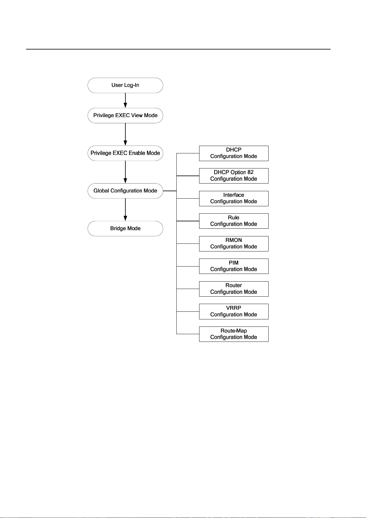
UMN:CLI User Manual
SURPASS hiD 6615 S223/S323 R1.5
Fig. 3.1 shows hiD 6615 S323 software mode structure briefly.
Fig. 3.1 Software mode structure
28 A50010-Y3-C150-2-7619
Page 29

User Manual UMN:CLI
SURPASS hiD 6615 S223/S323 R1.5
3.1.1 Privileged EXEC View Mode
When you log in to the switch, the CLI will start with Privileged EXEC View mode that is a
read-only mode. In this mode, you can see a system configuration and information with
several commands.
Tab. 3.1 shows main command of Privileged EXEC View mode.
Command Description
enable Opens Privileged EXEC Enable mode.
exit Logs out the switch.
show Shows a system configuration and information.
Tab. 3.1 Main Commands of Privileged EXEC View Mode
3.1.2 Privileged EXEC Enable Mode
To configure the switch, you need to open Privileged EXEC Enable mode with the enable
command, then the system prompt will changes from SWITCH> to SWITCH#.
Command Mode Description
enable View Opens Privileged EXEC Enable mode.
You can set a password to Privileged EXEC Enable mode to enhance security. Once set-
ting a password, you should enter a configured password, when you open Privileged
EXEC Enable mode.
Tab. 3.2 shows main commands of Privileged EXEC Enable mode.
Command Description
clock Inputs time and date in system.
configure terminal Opens Configuration mode.
telnet Connects to another device through telnet.
terminal length Configures the number of lines to be displayed in screen.
traceroute Traces transmission path of packet.
where Finds users accessed to system through telnet.
Tab. 3.2 Main Commands of Privileged EXEC Enable Mode
3.1.3 Global Configuration Mode
In Global Configuration mode, you can configure general functions of the system. You can
also open another configuration mode from this mode.
To open Global Configuration mode, enter the configure terminal command, and then
the system prompt will be changed from SWITCH# to SWITCH(config)#.
Command Mode Description
configure terminal Enable
Opens Global Configuration mode from Privileged
EXEC Enable mode.
A50010-Y3-C150-2-7619 29
Page 30

UMN:CLI User Manual
SURPASS hiD 6615 S223/S323 R1.5
Tab. 3.3 shows a couple of important main commands of Global Configuration mode.
Command Description
access-list Configures policy to limit routing information on the standard of AS.
arp Registers IP address and MAC address in ARP table.
bgp Helps BGP configuration.
bridge Opens Bridge Configuration mode.
copy Makes a backup file for the configuration of the switch.
dot1x Configures various functions of 802.1x daemon.
end Closes current mode and returns to User EXEC mode.
exit Closes current mode and returns to previous mode.
hostname Changes host name of the switch.
exec-timeout Configures auto-logout function.
fan Configures fan operation
interface Opens Interface Configuration mode.
ip Configures various functions of the interface.
passwd Changes a system password.
qos Configures QoS.
restore factory-defaults Restores the default configuration of the switch.
rmon-alarm Opens Rmon-alarm configuration mode.
rmon-event Opens Rmon-event configuration mode.
rmon-history Opens Rmon-history configuration mode.
route-map Opens Route-map Configuration mode.
router Opens Router Configuration mode.(OSPF. RIP, VRRP, PIM, BGP)
snmp Configures SNMP.
sntp Configures SNTP
syslog Configures syslog.
time-zone Configures time zone.
Tab. 3.3 Main Commands of Global Configuration Mode
3.1.4 Bridge Configuration Mode
In Bridge Configuration mode, you can configure various Layer 2 functions such as VLAN,
STP, LACP, EFM OAM, etc.
To open Bridge Configuration mode, enter the bridge command, then the system prompt
will be changed from SWITCH(config)# to SWITCH(bridge)#.
Command Mode Description
bridge Global Opens Bridge Configuration mode.
30 A50010-Y3-C150-2-7619
Page 31

User Manual UMN:CLI
SURPASS hiD 6615 S223/S323 R1.5
Tab. 3.4 shows a couple of main commands of Bridge Configuration mode.
Command Description
auto-reset
dhcp-server-filter
erp
lacp Configures LACP function.
lldp Configures LLDP function
mac Manages MAC address
mac-flood-guard Configures mac-flood-guard.
mirror Configures mirroring function.
oam Configures EFM-OAM protocol
port Sets port configuration
stp Configures Spanning Tree Protocol
trunk Configures trunk-function.
vlan Configures VLAN function.
Tab. 3.4 Main Commands of Bridge Configuration Mode
3.1.5 Rule Configuration Mode
You can open Rule Configuration mode using the command, rule NAME create, on
Global Configuration mode.
Configures the system for automatic rebooting
Configures packet filtering of DHCP server.
Configures ERP function
If you open Rule Configuration mode, the system prompt is changed from
SWITCH(config)# to SWITCH(config-rule[name])#.
Command Mode Description
rule NAME create Global Opens Rule Configuration mode.
On the Rule Configuration mode, it is possible to configure the condition and operational
method for the packets to which the rule function is applied.
Tab. 3.5 shows a couple of important main commands of Rule Configuration mode.
Command Description
apply Configures rule configuration and applies it to the switch.
mac Configures a packet condition by MAC address.
match Configures an operational condition which meets the packet condition.
port Configures a packet condition by port number.
priority Configures the priority for rule.
vlan Configures VLAN.
Tab. 3.5 Main Commands of Rule Configuration Mode
A50010-Y3-C150-2-7619 31
Page 32

UMN:CLI User Manual
SURPASS hiD 6615 S223/S323 R1.5
3.1.6 DHCP Configuration Mode
To open DHCP Configuration mode, use the command, ip dhcp pool POOL, on Global
Configuration mode as follow. Then the prompt is changed from SWITCH(config)# to
SWITCH(config-dhcp[POOL])#.
Command Mode Description
ip dhcp pool POOL Global Opens DHCP Configuration mode to configure DHCP.
DHCP Configuration mode is to configure range of IP address used in DHCP server,
group in subnet, and default gateway of subnet.
Command Description
default-router Configures a default gateway of subnet.
dns-server Configures DNS server.
range Configures a range of IP address used in DHCP server.
subnet Configures a subnet
Tab. 3.6 Main Commands of DHCP Configuration Mode
3.1.7 DHCP Option 82 Configuration Mode
To open DHCP Option 82 Configuration mode, use the command, ip dhcp option82, on
Global Configuration mode as follow. Then the prompt is changed from SWITCH(config)#
to SWITCH(config-opt82)#.
Command Mode Description
ip dhcp option82 Global
On DHCP Option 82 Configuration mode, configure a range of IP address used in DHCP
server and designate the group in subnet and configure default gateway of the subnet.
Tab. 3.7 is the main commands of DHCP Option 82 Configuration mode of hiD 6615
S223/S323.
Command Description
policy Configures a rule for option 82 packet.
remote-id Configures a remote ID.
system-remote-id Configures the remote ID of the system.
system-circuit-id Configures the circuit ID of the system.
Opens DHCP Option 82 Configuration mode for DHCP
option 82 configuration.
Tab. 3.7 Main Commands of DHCP Option 82 Configuration Mode
32 A50010-Y3-C150-2-7619
Page 33

User Manual UMN:CLI
SURPASS hiD 6615 S223/S323 R1.5
3.1.8 Interface Configuration Mode
To open Interface Configuration mode, enter the command, interface INTERFACE, on
Global Configuration mode, and then the prompt is changed from SWITCH(config)# to
SWITCH(config-if)#.
Command Mode Description
interface INTERFACE Global Opens Interface Configuration mode.
Interface Configuration mode is to assign IP address in Ethernet interface and to activate
or deactivate interface.
Tab. 3.8 shows a couple of main commands of Interface Configuration mode.
Command Description
bandwidth Configures bandwidth used to make routing information.
description Makes description of interface.
ip Assigns IP address.
shutdown Deactivates interface.
mtu Sets MTU value to interface.
Tab. 3.8 Main Commands of Interface Configuration Mode
3.1.9 RMON Configuration Mode
To open RMON-Alarm Configuration mode, enter rmon-alarm <1-65534>. To open
RMON-Event Configuration mode, input rmon-event <1-65534>. And to open RMONHistory Configuration mode, enter rmon-history <1-65534>.
Tab. 3.9 shows a couple of important main commands of RMON Configuration mode.
Command Description
active Enables each RMON configuration.
community Configures password for trap message transmission right.
description Describes the RMON event.
falling-event
falling-threshold Defines the falling threshold
owner
rising-event
requested-buckets Defines a bucket count for the interval.
Configures to generate RMON alarm when object is less than config-
ured threshold.
Shows the subject, which configures each RMON and uses related
information.
Configures to generate RMON alarm when object is more than config-
ured threshold.
Tab. 3.9 Main Commands of RMON Configuration Mode
A50010-Y3-C150-2-7619 33
Page 34

UMN:CLI User Manual
SURPASS hiD 6615 S223/S323 R1.5
3.1.10 Router Configuration Mode
To open Router Configuration mode, use the following command. The system prompt is
changed from SWITCH(config)# to SWITCH(config-router)#.
Command Mode Description
router IP-PROTOCOL Global Opens Router Configuration mode.
!
hiD 6615 S323. (Unavailable for hiD 6615 S223)
According to routing protocol way, Router Config uration mode is divided into BGP, RIP,
and OSPF. They are used to configure each IP routing protocol.
Tab. 3.10 shows a couple of main commands of Router Configuration mode.
Routing functionalities such as RIP, OSPF, BGP, VRRP and PIM-SM are only available for
Command Description
distance Configures distance value to find better route.
neighbor Configures neighbor router.
network Configures network to operate each routing protocol.
redistribute Registers transmitted routing information to another router’s table.
Tab. 3.10 Main Commands of Router Configuration Mode
3.1.11 VRRP Configuration Mode
To open VRRP Configuration mode, use the following command. The system prompt is
changed from SWITCH(config)# to SWITCH(config-router)#.
Command Mode Description
router vrrp INTERFACE GROUP-
ID
Global Opens VRRP Configuration mode.
Tab. 3.11 shows a couple of main commands of Router Configuration mode.
Command Description
associate Configures associated IP address same with virtual router.
authentication Configures password of virtual router group.
preempt Activates/deactivates preempt.
track Configures VRRP track.
vip-access Configures the function of accessing associated IP address.
vr-priority Assigns priority to virtual router.
vr-timers
Configures advertisement time, which means the interval that master
router distributes its information to another virtual router.
Tab. 3.11 Main Commands of VRRP Configuration Mode
34 A50010-Y3-C150-2-7619
Page 35

User Manual UMN:CLI
SURPASS hiD 6615 S223/S323 R1.5
3.1.12 Route-Map Configuration Mode
To open Route-map Configuration mode, use the following command. The prompt is
changed from SWITCH(config)# to SWITCH(config-route-map)#.
Command Mode Description
route-map NAME {permit | deny}
<1-65535>
On Route-map Configuration mode, you can configure the place where information is
from and sent in routing table.
Tab. 3.12 shows a couple of important main commands of Route-map Configuration
mode.
Command Description
match Transmits routing information to specified place.
set Configures router address and distance.
Global Opens Route-map Configuration mode.
Tab. 3.12 Main Commands of Route-map Configuration Mode
A50010-Y3-C150-2-7619 35
Page 36

UMN:CLI User Manual
SURPASS hiD 6615 S223/S323 R1.5
3.2 Useful Tips
This section provides useful functions for user’s convenience while using CLI commands.
They are as follow.
•
Listing Available Commands
•
Calling Command History
•
Using Abbreviation
•
Using Command of Privileged EXEC Enable Mode
•
Exit Current Command Mode
3.2.1 Listing Available Commands
To list available commands, input question mark <?>. When you input the question mark
<?> in each command mode, you can see available commands used in this mode and
variables following after the commands.
The following is the available commands on Privileged EXEC Enable mode of the hiD
6615 S223/S323.
SWITCH# ?
Exec commands:
clear Reset functions
clock Manually set the system clock
configure Enter configuration mode
copy Copy from one file to another
debug Debugging functions (see also 'undebug')
disconnect Disconnect user connection
enable Turn on privileged mode command
erase Erase saved configuration
exit End current mode and down to previous mode
halt Halt process
help Description of the interactive help system
no Negate a command or set its defaults
ping Send echo messages
quote Execute external command
rcommand Management stacking node
release Release the acquired address of the interface
reload Reload the system
renew Re-acquire an address for the interface
restore Restore configurations
show Show running system information
ssh Configure secure shell
tech-support Technical Supporting Function for Diagnosis System
(ommitted)
SWITCH#
i
<ENTER> key to display commands list.
If you need to find out the list of available commands of the current mode in detail, use
the following command.
36 A50010-Y3-C150-2-7619
Question mark <?> will not be seen in the screen and you do not need to press
Page 37

User Manual UMN:CLI
SURPASS hiD 6615 S223/S323 R1.5
Command Mode Description
show list Shows available commands of the current mode.
show cli
All
Shows available commands of the current mode with
tree structure.
The following is an example of displaying list of available commands of Privileged EXEC
Enable mode.
SWITCH# show list
clear arp
clear arp IFNAME
clear ip bgp *
clear ip bgp * in
clear ip bgp * in prefix-filter
clear ip bgp * ipv4 (unicast|multicast) in
clear ip bgp * ipv4 (unicast|multicast) in prefix-filter
clear ip bgp * ipv4 (unicast|multicast) out
clear ip bgp * ipv4 (unicast|multicast) soft
clear ip bgp * ipv4 (unicast|multicast) soft in
clear ip bgp * ipv4 (unicast|multicast) soft out
-- more –
i
In case of the hiD 6615 S223/S323 installed command shell, you can find out commands
starting with specific alphabet. Input the first letter and question mark without space. The
following is an example of finding out the commands starting “s” in Privileged EXEC En-
able mode of hiD 6615 S223/S323.
Press the <ENTER> key to skip to the next list.
SWITCH# s ?
show Show running system information
ssh Configure secure shell
SWITCH# s
Also, it is possible to view variables you should input following after commands. After inputting the command you need, make one space and input question mark. The following
is an example of viewing variables after the command, write. Please note that you must
make one space after inputting.
SWITCH# write ?
memory Write to NV memory
terminal Write to terminal
SWITCH# write
3.2.2 Calling Command History
In case of installed command shell, you do not have to enter repeated command again.
When you need to call command history, use this arrow key <↑>. When you press the arrow key, the latest command you used will be displayed one by one.
The following is an example of calling command history after using several commands.
A50010-Y3-C150-2-7619 37
Page 38

UMN:CLI User Manual
SURPASS hiD 6615 S223/S323 R1.5
After using these commands in order: show clock → configure terminal → interface 1
→ exit, press the arrow key <↑> and then you will see the commands from latest one:
exit → interface 1 → configure terminal → show clock.
SWITCHconfig)# exit
SWITCH# show clock
Mon, 5 Jan 1970 23:50:12 GMT+0000
SWITCH# configure terminal
SWITCH(config)# interface 1
SWITCH(config-if)# exit
SWITCH(config)# exit
SWITCH# (press the arow key ↑)
↓
SWITCH# exit (arrow key ↑)
↓
SWITCH# interface 1 (arrow key ↑)
↓
SWITCH# configure terminal (arrow key ↑)
↓
SWITCH# show clock (arrow key ↑)
The hiD 6615 S223/S323 also provides the command that shows the commands used
before up to 100 lines.
Command Mode Description
show history Enable Shows a command history.
3.2.3 Using Abbreviation
Most of the commands can be used also with abbreviated form. The following table
shows some examples of abbreviated commands.
Command Abbreviation
clock cl
exit ex
show sh
configure terminal con te
Tab. 3.13 Command Abbreviation
3.2.4 Using Command of Privileged EXEC Enable Mode
You can execute the commands of Privileged EXEC Enable mode as show, ping, telnet,
traceroute, and so on regardless of which mode you are located on.
To execute the commands of Privileged EXEC Enable mode on another mode, use the
following command.
Command Mode Description
do COMMAND All Executes the commands of Privileged EXEC mode.
38 A50010-Y3-C150-2-7619
Page 39

User Manual UMN:CLI
SURPASS hiD 6615 S223/S323 R1.5
3.2.5 Exit Current Command Mode
To exit to the previous command mode, use the following command.
Command Mode Description
exit Exits to the previous command mode.
end
If you use the command, exit, on Privileged EXEC View mode or Privileged EXEC En-
!
able mode, you will be logged out!
All
Exits to Privileged EXEC enable mode.
A50010-Y3-C150-2-7619 39
Page 40

UMN:CLI User Manual
SURPASS hiD 6615 S223/S323 R1.5
4 System Connection and IP Address
4.1 System Connection
After installing switch, the hiD 6615 S223/S323 is supposed to examine that each port is
rightly connected to network and management PC. And then, user connects to system to
configure and manage the hiD 6615 S223/S323. This section provides instructions how to
change password for system connection, connect to system through telnet as the following order.
•
System Login
•
Password for Privileged EXEC Mode
•
Changing Login Password
•
Management for System Account
•
Limiting Number of User
•
Telnet Access
•
Auto Log-out
•
System Rebooting
4.1.1 System Login
After installing the hiD 6615 S223/S323, finally make sure that each port is correctly connected to PC for network and management. And then, turn on the power and boot the
system as follow.
Step 1
When you turn on the switch, booting will be automatically started and login prompt will
be displayed.
SWITCH login:
Step 2
When you enter login ID at the login prompt, password prompt will be displayed. And en-
ter password to open Privileged EXEC View mode. By default setting, login ID is config-
ured as admin and it is possible to access without password.
SWITCH login: admin
Password:
SWITCH>
Step 3
In Privileged EXEC View mode, you can check only the configuration for the switch. To
configure and manage the switch, you should begin Privileged EXEC Enable mode. The
following is an example of beginning Privileged EXEC Enable mode.
SWITCH> enable
SWITCH#
40 A50010-Y3-C150-2-7619
Page 41

User Manual UMN:CLI
SURPASS hiD 6615 S223/S323 R1.5
4.1.2 Password for Privileged EXEC Mode
You can configure a password to enhance the security for Privileged EXEC Enable mode.
To configure a password for Privileged EXEC Enable mode, use the following command.
Command Mode Description
passwd enable PASSWORD
passwd enable 8 PASSWORD
Global
password enable does not support encryption at default value. Therefore, it shows the
!
string (or password) as it is when you use the show running-config command. In this
case, the user’s password shown to everyone and has insecure environment.
To encrypt the password which will be shown at running-config, you should use the ser-
vice password-encryption command. And to represent the string (password) is encrypted, input 8 before the encrypted string.
When you use the password enable command with 8 and “the string”, you will make into
Privileged EXEC Enable mode with the encrypted string. Therefore, to log in the system,
you should do it with the encrypted string as password that you configured after 8. In
short, according to using the 8 option or not, the next string is encrypted or not.
Configures a password to begin Privileged EXEC En-
able mode.
Configures an encrypted password.
The following is an example of configure the password in Privileged EXEC Enable mode
as testpassword.
SWITCH# configure terminal
SWITCH(config)# passwd enable testpassword
SWITCH(config)#
The following is an example of accessing after configuring the password.
SWITCH login: admin
Password:
SWITCH > enable
Password:
SWITCH#
To delete the configured password, use the following command.
Command Mode Description
no passwd enable Global Deletes the password.
The created password can be displayed with the command, show running-config. To
encrypt the password not to be displayed, use the following command.
Command Mode Description
service password-encryption Global Encrypts system password.
A50010-Y3-C150-2-7619 41
Page 42

UMN:CLI User Manual
SURPASS hiD 6615 S223/S323 R1.5
To disable password encryption, use the following command.
Command Mode Description
no service password-encryption Global Disables password encryption.
4.1.3 Changing Login Password
To configure a password for created account, use the following command.
Command Mode Description
passwd [NAME] Global Configures a password for created account.
The following is an example of changing password.
SWITCH(config)# passwd Siemens
Changing password for Siemens
Enter the new password (minimum of 5, maximum of 8 characters)
Please use a combination of upper and lower case letters and numbers.
Enter new password:junior95
Re-enter new password:junior95
Password changed.
SWITCH(config)#
The password you are entering won’t be seen in the screen, so please be careful not to
!
make mistake.
4.1.4 Management for System Account
4.1.4.1 Creating System Account
For the hiD 6615 S223/S323, the administrator can create a system account. In addition,
it is possible to set the security level from 0 to 15 to enhance the system security.
To create a system account, use the following command.
Command Mode Description
user add NAME DESCRIPTION Creates a system account.
user add NAME le vel <0-15>
DESCRIPTION
The account of level 0 to level 14 without any configuring authority only can use exit and
i
help in Privileged EXEC View mode and cannot access to Privileged EXEC Enable mode.
The account with the highest level 15 has a read-write authority.
Global
Creates a system account with a security level.
42 A50010-Y3-C150-2-7619
Page 43

User Manual UMN:CLI
-
-
SURPASS hiD 6615 S223/S323 R1.5
To delete the created account, use the following command.
Command Mode Description
user del NAME Global Delete the created account.
To display the created account, use the following command.
Command Mode Description
show user Enable/Global Shows the created account.
4.1.4.2 Configuring Security Level
For the hiD 6615 S223/S323, it is possible to configure the security level from 0 to 15 for
a system account. The level 15, as the highest level, has a read-write authority. The administrator can configure from level 0 to level 14. The administrator decides which level
user uses which commands in which level. As the basic right from level 0 to level 14, it is
possible to use exit and help command in Privileged EXEC Enable mode and it is not
possible to access to Privileged EXEC Enable mode.
To define the security level and its authority, use the following command.
Command Mode Description
privilege bgp level <0-15>
{COMMAND | all}
privilege bridge level <0-15>
{COMMAND | all}
privilege configure level <0-15>
{COMMAND | all}
privilege dhcp-option82 level
<0-15> {COMMAND | all}
privilege dhcp-pool level <0-15>
{COMMAND | all}
privilege dhcp-class level
<0-15> {COMMAND | all}
Global
privilege dhcp-pool-class level
<0-15> {COMMAND | all}
privilege enable level <0-15>
{COMMAND | all}
privilege interface level <0-15>
{COMMAND | all}
Uses the specific command of BGP Configuration mode
in the level.
Uses the specific command of Bridge Configuration
mode in the level.
Uses the specific command of Global Configuration
mode in the level.
Uses the specific command of DHCP Option 82 Con
figuration mode in the level.
Uses the specific command of DHCP Configuration
mode in the level.
Uses the specific command of DHCP Option 82 Con
figuration mode in the level.
Uses the specific command of DHCP Configuration
mode in the level.
Uses the specific command of Privileged EXEC mode
in the level.
Uses the specific command of Interface Configuration
mode in the level.
privilege ospf level <0-15>
{COMMAND | all}
privilege pim level <0-15>
{COMMAND | all}
privilege rip level <0-15>
{COMMAND | all}
Uses the specific command of OSPF Configuration
mode in the level.
Uses the specific command of PIM Configuration mode
in the level.
Uses the specific command of RIP Configuration mode
in the level.
A50010-Y3-C150-2-7619 43
Page 44

UMN:CLI User Manual
-
SURPASS hiD 6615 S223/S323 R1.5
Command Mode Description
privilege rmon-alarm level
<0-15> {COMMAND | all}
privilege rmon-event level
<0-15> {COMMAND | all}
Uses the specific command of RMON Configuration
mode in the level.
privilege rmon-history level
<0-15> {COMMAND | all}
privilege route-map level
<0-15> {COMMAND | all}
privilege rule level <0-15>
{COMMAND | all}
privilege view level <0-15>
{COMMAND | all}
privilege vrrp level <0-15>
{COMMAND | all}
Global
Uses the specific command of RMON Configuration
mode in the level.
Uses the specific command of Route-map Configura
tion mode in the level.
Uses the specific command of Rule Configuration mode
in the level.
Uses the specific command of User EXEC mode in the
level.
Uses the specific command of VRRP Configuration
mode in the level.
The commands that are used in low level can be also used in the higher level. For example, the command in level 0 can be used in from level 0 to level 14.
The commands should be input same as the displayed commands by show list. There-
fore, it is not possible to input the commands in the bracket separately.
SWITCH# show list
clear arp-inspection mapping counter
clear arp-inspection statistics
clear cpu statistics (PORTS|)
clear ip bgp *
clear ip bgp * in
clear ip bgp * in prefix-filter
clear ip bgp * ipv4 (unicast|multicast) in
clear ip bgp * ipv4 (unicast|multicast) in prefix-filter
clear ip bgp * ipv4 (unicast|multicast) out
clear ip bgp * ipv4 (unicast|multicast) soft
clear ip bgp * ipv4 (unicast|multicast) soft in
clear ip bgp * ipv4 (unicast|multicast) soft out
clear ip bgp * out
clear ip bgp * soft
clear ip bgp * soft in
clear ip bgp * soft out
clear ip bgp * vpnv4 unicast in
clear ip bgp * vpnv4 unicast out
--More-(Omitted)
It is not possible to input clear ip bgp * ipv4 unicast in. You should input like clear ip
bgp * ipv4 {unicast | multicast} in.
The commands starting with the same character are applied by inputting only the starting
commands. For example, if you input show, all the commands starting with show are
applied.
44 A50010-Y3-C150-2-7619
Page 45

User Manual UMN:CLI
SURPASS hiD 6615 S223/S323 R1.5
To delete a configured security level, use the following command.
Command Mode Description
no privilege Deletes all configured security levels.
no privilege bgp level <0-15>
{COMMAND | all}
no privilege bridge level <0-15>
{COMMAND | all}
no privilege configure level
<0-15> {COMMAND | all}
no privilege dhcp-option82 level
<0-15> {COMMAND | all}
no privilege dhcp-pool level
<0-15> {COMMAND | all}
no privilege dhcp-class level
<0-15> {COMMAND | all}
no privilege dhcp-pool-class
level <0-15> {COMMAND | all}
no privilege enable level <0-15>
{COMMAND | all}
no privilege interface level
<0-15> {COMMAND | all}
no privilege ospf level <0-15>
{COMMAND | all}
no privilege pim level <0-15>
{COMMAND | all}
no privilege rip level <0-15>
{COMMAND | all}
no privilege rmon-alarm level
<0-15> {COMMAND | all}
no privilege rmon-event level
<0-15> {COMMAND | all}
no privilege rmon-history level
<0-15> {COMMAND | all}
no privilege route-map level
<0-15> {COMMAND | all}
Global
Delete a configured security level on each mode.
no privilege rule level <0-15>
{COMMAND | all}
no privilege view level <0-15>
{COMMAND | all}
no privilege vrrp level <0-15>
{COMMAND | all}
A50010-Y3-C150-2-7619 45
Page 46

UMN:CLI User Manual
SURPASS hiD 6615 S223/S323 R1.5
To display a configured security level, use the following command.
Command Mode Description
show privilege Shows a configured security level.
show privilege now
View
Enable
Global
Shows a security level of current mode.
The following is an example of creating the system account test0 having a security level
10 and test1 having a security level 1 without password.
SWITCH(config)# user add test0 level 0 level0user
Changing password for test0
Enter the new password (minimum of 5, maximum of 8 characters)
Please use a combination of upper and lower case letters and numbers.
Enter new password:(Enter)
Bad password: too short.
Warning: weak password (continuing).
Re-enter new password: (Enter)
Password changed.
SWITCH(config)# user add test1 level 1 level1user
Changing password for test1
Enter the new password (minimum of 5, maximum of 8 characters)
Please use a combination of upper and lower case letters and numbers.
Enter new password: (Enter)
Bad password: too short.
Warning: weak password (continuing).
Re-enter new password: (Enter)
Password changed.
SWITCH(config)# show user
====================================================
User name Description Level
====================================================
test0 level0user 0
test1 level1user 1
SWITCH(config)#
The following is an example of configuring an authority of the security level 0 and 1.
SWITCH(config)# privilege view level 0 enable
SWITCH(config)# privilege enable level 0 show
SWITCH(config)# privilege enable level 1 configure terminal
SWITCH(config)# show privilege
Command Privilege Level Configuration
---------------------------------------------- Node All Level Command
EXEC(ENABLE) 1 configure terminal
EXEC(VIEW) 0 enable
EXEC(ENABLE) 0 show
3 entry(s) found.
SWITCH(config)#
In the above configuration, as level 0, it is possible to use only show command in Privi-
46 A50010-Y3-C150-2-7619
Page 47

User Manual UMN:CLI
SURPASS hiD 6615 S223/S323 R1.5
leged EXEC Enable mode; however as level 1, it is possible to use not only the commands in level 1 but also time configuration commands in Privileged EXEC Enable mode
and accessing commands to Global Configuration mode.
4.1.5 Limiting Number of User
For hiD 6615 S223/S323, you can limit the number of user accessing the switch through
both console port and telnet. In case of using the system authentication with RADIUS or
TACACS+, the configured number includes the number of user accessing the switch via
the authentication server.
To set the number of user accessing the switch, use the following command.
Command Mode Description
login connect <1-8> Global
Sets the number of user accessing the switch.
Default: 8
4.1.6 Telnet Access
To connect to the host through telnet at remote place, use the following command.
Command Mode Description
telnet DESTINATION [TCP-PORT] Enable
Connects to a remote host.
DESTINATION: IP address or host name
In case of telnet connection, you should wait for [OK] message, when you save a system
!
configuration. Otherwise, all changes will be deleted when the telnet session is disconnected.
SWITCH# write memory
[OK]
SWITCH#
The system administrator can disconnect users connected from remote place. To disconnect a user connected through telnet, use the following command.
Command Mode Description
disconnect TTY-NUMBER Enable Disconnects a user connected through telnet.
The following is an example of disconnecting a user connected from a remote place.
SWITCH# where
admin at from console for 4 days 22 hours 15 minutes 24.88 seconds
admin at ttyp0 from 10.0.1.4:1670 for 4 days 17 hours 53 minutes 28.76 seconds
admin at ttyp1 from 147.54.140.133:49538 for 6 minutes 34.12 seconds
SWITCH# disconnect ttyp0
SWITCH# where
admin at from console for 4 days 22 hours 15 minutes 34.88 seconds
admin at ttyp1 from 147.54.140.133:49538 for 6 minutes 44.12 seconds
SWITCH#
A50010-Y3-C150-2-7619 47
Page 48

UMN:CLI User Manual
SURPASS hiD 6615 S223/S323 R1.5
4.1.7 Auto Log-out
For security reasons of the hiD 6615 S223/S323, if no command is entered within the
configured inactivity time, the user is automatically logged out of the system. Administrator can configure the inactivity timer.
To enable auto-logout function, use the following command.
Command Mode Description
Enables auto log-out.
exec-timeout <1-35791> [<0-59>]
exec-timeout 0
Global
To display a configuration of auto-logout function, use the following command.
Command Mode Description
show exec-timeout
Enable
Global
1-35791: time unit in minutes (by default 10 minutes)
0-59: time unit in seconds
Disables auto log-out.
Shows a configuration of auto-logout function.
The following is an example of configuring auto-logout function as 60 seconds and viewing the configuration.
SWITCH(config)# exec-timeout 60
SWITCH(config)# show exec-timeout
Log-out time : 60 seconds
SWITCH(config)#
4.1.8 System Rebooting
4.1.8.1 Manual System Rebooting
When installing or maintaining the system, some tasks require rebooting the system by
various reasons. Then you can reboot the system with a selected system OS.
To restart the system manually, use the following command.
Command Mode Description
reload [os1 | os2] Enable Restarts the system.
If you reboot the system without saving new configuration, new configuration will be deleted. So, you have to save the configuration before rebooting. Not to make that mistake,
hiD 6615 S223/S323 is supported to print the following message to ask if user really
wants to reboot and save configuration.
If you want to continue to reboot, press <y> key, if you want to save new configuration,
press <n> key.
SWITCH# reload
Do you want to save the system configuration? [y/n]]
48 A50010-Y3-C150-2-7619
Page 49

User Manual UMN:CLI
SURPASS hiD 6615 S223/S323 R1.5
4.1.8.2 Auto System Rebooting
The hiD 6615 S223/S323 reboots the system according to user’s configuration. There are
two basises for system rebooting. These are CPU and memory. CPU is rebooted in case
CPU Load or Interrupt Load continues for the configured time. Memory is automatically
rebooted in case memory low occurs as the configured times.
To enable auto system rebooting function, use the following command.
Command Mode Description
Configure to reboot the system automatically in case
an average of CPU or interrupt load exceeds the con-
auto-reset cpu <50-100> <1-100>
TIME
Bridge
auto-reset memory <1-120> <1-
10>
no auto-reset {cpu | memory}
figured value during the user-defined time.
50-100: average of CPU load per 1 minute
1-100: average of interrupt load
TIME: minute
Configure to reboot the system automatically in case
memory low occurs as the configured value.
1-120: time of memory low
1-10: count of memory low(The default is 5)
Disables auto system rebooting.
To show auto system rebooting configuration, use the following command.
Command Mode Description
show auto-reset {cpu | memory}
Global/
Bridge
The following is an example of configuring auto-restarting function in case CPU load or
Interrupt load maintains over 70% during 60 seconds and viewing the configuration.
SWITCH(config)# SWITCH(bridge)# auto-reset cpu 70 70 1
SWITCH(bridge)# show auto-reset cpu
----------------------------- Auto-Reset Configuration(CPU)
-----------------------------auto-reset: on
cpu load: 70
interrupt load: 70
continuation time: 1
SWITCH(bridge)#
4.2 System Authentication
Shows a configuration of auto-rebooting function.
For the enhanced system security, the hiD 6615 S223/S323 provides two authentication
methods to access the switch using Remote Authentication Dial-In User Service (RADIUS) and Terminal Access Controller Access Control System Plus (TACACS+).
A50010-Y3-C150-2-7619 49
Page 50

UMN:CLI User Manual
SURPASS hiD 6615 S223/S323 R1.5
4.2.1 Authentication Method
To set the system authentication method, use the following command.
Command Mode Description
Set the system authentication method.
local: authentication for console access
login {local | remote} {radius |
tacacs | host | all} enable
login {local | remote} {radius |
tacacs | host | all} disable
Global
remote: authentication for telnet access
radius: selects RADIUS authentication.
tacacs: selects TACACS+ authentication.
host: selects nominal system authentication (default).
all: selects all the authentication methods.
Disables a configured system authentication method.
4.2.2 Authentication Interface
If more than 2 interfaces are specified to the hiD 6615 S223/S323, you can designate one
specific interface to access RADIUS or TACACS server.
To designate an authentication interface, use the following command.
Command Mode Description
login {radius | tacacs} interface
INTERFACE [A.B.C.D]
Global
4.2.3 Primary Authentication Method
You can set the order of the authentication method with giving the priority to each authentication method. To set the primary authentication method, use the following command
Command Mode Description
login {local | remote} {radius |
tacacs | host} primary
Global
Designates an authentication interface.
radius: selects RADIUS authentication.
tacacs: selects TACACS+ authentication.
INTERFACE: interface name
A.B.C.D: IP address (optional)
Set the primary authentication method.
local: authentication for console access
remote: authentication for telnet access
radius: selects RADIUS authentication.
tacacs: selects TACACS+ authentication.
host: selects nominal system authentication (default).
50 A50010-Y3-C150-2-7619
Page 51

User Manual UMN:CLI
SURPASS hiD 6615 S223/S323 R1.5
4.2.4 RADIUS Server
4.2.4.1 RADIUS Server for System Authentication
To add/delete the RADIUS server for system authentication, use the following command.
Command Mode Description
login radius server A.B.C.D
KEY
login radius server A.B.C.D
KEY auth_port PORT acct_port
PORT
no login radius server A.B.C.D
Global
Adds the RADIUS server with its information.
A.B.C.D: RADIUS server address
KEY: authentication key value
Adds the RADIUS server with its information.
A.B.C.D: RADIUS server address
KEY: authentication key value
auth_port: Enters authentication port number(optional)
acct_port: Enters accounting port number(optional)
Deletes an added RADIUS server.
i
4.2.4.2 RADIUS Server Priority
You can add up to 5 RADIUS servers.
To specify the priority of a registered RADIUS server, use the following command.
Command Mode Description
login radius server move
A.B.C.D <1-5>
Global
4.2.4.3 Timeout of Authentication Request
After the authentication request, the hiD 6615 S223/S323 waits for the response from the
RADIUS server for specified time.
To specify a timeout value, use the following command.
Command Mode Description
login radius timeout <1-100> Global
Specifies the priority of RADIUS server.
A.B.C.D: IP address
1-5: priority of RADIUS server
Specifies a timeout value.
1-100: waiting-time for the response (default: 3)
A50010-Y3-C150-2-7619 51
Page 52

UMN:CLI User Manual
SURPASS hiD 6615 S223/S323 R1.5
4.2.4.4 Frequency of Retransmit
If there is no response from RADIUS server, the hiD 6615 S223/S323 is supposed to retransmit an authentication request. To set the frequency of retransmitting an authentication request, use the following command.
Command Mode Description
login radius retransmit <1-10> Global
Sets the frequency of retransmit.
1-10: Enters the times of retry (default: 3)
4.2.5 TACACS Server
4.2.5.1 TACACS Server for System Authentication
To add/delete the TACACS server for system authentication, use the following command.
Command Mode Description
Adds the TACACS server with its information.
login tacacs server A.B.C.D KEY
Global
no login tacacs server A.B.C.D
A.B.C.D: IP address
KEY: authentication key value
Deletes an added TACACS server.
A.B.C.D: IP address
i
After adding the TACACS server, you should register interface of TACACS server connected to user’s switch. Use the following command.
You can add up to 5 TACACS servers.
Command Mode Description
login tacacs interface NAME
A.B.C.D
no login tacacs interface
Global
4.2.5.2 TACACS Server Priority
To specify the priority of a registered TACACS server, use the following command.
Command Mode Description
login tacacs server move
A.B.C.D <1-5>
Global
4.2.5.3 Timeout of Authentication Request
Registers interface of TACACS server connected to
user’s switch.
Clears TACACS server interface
Specifies the priority of RADIUS server.
A.B.C.D: TACACS server address
1-5: the priority of TACACS server
After the authentication request, the hiD 6615 S223/S323 waits for the response from the
TACACS server for specified time.
52 A50010-Y3-C150-2-7619
Page 53

User Manual UMN:CLI
SURPASS hiD 6615 S223/S323 R1.5
To specify a timeout value, use the following command.
Command Mode Description
login tacacs timeout <1-100> Global
Specifies a timeout value.
1-100: waiting-time for the response (default: 3)
4.2.5.4 Additional TACACS+ Configuration
The hiD 6615 S223/S323 provides several additional options to configure the system authentication via TACACS server.
TCP Port for the Authentication
To specify TCP port for the system authentication, use the following command.
Command Mode Description
login tacacs socket-port
<1-65535>
no login tacacs socket-port
Global
Specifies TCP port for the authentication.
1-65535: TCP port
Deleted the configured TCP port for the authentication
Authentication Type
To select the authentication type for TACACS+, use the following command.
Command Mode Description
Selects the authentication type for TACACS+.
login tacacs auth-type {ascii |
pap | chap}
no login tacacs auth-type
Global
ascii: plain text
pap: password authentication protocol
chap: challenge handshake authentication protocol
Deletes a specified authentication type.
Priority Level
You can define a priority level of user. According to the defined priority level, the user has
different authorization to access the DSLAM. This priority must define in the TACACS
server in the same way.
To define the priority level of user, use the following command.
Command Mode Description
login tacacs priority-level {min |
user | max | root}
no login tacacs priority-level
Global
Defines the priority level of user, refer the below infor-
mation for the order of priority.
Deletes a defined priority level.
i
The order of priority is root = max > user > min.
A50010-Y3-C150-2-7619 53
Page 54

UMN:CLI User Manual
SURPASS hiD 6615 S223/S323 R1.5
4.2.6 Accounting Mode
The hiD 6615 S223/S323 provides the accounting function of AAA (Authentication, Authorization, and Accounting). Accounting is the process of measuring the resources a user
has consumed. Typically, accounting measures the amount of system time a user has
used or the amount of data a user has sent and received.
To set an accounting mode, use the following command.
Command Mode Description
Sets an accounting mode.
login accounting-mode {none |
start | stop | both}
Global
none: disables an accounting function.
start: measures start point only.
stop: measures stop point only.
both: measures start and stop point both.
4.2.7 Displaying System Authentication
To display a configured system authentication, use the following command.
show login
Command Mode Description
Enable
Global
Shows a configured system authentication.
54 A50010-Y3-C150-2-7619
Page 55

User Manual UMN:CLI
SURPASS hiD 6615 S223/S323 R1.5
4.2.8 Sample Configuration
[Sample Configuration 1] Configuration RADIUS server
The following is an example of configuring authorization method in SURPASS hiD 6615. It
is configured to add RADIUS to default method in case of clients connecting through console and telnet. And, the priority is given to RADIUS in case of clients connecting through
console and to default method in case of clients connecting through telnet.
Then, show the configuration. And The following is an example of configuring frequency
of retransmit and timeout of response after registering RADIUS server.
SWITCH(config)# user add user test1
Changing password for user
Enter the new password (minimum of 5, maximum of 8 characters)
Please use a combination of upper and lower case letters and numbers.
Enter new password:vertex
Re-enter new password:vertex
Password changed.
SWITCH(config)# login local radius enable
SWITCH(config)# login remote radius enable
SWITCH(config)# login local radius primary
SWITCH(config)# login remote host primary
SWITCH(config)# login radius server add 100.1.1.1 1
SWITCH(config)# login radius retransmit 5
SWITCH(config)# login radius timeout 10
SWITCH(config)# show login
[AUTHEN]
Local login : radius host
Remote login : host radius
Accounting mode : both
-----------------------------------[HOST]
maximum_login_counts : 8
-----------------------------------[RADIUS]
<Radius Servers & Key>
100.1.1.1 1
Radius Retries : 5
Radius Timeout : 10
Radius Interface : default
-----------------------------------[TACACS]
<Tacacs Servers & Key>
Tacacs Timeout : 3
Tacacs Socket Port : 49
Tacacs Interface : default
Tacacs PPP Id : 1
Tacacs Authen Type : ASCII
Tacacs Priority Level : MIN
SWITCH(config)#
Displayed according to priority.
A50010-Y3-C150-2-7619 55
Page 56

UMN:CLI User Manual
SURPASS hiD 6615 S223/S323 R1.5
[Sample Configuration 2] Configuration TACACS+ server
The following is an example of configuring authorization method as TACACS+.
SWITCH(config)# user add user test1
Changing password for user
Enter the new password (minimum of 5, maximum of 8 characters)
Please use a combination of upper and lower case letters and numbers.
Enter new password:vertex
Re-enter new password:vertex
Password changed.
SWITCH(config)# login local tacacs enable
SWITCH(config)# login remote tacacs enable
SWITCH(config)# login local tacacs primary
SWITCH(config)# login remote tacacs primary
SWITCH(config)# login tacacs server add 200.1.1.1 1
SWITCH(config)# login tacacs interface default
SWITCH(config)# login tacacs socket-port 1
SWITCH(config)# login tacacs auth-type pap
SWITCH(config)# login tacacs timeout 10
SWITCH(config)# login tacacs priority-level root
SWITCH(config)# show login
[AUTHEN]
Local login : tacacs host
Remote login : tacacs host
Accounting mode : both
-----------------------------------[HOST]
maximum_login_counts : 8
-----------------------------------[RADIUS]
<Radius Servers & Key>
Radius Retries : 3
Radius Timeout : 3
Radius Interface : default
-----------------------------------[TACACS]
<Tacacs Servers & Key>
200.1.1.1 1
Tacacs Timeout : 10
Tacacs Socket Port : 1
Tacacs Interface : default
Tacacs PPP Id : 1
Tacacs Authen Type : PAP
Tacacs Priority Level : MAX(ROOT)
SWITCH(config)#
Displayed according to the priority
4.3 Assigning IP Address
The switch uses only the data’s MAC address to determine where traffic needs to come
from and which ports should receive the data. Switches do not need IP addresses to
transmit packets. However, if you want to access to the hiD 6615 S223/S323 from remote
56 A50010-Y3-C150-2-7619
Page 57

User Manual UMN:CLI
SURPASS hiD 6615 S223/S323 R1.5
place with TCP/IP through SNMP or telnet, it requires IP address.
You can enable interface to communicate with switch interface on network and assign IP
address as the following:
•
Enabling Interface
•
Disabling Interface
•
Assigning IP Address to Network Interface
•
Static Route and Default Gateway
•
Displaying Forwarding Information Base(FIB) Table
•
Forwarding Information Base(FIB) Retain
•
Displaying Interface
•
Sample Configuration
4.3.1 Enabling Interface
To assign an IP address to an interface, you need to enable the interface first. If the interface is not enabled, you cannot access it from a remote place, even though an IP address
has been assigned.
To display if interface is enabled, use the command, show running-config.
Interface Configuration Mode
To open Interface Configuration mode of the interface you are about to enable interface,
use the following command.
Command Mode Description
interface INTERFACE Global Opens Interface Configuration mode of the interface.
To enable the interface, use the following command.
Command Mode Description
no shutdown Interface Enables the interface on Interface Configuration mode.
The following is an example of enabling interface on Interface Configuration mode.
SWITCH# configure terminal
SWITCH(config)# interface 1
SWITCH(config-if)# no shutdown
SWITCH(config-if)#
4.3.2 Disabling Interface
To disable the interface, use the following commands on Interface Configuration mode.
Before disabling interface on Interface Configuration mode, you should open the mode,
and then use the follow command.
Command Mode Description
shutdown Interface Disables an interface on Interface Configuration mode.
A50010-Y3-C150-2-7619 57
Page 58

UMN:CLI User Manual
SURPASS hiD 6615 S223/S323 R1.5
4.3.3 Assigning IP Address to Network Interface
After enabling interface, you need to assign IP address. To assign IP address to specified
network interface, use the following command.
Command Mode Description
ip address IP-ADDRESS/M Assigns IP address to an interface.
ip address IP-ADDRESS/M secondary
Interface
To disable the assigned IP address, use the following command.
Command Mode Description
no ip address IP-ADDRESS/M Removes assigned IP address to an interface.
no ip address IP-ADDRESS/M
secondary
Interface
Removes assigned secondary IP address to an inter-
face.
To display an assigned IP address, use the following command.
Assigns secondary IP address to an
interface.
Command Mode Description
show ip Interface Shows an assigned IP address of the interface.
4.3.4 Static Route and Default Gateway
It is possible to configure the static route. Static route is a route which user configures
manually. Packets are transmitted to the destination through static route. Static route includes destination address, neighbor router to receive packet, the number of routes that
packets have to go through.
To configure static route, use the following command.
Command Mode Description
ip route A.B.C.D SUBNET-MASK
{GATEWAY | null} [<1-255>]
ip route A.B.C.D/M { SUBNET-MASK | null} [<1-
255> | src IP-ADDRESS]
no ip route A.B.C.D SUBNET-MASK
{ GATEWAY | null} [<1-255>]
no ip route IP-ADDRESS/M
{ SUBNET-MASK | null} [<1-255>]
Configures static route.
A.B.C.D: destination IP prefix
GATEWAY: Ip gateway address
1-255: Distance value
Global
Deletes configured static route.
To configure default gateway, use the following command on Global Configuration mode.
Command Mode Description
ip route default { GATEWAY | null} [<1-255>]
no ip route default { GATEWAY | null} [<1-255>]
Global
Configures default gateway.
GATEWAY: Ip gateway address
Deletes default gateway.
58 A50010-Y3-C150-2-7619
Page 59

User Manual UMN:CLI
SURPASS hiD 6615 S223/S323 R1.5
The following is an example of configuring static route to reach three destinations, which
are not directly connected.
SWITCH(config)# ip route 100.1.1.0/24 10.1.1.2
SWITCH(config)# ip route 200.1.1.0/24 20.1.1.2
SWITCH(config)# ip route 172.16.1.0/24 30.1.1.2
To display configured static route, use the following command.
Command Mode Description
show ip route {A.B.C.D |
A.B.C.D/M | bgpㅣconnectedㅣ
isisㅣkernelㅣospfㅣripㅣstatic |
summary | static}
show ip route database static
Enable
Global
Shows configured routing information.
Shows configured routing information with IP routing
table database.
4.3.5 Displaying Forwarding Information Base(FIB) Table
The FIB is a table that contains a mirror image of the forwarding information in the IP routing table. When routing or topology changes occur in the network the route processor updates the IP routing table and CEF updates the FIB. Because there is a one-to-one correlation between FIB entries and routing table entries, the FIB contains all known routes
and eliminates the need for route cache maintenance that is associated with switching
paths, such as fast switching and optimum switching. FIB is used for making IP destination prefix-based switching decisions and maintaining next-hop address information
based on the information in the IP routing table.
The forwarding information base (FIB) table contains information that the forwarding
processors require to make IP forwarding decisions.
To display Forwarding Information Base table, use the following command.
Command Mode Description
Enable
show ip route fib
Global
Bridge
Displays Forwarding Information Base table.
4.3.6 Forwarding Information Base(FIB) Retain
Use this command to modify the retain time for stale routes in the Forwarding Information
Base (FIB) during NSM restart.
Command Mode Description
fib retain
{forever | time <1-65535>}
no fib retain
{forever | time <1-65535>}
Global
Configures the retain time for FIB during NSM restart
Default: 60sec
Restores is as a default
A50010-Y3-C150-2-7619 59
Page 60

UMN:CLI User Manual
SURPASS hiD 6615 S223/S323 R1.5
4.3.7 Displaying Interface
To display interface status and configuration, use the following command.
Command Mode Description
show interface [INTERFACE]
show ip interface [INTERFACE]
brief
Enable
Global
Interface
Enable
Global
Shows interface status and configuration.
INTERFACE: interface name
Shows brief information of interface.
INTERFACE: interface name
4.3.8 Sample Configuration
[ Sample Configuration 1 ]
The followings are examples of enabling interface 1 in two ways.
① On Configuration Mode
SWITCH# configure terminal
SWITCH(config)# interface noshutdown 1
SWITCH(config)#
② On Interface Configuration Mode
SWITCH# configure terminal
SWITCH(config)# interface 1
SWITCH(config-if)# no shutdown
SWITCH(config-if)#
[ Sample Configuration 2 ]
The following is an example of assigning IP address 192.168.1.10 to 1.
SWITCH(config-if)# ip address 192.168.1.10/16
SWITCH(config-if)# show ip
IP-Address Scope Status
-------------------------------------
192.168.1.10/16 global
SWITCH(config-if)#
[ Sample Configuration 3 ]
The following is an example of configuring default gateway.
SWITCH# configure terminal
SWITCH(config)# ip route default 192.168.1.254
SWITCH(config)#
60 A50010-Y3-C150-2-7619
Page 61

User Manual UMN:CLI
SURPASS hiD 6615 S223/S323 R1.5
4.4 SSH (Secure Shell)
Network security is getting more important according to using network has been generalized between users. However, typical FTP and telnet service has weakness for security.
SSH (Secure Shell) is security shell for login. Through SSH, all data are encoded, traffic
is compressed. So, transmit rate becomes faster, and tunnel for existing ftp and pop,
which are not safe in security, is supported.
4.4.1 SSH Server
The hiD 6615 S223/S323 can be operated as SSH server. You can configure the switch
as SSH server with the following procedure.
•
Enabling SSH Server
•
Displaying On-line SSH Client
•
Disconnecting SSH Client
•
Displaying Connection History of SSH Client
•
Assigning Specific Authentication Key
4.4.1.1 Enabling SSH Server
To enable/disable SSH server, use the following command.
Command Mode Description
ssh server enable Enables SSH server.
ssh server disable
Global
4.4.1.2 Displaying On-line SSH Client
To display SSH clients connected to SSH server, use the following command.
Command Mode Description
show ssh Enable/Global Shows SSH clients connected to SSH server.
4.4.1.3 Disconnecting SSH Client
To disconnect an SSH client connected to SSH server, use the following command.
Command Mode Description
ssh disconnect PID Global
Disables SSH server.
Disconnects SSH clients connected to SSH server.
PID: SSH client number
4.4.1.4 Displaying Connection History of SSH Client
To display the connection history of SSH client, use the following command.
Command Mode Description
show ssh history
Enable
Global
A50010-Y3-C150-2-7619 61
Shows the connection history of SSH clients who are
connected to SSH server up to now.
Page 62

UMN:CLI User Manual
SURPASS hiD 6615 S223/S323 R1.5
4.4.1.5 Assigning Specific Authentication Key
After enabling ssh server, each client will upload generated key. The ssh server can assign specific key among the uploaded keys from several clients.
To verify Authentication Key, use the following command.
Command Mode Description
ssh key verify FILENAME Global Verifys generated ssh key.
i
from ssh server to login.
4.4.2 SSH Client
The hiD 6615 S223/S323 can be used as SSH client with the following procedure.
Login to SSH Server
•
•
File Copy
•
Configuring Authentication Key
4.4.2.1 Login to SSH Server
To login to SSH server after configuring the hiD 6615 S223/S323 as SSH client, use the
following command.
Command Mode Description
ssh login DESTINATION
[PUBLIC_KEY]
If the ssh server verify the key for specific client, other clients must download the key file
Enable
Logins to SSH server.
DESTINATION: IP address of SSH server or hostname
and account
PUBLIC_KEY: Specify public key.
4.4.2.2 File Copy
To copy a file from/to SSH server, use the following command.
Command Mode Description
copy {scp l sftp} config
{download l upload} CONFIG-
FILE
Enable
Global
Downloads or uploads a file to through SSH server.
4.4.2.3 Configuring Authentication Key
SSH client can access to server through authentication key after configuring authentication key and informing it to server. It is safer to use authentication key than inputting
password every time for login, and it is also possible to connect to several SSH servers
with using one authentication key.
62 A50010-Y3-C150-2-7619
Page 63

User Manual UMN:CLI
SURPASS hiD 6615 S223/S323 R1.5
To configure authentication key in the hiD 6615 S223/S323, use the following command.
Command Mode Description
Configures authentication key.
ssh keygen {rsa1 | rsa | dsa} Global
rsa1: SSH ver. 1 public key for the authentication
rsa: SSH ver. 2 public key for the authentication
dsa: SSH ver. 2 public key for the authentication
To configure authentication key and connect to SSH server with the authentication key,
perform the following procedure.
Step 1
Configure the authentication key in the switch.
SWITCH_A(config)# ssh keygen dsa
Generating public/private dsa key pair.
Enter file in which to save the key (/etc/.ssh/id_dsa):
Enter passphrase (empty for no passphrase):networks
Enter same passphrase again:networks
Your identification has been saved in /etc/.ssh/id_dsa.
Your public key has been saved in /etc/.ssh/id_dsa.pub.
The key fingerprint is:
d9:26:8e:3d:fa:06:31:95:f8:fe:f6:59:24:42:47:7e root@hiD6615
SWITCH_A(config)#
Step 2
Connect to SSH server with the authentication key.
SWITCH_A# ssh login 172.16.209.10
Enter passphrase for key '/etc/.ssh/id_dsa': networks
SWITCH_B#
To display the configured authentication keys in the hiD 6615 S324, use the following
command.
Command Mode Description
show key-list
Enable
Global
Shows an authentication key of SSH server.
A50010-Y3-C150-2-7619 63
Page 64

UMN:CLI User Manual
SURPASS hiD 6615 S223/S323 R1.5
4.5 802.1x Authentication
To enhance security and portability of network management, there are two ways of authentication based on MAC address and port-based authentication which restrict clients
attempting to access to port. The port-based authentication (802.1x) decides to give access to RADIUS server having the information about user who tries to access.
802.1x authentication adopts EAP (Extensible Authentication Protocol) structure. In EAP
system, there are EAP-MD5 (Message Digest 5), EAP-TLS (Transport Level Security),
EAP-SRP (Secure Remote Password), EAP-TTLS(Tunneled TLS) and the hiD 6615
S223/S323 supports EAP-MD5 and EAP-TLS. Accessing with user’s ID and password,
EAP-MD5 is one-way Authentication based on the password. EAP-TLS accesses through
the mutual authentication system of server authentication and personal authentication
and it is possible to guarantee high security because of mutual authentication system.
At a request of user Authentication, from user’s PC EAPOL-Start type of packets are
transmitted to authenticator and authenticator again requests identification. After getting
respond about identification, request to approve access to RADIUS server and be authenticated by checking access through user’s information.
The following figure explains the process of 802.1x authentication.
EAPOL
EAP over RADIUS
(EAP over LAN)
RADIUS
Server
[Suppliant] [Authenticator] [Authentication Server]
EAPOL-Start
EAP-Request / Identity
EAP-Response / Identity RADIUS-Access-Request
RADIUS-Access-ChallengeEAP-Request
EAP-Response RADIUS-Access-Request
EAP-Success RADIUS-Access-Accept
]
Fig. 4.1 Process of 802.1x Authentication
To enable 802.1x authentication on port of the hiD 6615 S223/S323, you should be able
to perform the following tasks.
64 A50010-Y3-C150-2-7619
Page 65

User Manual UMN:CLI
SURPASS hiD 6615 S223/S323 R1.5
4.5.1 802.1x Authentication
4.5.1.1 Enabling 802.1x
To configure 802.1x, the user should enable 802.1x daemon first. In order to enable
802.1x daemon, use the following command.
Command Mode Description
dot1x system-auth-control Enables 802.1x daemon.
no dot1x system-auth-control
4.5.1.2 Configuring RADIUS Server
As RADIUS server is registered in authenticator, authenticator also can be registered in
RADIUS server.
Here, authenticator and RADIUS server need extra data authenticating each other besides they register each other’s IP address. The data is the key and should be the same
value for each other. For the key value, every kinds of character can be used except for
the space or special character.
Global
Disables 802.1x daemon.
RADIUS
Server
[Suppliant] [Authenticator] [Authentication Server]
Authentication request
in order
Designate as default
RADIUS server
Response
RADIUS Servers
A : 10.1.1.1
B : 20.1.1.1
C : 30.1.1.1
:
J : 100.1.1.1
Fig. 4.2 Multiple Authentication Servers
If you register in several servers, the authentication server starts form RADIUS server
registered as first one, then requests the second RADIUS server in case there’s no response. According to the order of registering the authentication request, the authentication request is tried and the server which responds to it becomes the default server from
the point of response time.
A50010-Y3-C150-2-7619 65
Page 66

UMN:CLI User Manual
SURPASS hiD 6615 S223/S323 R1.5
After default server is designated, all requests start from the RADIUS server. If there’s no
response from default server again, the authentication request is tried for RADIUS server
designated as next one.
To configure IP address of RADIUS server and key value, use the following command.
Command Mode Description
Registers RADIUS server with key value and UDP port
dot1x radius-server host {IP-
ADDRESS | NAME}
key KEY
65535>
dot1x radius-server host {IP-
ADDRESS | NAME}
no dot1x radius-server host {IP-
ADDRESS | NAME}
auth-port <0-
key KEY
Global
of radius server.
IP-ADDRESS: Ip address of radius server
NAME: host name
0-65535: UDP port number
KEY: the value of key
Configures IP address of RADIUS server and key
value.
Deletes a registered RADIUS server.
i
The key is authentication information between the authenticator and RADIUS server. The
authenticator and RADIUS server must have a same key value, and you can use alphabetic characters and numbers for the key value. The space or special character is not allowed.
You can configure the priority for the radius server that have configured by user.
You can designate up to 5 RADIUS servers as authenticator.
Command Mode Description
dot1x radius-server move {IP-
ADDRESS | NAME}
ORITY
priority PRI-
Global
4.5.1.3 Configuring Authentication Mode
You can change the authentication mode from the port-based to the MAC-based. To
change the authentication mode, use the following command.
Command Mode Description
dot1x auth-mode mac-base
PORTS
no dot1x auth-mode mac-base
PORTS
Global
Configures the priority of radius server.
IP-ADDRESS: Ip address of radius server
NAME: host name
Sets the authentication mode to the MAC-based.
Restores the authentication mode to the port-based.
i
policy to deny them for all the Ethernet ports. To configure a MAC filtering policy, see Section
7.12.1
66 A50010-Y3-C150-2-7619
Before setting the authentication mode to the MAC-based, you need to set a MAC filtering
Page 67

User Manual UMN:CLI
SURPASS hiD 6615 S223/S323 R1.5
4.5.1.4 Authentication Port
After configuring 802.1x authentication mode, you should select the authentication port.
Command Mode Description
dot1x nas-port PORTS Designates 802.1x authentication port.
no dot1x nas-port PORTS
Global
Disables 802.1x authentication port.
4.5.1.5 Force Authorization
The hiD 6615 S223/S323 can allow the users to request the access regardless of the authentication from RADIUS server. For example, it is possible to configure not to be authenticated from the server even though a client is authenticated from the server.
To manage the approval for the designated port, use the following command.
Command Mode Description
dot1x port-control {auto | force-
authorized
PORTS
no dot1x port-control PORTS
| force-unauthorized}
Global
Configures the way of authorization to control port
whether it has the RADIUS authentication or not.
Deletes the configuration of the way of authorization to
control port.
auto: Follows the authentication of RADIUS server.
force-authorized: Gives the authorization to a client even though RADIUS server
didn’t approve it.
force-unauthorized: Don’t give the authorization to a client even though RADIUS
server authenticates it.
4.5.1.6 Configuring Interval for Retransmitting Request/Identity Packet
In hiD 6615 S223/S323, it is possible to specify how long the device waits for a client to
send back a response/identity packet after the device has sent a request/identity packet.
If the client does not send back a response/identity packet during this time, the device retransmits the request/identity packet.
To configure the number of seconds that the switch waits for a response to a request/identity packet, use the following command.
Command Mode Description
dot1x timeout tx-period <1-
65535> PORTS
no dot1x timeout tx-period
PORTS
Global
Sets reattempt interval for requesting request/identity
packet.
1-65535: retransmit interval (default: 30)
Disables the interval for requesting identity.
A50010-Y3-C150-2-7619 67
Page 68

UMN:CLI User Manual
SURPASS hiD 6615 S223/S323 R1.5
4.5.1.7 Configuring Number of Request to RADIUS Server
After 802.1x authentication configured as explained above and the user tries to connect
with the port, the process of authentication is progressed among user’s PC and the
equipment as authenticator and RADIUS server. It is possible to configure how many
times the device which will be authenticator requests for authentication to RADIUS server.
To configure times of authentication request in the hiD 6615 S223/S323, please use the
command in Global Configuration mode.
Command Mode Description
dot1x radius-server retries <1-
10>
Global
Configure times of authentication request to RADIUS
server.
1-10: retry number
4.5.1.8 Configuring Interval of Request to RADIUS Server
For the hiD 6615 S223/S323, it is possible to set the time for the retransmission of packets to check RADIUS server. If there’s a response from other packets, the switch waits for
a response from RADIUS server during the configured time before resending the request.
To set the interval of request to RADIUS server, use the following command.
Command Mode Description
dot1x radius-server timeout <1-
120>
Global
You should consider the distance from the server for configuring the interval of requesting
the authentication to RADIUS server. If you configure the interval too short, the authentication couldn’t be realized. If it happens, you’d better to reconfigure the interval longer.
4.5.2 802.1x Re-Authentication
In hiD 6615 S223/S323, it is possible to update the authentication status on the port periodically. To enable re-authentication on the port, you should perform the below procedure.
Step 1
Enable 802.1x re-authentication
Step 2
Configure the interval of re-authentication
Step 3
Configuring the interval of requesting re-authentication in case of re-authentication fails.
Configures the interval of request to RADIUS server.
1-120: 1-120 seconds (Default value: 1)
Step 4
Executing 802.1x re-authenticating regardless of the interval
4.5.2.1 Enabling 802.1x Re-Authentication
To enable 802.1x re-authentication using the following command.
68 A50010-Y3-C150-2-7619
Page 69

User Manual UMN:CLI
SURPASS hiD 6615 S223/S323 R1.5
Command Mode Description
dot1x reauth-enable PORTS Enables 802.1x re-authentication.
no dot1x reauth-enable PORTS
Global
Disables 802.1x re-authentication.
4.5.2.2 Configuring the Interval of Re-Authentication
RAIDIUS server contains the database about the user who has access right. The database is real-time upgraded so it is possible for user to lose the access right by updated
database even though he is once authenticated. In this case, even though the user is accessible to network, he should be authenticated once again so that the changed database
is applied to. Besides, because of various reasons for managing RADIUS server and
802.1x authentication port, the user is supposed to be re-authenticated every regular time.
The administrator of hiD 6615 S223/S323 can configure a term of re-authentication.
To configure a term of re-authentication, use the following command.
Command Mode Description
dot1x timeout reauth-period <1-
4294967295> PORTS
no dot1x timeout reauth-period
PORTS
Global
Sets the period between re-authentication attempts.
Deletes the period between re-authentication attempts.
4.5.2.3 Configuring the Interval of Requesting Re-authentication
When the authenticator sends Request/Identity packet for re-authentication and no response is received from the suppliant for the number of seconds, the authenticator retransmits the request to the suppliant. In hiD 6615 S223/S323, you can set the number of
seconds that the authenticator should wait for a response to request/identity packet from
the suppliant before retransmitting the request.
To set a period that the authenticator waits for a response, use the following command.
Command Mode Description
Sets reattempt interval for requesting request/identity
dot1x timeout quiet-period <1-
65535> PORTS
no dot1x timeout quiet-period
PORTS
Global
packet.
1-65535: reattempt interval seconds
PORTS: enters port number
Disables the interval for requesting identity.
4.5.2.4 802.1x Re-authentication
In 4.5.2.2 Configuring the Interval of Re-Authentication, it is described even though the
user is accessible to network, he should be authenticated so that the changed database
is applied to.
Besides, because of various reasons managing RADIUS server and 802.1x authentication port, the user is supposed to be re-authenticated every regular time.
To implement re-authentication immediately regardless of configured time interval, user
A50010-Y3-C150-2-7619 69
Page 70

UMN:CLI User Manual
SURPASS hiD 6615 S223/S323 R1.5
the following command.
Command Mode Description
dot1x reauthenticate PORTS Global
Implement re-authentication regardless of the config-
ured time interval.
4.5.3 Initializing Authentication Status
The user can initialize the entire configuration on the port. Once the port is initialized, the
supplicants accessing to the port should be re-authenticated.
Command Mode Description
dot1x initialize PORTS Global Initializes the authentication status on the port.
4.5.4 Applying Default Value
To apply the default value to the system, use the following command.
Command Mode Description
dot1x default PORTS Global Applies the default value.
4.5.5 Displaying 802.1x Configuration
To display 802.1x configuration, use the following command.
Command Mode Description
show dot1x [PORTS]
Enable
Global
Shows 802.1x configuration.
4.5.6 802.1x User Authentication Statistic
To display the statistics about the process of 802.1x user authentication, use the following
command.
Command Mode Description
show dot1x statistics PORTS Global
Shows the statistics of 802.1x user authentication on
the port.
To reset statistics by deleting the statistics of 802.1x user authentication, use the following
command.
Command Mode Description
dot1x clear statistics PORTS Global
Makes reset state by deleting the statistics of 802.1x
on the port.
70 A50010-Y3-C150-2-7619
Page 71

User Manual UMN:CLI
SURPASS hiD 6615 S223/S323 R1.5
4.5.7 Sample Configuration
The following is to show the configuration after configuring pot number 4 as the authentication port and registering IP address of authentication port and information of RADIUS
server.
SWTICH(config)# dot1x system-auth-control
SWTICH(config)# dot1x nas-port 4
SWTICH(config)# dot1x port-control force-authorized 4
SWTICH(config)# dot1x radius-server host 10.1.1.1 auth-port 4 key test
SWTICH(config)# show dot1x
802.1x authentication is enabled.
RADIUS Server : 10.1.1.1 (Auth key : test)
------------------------------------------------------ | 1 2 3 4
802.1x |123456789012345678901234567890123456789012
-------------------------------------------------------
PortEnable |...p......................................
PortAuthed |...u......................................
MacEnable |..........................................
MacAuthed |..........................................
------------------------------------------------------p = port-based, m = mac-based, a = authenticated, u = unauthenticated
SWTICH(config)#
The following is configuring a term of re-authentication as 1800 and a tem of reauthentication as 1000 sec.
SWTICH(config)# dot1x timeout quiet-period 1000 4
SWTICH(config)# dot1x timeout reauth-period 1800 4
SWTICH(config)# dot1x reauth-enable 4
SWTICH(config)# show dot1x 4
Port 4
SystemAuthControl : Enabled
ProtocolVersion : 0
PortControl : Force-Authorized
PortStatus : Unauthorized
ReauthEnabled : True
QuietPeriod : 1000
ReauthPeriod : 1800
SWTICH(config)#
The following is an example of showing the configuration after configuring the authentication based on MAC address.
SWTICH(config)# dot1x auth-mode mac-base 4
SWTICH(config)# show dot1x
802.1x authentication is enabled.
RADIUS Server : 10.1.1.1 (Auth key : test)
------------------------------------------------------ | 1 2 3 4
802.1x |123456789012345678901234567890123456789012
-------------------------------------------------------
PortEnable |..........................................
A50010-Y3-C150-2-7619 71
Page 72

UMN:CLI User Manual
SURPASS hiD 6615 S223/S323 R1.5
PortAuthed |..........................................
MacEnable |...m......................................
MacAuthed |...u......................................
------------------------------------------------------p = port-based, m = mac-based, a = authenticated, u = unauthenticated
SWTICH(config)#
72 A50010-Y3-C150-2-7619
Page 73

User Manual UMN:CLI
SURPASS hiD 6615 S223/S323 R1.5
5 Port Configuration
It is possible for user to configure basic environment such as auto-negotiate, transmit rate,
and flow control of the hiD 6615 S223/S323 port. Also, it includes instructions how to configure port mirroring and port as basic.
5.1 Port Basic
It is possible to configure default environment of port such as port state, speed. To con-
figure port, you need to open Bridge Configuration mode by using the command, bridge,
on Global Configuration mode. When you begin Bridge Configuration mode, system
prompt will be changed from SWITCH(config)# to SWITCH(bridge)#.
SWITCH(config)# bridge
SWITCH(bridge)#
The hiD 6615 S223/S323 have 12 electrical and optical combo 100/1000Base-X Ethernet
ports. The direction to configure each port is different depending on its features. Read the
below instruction carefully and follow it before you configure.
Refer to below figure for front interfaces of hiD 6615 S223/S323.
MGMT
ACT
S323
LNK
RUN
RPU
DIAG
RX
CONSOLE
1
L/A
1 G
TX
2 3 4 5 6 7 8 9 10 11 12
1234 5678 9101112
SURPASS
hiD 6615
Fig. 5.1 hiD 6615 S223/S323 Interface
To display the configuration of the physical port, use the following command.
Command Mode Description
Enable
show port [PORTS]
Global
Shows port configuration.
Bridge
When you use the command, show port command, if you input letter at port-number, the
message, “% Invalid port: port'” will be displayed, and if you input wrong number, the
message, “% Invalid range: 100 [1-18]” will be displayed.
SWITCH(bridge)# show port port
%Invalid port: port
SWITCH(bridge)# show port 100
%Invalid range: 100 [1-18]
SWITCH(bridge)#
5.1.1 Selecting Port Type
User should select port type due to the hiD6615 S223/S323 switch ports have two types
(RJ45 and SFP). To select port type, use the following command.
A50010-Y3-C150-2-7619 73
Page 74

UMN:CLI User Manual
SURPASS hiD 6615 S223/S323 R1.5
Command Mode Description
port medium PORT {sfp | rj45} Bridge
To view the configuration of switch port type, use the following command.
Command Mode Description
Enable
show port medium
Global
Bridge
5.2 Ethernet Port Configuration
5.2.1 Enabling Ethernet Port
To enable/disable a port, use the following command.
Command Mode Description
port {enable | disable} PORTS Bridge
Selects port type
(Default: RJ45)
Shows port type
Enables/disables a port, enter a port number.
(Default: enable)
The following is an example of disabling the Ethernet port 1 to 3.
SWITCH(config)# bridge
SWITCH(bridge)# show port 1-5
------------------------------------------------------------------NO TYPE PVID STATUS MODE FLOWCTRL INSTALLED
(ADMIN/OPER)
------------------------------------------------------------------ 1: Ethernet 1 Up/Down Auto/Half/0 Off N
2: Ethernet 1 Up/Down Auto/Half/0 Off N
3: Ethernet 1 Up/Down Auto/Half/0 Off N
4: Ethernet 1 Up/Down Auto/Half/0 Off N
5: Ethernet 1 Up/Down Auto/Half/0 Off N
SWITCH(bridge)# port disable 1-3
SWITCH(bridge)# show port 1-5
------------------------------------------------------------------NO TYPE PVID STATUS MODE FLOWCTRL INSTALLED
(ADMIN/OPER)
------------------------------------------------------------------ 1: Ethernet 1 Down/Down Auto/Half/0 Off N
2: Ethernet 1 Down/Down Auto/Half/0 Off N
3: Ethernet 1 Down/Down Auto/Half/0 Off N
4: Ethernet 1 Up/Down Auto/Half/0 Off N
5: Ethernet 1 Up/Down Auto/Half/0 Off N
SWITCH(bridge)#
74 A50010-Y3-C150-2-7619
Page 75

User Manual UMN:CLI
SURPASS hiD 6615 S223/S323 R1.5
5.2.2 Auto-negotiation
Auto-negotiation is a mechanism that takes control of the cable when a connection is established to a network device. Auto-negotiation detects the various modes that exist in the
network device on the other end of the wire and advertises it own abilities to automatically
configure the highest performance mode of interoperation. As a standard technology, this
allows simple, automatic connection of devices that support a variety of modes from a variety of manufacturers.
To enable/disable the auto-negotiation on an Ethernet port, use the following command.
Command Mode Description
port nego PORTS {on | off} Bridge
For the hiD 6615 S223/S323, you can configure transmit rate and duplex mode as standard to configure transmit rate or duplex mode of connected equipment even when autonegotiation is enabled. For example, when you configure transmit rate as 10Mbps with
configured auto-negotiation, a port is worked by the standard 10Mbps/full duplex mode.
Configures the auto-negotiation of the specified port,
enter the port number.
i
S223/S323. However you cannot configure auto-nego in fiber port.
The following is an example of deleting auto-negotiate of port 7 and 8, and showing it.
By default, auto-negotiation is activated in 10/100/1000Base-TX port of the hiD 6615
SWITCH(bridge)#
SWITCH(bridge)# port nego 7-8 off
SWITCH(bridge)# show port 7-8
------------------------------------------------------------------NO TYPE PVID STATUS MODE FLOWCTRL INSTALLED
(ADMIN/OPER)
------------------------------------------------------------------ 7: Ethernet 7 Up/Up Force/Full/100 Off Y
8: Ethernet 8 Up/Up Force/Full/100 Off Y
SWITCH(bridge)#
5.2.3 Transmit Rate
To set transmit rate of Ethernet port, use the following command.
Command Mode Description
port speed PORTS {10 | 100 | 1000} Bridge
Sets transmit rate of Ethernet port as
10/100/1000Mbps, enter the port num-
ber.
i
The following is an example of configuring transmit rate of port 1 as 10Mbps and showing
it.
A50010-Y3-C150-2-7619 75
When auto-nego is activated, it is impossible to change transmit rate.
Page 76

UMN:CLI User Manual
SURPASS hiD 6615 S223/S323 R1.5
SWITCH(bridge)# show port 1
------------------------------------------------------------------NO TYPE PVID STATUS MODE FLOWCTRL INSTALLED
(ADMIN/OPER)
------------------------------------------------------------------ 1: Ethernet 1 Up/Up Force/Half/100 Off Y
SWITCH(bridge)# port speed 1 10
SWITCH(bridge)# show port 1
------------------------------------------------------------------NO TYPE PVID STATUS MODE FLOWCTRL INSTALLED
(ADMIN/OPER)
------------------------------------------------------------------ 1: Ethernet 1 Up/Up Force/Half/10 Off Y
SWITCH(bridge)#
5.2.4 Duplex Mode
Only unidirectional communication is practicable on half duplex mode, and bidirectional
communication is practicable on full duplex mode. By transmitting packet for two ways,
Ethernet bandwidth is enlarged two times- 10Mbps to 20Mbps, 100Mbps to 200Mbps.
To set duplex mode, use the following command.
Command Mode Description
port duplex PORTS {full | half} Bridge
Sets full or half duplex mode of specified port, enter the
port number.
The following is an example of configuring duplex mode of port 1 as half mode and showing it.
SWITCH(bridge)# show port 1
------------------------------------------------------------------NO TYPE PVID STATUS MODE FLOWCTRL INSTALLED
(ADMIN/OPER)
------------------------------------------------------------------ 1: Ethernet 1 Up/Up Force/Full/100 Off Y
SWITCH(bridge)# port duplex 1 half
SWITCH(bridge)# show port 1
------------------------------------------------------------------NO TYPE PVID STATUS MODE FLOWCTRL INSTALLED
(ADMIN/OPER)
------------------------------------------------------------------ 1: Ethernet 1 Up/Down Force/Half/100 Off Y
SWITCH(bridge)#
5.2.5 Flow Control
Ethernet ports on the switches use flow control to restrain the transmission of packets to
the port for a period time. Typically, if the receive buffer becomes full, the port transmits a
pause packet that tells remote ports to delay sending more packets for a specified period
time. In addition, the Ethernet ports can receive and act upon pause packets from other
devices.
76 A50010-Y3-C150-2-7619
Page 77

User Manual UMN:CLI
SURPASS hiD 6615 S223/S323 R1.5
To configure flow control of the Ethernet port, use the following command.
Command Mode Description
port flow-control PORTS {on |
off}
Bridge
Configures flow control for a specified port, enter the
port number. (default: off)
The following is an example of configuring flow control to port 25.
SWITCH(bridge)# show port 25
-----------------------------------------------------------------------NO TYPE PVID STATUS MODE FLOWCTRL INSTALLED
(ADMIN/OPER)
----------------------------------------------------------------------- 25 Ethernet 1 Up/Down Auto/Half/0 Off Y
SWITCH(bridge)# port flow-control 25 on
SWITCH(bridge)# show port 25
------------------------------------------------------------------NO TYPE PVID STATUS MODE FLOWCTRL INSTALLED
(ADMIN/OPER)
------------------------------------------------------------------ 25: Ethernet 1 Up/Down Auto/Half/0 On Y
SWITCH(bridge)#
5.2.6 Port Description
To specify a description of an Ethernet port, use the following command.
Command Mode Description
port description PORTS
DESCRIPTION
no port description PORTS
To view description of port, use the following command.
show port description PORTS
The following is an example of making description of port 1 and viewing it.
SWITCH(bridge)# port description 1 test1
SWITCH(bridge)# show port description 1
----------------------------------------------------------- NO TYPE STATE LINK DESCRIPTION
(ADM/OPR)
----------------------------------------------------------- 1 Unknown Up/Down 0HDX test1
SWITCH(bridge)#
Command Mode Description
Bridge
Enable
Global
Bridge
Interface
Specifies a description of an Ethernet port.
Deletes description of specified port.
Shows description of one port or more.
A50010-Y3-C150-2-7619 77
Page 78

UMN:CLI User Manual
SURPASS hiD 6615 S223/S323 R1.5
5.2.7 Traffic Statistics
5.2.7.1 The Packets Statistics
To display traffic statistic of each port or interface with MIB or RMON MIB data defined,
use the following commands.
Command Mode Description
show port statistics avg-pkt
[PORTS]
show port statistics avg-pps
[PORTS]
show port statistics interface
[PORTS]
show port statistics rmon
[PORTS]
Enable
Global
Bridge
The following is an example of displaying traffic average of port 1.
Shows traffic statistics of average packet for a specified
Ethernet port.
Shows traffic statistics of average packet type for a
specified Ethernet port.
Shows interface MIB counters of a specified Ethernet
port.
Shows RMON MIB counters of a specified Ethernet
port.
SWITCH(bridge)# show port statistics avg-pkt 1
============================================================================
Slot/Port| Tx | Rx
--------------------------------------------------------------------------- Time | pkts/s | bits/s | pkts/s | bits/s
============================================================================
port 1 -------------------------------------------------------------------- 5 sec: 1 608 120 61,848
1 min: 3 3,242 122 62,240
10 min: 0 440 39 20,272
SWITCH(bridge)#
The following is an example of displaying RMON statistic counters of port 1.
SWITCH(bridge)# show port statistics rmon 1
Port1
EtherStatsDropEvents 0
EtherStatsOctets 5,669,264
EtherStatsPkts 71,811
EtherStatsBroadcastPkts 36,368
EtherStatsMulticastPkts 32,916
EtherStatsCRCAlignErrors 0
EtherStatsUndersizePkts 0
EtherStatsOversizePkts 0
EtherStatsFragments 0
EtherStatsJabbers 0
EtherStatsCollisions 0
EtherStatsPkts64Octets 165,438
EtherStatsPkts65to127Octets 12,949
EtherStatsPkts128to255Octets 1,662
EtherStatsPkts256to511Octets 31,177
EtherStatsPkts512to1023Octets 12
EtherStatsPkts1024to1518Octets 64
SWITCH(bridge)#
78 A50010-Y3-C150-2-7619
Page 79

User Manual UMN:CLI
SURPASS hiD 6615 S223/S323 R1.5
Otherwise, to clear all recorded statistics of port and initiate, use the following command.
Command Mode Description
Enable
clear port statistics {PORTS | all}
Global
Bridge
Clears all recorded port statistics.
5.2.7.2 The CPU statistics
To display CPU statistics of Ethernet port, use the following command.
Command Mode Description
show cpu statistics avg-pkt
[PORTS]
show cpu statistics total
[PORTS]
Enable
Global
Bridge
Shows cpu traffic statistics of average packet for a
specified Ethernet port.
Shows cpu traffic statistics of Interface group for a
specified Ethernet port.
To delete all CPU statistics of specified Ethernet port, use the following command.
Command Mode Description
clear cpu statistics [PORTS ]
5.2.7.3 The Protocol statistics
To enable/disable protocol statistics
Command Mode Description
protocol statistics {enable | dis-
able
} [{arp | icmp | ip | tcp |
}]
udp
To display protocols’ statistics of Ethernet port, use the following command.
Command Mode Description
show protocol statistics avg-pkt
[PORTS]
show protocol statistics total
[PORTS]
Global
Bridge
Global
Bridge
Enable
Global
Bridge
Deletes all CPU statistics for an Ethernet port.
Shows protocols (arp, icmp, ip, tcp, udp) statistics of
average packet for a specified Ethernet port.
Shows protocols (arp, icmp, ip, tcp, udp) statistics of
Interface group for a specified Ethernet port.
To delete all protocol statistics of specified Ethernet port, use the following command.
Command Mode Description
clear protocol statistics
[PORTS ]
Global
Bridge
Deletes all protocols statistics for an Ethernet port.
A50010-Y3-C150-2-7619 79
Page 80

UMN:CLI User Manual
SURPASS hiD 6615 S223/S323 R1.5
5.2.8 Port Status
To display a port status, use the following command.
Command Mode Description
show port PORTS Shows configured state of port, enter the port number.
show port description [PORTS]
show port module-info [PORTS]
The following is an example of displaying port information for port 1 to 12.
SWITCH# show port 1-12
-----------------------------------------------------------------------NO TYPE PVID STATUS MODE FLOWCTRL INSTALLED
(ADMIN/OPER) (ADMIN/OPER)
-----------------------------------------------------------------------1: Ethernet 1 Up/Down Force/Full/0 Off/ Off Y
2: Ethernet 1 Up/Down Force/Full/0 Off/ Off Y
3: Ethernet 1 Up/Down Auto/Full/0 Off/ Off Y
4: Ethernet 1 Up/Down Auto/Full/0 Off/ Off Y
5: Ethernet 1 Up/Down Auto/Full/0 Off/ Off Y
6: Ethernet 1 Up/Down Auto/Full/0 Off/ Off Y
7: Ethernet 1 Up/Down Auto/Full/0 Off/ Off Y
8: Ethernet 1 Up/Down Auto/Full/0 Off/ Off Y
9: Ethernet 1 Up/Down Auto/Full/0 Off/ Off Y
10: Ethernet 1 Up/Down Auto/Full/0 Off/ Off Y
11: Ethernet 1 Up/Down Auto/Full/0 Off/ Off Y
12: Ethernet 1 Up/Down Auto/Full/0 Off/ Off Y
SWITCH#
Enable
Global
Bridge
Shows port specific description (max. number of char-
acters is 100), enter the port number.
Shows port module information.
5.2.9 Initializing Port Statistics
To clear all recorded statistics of port and initiate, use the following command. It is possible to initiate statistics of port and select specific port.
Command Mode Function
clear port statistics {PORT ㅣall}
5.3 Port Mirroring
Port mirroring is the function of monitoring a designated port. Here, one port to monitor is
called monitor port and a port to be monitored is called mirrored port. Traffic transmitted
from mirrored port is sent to monitor port so that user can monitor network traffic.
The following is a network structure to analyze the traffic by port mirroring It analyzes traffic on the switch and network status by configuring Mirrored port and Monitor port connecting the computer, that the watch program is installed, to the port configured as Monitor port.
Global
Initializes port statistics. It is possible to select several
ports.
80 A50010-Y3-C150-2-7619
Page 81

User Manual UMN:CLI
SURPASS hiD 6615 S223/S323 R1.5
Fig. 5.2 Port Mirroring
To configure port mirroring, designate mirrored ports and monitor port. Then enable port
mirroring function. Monitor port should be connected to the watch program installed PC.
You can designate only one monitor port but many mirrored ports for one switch.
Step 1
Activate the port mirroring, using the following command.
Command Mode Description
mirror enable Bridge Activates port mirroring.
Step 2
Designate the monitor port, use the following command.
Command Mode Description
mirror monitor {PORTS I cpu} Bridge Designates the monitor port.
Step 3
Designate the mirrored ports, use the following command.
Command Mode Description
mirror add PORTS [ingress |
egress]
Bridge
Designates the mirrored ports.
ingress: ingress traffic
egress: egress traffic
A50010-Y3-C150-2-7619 81
Page 82

UMN:CLI User Manual
SURPASS hiD 6615 S223/S323 R1.5
Step 4
To delete and modify the configuration, use the following command.
Command Mode Description
mirror disable Deactivate monitoring.
mirror del PORTS [ingress |
egress]
Bridge
Delete a port from the mirrored ports.
Step 5
To disable monitoring function, use the following command.
Command Mode Description
no mirror monitor Bridge Disable port mirroring function.
The following is an example of configuring port mirroring with a port.
Step 1
Connect a motoring PC to the monitor port of the switch.
Step 2
Enable mirroring function.
SWITCH(bridge)# mirror enable
SWITCH(bridge)#
Step 3
Configure the monitor port 1 and mirroring port 2, 3, 4 and 5.
SWITCH(bridge)# mirror monitor 1
SWITCH(bridge)# mirror add 2
SWITCH(bridge)# mirror add 3-5
SWITCH(bridge)#
Step 4
Check the configuration.
SWITCH(bridge)# show mirror
Mirroring enabled
Monitor port =
---------------------------------- | 1
|123456789012
-----------------------------------
Ingress Mirrored Ports|............
Egress Mirrored Ports|............
SWITCH(bridge)#
82 A50010-Y3-C150-2-7619
Page 83

User Manual UMN:CLI
SURPASS hiD 6615 S223/S323 R1.5
6 System Environment
6.1 Environment Configuration
You can configure a system environment of the hiD 6615 S223/S323 with the following
items:
•
Host Name
•
Time and Date
•
Time Zone
•
Network Time Protocol
•
Simple Network Time Protocol (SNTP)
•
Terminal Configuration
•
Login Banner
•
DNS Server
•
Fan Operation
•
Disabling Daemon Operation
•
System Threshold
6.1.1 Host Name
Host name displayed on prompt is necessary to distinguish each device connected to
network.
To set a new host name, use the following command.
Command Mode Description
hostname NAME Creates a host name of the switch, enter the name.
no hostname [NAME]
To see a new host name, use the following command.
Command Mode Description
show running-config hostname Global Shows the host name.
The following is an example of changing hostname to “hiD6615”
SWITCH(config)# hostname hiD6615
hiD6615(config)#
6.1.2 Time and Date
Global
Deletes a configured host name, enter the name.
To set system time and date, use the following command.
Command Mode Description
clock DATETIME Sets system time and date.
show clock
Enable
Global
Shows system time and date.
A50010-Y3-C150-2-7619 83
Page 84

UMN:CLI User Manual
SURPASS hiD 6615 S223/S323 R1.5
The following is an example of setting system time and date as 10:20pm, July 4th, 2005.
SWITCH# clock 06 Mar 2006 10:20
Mon, 6 Mar 2006 10:20:00 GMT+0000
SWITCH#
6.1.3 Time Zone
The hiD 6615 S223/S323 provides three kinds of time zone, GMT, UCT and UTC. The
time zone of the switch is predefined as GMT (Greenwich Mean Time). Also you can set
the time zone where the network element belongs.
To set the time zone, use the following command (Refer to the below table).
Command Mode Description
time-zone TIMEZONE Global Sets the time zone.
show time-zone
Enable
Global
Shows the world time zone map.
Tab. 6.1 shows the world time zone.
Time Zone Country/City Time Zone Country/City Time Zone Country/City
GMT-12 Eniwetok GMT-3 Rio De Janeiro GMT+6 Rangoon
GMT-11 Samoa GMT-2 Maryland GMT+7 Singapore
GMT-10 Hawaii, Honolulu GMT-1 Azores GMT+8 Hong Kong
GMT-9 Alaska GMT+0 London, Lisbon GMT+9 Seoul, Tokyo
GMT-8 LA, Seattle GMT+1 Berlin, Rome GMT+10 Sydney,
GMT-7 Denver GMT+2 Cairo, Athens GMT+11 Okhotsk
GMT-6 Chicago, Dallas GMT+3 Moscow GMT+12 Wellington
GMT-5 New York, Miami GMT+4 Teheran
GMT-4 George Town GMT+5 New Delhi
Tab. 6.1 World Time Zone
6.1.4 Network Time Protocol
The Network Time Protocol (NTP) provides a mechanism to synchronize time on computers across an internet. The specification for NTP is defined in RFC 1119.
To enable/disable the NTP function, use the following command.
Command Mode Description
ntp SERVER1 [[SERVER2]
SERVER3]]
ntp start Operates the NTP function with specified NTP server.
no ntp
Global
Enables the NTP function with specified NTP server.
SERVER: server IP address
Disables the NTP function.
84 A50010-Y3-C150-2-7619
Page 85

User Manual UMN:CLI
SURPASS hiD 6615 S223/S323 R1.5
To display a configured NTP, use the following command.
Command Mode Description
show ntp
Enable
Global
Shows a configured NTP function.
The following is an example of configuring 203.255.112.96 as NTP server, running it and
showing it.
SWITCH(config)# ntp 203.255.112.96
SWITCH(config)# ntp start
SWITCH(config)# show ntp
ntp started
ntp server 203.255.112.96
SWITCH(config)#
The following is an example of releasing NTP and showing it.
SWITCH(config)# no ntp
SWITCH(config)# show ntp
ntp stoped
SWITCH(config)#
6.1.5 NTP (Network Time Protocol)
The hiD 6615 S223/S323 sends and receives the messages constantly with NTP server
in order to adjust the recent time. NTP bind-address help NTP server classify the user’s
swith.
To assign IP address that transmitting the message with NTP server, use the following
command.
Command Mode Description
Assigns IP address which receiving the message from
ntp bind-address A.B.C.D
no ntp bind-address
Global
server during transmitting the messages with NTP
server.
Deletes the binding-IP address.
6.1.6 Simple Network Time Protocol (SNTP)
NTP (Network Time Protocol) and SNTP (Simple Network Time Protocol) are the same
TCP/IP protocol in that they use the same UDP time packet from the Ethernet Time
Server message to compute accurate time. The basic difference in the two protocols is
the algorithms being used by the client in the client/server relationship.
The NTP algorithm is much more complicated than the SNTP algorithm. NTP normally
uses multiple time servers to verify the time and then controls the rate of adjustment or
slew rate of the PC which provides a very high degree of accuracy. The algorithm determines if the values are accurate by identifying time server that doesn’t agree with other
time servers. It then speeds up or slows down the PC's drift rate so that the PC's time is
A50010-Y3-C150-2-7619 85
Page 86

UMN:CLI User Manual
SURPASS hiD 6615 S223/S323 R1.5
always correct and there won't be any subsequent time jumps after the initial correction.
Unlike NTP, SNTP usually uses just one Ethernet Time Server to calculate the time and
then it "jumps" the system time to the calculated time. It can, however, have back-up
Ethernet Time Servers in case one is not available.
To configure the switch in SNTP, use the following commands.
Command Mode Description
sntp SERVER 1 [SERVER 2]
[SERVER 3]
no sntp
Global
Specifies the IP address of the SNTP server. It is pos-
sible up to three number of server.
SERVER: server IP address
Disables SNTP function.
To display SNTP configuration, use the following command.
Command Mode Description
show sntp
Enable
Global
Show SNTP configuration.
The following is to register SNTP server as 203.255.112.96 and enable it.
SWITCH(config)# sntp 203.255.112.96
SWITCH(config)# show sntp
==========================
sntpd is running.
==========================
Time Servers
------------------------- 1st : 203.255.112.96
==========================
SWITCH(config)#
You can configure up to 3 servers so that you use second and third servers as backup
i
use in case the first server is down.
6.1.7 Terminal Configuration
By default, the hiD 6615 S223/S323 is configured to display 24 lines composed by 80
characters on console terminal. The maximum line displaying is 512 lines.
To set the number of line displaying on terminal screen, use the following command.
Command Mode Description
terminal length <0-512>
no terminal length
Global
Sets the number of line displaying on console terminal,
enter the value.
Restores a default line displaying.
86 A50010-Y3-C150-2-7619
Page 87

User Manual UMN:CLI
SURPASS hiD 6615 S223/S323 R1.5
6.1.8 Login Banner
It is possible to set system login and log-out banner. Administrator can leave a message
to other users with this banner.
To set system login and log-out banner, use the following command.
Command Mode Description
banner Sets a banner before login the system.
banner login Sets a banner when successfully log in the system.
banner login-fail
To restore a default banner, use the following command.
Command Mode Description
no banner
no banner login
no banner login-fail
Global
Sets a banner when failing to login the system.
Global Restores a default banner.
To display a current login banner, use the following command.
Command Mode Description
show banner
6.1.9 DNS Server
To set a DNS server, use the following command.
Command Mode Description
dns server A.B.C.D Sets a DNS server.
no dns server A.B.C.D
show dns
If a specific domain name is registered instead of IP address, user can do telnet, FTP,
TFTP and ping command to the hosts on the domain with domain name.
To configure DNS domain name, use the following command.
Enable
Global
Global
Enable
Global
Shows a current login banner.
Removes a DNS server.
Shows a DNS server.
Command Mode Description
dns search DOMAIN Searches a domain name.
no dns search DOMAIN
Global
Removes a domain name.
It is possible to delete DNS server and domain name at the same time with the below
command.
A50010-Y3-C150-2-7619 87
Page 88

UMN:CLI User Manual
SURPASS hiD 6615 S223/S323 R1.5
Command Mode Description
no dns Global Deletes DNS server and domain name.
6.1.10 Fan Operation
In hiD 6615 S223/S323, it is possible to control fan operation. To control fan operation,
use the following command.
Command Mode Description
fan operation {on | off} Global Configures fan operation.
i
ture. To configure this, refer the Section
6.1.11 Disabling Daemon Operation
It is possible to configure to start and stop fan operation according to the system tempera-
You can disable the daemon operation unnecessarily occupying CPU. To disable certain
daemon operation, use the following command.
Command Mode Description
halt PID Enable Disables the daemon operation.
You can display PID of daemon with the show process command.
SWITCH# show process
USER PID %CPU %MEM VSZ RSS TTY STAT START TIME COMMAND
admin 1 0.0 0.5 1448 592 ? S 15:56 0:03 init [3]
admin 2 0.0 0.0 0 0 ? S 15:56 0:00 [keventd]
admin 3 0.0 0.0 0 0 ? SN 15:56 0:00 [ksoftirqd_CPU0]
admin 4 0.0 0.0 0 0 ? S 15:56 0:00 [kswapd]
--More--
6.1.12 System Threshold
6.1.12.3.
You can configure the switch with various kinds of the system threshold like CPU load,
traffic, temperature, etc. Using this threshold, the hiD 6615 S223/S323 generates syslog
messages, sends SNMP traps, or performs a related procedure.
6.1.12.1 CPU Load
To set a threshold of CPU load, use the following command.
Command Mode Description
threshold cpu <21-100> {5 | 60 |
600} [<20-100> {5 | 60 | 600}]
no threshold cpu
Global
88 A50010-Y3-C150-2-7619
Sets a threshold of CPU load in the unit of percent (%).
20-100: CPU load (default: 50)
5 | 60 | 600: time Interval (second)
Deletes a configured threshold of CPU load.
Page 89

User Manual UMN:CLI
SURPASS hiD 6615 S223/S323 R1.5
To show a configured threshold of CPU load, use the following command.
Command Mode Description
show cpuload All Shows a configured threshold of CPU load.
6.1.12.2 Port Traffic
To set a threshold of port traffic, use the following command.
Command Mode Description
threshold port PORTS
THRESHOLD {
tx}
no threshold port PORTS {rx |
tx}
5 | 60 | 600} {rx |
Global
Sets a threshold of port traffic.
PORTS: port number (1/1, 1/2, 2/1, …)
THRESHOLD: threshold value (unit: kbps)
5 | 60 | 600: time Interval (unit: second)
Deletes a configured threshold of port traffic.
i
To show a configured threshold of port traffic, use the following command.
The threshold of the port is set to the maximum rate of the port as a default.
Command Mode Description
show port threshold
6.1.12.3 Fan Operation
The system fan will operate depending on a configured fan threshold. To set a threshold
of port traffic, use the following command.
Command Mode Description
threshold fan START-TEMP
STOP-TEMP
no threshold fan
When you set a threshold of fan operation, START-TEMP must be higher than STOP-
!
TEMP.
Enable
Global
Global
Shows a configured threshold of port traffic.
Sets a threshold of fan operation in the unit of centi-
grade (°C).
START-TEMP: starts fan operation. (default: 30)
STOP-TEMP: stops fan operation. (default: 0)
Deletes a configured threshold of fan operation.
To show a configured threshold of fan operation, use the following command.
Command Mode Description
show status fan Enable /Global / Bridge
Shows a status and configured threshold of fan opera-
tion.
A50010-Y3-C150-2-7619 89
Page 90

UMN:CLI User Manual
SURPASS hiD 6615 S223/S323 R1.5
6.1.12.4 System Temperature
To set a threshold of system temperature, use the following command.
Command Mode Description
Sets a threshold of system temperature in the unit of
threshold temp VALUE VALUE
no threshold temp
Global
centigrade (°C).
VALUE: Threshold temperature between -40 ~ 100
Deletes a configured threshold of system temperature.
To show a configured threshold of system temperature, use the following command.
Command Mode Description
show status temp
Enable
Global
Shows a status and configured threshold of system
temperature.
6.1.12.5 System Memory
To set a threshold of system memory in use, use the following command.
Command Mode Description
threshold memory <20-100>
no threshold memory
6.1.13 Enabling FTP Server
FTP server is enabled on hiD 6615 S223/S323 by default. But this configuration can’t
provide the security serveice becaue it’s easy to access to the port #23 by others. If the
default configuration is unnecessary on sysem, user can disable the system as FTP
server.
To enable/disable the system of hiD S223/S323 as FTP server, use the following command.
Command Mode Description
ftp server {enableㅣdisable} Global
Global
Sets a threshold of system memory in the unit of per-
cent (%).
20-100: system memory in use
Deletes a configured threshold of system memory.
Enables/ disables the function for FTP serve
Default: enable
The follwing is an example of displaying the status of FTP server.
SWITCH(config)# ftp server disable
SWITCH(config)# show running-config
(Omitted)
!
ftp server disable
(Omitted)
SWTICH(config)#
90 A50010-Y3-C150-2-7619
Page 91

User Manual UMN:CLI
SURPASS hiD 6615 S223/S323 R1.5
6.1.14 Assigning IP Address of FTP Client
Serveral IP addresses can be assigned on hiD 6615 S223/S323. But user can specify
one source IP address connecting FTP server when the switch is a client. To configure
FTP binding address as a source IP address when hiD 6615 S223/S323 as a client connects to FTP server, use the following command.
Command Mode Description
ftp bind-address A.B.C.D
no ftp bind-address
Global
Binds a source IP address for connecting to FTP
server..
Deletes FTP bind-address
Please be careful that the FTP bind-address is also applied to TFTP server’s bind-
i
address.
6.2 Configuration Management
You can verify if the system configurations are correct and save them in the system. This
section contains the following functions.
•
Displaying System Configuration
•
Saving System Configuration
•
Auto-Saving
•
System Configuration File
•
Restoring Default Configuration
6.2.1 Displaying System Configuration
To display a current running configuration of the system, use the following command.
Command Mode Description
show running-config Shows a configuration of the system.
show running-config {admin-
rule
| arp | bridge | dns | full |
hostname | instance | interface
INTERFACE I
rmon-alarm | rmon-event | rmonhistory
ospf | vrrp} | rule | snmp | syslog
time-out | time-zone | time-out}
|
show running-config router
{bgp | ospf | pim | rip | vrrp}
login | pm | qos |
All
| router {bgp | pim | rip |
Shows a configuration of the system with the specific
option.
Shows only the configuration that corresponds to each
option.
A50010-Y3-C150-2-7619 91
Page 92

UMN:CLI User Manual
SURPASS hiD 6615 S223/S323 R1.5
The following is an example to display a configuration of syslog.
SWITCH# show running-config syslog
!
syslog start
syslog output info local volatile
syslog output info local non-volatile
!
SWITCH#
6.2.2 Saving System Configuration
If you change a configuration of the system, you need to save the changes in the system
flash memory. To save all changes of the system, use the following command.
Command Mode Description
write memory All Saves all changes in the system flash memory.
When you use the command, write memory, make sure there is no key input until [OK]
!
message appears.
6.2.3 Auto-Saving
In hiD 6615 S223/S323, it is possible to save the configuration automatically. To configure
the con-figuration periodically, use the following command.
Command Mode Description
write interval <10-1440>
no write interval
6.2.4 System Configuration File
To manage a system configuration file, use the following command.
Command Mode Description
copy running-config {FILENAME
|
startup-config}
copy startup-config FILENAME
copy FILENAME startup-config
copy FILENAME1 FILENAME2
erase FILENAME
Global
Enable
Saves auto-configuration periodically.
10-1440: auto-saving interval (Default: 10 minute)
Disables auto-saving function.
Copies a running configuration file.
FILENAME: configuration file name
startup-config: startup configuration file
Copies a startup configuration file.
FILENAME: configuration file name.
Copies a specified configuration file to the startup con-
figuration file.
FILENAME: configuration file name
Copies a specified configuration file to another configu-
ration file.
Deletes a specified configuration file.
FILENAME: configuration file name
92 A50010-Y3-C150-2-7619
Page 93

User Manual UMN:CLI
SURPASS hiD 6615 S223/S323 R1.5
To back up a system configuration file using FTP or TFTP, use the following command.
Command Mode Description
copy {ftp | tftp} config upload
{FILE-NAME |
copy {ftp | tftp} config download
{FILE-NAME |
copy {ftp | tftp} os upload {os1 |
os2}
copy {ftp | tftp} os download
os1 | os2}
{
startup-config}
startup-config}
Enable
Uploads a file to ftp or fttp server with a name config-
ured by user.
Downloads a file from ftp or fttp server with a name
configured by user.
Uploads a file to ftp or fttp server with a name of os1 or
os2.
Downloads a file from ftp or fttp server with a name of
os1 or os2.
i
user ID and the password. To back up the configuration or use the file through FTP, you
can check the file transmission because hash function is automatically turned on.
To display a system configuration file, use the following command.
To access FTP to back up the configuration or use the backup file, you should know FTP
Command Mode Description
show startup-config Enable Shows a current startup configuration.
show config-list
Enable
Global
Shows a list of configuration files.
The following is an example of displaying a list of configuration files.
SWITCH(config)# copy running-config SURPASShiD6615
SWITCH(config)# show config-list
=========================
CONFIG-LIST
=========================
l3_default
SURPASShiD6615
SWITCH(config)#
To delete backup file, use the following command.
Command Mode Description
erase config FILENAME Enable Deletes backup file.
6.2.5 Restoring Default Configuration
To restore a default configuration of the system, use the following command.
Command Mode Description
restore factory-defaults Restores a factory default configuration.
restore layer2-defaults Restores an L2 default configuration.
restore layer3-defaults
A50010-Y3-C150-2-7619 93
Global
Restores an L3 default configuration.
Page 94

UMN:CLI User Manual
SURPASS hiD 6615 S223/S323 R1.5
i
After restoring a default configuration, you need to restart the system to initiate.
The following is an example of restoring a default configuration of the system.
SWITCH(config)# restore factory-defaults
You have to restart the system to apply the changes
SWITCH(config)#
6.3 System Management
When there is any problem in the system, you must find what the problem is and its solution. Therefore, you should not only be aware of a status of the system but also verify that
the system is configured properly.
This section includes the following functions with CLI command.
•
Network Connection
•
IP ICMP Source-Routing
•
Tracing Packet Route
•
Displaying User Connecting to
•
MAC Table
•
Running Time of System
•
System Information
•
System Memory Information
•
Average of CPU Load
•
Running Process
•
Displaying System Image
•
Displaying Installed OS
•
Default OS
•
Switch Status
•
Tech Support
6.3.1 Network Connection
To verify if your system is correctly connected to the network, use the command, ping.
For IP network, this command transmits echo message to ICMP (Internet Control Message Protocol). ICMP is internet protocol that notifies fault situation and provides information on the location where IP packet is received. When ICMP echo message is received
at the location, its replying message is returned to the place where it came.
To perform a ping test to verify network status, use the following command.
Command Mode Description
ping [IP-ADDRESS] Enable Performs a ping test to verify network status.
94 A50010-Y3-C150-2-7619
Page 95

User Manual UMN:CLI
SURPASS hiD 6615 S223/S323 R1.5
The following is the basic information to operate ping test.
Items Description
Protocol [ip] Supports ping test. Default is IP.
Target IP address
Repeat count [5] Sends ICMP echo message as many as count. Default is 5.
Datagram size [100] Ping packet size. Default is 100 bytes.
Timeout in seconds [2]
Extended commands [n] Shows the additional commands. Default is no.
Sends ICMP echo message by inputting IP address or host name of
destination in order to check network status with relative.
It is considered as successful ping test if reply returns within the con-
figured time interval. Default is 2 seconds.
Tab. 6.2 Options for Ping
The following is an example of ping test 5 times to verify network status with IP address
172.16.1.254.
SWITCH# ping
Protocol [ip]: ip
Target IP address: 172.16.1.254
Repeat count [5]: 5
Datagram size [100]: 100
Timeout in seconds [2]: 2
Extended commands [n]: n
PING 172.16.1.254 (172.16.1.254) 100(128) bytes of data.
Warning: time of day goes back (-394us), taking countermeasures.
108 bytes from 172.16.1.254: icmp_seq=1 ttl=255 time=0.058 ms
108 bytes from 172.16.1.254: icmp_seq=2 ttl=255 time=0.400 ms
108 bytes from 172.16.1.254: icmp_seq=3 ttl=255 time=0.403 ms
108 bytes from 172.16.1.254: icmp_seq=4 ttl=255 time=1.63 ms
108 bytes from 172.16.1.254: icmp_seq=5 ttl=255 time=0.414 ms
--- 172.16.1.254 ping statistics --5 packets transmitted, 5 received, 0% packet loss, time 8008ms
rtt min/avg/max/mdev = 0.058/0.581/1.632/0.542 ms
SWITCH#
When multiple IP addresses are assigned to the switch, sometimes you need to verify the
connection status between the specific IP address and network status.
In this case, use the same process as ping test and then input the followings after extended commands. It is possible to verify the connection between specific IP address and
network using the following command.
A50010-Y3-C150-2-7619 95
Page 96

UMN:CLI User Manual
SURPASS hiD 6615 S223/S323 R1.5
The following is the information to use ping test for multiple IP addresses.
Items Description
Source address or interface
Type of service [0]:
Set DF bit in IP header? [no]
Data pattern [0xABCD] Configures data pattern. Default is OxABCD.
Designates the address where the relative device should respond in
source ip address.
The service filed of QoS (Quality Of Service) in Layer 3 application. It
is possible to designate the priority for IP Packet.
Decides whether Don’t Fragment (DB) bit is applied to Ping packet or
not. Default is no. If the user choose ‘yes’, when the packets pass
through the segment compromised with the smaller data unit, it pre-
vents the packet to be Fragment. Therefore there could be error mes-
sage.
Tab. 6.3 Options for Ping for Multiple IP Addresses
The following is to verify network status between 172.16.157.100 and 172.16.1.254 when
IP address of the switch is configured as 172.16.157.100.
SWITCH# ping
Protocol [ip]:
Target IP address: 172.16.1.254
Repeat count [5]: 5
Datagram size [100]: 100
Timeout in seconds [2]: 2
Extended commands [n]: y
Source address or interface: 172.16.157.100
Type of service [0]: 0
Set DF bit in IP header? [no]: no
Data pattern [0xABCD]:
PATTERN: 0xabcd
PING 172.16.1.254 (172.16.1.254) from 172.16.157.100 : 100(128) bytes of data.
108 bytes from 172.16.1.254: icmp_seq=1 ttl=255 time=30.4 ms
108 bytes from 172.16.1.254: icmp_seq=2 ttl=255 time=11.9 ms
108 bytes from 172.16.1.254: icmp_seq=3 ttl=255 time=21.9 ms
108 bytes from 172.16.1.254: icmp_seq=4 ttl=255 time=11.9 ms
108 bytes from 172.16.1.254: icmp_seq=5 ttl=255 time=30.1 ms
--- 172.16.1.254 ping statistics --5 packets transmitted, 5 received, 0% packet loss, time 8050ms
rtt min/avg/max/mdev = 11.972/21.301/30.411/8.200 ms
SWITCH#
96 A50010-Y3-C150-2-7619
Page 97

User Manual UMN:CLI
A
A
SURPASS hiD 6615 S223/S323 R1.5
6.3.2 IP ICMP Source-Routing
If you implement PING test to verify the status of network connection, icmp request arrives at the final destination as the closest route according to the routing theory.
C
D
B
Reply
E
PING test to C
(hiD 6615)
The route for general PING test
Request
PC
Fig. 6.1 Ping Test for Network Status
In the above figure, if you perform ping test from PC to C, it goes through the route of
「A→B→C」. This is the general case. But, the hiD 6615 S223/S323 can enable to perform ping test from PC as the route of「A→E→D→C」.
C
D
B
E
Request Reply
PING test to C
(hiD 6615)
PC
Fig. 6.2 IP Source Routing
A50010-Y3-C150-2-7619 97
Page 98

UMN:CLI User Manual
SURPASS hiD 6615 S223/S323 R1.5
To perform ping test as the route which the manager designated, use the following steps.
Step 1
Enable IP source-routing function from the equipment connected to PC which the PING
test is going to be performed.
To enable/disable IP source-routing in the hiD 6615 S223/S323, use the following command.
Command Mode Description
ip icmp source-route Enable IP source-routing function.
no ip icmp source-route
Global
Disable IP source-routing function.
Step 2
Performs the ping test from PC as the designate route with the ping command
6.3.3 Tracing Packet Route
You can discover the routes that packets will actually take when traveling to their destina-
tions. To do this, the traceroute command sends probe datagram and displays the round-
trip time for each node.
If the timer goes off before a response comes in, an asterisk (*) is printed on the screen.
Command Mode Description
traceroute [ADDRESS]
traceroute ip ADDRESS
Enable
Traces packet routes through the network.
ADDRESS: IP address or host name
The following is the basic information to trace packet routes.
Items Description
Protocol [ip] Supports ping test. Default is IP.
Target IP address
Source address Source IP address which other side should make a response.
Numeric display [n] Hop is displayed the number instead of indications or statistics.
Timeout in seconds [2]
Probe count [3] Set the frequency of probing UDP packets.
Maximum time to live [30]
Port Number [33434]
Sends ICMP echo message by inputting IP address or host name of
destination in order to check network status with relative.
It is considered as successful ping test if reply returns within the con-
figured time interval. Default is 2 seconds.
The TTL field is reduced by one on every hop. Set the time to trace
hop transmission (The number of maximum hops). Default is 30 sec-
onds.
Selects general UDP port to be used for probing Port. The default is
33434. The command of traceroute depends on the port range of des-
tination host up to base + nhops – 1 through the base.
Tab. 6.4 Options for Tracing Packet Route
98 A50010-Y3-C150-2-7619
Page 99

User Manual UMN:CLI
SURPASS hiD 6615 S223/S323 R1.5
The following is an example of tracing packet route sent to 10.2.2.20.
SWITCH# traceroute 10.2.2.20
traceroute to 10.2.2.20 (10.2.2.20), 30 hops max, 38 byte packets
1 10.2.2.20 (10.2.2.20) 0.598 ms 0.418 ms 0.301 ms
SWITCH#
6.3.4 Displaying User Connecting to System
To display current users connecting to the system from a remote place or via console interface, use the following command.
Command Mode Description
where Enable
The following is an example of displaying if there is any accessing user from remote place.
SWITCH# where
admin at ttyp0 from 10.20.1.32:2196 for 30 minutes 35.56 seconds
admin at ttyS0 from console for 28 minutes 10.90 seconds
SWITCH#
Shows current users connecting to the system from a
remote place or via console interface.
6.3.5 MAC Table
To display MAC table recorded in specific port, use the following command.
Command Mode Description
show mac BRIDGE [PORTS]
The following is an example of displaying MAC table recorded in default.
SWITCH(config)# show mac 1
port mac addr permission in use
==================================================================
eth01 00:0b:5d:98:92:da OK 16.62
eth01 00:14:c2:d9:8a:b5 OK 56.62
eth01 00:01:02:50:d6:b9 OK 72.62
eth01 00:0d:9d:8c:00:ee OK 72.62
eth01 00:15:00:39:4d:2e OK 92.62
eth01 00:0e:e8:8b:24:ae OK 115.48
eth01 00:14:c2:d9:4c:f0 OK 115.48
eth01 00:0b:5d:53:4d:96 OK 124.62
eth01 00:13:20:4b:05:af OK 132.62
eth01 00:0e:e8:f0:b3:63 OK 152.62
(skipped)
SWITCH(config)#
Enable
Global
Bridge
Shows MAC table.
BRIDGE: bridge name
A50010-Y3-C150-2-7619 99
Page 100

UMN:CLI User Manual
SURPASS hiD 6615 S223/S323 R1.5
6.3.6 Configuring Ageing time
SURPASS hiD 6615 records MAC Table to prevent Broadcast packets from transmitting.
And unnecessary MAC address that does not response during specified time is deleted
from the MAC table automatically. The specified time is called Ageing time.
To specify the Ageing time, use the following command.
Command Mode Description
mac aging-time <10-
21474830>
Bridge
Specifies the Ageing time.
Default: 300sec
6.3.7 Running Time of System
To display running time of the system, use the following command.
Command Mode Description
show uptime
Enable
Global
Shows running time of the system.
The following is an example of displaying running time of the system.
SWITCH# show uptime
10:41am up 15 days, 10:55, 0 users, load average: 0.05, 0.07, 0.01
SWITCH#
6.3.8 System Information
To display the system information, use the following command.
Command Mode Description
show system
The following is an example of displaying the system information of hiD 6615 S223/S323.
SWITCH(config)# show system
SysInfo(System Information)
Model Name : SURPASS hiD6615 S323
Main Memory Size : 128 MB
Flash Memory Size : 8 MB(INTEL 28F640J3), 32 MB(INTEL 28F256J3)
S/W Compatibility : 3, 7
H/W Revision : DS-T3-07F-A2
NOS Version : 3.06
B/L Version : 4.69
H/W Address : 00:d0:cb:27:01:66
PLD Version : 0x10
Serial Number : N/A
SWITCH(config)#
Enable
Global
Shows the system information.
100 A50010-Y3-C150-2-7619
 Loading...