

Page 1
Installation Instructions
Document No. 553-140
November 4, 2019
TX-I/O P1 Bus Interface Module
Item Number: 553-140, Rev. GA Page 1 of 4
Product Description
The P1 Bus Interface Module (P1 BIM) enables
communication between a P1 Field Level Network
(FLN) and TX-I/O modules. It also provides 14.4 W
(0.6A at 24 Vdc) to power the TX-I/O modules and
external devices. External devices draw power from
the 24 Vdc and ground terminals on the TX-I/O
modules.
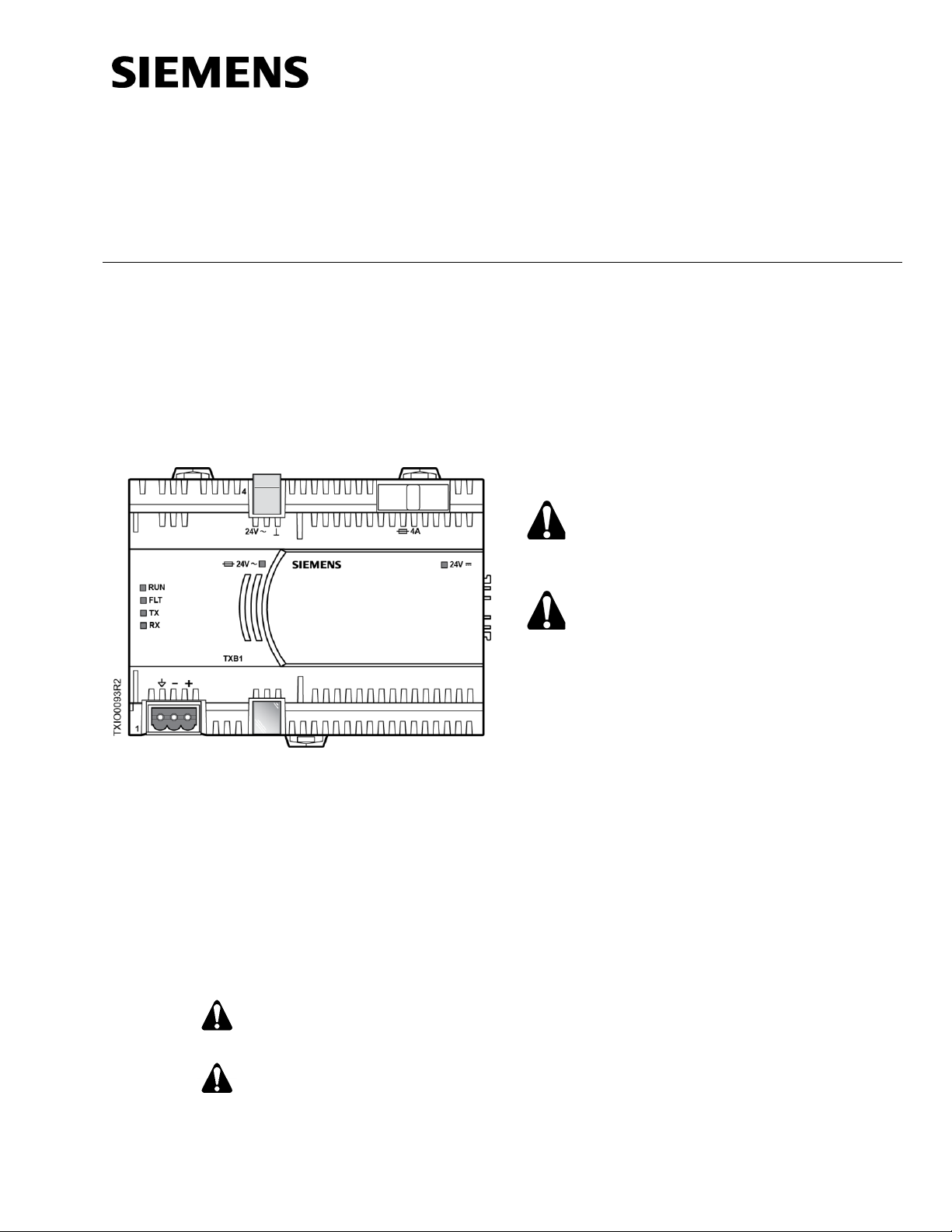
Figure 1. P1 Bus Interface Module Example (TXB1.P1-4).
Product Numbers
TXB1.P1
TX-I/O Bus Interface Module, P1
(10 modules, if needed may share
power with TXS1.12F4 TX-I/O
Power Supply)
TXB1.P1-4
TX-I/O Bus Interface Module, P1
(4 modules)
Warning/Caution Notation
WARNING:
Personal injury or property
damage may occur if you do not
follow a procedure as specified.
CAUTION:
Equipment damage or loss of
data may occur if you do not
follow a procedure as specified.
Required Tools and Materials
• Wire stripper/side cutter
• Small flat blade screwdriver
• Digital multimeter (DMM)
Expected Installation Time
7 minutes
Prerequisites
CAUTION:
No power wiring is connected to the field
panel controller or other TX-I/O
components at this time.
CAUTION:
The TX-I/O island bus must be mounted
on a DIN rail (1.38" × 0.3" × 0.04"
[35 mm × 7.5 mm × 1 mm]).
• For energy management installations, NEMA
Type 1 or better enclosure with DIN rails and
source of 24 Vac.
• For smoke control installations, PX Series
enclosures and service boxes. See the PX
Series Service Box Installation Instructions
(553-131).
• If mounting in an enclosure:
− Enclosure is installed.
− The power source is installed, as
applicable.
− The power is OFF.
• All necessary wiring is pulled and terminated
per the layout drawing.
• Power and communication wiring is terminated
to the removable plugs supplied with the
devices.
Page 2
Document No. 553-140
Installation Instructions
November 4, 2019
Page 2 of 4 Siemens Industry, Inc.
Power Requirements
One of the following power sources is pulled to the
enclosure:
• 120 Vac, 60 Hz and terminated at the 115V
PX Series Service Box.
• 230 Vac, 50/60 Hz and terminated at the 230V
PX Series Service Box.
• 24 Vac, 50/60 Hz Class 1 power limited from a
third-party transformer and connected to a
terminal block.
• If powering a TX-I/O expansion panel, power
wiring is run from the transformer in the
primary panel to the expansion panel, if
needed.
CAUTION:
For information on extending the TX-I/O
island bus outside the enclosure, see the
APOGEE Wiring Guidelines for Field
Panels and Equipment Controllers
(125-3002).
General Installation Requirements
CAUTION:
All devices not isolated by an Island Bus
Expansion module (TXA1.1BE) must be
connected to the same grounding point.
CAUTION:
Do not connect TX-I/O components to a
floating system neutral. Otherwise,
equipment damage will occur.
• System Neutral ( ) must be
continuous throughout the TX-I/O
Bus.
• System Neutral must be connected
to building approved earth-ground
( ) at a single point only at the
24 Vac transformer.
Installation
CAUTION:
Turn OFF AC power at the ON/OFF
switch in the Service Box or
transformer enclosure.
CAUTION:
UL Listings require that NEC Class I
and Class II wiring be kept separate
from each other. Use separate conduit
and cable tie bars to separate Class I
Digital Output (DO) wires from all other
Class II wiring.
CAUTION:
The TX-I/O island bus must extend
from the male bus connector of the P1
Bus Interface Module (BIM).
- The P1 BIM supplies 24 Vac,
24 Vdc, and communication to I/O
modules on the male bus
connector.
CAUTION:
Only insert or remove the P1 BIM, TX-
I/O Power Supply, and Bus Connection
Module when the power is OFF.
This device includes electrical and
electronic components and must not
be disposed of as domestic waste.
Product recovery and disposal must
comply with all national and local
regulations.
NOTE:
For Smoke Control applications, the
field panel controller must be installed
in the lower half of the enclosure.
For more information, see TX-I/O I/O
Modules Installation for UL
Applications Installation Instructions
(553-141) and TX-I/O Power Supply
and Bus Modules Installation
Instructions (553-142).
Page 3

Document No. 553-140
Installation Instructions
November 4, 2019
Siemens Industry, Inc. Page 3 of 4
Basic Steps for Connecting Devices to the
DIN Rail
The island bus establishes its own connection when
TX-I/O devices are plugged into one another on a DIN
rail.
1. Slide out the mounting tabs.
2. Align the channel on the back of the device with
the DIN rail.
3. Using a flat blade screwdriver, push in each
mounting tab until it clips onto the DIN rail.
4. Align an I/O module with the Power Supply or Bus
Connection Module and slide the I/O module
down over the TX-I/O island bus connector.
5. Push in each mounting tab until it clips onto the
DIN rail.
Connecting Devices to the TX-I/O Island Bus.
Completing the Installation
CAUTION:
For RS-485 ALN or FLN, terminate only one
end of the shield wire on the enclosure earth
ground.
For a 3-wire system, terminal is connected
to reference wire. Protective ground terminal
may be connected to earth ground.
For a 2-wire system, terminal is not
connected. Protective ground terminal must
be connected to earth ground.
NOTE: Do not connect the power or network
communication cable until instructed to do so
during start-up.
1. Terminate power wiring to the 24 Vac removable
plug.
2. If necessary, terminate wires to the
communications terminals (CS and CD).
The installation is now complete.
Page 4

Document No. 553-140
Installation Instructions
November 4, 2019
Unrestricted Information in this document is based on specifications believed correct at the time of publication. The right is reserved to make
changes as design improvements are introduced. APOGEE and Insight are registered trademarks of Siemens Industry, Inc. Other product or
company names mentioned herein may be the trademarks of their respective owners. © 2019 Siemens Industry, Inc.
Siemens Industry, Inc.
Smart Infrastructure
1000 Deerfield Parkway
Buffalo Grove, IL 60089-4513
+1 847-215-1000
Your feedback is important to us. If you have
comments about this document, please send them
to sbt_technical.editor.us.sbt@siemens.com.
Document No. 553-140
Printed in the USA
Page 4 of 4
Configuring the 4-Module P1 BIM
1. Power up the P1 BIM.
2. Plug in the USB on both ends (the device side to
the P1 BIM; the host side to the computer).
The device will be automatically recognized and
installed.
3. Open Windows Explorer.
4. Find the USB device/drive (will say SIEMENS
P1BIM Configuration Tool) in the drives list.
5. Open the drive.
6. Double-click P1BIMCFG.exe to launch the
application.
The following dialogue box displays:
7. Select the desired Baud Rate from the drop-down
menu. (Note: Only 4800 and 38400 are supported
rates.)
8. Click Apply.
9. Verify that the baud rate you selected is displayed
in the Baud Rate field.
10. Enter the desired address in the P1 Address field.
The default address is 99, but the device will not
communicate if left at the default address. Valid
P1 addresses are 1 through 98.
11. Click Apply.
12. Verify that the address you entered is displayed in
the P1 Address field.
 Loading...