

Siemens OZW672.01, OZW672.04, OZW672.16 Commissioning Instructions
s
LPB and BSB plants
Web Server OZW672... V6.0
Commissioning instructions
OZW672.01
OZW672.04
OZW672.16
CE1C5712en
2015-10-13 Building Technologies

Siemens Switzerland Ltd
www.siemens.com/buildingtechnologies
Building Technologies Division
International Headquarters
Gubelstrasse 22
6301 Zug
Switzerland
Tel. +41 41-724 24 24
2 / 143
Siemens Web Server OZW672... V6.0 CE1C5712en
Building Technologies 2015-10-13
© Siemens Switzerland Ltd, 2010
Subject to change

Table of contents
1 Overview .............................................................................................. 7
1.1 Introduction ............................................................................................ 7
1.2 Display and operating elements ............................................................. 9
1.3 Web operation ..................................................................................... 10
1.3.1 User levels ........................................................................................... 12
1.4 Symbols, notations, abbreviations ........................................................ 13
1.4.1 Symbols .............................................................................................. 13
1.4.2 Notations ............................................................................................. 14
1.4.3 Abbrev iations ....................................................................................... 14
2 Commissioning .................................................................................. 15
2.1 Prerequisites........................................................................................ 15
2.2 Getting started ..................................................................................... 16
2.2.1 Turn on Web Server ............................................................................. 16
2.2.2 Log into Web Server ............................................................................ 17
2.3 Administer user accounts ..................................................................... 19
2.4 Create device web pages ..................................................................... 21
2.5 Web Server settings ............................................................................. 25
2.5.1 Operating page "Inputs" ....................................................................... 25
2.5.2 Operating page "Time of day/date" ....................................................... 25
2.5.3 Operating page "Faults current" ........................................................... 26
2.5.4 Operating page "Settings" .................................................................... 26
2.5.5 Operating page "Device information" .................................................... 36
2.6 Commission network components ........................................................ 37
2.6.1 Access via portal.................................................................................. 37
2.6.2 Access via home network (LAN) .......................................................... 37
2.6.3 Access via direct connection ................................................................ 38
2.7 Functional check .................................................................................. 40
2.8 Additional settings ................................................................................ 42
2.9 Final steps ........................................................................................... 43
2.9.1 Check faults ......................................................................................... 43
2.9.2 Final steps on Web Server ................................................................... 43
2.10 Supply state ......................................................................................... 44
2 .11 Update software................................................................................... 44
3 Remote access via portal .................................................................. 45
3.1 Set up access via portal ....................................................................... 45
3.1.1 Portal and plant roles ........................................................................... 49
3.2 Prevent connection to portal................................................................. 49
4 Operate using a web browser ........................................................... 50
4.1 Overview ............................................................................................. 50
4.2 Operate the plant ................................................................................. 52
4.2.1 Bus device operation ........................................................................... 52
4.2.2 Operate Web Server ............................................................................ 52
4.2.3 Web Server diagnostics ....................................................................... 54
4.3 Faults .................................................................................................. 58
4.3.1 Overview ............................................................................................. 58
4.3.2 Web Server faults ................................................................................ 58
3 / 143
Siemens Web Server OZW672... V6.0 CE1C5712en
Building Technologies Table of contents 2015-10-13

4.3.3 Faults: Fault inputs 1…2 ...................................................................... 59
4.4 File transfer ......................................................................................... 60
4.5 Operation with ACS790 ........................................................................ 63
5 Visualize plants .................................................................................. 64
5.1 Overview ............................................................................................. 64
5.2 Example of a plant web page ............................................................... 65
5.3 Plant web page features ...................................................................... 66
5.4 Toolbar ................................................................................................ 67
5.5 Import web-capable plant diagrams ..................................................... 68
5.6 Create own plant web pages ................................................................ 70
6 "Energy indicator" function .............................................................. 74
6.1 Introduction.......................................................................................... 74
6.1.1 Function description ............................................................................. 74
6.1.2 LPB/BSB bus topology......................................................................... 75
6.1.3 LPB/BSB devices ................................................................................ 76
6.1.4 Navigation and device web pages ........................................................ 76
6.2 "Energy indicator" function levels ......................................................... 77
6.2.1 "Plant" level ......................................................................................... 77
6.2.2 "Partial plants" level ............................................................................. 78
6.2.3 "Data points" level................................................................................ 79
6.2.4 Number of "Monitored data points" ....................................................... 80
6.2.5 "Energy indicator" visibility ................................................................... 81
6.2.6 Summary display "Energy indicator" for a plant .................................... 82
6.3 "Energy indicator" commissioning function ........................................... 83
6.3.1 Commissioning notes........................................................................... 83
6.3.2 Start "Energy indicator" function ........................................................... 83
6.3.3 Estimated processing time ................................................................... 84
6.3.4 Deactivating "Data point monitoring" .................................................... 84
6.3.5 Activating "Data point monitoring" ........................................................ 86
6.4 Dialog boxes, data points, and "Green limits" ....................................... 88
6.4.1 General dialog boxes ........................................................................... 88
6.4.2 Dialog boxes with numeric data points ................................................. 89
6.4.3 Dialog boxes with enumeration data points .......................................... 90
6.4.4 User groups "Service" and "End user" .................................................. 90
6.5 E-mail with "Energy indicator" for the plant ........................................... 91
6.5.1 E-mail receiver configuration ................................................................ 91
6.5.2 Mail inbox ............................................................................................ 92
6.5.3 E-mail contents .................................................................................... 93
6.6 Exceptions ........................................................................................... 94
7 Communications................................................................................ 95
7.1 Remote operation ................................................................................ 95
7.1.1 Access via portal ................................................................................. 95
7.1.2 Access via home network (LAN) .......................................................... 96
7.1.3 Access via direct connection .............................................................. 100
7.2 Messages via e-mail .......................................................................... 104
8 Trend functions ................................................................................ 109
8.1 Overview ........................................................................................... 109
8.2 Define Trend ...................................................................................... 110
8.2.1 Define Trend via web ......................................................................... 110
4 / 143
Siemens Web Server OZW672... V6.0 CE1C5712en
Building Technologies Table of contents 2015-10-13

8.2.2 Bus load restriction ............................................................................ 113
8.2.3 Reset Trend definition ........................................................................ 113
8.2.4 Add Trend data points ........................................................................ 114
8.2.5 Manage Trend memory ...................................................................... 115
8.3 Send Trend data by e-mail ................................................................. 115
8.3.1 Configure E-mail receiver ................................................................... 116
8.3.2 Set transmission options per Trend channel ....................................... 117
8.3.3 E-mail contents and appendix ............................................................ 118
8.4 Download Trend file via web .............................................................. 119
8.5 Graphical trend display ...................................................................... 121
8.6 Import/export Trend definitions ........................................................... 122
8.7 ACS Trend ......................................................................................... 125
8.7.1 ACS offline Trend compatibility........................................................... 125
8.7.2 ACS Trend bus load ........................................................................... 126
9 Appendix .......................................................................................... 127
9.1 General notes .................................................................................... 127
9.2 Diagnostics ........................................................................................ 127
9.2.1 Web Server fault codes ...................................................................... 127
9.2.2 Windows commander ........................................................................ 128
9.3 Communications ................................................................................ 129
9.3.1 Internet protocol ................................................................................. 129
9.3.2 Free e-mail account providers ............................................................ 129
9.3.3 Install RNDIS driver ........................................................................... 130
9.3.4 Alternative network configuration ....................................................... 131
9.4 Glossary of Ethernet and Internet terms ............................................. 133
Index .......................................................................................................... 140
5 / 143
Siemens Web Server OZW672... V6.0 CE1C5712en
Building Technologies Table of contents 2015-10-13

6 / 143
Siemens Web Server OZW672... V6.0 CE1C5712en
Building Technologies Table of contents 2015-10-13
1 Overview
1.1 Introduction
Type summary
Document contents
Product number Max. number of monitored devices
OZW672.01 1 LPB or 1 BSB device
OZW672.04 4 LPBs or 1 BSB device(s)
OZW672.16 16 LPBs or 1 BSB device(s)
The document describes commissioning and operating the Web Server OZW672...
In this edition of "Web Server OZW672… Version 6.0" the following extensions
were added:
· New default password and minimum password strength. See Sections 2.2.2 and
2.5.4
· Change to absolute timeout. See Sections 2.5.4.3 and 4.1
· Response to incorrect login. See Section 4.1
· Response to communication problems for trend queries. See Section 8.2.1
· Synchronize trends. See Sections 8.2.1and 8.3.2
· New function "Trend graph". See Section 8.5
· Additional fault codes. See Section 9.2.1
· Continuous access. See Section 9.3.1
The current version of the user’s guide can be downloaded at
www.siemens.com/ozw672-manual.
Focus on web
browser operation
Important notes
Safety /
Product liability
The ACS790 PC software can also be used to commission and operate the Web
Server OZW672... To simplify reading, this document focuses on commissioning
and operating via web browser.
This symbol draws your attention to special safety notes and warnings.
Ignoring this type of note may result in device damage and personal injury.
· Devices may only be used in building technical plants and for the described
applications only. Comply with all local regulation (installation, etc.).
· Disconnect the power and immediately replace a defective or obviously
damaged device.
· Do not open the device. Failure to comply will invalidate any warranty claims.
· The technical data are provided solely for use with Siemens bus devices. The
user ensures the functionality of operation when using third-party devices not
expressly mentioned here. Siemens assumes no responsibility for service and
warranty under these circumstances.
7 / 143
Siemens Web Server OZW672... V6.0 CE1C5712en
Building Technologies Overview 2015-10-13

Intended use
Trouble-free and safe product operation presupposes transport, storage, mounting,
installation, and commissioning as intended as well as careful operation.
Disposal
Dispose of the device as electronic waste in compliance with European directive
2002/96/EEC (WEEE) and not as municipal waste. Observe all corresponding
national, legal regulations, and dispose of the device via appropriate channels.
Comply with all locally applicable laws and regulations.
8 / 143
Siemens Web Server OZW672... V6.0 CE1C5712en
Building Technologies Overview 2015-10-13
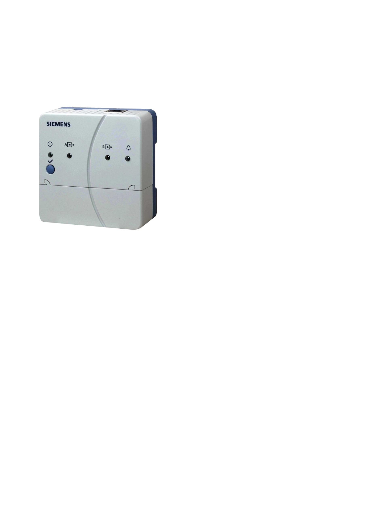
Overview
LED displays
1 (red/
green/orange)
2 LPB/BSB A
(green)
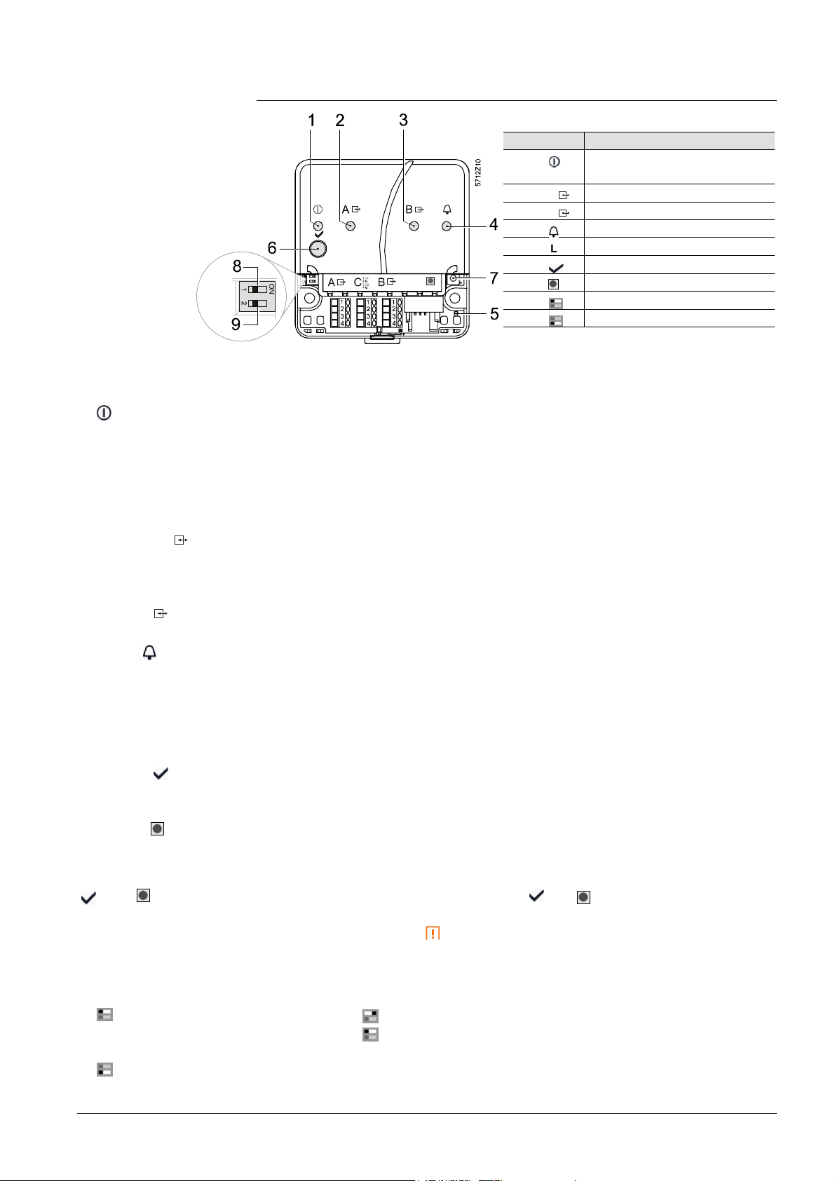
1.2 Display and operating elements
Pos Name
1 On LED, Operation and
"Energy indicator"
2 A LPB/BSB LED
3 B No function
4 Fault LED
5 (LED) No function
6 Remote button
7 Service button
8 Message suppression switch
9 No function
· Dark No power.
· Steady red Web Server starts operating system.
· Flashing red Web Server starts application.
· Steady green Web Server operational, "Energy indicator" = "Green leaf".
· Steady orange Web Server operational, "Energy indicator" = "Orange leaf".
· Flashing Web Server operational, connected to the portal
green / orange (LED 0.8 s on, 0.2 s off)
· Dark No bus power.
· Lit LPB/BSB operational.
· Flashing Communication on LPB/BSB.
3 (LED) B
4 Faults (red)
5 (LED)
Operating buttons
6 Remote
7 Service
Button combinations
and
Switch
8 Message inhibition
No function.
· Dark No fault (normal operating state).
· Lit Fault exists.
No function.
· Long (> 6 s) Sends system report to fault e-mail recipients
(not to "Energy indicator" and Trend data recipients)
· Long (> 6 s) See "Button combinations".
· Long (> 6 s) Simultaneously press and
restores default factory
settings.
Note : All configuration data and settings are reset. The
device list, uploaded files, and all unsent messages are
deleted. History data is not deleted.
· Position "On" Messages cannot be sent.
· Position "Off" Message sending allowed.
9 (DIP switches)
Siemens Web Server OZW672... V6.0 CE1C5712en
Building Technologies Overview 2015-10-13
No function.
9 / 143
1.3 Web operation
Primary navigation
Secondary
Command
Plant state
Plant state
The Web Server user interface is queried via a web browser.
· The Web Server provides a text-based operation of Web Server by default and
connected Synco devices (Section 3).
· In addition, you can also set up visualized operation (Section 5).
The following describes the display areas for the text-based standard user
interface (display areas for visualization are outlined in Section 5).
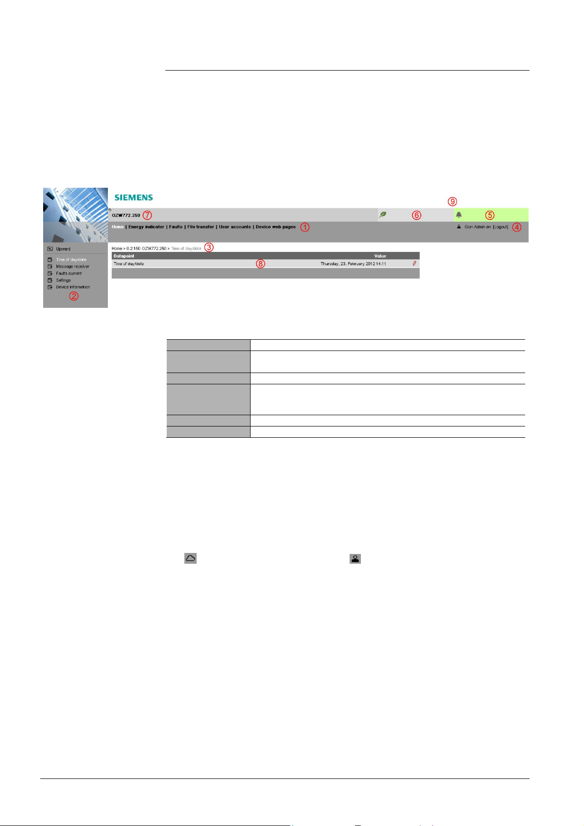
The main window is sub-divided into various display areas.
navigation
sequence
User
fault
The following main functions are selected via primary navigation:
Home Menu-based plant and device operation.
Energy indicator Display and operate "Energy indicator" data points.
(displayed only if the controller with the Energy indicator is connected)
Faults Display system faults.
File transfer Create and manage Trend functions
Download of event history,
upload of documents, logos and system definitions.
User accounts User administration.
Device web pages Create device list and operating pages.
Device operation (via home) queries devices and their operating pages via
secondary navigation (menu tree).
The path displays the workflow starting at the main menu to the open operating
page. Simply click at any point on the path to return to that location.
This field shows the currently logged-in user. Clicking [Logout] ends the current
session. The session remains active until logout. When connecting via the portal
the symbol is displayed instead of the symbol and the user’s email address
is displayed rather than the user name.
The "Plant state fault" field is displayed permanently:
· Green field: No fault
· Red field: Plant fault
Click the "Plant state fault" field to display all faults in the plant.
Energy indicator
10 / 143
Siemens Web Server OZW672... V6.0 CE1C5712en
Building Technologies Overview 2015-10-13
The "Plant state Energy indicator" field is displayed permanently:
· Green leaf: All "Energy indicator" data points are always within
their "green limits", i.e. "within the green/allowed range".
· Orange leaf: One or multiple "Energy indicator" data points are
outside their "green limits"
Clicking the "Plant state Energy indicator" field opens the "Energy indicator"
function.

Plant name
Display
Logo area
Displays plant name as entered.
The display range displays content corresponding to the selected function via
primary and secondary navigation.
Shows Logo 1 and Logo 2.
11 / 143
Siemens Web Server OZW672... V6.0 CE1C5712en
Building Technologies Overview 2015-10-13
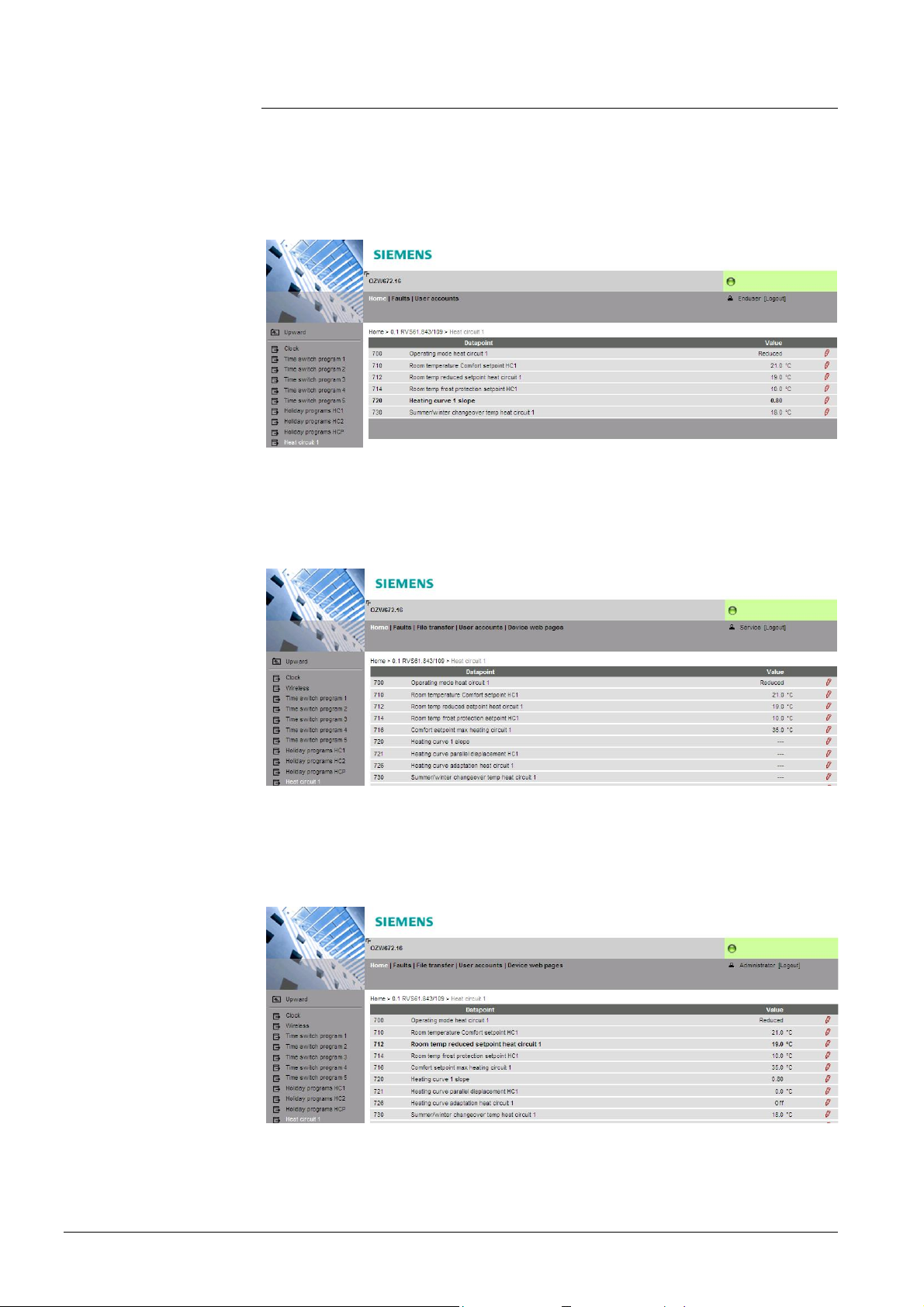
1.3.1 User levels
Display and operation depend on the access level of the logged in user:
End user
Service
· Operate end user data.
· Fault overview
· Administer own user account.
The same as end user, plus:
· Operate service and end user data.
· Trend functions, Documents, Message history, Logos, and System definitions.
Administrator
The same as service, plus:
· Creation of device list and web pages
· Toolbar to create plant web pages
· Management of all user accounts
12 / 143
Siemens Web Server OZW672... V6.0 CE1C5712en
Building Technologies Overview 2015-10-13
1.4 Symbols, notations, abbreviations
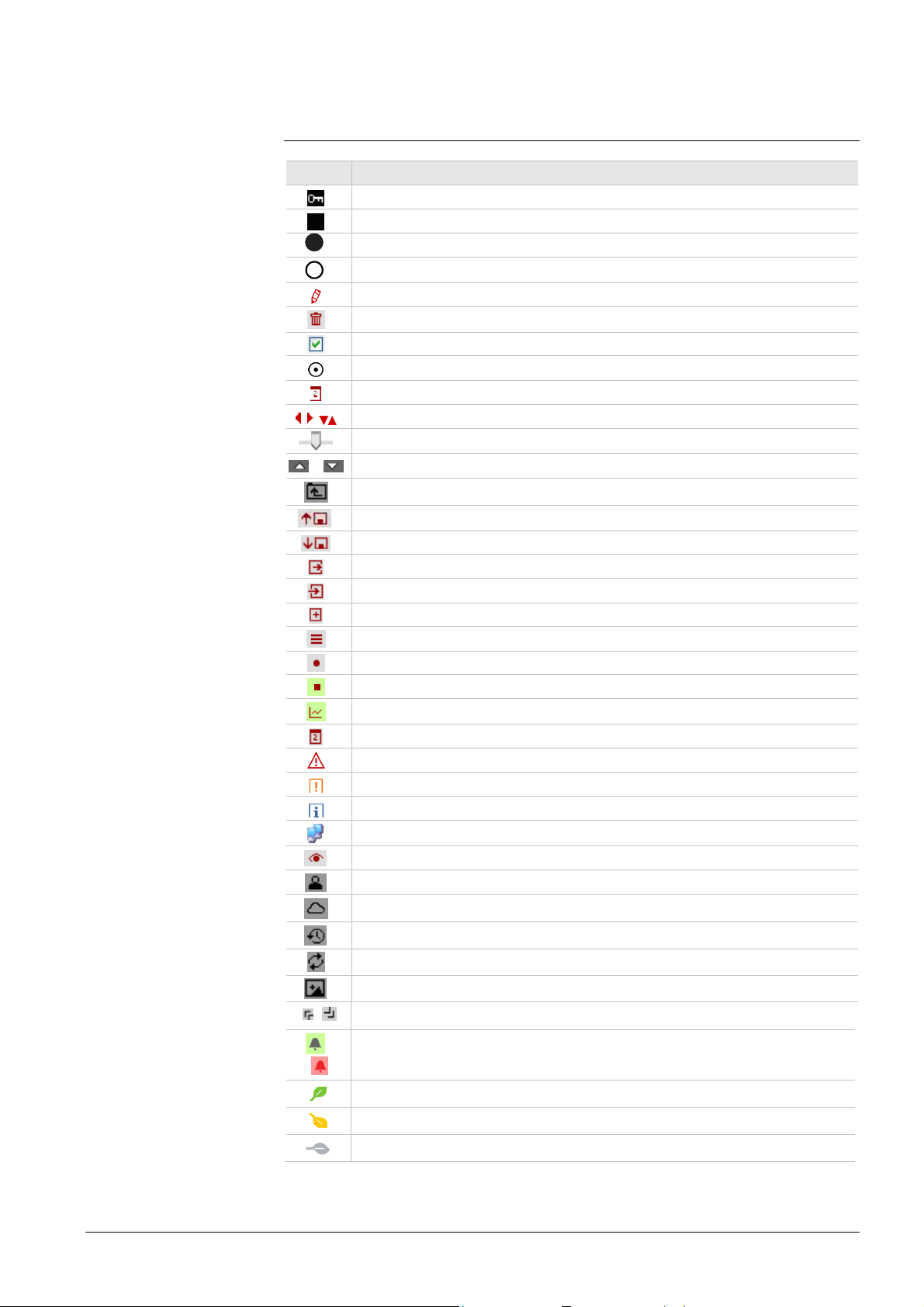
1.4.1 Symbols
Symbols
Symbol Meaning
Data point at the service level.
Data point at the end us er level.
Read/write data point; the setting value can be changed.
Read-only data point; the value cannot be changed.
Link to entry field.
Delete object.
Checkbox.
Selection box.
Cal en dar.
Arrows to incrementally adjust values.
Adjustment tab.
/ Arrow to display sort order.
Up.
File upload (to Web Server).
File download (f rom W eb Server).
Export file
Import file
Add data point
Move/sort data point
Start Tr end
Stop Trend
Generate graph
Calendar to select date
Safety note, intended to protect against misuse.
Always obs erve/follow.
Note; important information.
Network c onnection.
Link to device.
User connected locally or via direct connection (fixed or dynamic IP address).
User connected via portal.
Message history.
System definitions
Logos.
,
Switch over displays: Full view, partial view
/
Fault indication: Green field = no f ault; red field = f ault (alarm)
"Green leaf"
"Orange leaf"
"Grey leaf"
13 / 143
Siemens Web Server OZW672... V6.0 CE1C5712en
Building Technologies Overview 2015-10-13

1.4.2 Notations
Command sequences
IP address, domains
portal
Buttons
Abbreviations
Menu command sequences are printed as follows:
· Web Server: Home > 0.5 OZW 672... > Settings > Time of day/date
· PC: Start > Settings > Network connections > Local Area Connection
OZW672... stands for: OZW672.01 or
OZW672.04 or
OZW672.16
Entry in the web browser address line:
· IP address: 192.168.2.10
· Domains: www.siemens.com
· Portal: https://www.climatixic.com
Buttons are written as follows: [ Add ]
1.4.3 Abbreviations
Auto MDI-X Auto Medium Dependent Interface - Crossed
DHCP Dynamic Host Configuration Protocol
DynDNS Dynamic Domain Name System
HTTP Hyper Text Transfer Protocol
HTTPS Hyper Text Transfer Protocol Secure
IP Internet Protocol
LPB Local Process Bus
BSB Boiler System Bus
NAT Network Address Translation
PAT Port and Address Translation
RNDIS Remote Network Driver Interface Specification
STP Shielded Twisted Pair
TCP Transmission Control Protocol
TLS Transport Layer Security
UPnP Universal Plug and Play
USB Universal Serial Bus
Web API Web Application Programming Interface
The glossary, see section 9.4, includes further explanations on abbreviations and
terms are available in the appendix.
14 / 143
Siemens Web Server OZW672... V6.0 CE1C5712en
Building Technologies Overview 2015-10-13

2 Commissioning
This section describes how to commission the Web Server.
2.1 Prerequisites
General
Notes
Portal commissioning
requirements
The following conditions must be met to commission the Web Server:
· The Web Server is mounted and wired (see Installation instructions, G5711).
· The connected bus device is commissioned.
· The bus device has a valid address and is operational.
· The bus device works trouble free; the fault LED is not lit.
· The bus power supply to the bus device is turned on.
· Recommended by clock time supplier: The LPB bus device is clock slave
with remote setting.
· Connecting a SmartPhone App to a Web Server makes sense only after the
Web Server is fully commissioned.
· The Web Server recognizes whether LPB or BSB devices are connected to the
bus
· The Web Server automatically receives its IP address from the router when the
DHCP client is switched on. The address without router is: 192.168.2.10
setting, see Section 7.1.2)
· Connecting a SmartPhone App to a Web Server makes sense only after the
Web Server is fully commissioned.
The following is required to commission the Web Server on the portal:
· The Web Server is connected to the Internet
(factory
Local commissioning
requirements without
portal
Operating notes
The Web Server automatically registers on the portal.
The operation LED starts to flash green / orange as soon as the Web Server is
connected to the portal.
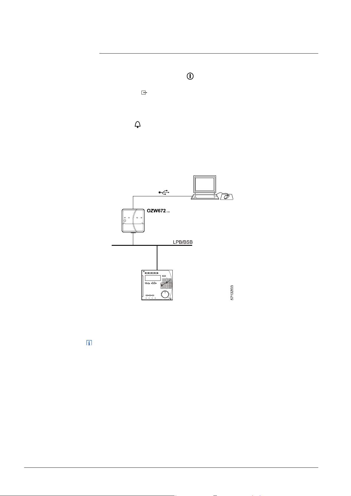
The following is required to commission the Web Server:
A PC/laptop and a web browser commission Web Server via an USB interface. The
RNDIS driver must be installed to connect via USB. IP address USB:
192.168.250.1
The address range 192.168.250.1 - 192.168.250.255 cannot be used for Ethernet
and is reserved exclusively for USB.
· The RNDIS driver is automatically installed when connecting via USB if the
PC/laptop is connected to the Internet (as long as the Microsoft online update
service is enabled). The RNDIS driver can be installed manually if there is no
connection to the Internet (see Section 9.3.3)
· The RNDIS is supplied on the Web Server at
http://<IP-Adresse>/drivers/
· Always start with primary navigation before going to secondary navigation to go
to the menu item.
· Back: Click symbol "Up" or navigate via path or primary navigation.
(cannot be changed)
15 / 143
Siemens Web Server OZW672... V6.0 CE1C5712en
Building Technologies Commissioning 2015-10-13
2.2 Getting started
2.2.1 Turn on Web Server
Turn on Web Server
Connect the Web Server to the power supply and connect it to the PC:
1. Connect power supply to turn on power on Web Server. The Web Server is
operational, when the green LED is lit.
2. Check additional displays:
· LED A
Green light if LPB/BSB bus power supply is available. Check the LPB/BSB
bus wiring and setting for the bus power supply on the bus device if no bus
power supply is available.
· LED
Dark if no fault is pending. You can resolve pending faults later (see
Section 2.9).
3. Plug the supplied USB cable into the Web Server and the PC and start up the
PC. The PX recognizes the Web Server as a USB device. Otherwise, the
RNDIS is still not installed.
4. The RNDIS driver is installed automatically if the PC is connected to the
Internet and no RNDIS driver is installed. The installation wizard will guide you
through installation.
Note
16 / 143
Siemens Web Server OZW672... V6.0 CE1C5712en
Building Technologies Commissioning 2015-10-13
You can also manually set up the RNDIS driver (see Section 9.3.3).
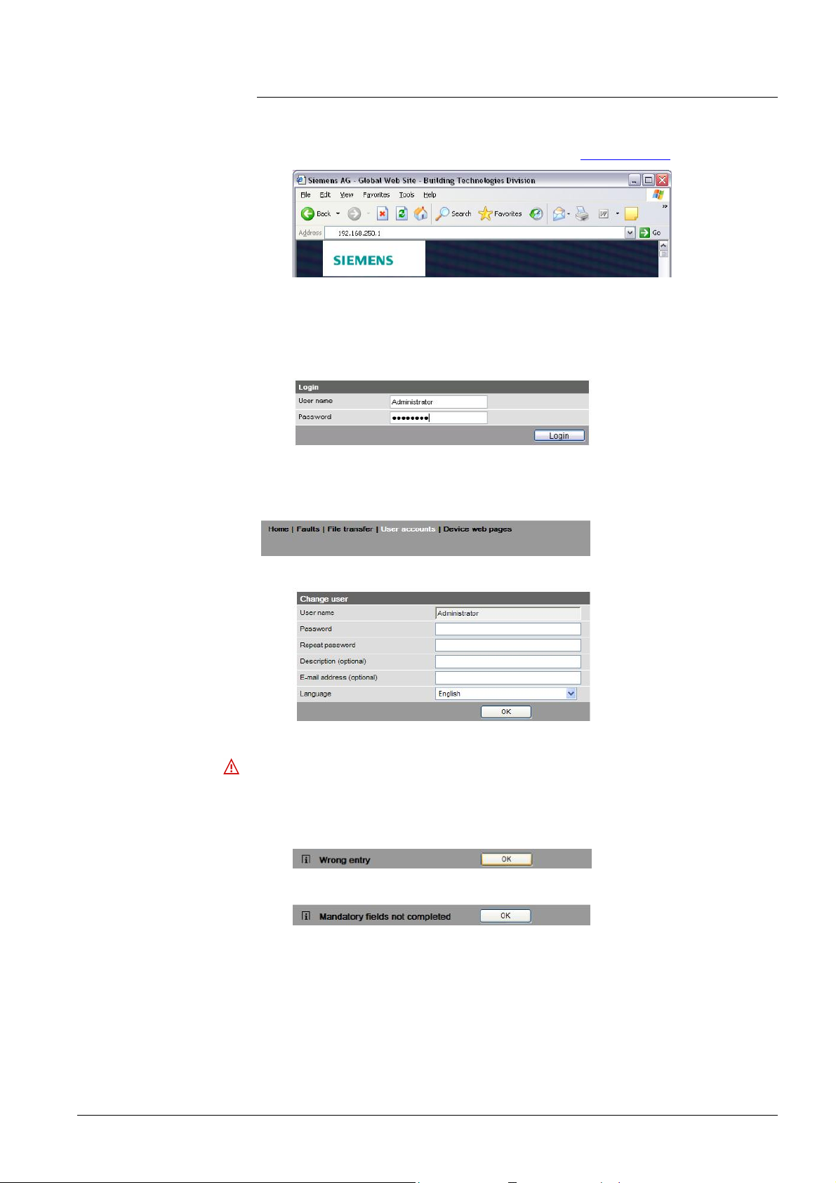
2.2.2 Log into Web Server
Log in
A PC with USB interface and web browser is used to commission the Web Server.
1. Start web browser.
2. In the address line, enter the USB IP address (192.168.250.1).
3. First time Login
· User name Administrator
· Password to V5.2(Passwort): Password
· Password as of V6.0 (Password): Password.1
·
4. Click [ Login ] to finish.
5. After logging on the first time, the dialog box is displayed to define a new
password (Web-Server-Sprache English).
Important note
· A new password must be defined the first time you log in (you can also change
the language).
· You cannot exit the dialog box if you do not define a new password (i.e. not
equal to "Password" resp. "Password.1") and the following note is displayed:
· The following message is displayed if you fail to fill out all required fields:
17 / 143
Siemens Web Server OZW672... V6.0 CE1C5712en
Building Technologies Commissioning 2015-10-13

Password and user
name
Observe capitalization when entering the password.
The message "Entry incorrect" is displayed when entering an incorrect password.
Minimum password
strength
The password strength is checked when entering the password and a progress bar
displayed. The bar is orange is the password is week. It changes to green as soon
as the password is strong enough.
The following conditions must be met for a secure password:
· Minimum password length of 8 characters
· At least 1 capital letter
· At least 1 lowercase letter
· At least 1 number
· At least 1 special character
18 / 143
Siemens Web Server OZW672... V6.0 CE1C5712en
Building Technologies Commissioning 2015-10-13
2.3 Administer user accounts
Administer user
accounts
Note
Change
administrator data
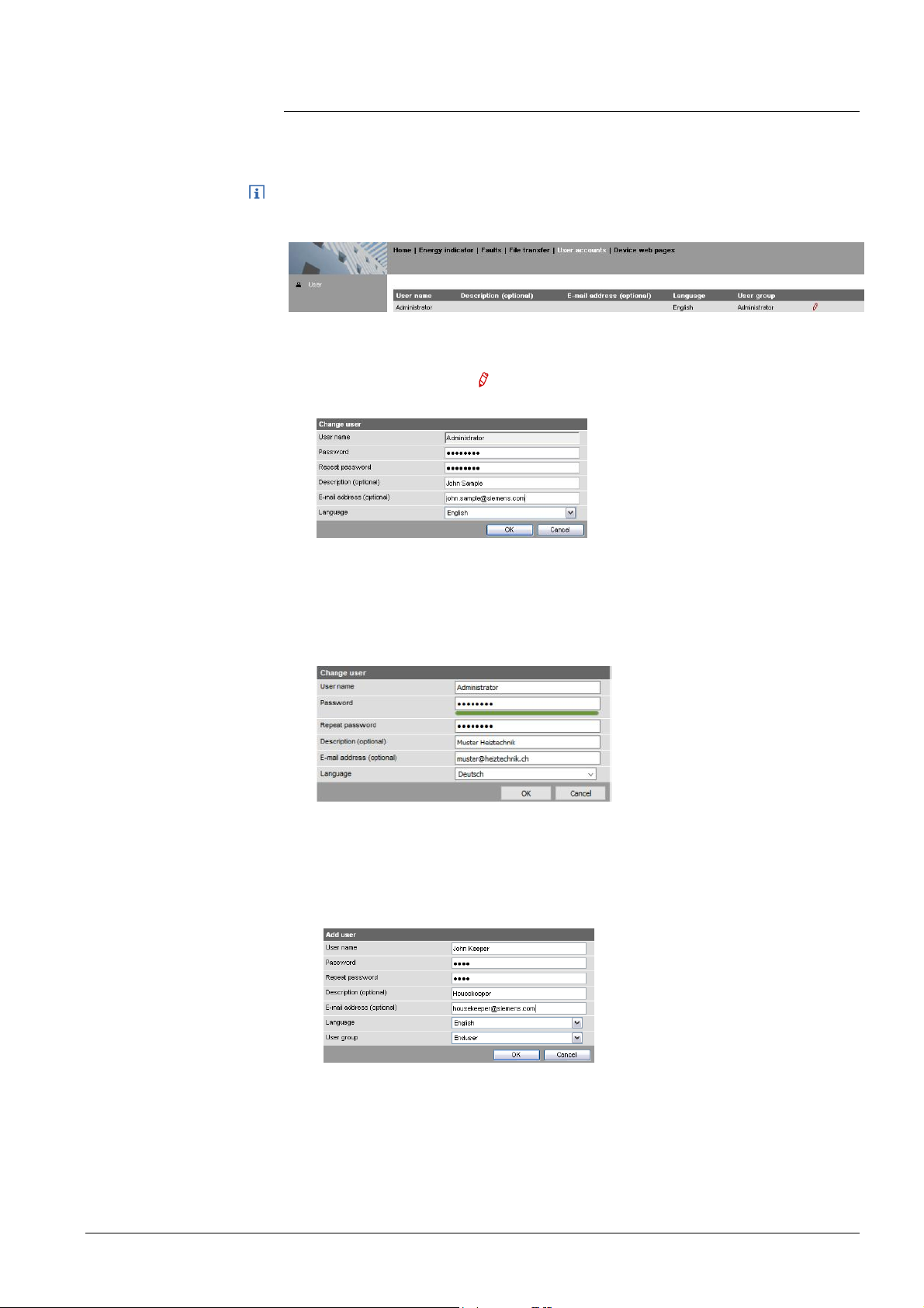
Use the "User accounts" menu to change the administrator password at delivery
and set up additional user accounts.
The user account settings equally apply to access via Smartphone app and other
applications via Web API.
Procedure:
1. Click red pencil symbol
.
The "Change user" dialog box opens.
2. Change administrator data:
- Password
- Repeat Password
- Description (optional)
- Email address (optional)
- Language: English
3. Click [ OK ] to finish.
Add a new user
Procedure:
1. Click [ Add ]
The "Add user"
Siemens Web Server OZW672... V6.0 CE1C5712en
Building Technologies Commissioning 2015-10-13
dialog box is displayed.
19 / 143
2. Enter / select user data:
- User name
- Password
- Repeat password
- Description (optional)
- E-mail address (optional)
- Language: English
- User group
3. Close with [ OK ]
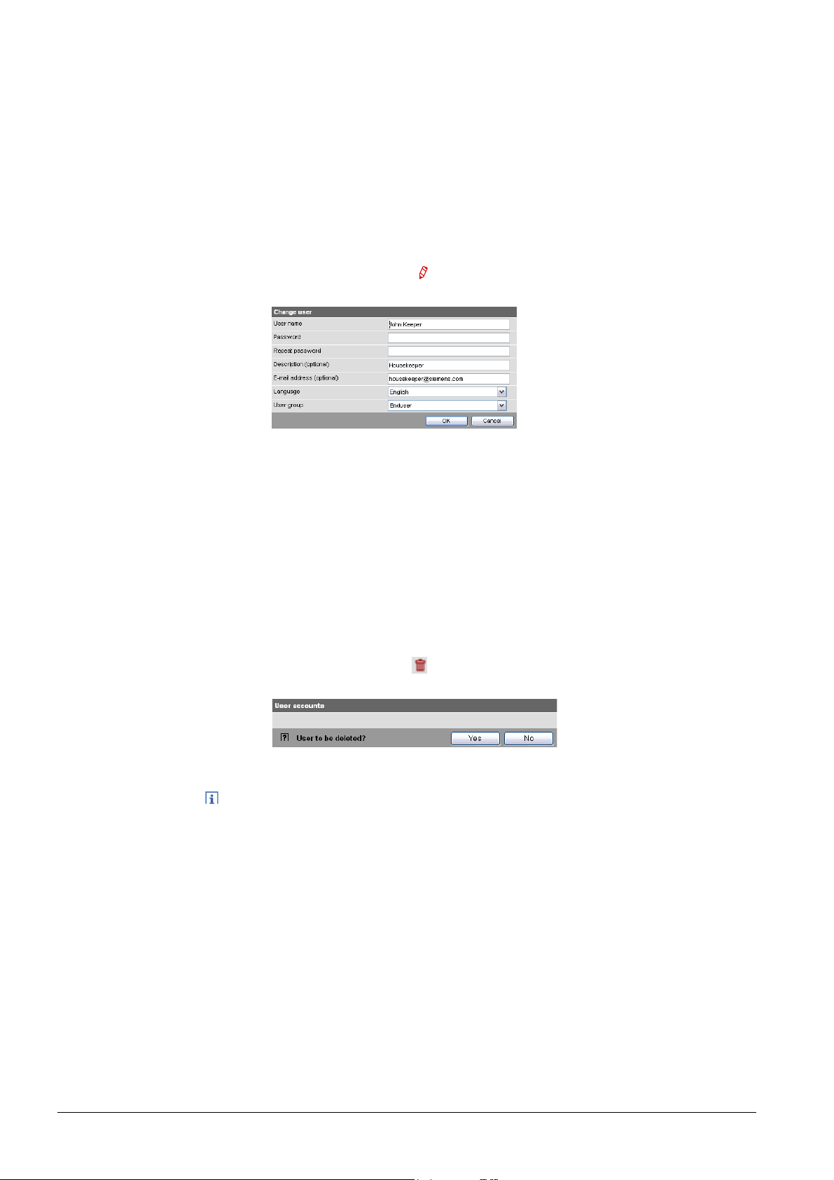
Change user data
Delete user account
Procedure:
1. Click red pencil symbol
Change user"
The "
for the corresponding user.
dialog box opens.
2. Change user data:
- User name
- Password
- Repeat password
- Description (optional)
- E-mail address (optional)
- Language: English
- User group.
3. Close with [ OK ]
Procedure:
1. Click red garbage can for the corresponding user.
The "User accounts" dialog box is displayed.
2. Click [ Yes ] for "User to be deleted?".
Notes
· The administrator account cannot be deleted. The name "Administrator" and
user group "Administrator" cannot be changed. You may, however, add user
accounts with administrator rights.
· You can only add new users and delete existing ones on the "Administrator"
user level.
· Changing other user accounts is reserved to the "Administrator" user level.
20 / 143
Siemens Web Server OZW672... V6.0 CE1C5712en
Building Technologies Commissioning 2015-10-13
2.4 Create device web pages
Create device
websites
Note
Notes
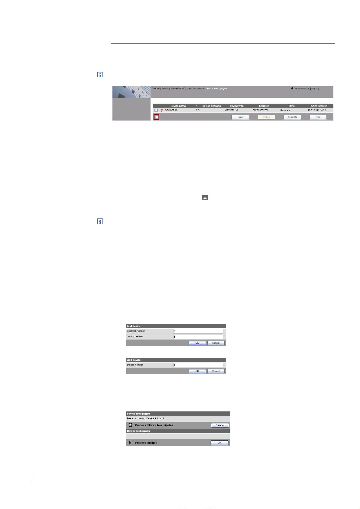
You must first add associated devices and device websites before you can operate
the Web Server and the bus device. To this via the "Device web pages" menu.
Device web pages can only be created on the "Administrator" user level.
Linked devices are listed in a table with the following information:
· Device name
· Device address
· Device type
· Serial number
· State
· Generated on
You can sort the table by clicking
· The Web Server itself is already in the device list.
· Only added bus devices are monitored.
· Device web pages can only be generated on the "Administrator" user level.
· Only generated bus devices can be operated.
· Changes to settings of the connected bus device may require that the device
web pages be recreated or updated to apply changes from web operation.
· You must delete and re-add a bus device after you update the bus device
software, or replace the bus device.
Add device
Procedure:
1. Click [ Add ]
2. Enter the bus address:
LPB: Segment number and Device number.
3. BSB: Device number (default: 1=basic device).
4. You can add just one BSB device to the device list.
5. Click [ OK ] to confirm.
The Web Server searches for a device with the entered bus address. It is
displayed in the device list if found.
21 / 143
Siemens Web Server OZW672... V6.0 CE1C5712en
Building Technologies Commissioning 2015-10-13
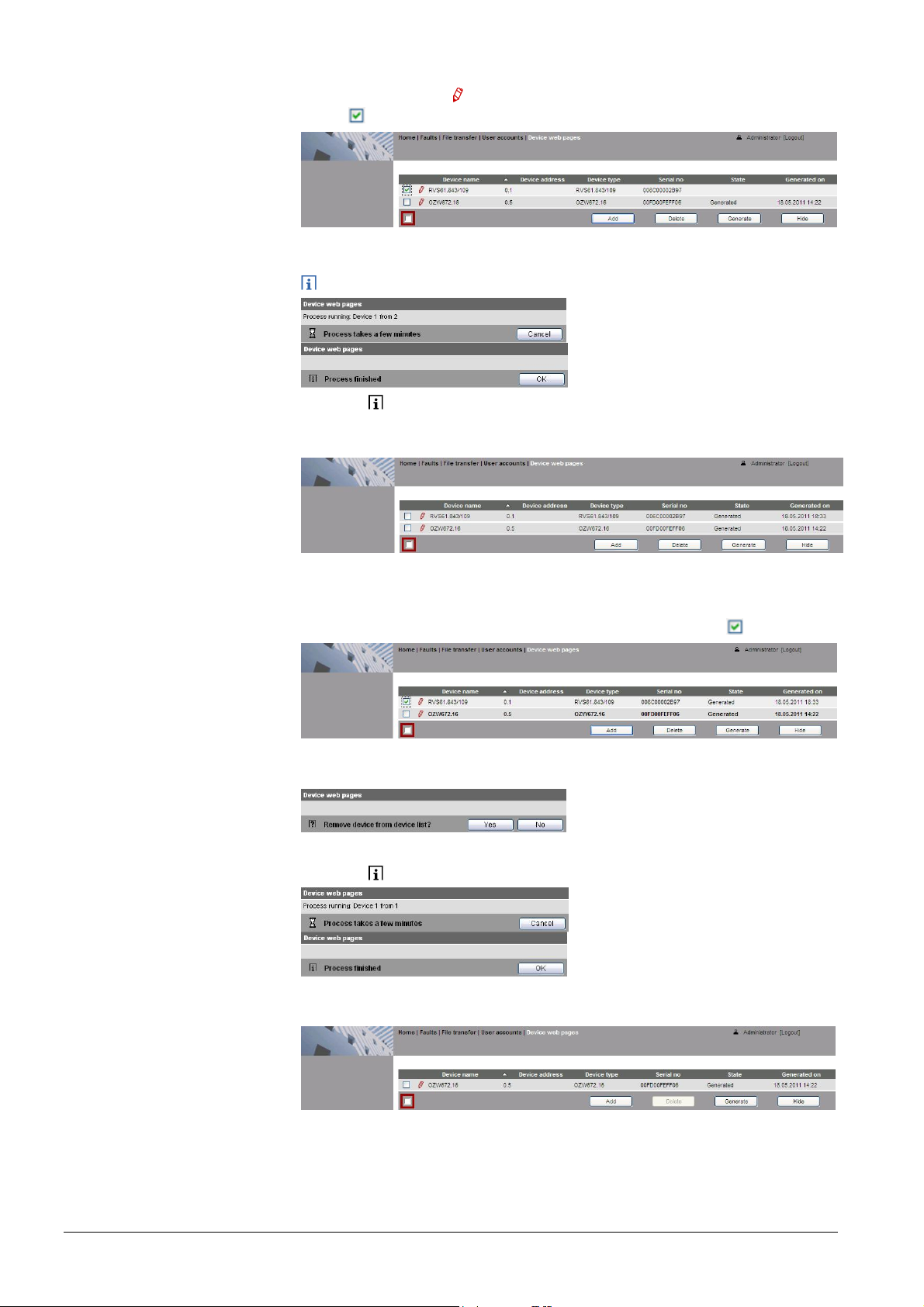
6. The added device can be named by clicking the red pencil symbol for the
corresponding device
. A maximum of 20 characters are available.
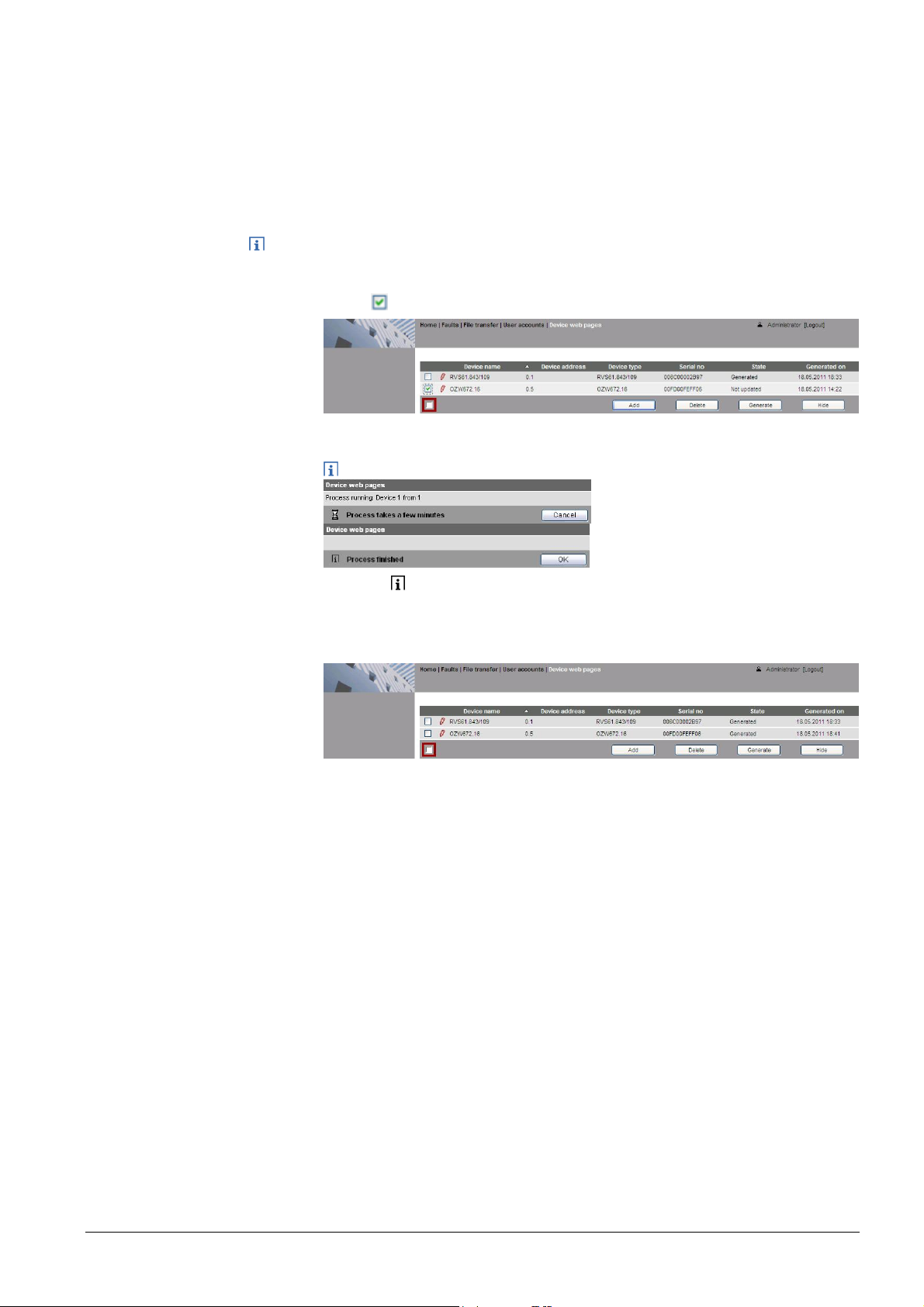
7. Select the devices whose web pages you want to create.
8. Click [ Generate ]
Device web pages are generated.
The process may take a few minutes.
9. Wait until Process finished is displayed.
In the device list, the Web Server and the bus device display state
"Generated".
Delete device
10. The device websites are now available under Home.
Procedure:
1. Select the bus device you want to remove from the device list .
2. Click [ Delete ]
3. Click [ Yes ] to confirm.
The Web Server removes the device from the device list.
4. Wait until Process finished is displayed.
5. Click [ OK ] confirm.
The device is removed from the device list.
22 / 143
Siemens Web Server OZW672... V6.0 CE1C5712en
Building Technologies Commissioning 2015-10-13
Create device
web pages
You must create device web pages for the following cases:
· After you add a device (see "Add device").
· Changes to settings of the connected bus device may require that the device
web pages be recreated to apply changes from web operation.
· For changes to be applied, you must recreate the device web pages after
you update the system definition (see Section 4.4, part "Upload system
definitions").
Note
Device web pages can only be created on the "Administrator" user level.
Procedure
1. Select the devices whose web pages you want to newly create.
2. Click [ Generate ]
Device web pages are generated.
The process may take a few minutes.
3. Wait until Process finished is displayed.
4. Close with [ OK ]
In the device list, the Web Server and the bus device display state
"Generated".
23 / 143
Siemens Web Server OZW672... V6.0 CE1C5712en
Building Technologies Commissioning 2015-10-13
Update device
websites
When you change one of the following texts, the status at the Web Server changes
from "Generated" to "Not updated":
· Message receiver 1…4
· Fault input 1…2
· Text for: No fault
· Text for: Fault
You can change the following texts without influencing device status:
· Name (Web Server).
· Bus device name.
You must update the device web pages of the Web Server to apply all text changes
to the menu.
Notes
· You can update device web pages on user levels "Administrator" and "Service".
· Click [ Update ] on the Service and [ Generate ] on the Administrator level to
start updating (see "Create device web pages").
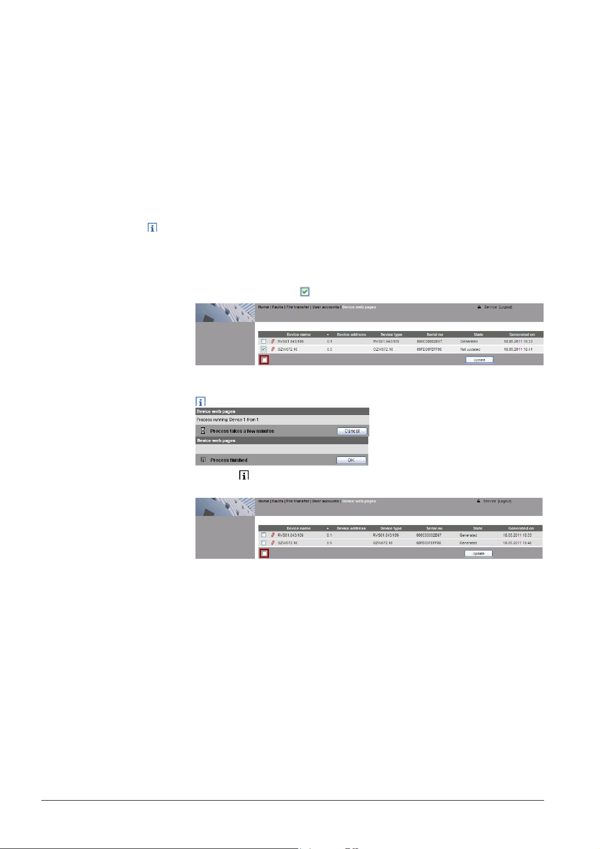
The following update procedure applies to the Service level:
1. Select the Web Server
.
2. Click [ Update ]
The device web pages are updated.
The process may take a few minutes.
3. Wait until Process finished is displayed.
The device list for the Web Server display state "Generated".
24 / 143
Siemens Web Server OZW672... V6.0 CE1C5712en
Building Technologies Commissioning 2015-10-13
2.5 Web Server settings
The "Home" menu is used to set the Web Server. The Web Server and then the
corresponding operating page are selected in secondary navigation.
Notes
Time of day/date
· The settings depend on the user level.
· This section does not describe read-only data points.
2.5.1 Operating page "Inputs"
The operating page displays the state of data points "Fault input 1" and "Fault
input 2".
Path: Home > 0.5 OZW672… > Inputs
A description of the data points is available in Section 4.3.3 "Faults: Fault inputs
1…2".
Setting the fault inputs is described in Section 2.5.4.8 "Inputs".
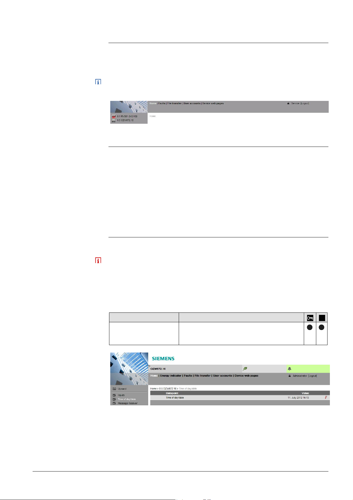
2.5.2 Operating page "Time of day/date"
Path: Home > 0.5 OZW672… > Time of day/date
Backup battery
The clock has a backup battery for at least 72 hours. The clock continues to run
after power failure for the duration of the backup battery.
Both date and time are reset in case of an extended interruption.
· The time is corrected automatically if the time is synchronized to the master
clock on the LPB/BSB bus (see Section 2.5.4, LPB / BSB).
· Otherwise, both date and time must be newly set.
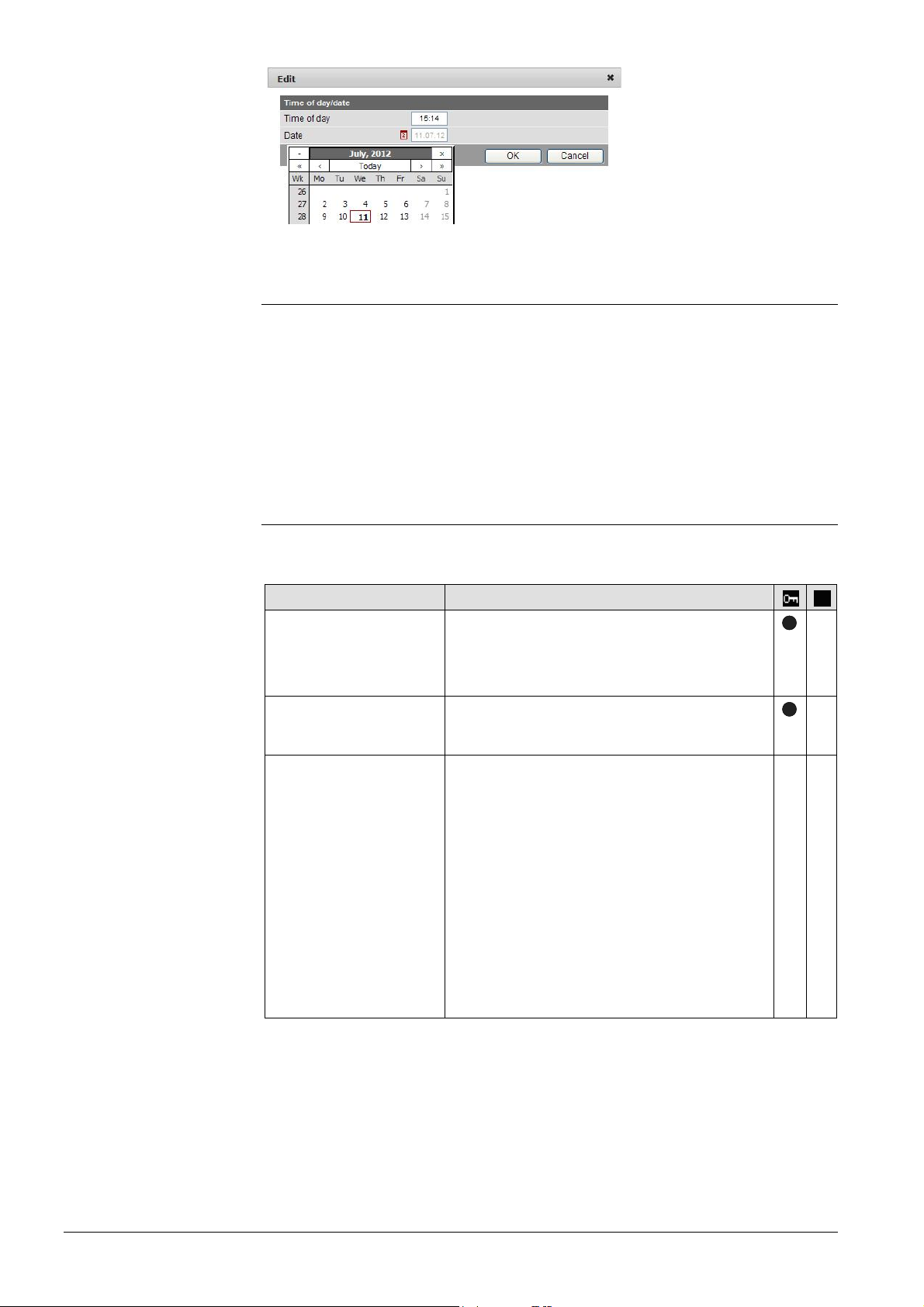
Data point Explanation, example
Time of day/date
Default val: 00:00 1.1.2005
Setting val: Time of day/date
Set the current time and date.
Weekday is calculated automatically.
25 / 143
Siemens Web Server OZW672... V6.0 CE1C5712en
Building Technologies Commissioning 2015-10-13
2.5.3 Operating page "Faults current"
Local faults and faults in system are displayed under "Faults current".
Path: Home > 0.5 OZW672… > Faults current
A description of faults is available in Section 4.3 "Faults
".
2.5.4 Operating page "Settings"
2.5.4.1 Web Server
Language and
code number
Path: Home > 0.5 OZW672… > Settings > Web Server
Data point Explanation, example
Language
Default val: English
Setting val: See example
Web Server language.
The language set is applied to Web Server
fault text messages, message history,
messages and system reports.
Code
Default val: 01
Setting val: max. 20 char.
Reset admin password *
Default val: No
Setting val: Yes
Access code for PC Software ACS790.
If you do not know the administrator password
for the Web Server, setting value "Yes" again
provides access to the Web Server via the
administrator password "Password"
("Password" = Factory setting for administrator
password).
"Password or Password.1" is possible again
(Administrator password for delivery of
devices to Version 5.2 = "Password", for
devices as of Version 6.0 = "Password.1").
Setting value "Yes" is a temporary state, i.e.
the setting value automatically goes to "No"
after ca. 2 seconds.
—
—
*
—*—
* with PC software ACS790 only.
26 / 143
Siemens Web Server OZW672... V6.0 CE1C5712en
Building Technologies Commissioning 2015-10-13
2.5.4.2 Time of day/date
Time zone
LPB / BSB
Path: Home > 0.5 OZW672... > Settings > Time of day/date
Data point Explanation, example
Time zone
Setting for the time zone where the device is
located.
2.5.4.3 Communication
Path: Home > 0.5 OZW672… > Settings > Communication > LPB / BSB
Data point Explanation, example
Device number*
Default val: 5
Setting val: 5...8
Set the Device number. The device number
(segment and device number) must be unique
within the same LPB bus system.
The setting is meaningless on the BSB: The
BSB device address of the Web Server is
canned (50).
Clock time source*
Default val: Autonomous
Setting val: Autonomous,
Slave with
remote setting,
Slave without
rem setting,
Master
Autonomous: Time/date is created from the
Quartz of the Web Server. No synchronization
with bus devices.
Slave with remote setting: Web Server
receives time/date from master. The master
supplies both date and time on the Web
Server and is then sent to all bus devices.
Slave without rem setting: Web Server
receives time/date from master. The Web
Server date/time setting is not sent to the
master. The master resets date/time.
Master: Time/date is created from the Quartz
of the Web Server. The Web Server supplies
both date and time to all bus devices.
Recommended: Configure Web Server as
master and bus device as slave with or
without remote setting.
—
—
—
* This setting affects the LPB only.
The Device number and time supplier are automatically specified on BSB.
The other data points are information parameters. They are described in Section
4.2.3 "Web Server diagnostics
27 / 143
Siemens Web Server OZW672... V6.0 CE1C5712en
Building Technologies Commissioning 2015-10-13
Ethernet
Path: Home > 0.5 OZW672… > Settings > Communication > Ethernet
Notes
· Enter these settings if you intend to operate the Web Server on a local area
network (LAN) or via the Internet.
· Alternative settings are available to operate with the DHCP client switched off.
· For more information on different network topologies, see Section 7.
Data point
DHCP client
Default val: On
Setting val: Off, On
IP address
Default val: 192.168.2.10
Setting val: IP address
Subnet mask
Default val: 255.255.255.0
Setting val: IP address
Default gateway
Default val: 192.168.2.1
Setting val: IP address
Explanation, example
Service automatically getting the Web Server's
IP network configuration automatically from
the router; see Section 7.1.2.
Web Server IP address. Does not require
setting if "DHCP client = On".
The IP subnet mask sets the size of the
subnet. Does not require setting if "DHCP
client = On".
The standard gateway represents the interface
between the local and public network. You
typically enter the IP address for the router
here. Does not require setting if "DHCP client
= On".
Preferred DNS server
Default val: 192.168.2.1
Setting val: IP address
The DNS server (domain name system) on the
Internet connects a globally valid name to a
domain with an IP address (e.g. domain
www.siemens.com with IP address
146.254.191.150
).
The setting corresponds to the IP address for
the next router or DNS server that recognizes
for its part a queried name (domain) or
another DNS server.
The setting is typically identical to the setting
for the standard Gateway. Required to send emails. Does not require setting if "DHCP client
= On".
Alternate DNS server
Default val: (blank)
Setting val: IP address
The alternative DNS server is only defined for
redundant systems. Settings are typically
empty. Does not require setting if "DHCP client
= On".
—
—
—
—
—
—
The data point "Physical address" is a info parameter. It is described in Section
4.2.3 "Web Server diagnostics
28 / 143
Siemens Web Server OZW672... V6.0 CE1C5712en
Building Technologies Commissioning 2015-10-13
E-mail
Path: Home > 0.5 OZW672… > > Settings > Communication > E-mail
Notes
· Enter these settings if the Web Server is to send an e-mail for a fault.
· Additional information on email settings is available in Section 7.2.
· Automatically negotiate the securest connection:
TLS mode is selected automatically if the device sending the email and the
email provider supports it.
Data point Explanation, example
Address mail server
Default val:
smtp.example.com
Setting val:
Max. 46 characters
Port number mail server
Default val: 25
Setting val: 1…65535
E-mail address sender
Default val:
OZW672@example.com
Setting value:
Max. 46 characters
Authentification mail
server
Default val: No
Setting val: No/Yes
User name
Default val: (Blank)
Setting val: Max. 46 char.
Password
Default val: (Blank)
Setting val: Max. 46 char.
Signature line 1..10
Default val: (Blank)
Setting val: Max. 46 char.
The provider supplies the IP address or mail
server domain name. Often referred to as the
outgoing mail server or SMTP server instead of
mail server.
Port number 25 is default for the mail server
(and does not normally require change).
The setting corresponds to the e-mail address
of the Web Server.
The email address is displayed in the "From"
field of each email.
Select Yes for mail server access with
authentication.
In this case, user name and password (data
points below) are required.
User name and password help authenticate
each e-mail via the mail server.
Password and user name help authenticate
each email via the mail server.
Signature lines are transmitted with the e-mail.
It identifies the sender, e.g. the plant's Internet
address.
—
—
—
—
—
—
—
USB
Path: Home > 0.5 OZW672… > Settings > Communication > USB
Data point Explanation, example
UPnP localization
UPnP localization
Default val: USB
Setting val: ---, Ethernet, USB
The Web Server registers its presence in the
network via the Universal Plug and Play
(UPnP) service.
Web Server registers its existence in the USB network, when
—
· "UPnP localization" = "USB" is set and
· The connection between PC/laptop and the Web Server is active via USB.
29 / 143
Siemens Web Server OZW672... V6.0 CE1C5712en
Building Technologies Commissioning 2015-10-13
Services
Path: Home > 0.5 OZW672... > Settings > Communication > Services
Data point Explanation, example
ACS access
Default value: On
Setting values: On/Off
Permits access by ACS operating software to
the Web Server (only possible via direct
connection – not possible via the portal). For
security reasons, ACS access should be
switched off after commissioning.
Web access via http
Default value: Off
Setting values: On/Off
Permits communication using the http protocol
rather than the secured https connection.
Siemens recommends https. The user is
responsible for using http.
UPnP localization
Default value: Ethernet
Setting value: ---, Ethernet,
USB
Portal connection
Default value: On
Setting values: On/Off
Automatic
log off
Default value: On
Setting values: On/Off
The Web Server registers its existence in the
corresponding network using the Universal
Plug and Play (UPnP) service.
"On" enables data exchange with the portal.
No data is exchanged under "Off".
The connection to Web Server automatically
times out after 24 hours.
—
—
—
—
—
Message receivers 1…4
2.5.4.4 Message receivers
Data points are available for function checks of message receivers. They are
available under the following path:
Path: Home > 0.5 OZW672... > Settings > Message receivers
The use of these data points (test message receivers, send system report, reason,
message suppression) is described in Section 2.7 "Functional check"
Message receivers must be defined if the Web Server sends fault messages via
email.
Settings can be made separately for 4 message receiver:
Path: Home > 0.5 OZW672… > Settings > Message receiver > Message receiver
1…4
30 / 143
Siemens Web Server OZW672... V6.0 CE1C5712en
Building Technologies Commissioning 2015-10-13
 Loading...