

Page 1

Hicom 100 E
Hicom 108
Hicom 112
Hicom 118
Hicom 118-2
Service manual
A31003-K16-X001-3-7620
Page 2

Issued by
Information and Communication Networks
Hofmannstrasse 51, D-81359 Mü nchen
Siemens AG 1999.
All rights reserved.
Subject to availability.
Right of modification reserved.
Siemens Aktiengesellschaft
Reference No.: A31003-K16-X001-3-7620
Printed in the Federal Republic of Germany.
Page 3

Important Information
System data
Overview of modules
1
2
Hicom 100 E
Hicom 108
Hicom 112
Service manual
3
Features
4
Installation
5
Initial operation
6
Administration and maintenance
7
Least Cost Routing (LCR)
8
Maintenance and repair
Programming guide
Plus products
Euroset line 36/Hicom 118-2
--
--
--
9
10
11
12
13
14
A31003-K16-X001-3-7620
15
Page 4

Table of Contents
Table of Contents 0
1 Important Information. . . . . . . . . . . . . . . . . . . . . . . . . . . . . . . . . . . . . . . . . . . . . . . . . . 1-1
1.1 Safety information . . . . . . . . . . . . . . . . . . . . . . . . . . . . . . . . . . . . . . . . . . . . . . . . . . . . 1-1
1.1.1 Safety information: Danger . . . . . . . . . . . . . . . . . . . . . . . . . . . . . . . . . . . . . . . . . . 1-2
1.1.2 Safety information: Warning . . . . . . . . . . . . . . . . . . . . . . . . . . . . . . . . . . . . . . . . . 1-3
1.1.3 Safety information: Caution. . . . . . . . . . . . . . . . . . . . . . . . . . . . . . . . . . . . . . . . . . 1-4
1.1.4 General information. . . . . . . . . . . . . . . . . . . . . . . . . . . . . . . . . . . . . . . . . . . . . . . . 1-5
1.1.5 Behaviour in emergencies. . . . . . . . . . . . . . . . . . . . . . . . . . . . . . . . . . . . . . . . . . . 1-6
1.1.6 Accident reporting. . . . . . . . . . . . . . . . . . . . . . . . . . . . . . . . . . . . . . . . . . . . . . . . . 1-6
1.2 Data protection and data security . . . . . . . . . . . . . . . . . . . . . . . . . . . . . . . . . . . . . . . . 1-7
2 System data. . . . . . . . . . . . . . . . . . . . . . . . . . . . . . . . . . . . . . . . . . . . . . . . . . . . . . . . . . 2-1
2.1 General system description . . . . . . . . . . . . . . . . . . . . . . . . . . . . . . . . . . . . . . . . . . . . . 2-1
2.2 Hardware overview . . . . . . . . . . . . . . . . . . . . . . . . . . . . . . . . . . . . . . . . . . . . . . . . . . . 2-2
2.3 Documentation. . . . . . . . . . . . . . . . . . . . . . . . . . . . . . . . . . . . . . . . . . . . . . . . . . . . . . . 2-3
2.4 System types. . . . . . . . . . . . . . . . . . . . . . . . . . . . . . . . . . . . . . . . . . . . . . . . . . . . . . . . 2-4
2.5 Hicom 108 system overview . . . . . . . . . . . . . . . . . . . . . . . . . . . . . . . . . . . . . . . . . . . . 2-5
2.6 Hicom 112 system overview . . . . . . . . . . . . . . . . . . . . . . . . . . . . . . . . . . . . . . . . . . . . 2-6
2.7 Hicom 118 system overview . . . . . . . . . . . . . . . . . . . . . . . . . . . . . . . . . . . . . . . . . . . . 2-7
2.8 Technical data . . . . . . . . . . . . . . . . . . . . . . . . . . . . . . . . . . . . . . . . . . . . . . . . . . . . . . . 2-8
2.9 Basic configuration and system expansions . . . . . . . . . . . . . . . . . . . . . . . . . . . . . . . 2-10
2.10 System interfaces . . . . . . . . . . . . . . . . . . . . . . . . . . . . . . . . . . . . . . . . . . . . . . . . . . 2-10
3 Overview of modules . . . . . . . . . . . . . . . . . . . . . . . . . . . . . . . . . . . . . . . . . . . . . . . . . . 3-1
3.1 Table of item code numbers . . . . . . . . . . . . . . . . . . . . . . . . . . . . . . . . . . . . . . . . . . . . 3-1
3.2 Overview of configurations . . . . . . . . . . . . . . . . . . . . . . . . . . . . . . . . . . . . . . . . . . . . . 3-5
3.3 Standard extension number plans. . . . . . . . . . . . . . . . . . . . . . . . . . . . . . . . . . . . . . . . 3-6
3.3.1 Standard numbering of the MB modules. . . . . . . . . . . . . . . . . . . . . . . . . . . . . . . . 3-6
3.3.2 Extension number plans of the add-on modules. . . . . . . . . . . . . . . . . . . . . . . . . . 3-9
3.4 Main module - motherboard. . . . . . . . . . . . . . . . . . . . . . . . . . . . . . . . . . . . . . . . . . . . 3-10
3.5 Add-on modules for system expansions . . . . . . . . . . . . . . . . . . . . . . . . . . . . . . . . . . 3-13
3.5.1 SLAS8/4 (subscriber line analogue) . . . . . . . . . . . . . . . . . . . . . . . . . . . . . . . . . . 3-15
3.5.2 SLAS16 (subscriber line analogue). . . . . . . . . . . . . . . . . . . . . . . . . . . . . . . . . . . 3-16
3.5.3 SLU8 (subscriber line UP0/E). . . . . . . . . . . . . . . . . . . . . . . . . . . . . . . . . . . . . . . 3-17
3.5.4 STLS (subscriber trunk line S0). . . . . . . . . . . . . . . . . . . . . . . . . . . . . . . . . . . . . . 3-18
3.5.5 TLA 4/2 (trunk line analogue) . . . . . . . . . . . . . . . . . . . . . . . . . . . . . . . . . . . . . . . 3-19
3.5.6 TLA 8 (trunk line analogue). . . . . . . . . . . . . . . . . . . . . . . . . . . . . . . . . . . . . . . . . 3-20
3.6 Function expansions with options bus. . . . . . . . . . . . . . . . . . . . . . . . . . . . . . . . . . . . 3-21
3.6.1 Options adapter. . . . . . . . . . . . . . . . . . . . . . . . . . . . . . . . . . . . . . . . . . . . . . . . . . 3-21
3.6.2 GEE module . . . . . . . . . . . . . . . . . . . . . . . . . . . . . . . . . . . . . . . . . . . . . . . . . . . . 3-21
3.6.3 Serial interface board (SIB) (V.24 connection) . . . . . . . . . . . . . . . . . . . . . . . . . . 3-22
3.6.4 STRB control relay module (actuators/sensors) . . . . . . . . . . . . . . . . . . . . . . . . . 3-23
A31003-K16-X001-3-7620, 07/9 9
,
Hicom 100 E Version 2.1
Service manual
0-1
Page 5

Table of Contents
3.6.5 Fax recognition and DDI module . . . . . . . . . . . . . . . . . . . . . . . . . . . . . . . . . . . . . 3-25
3.6.6 ALUM module. . . . . . . . . . . . . . . . . . . . . . . . . . . . . . . . . . . . . . . . . . . . . . . . . . . . 3-27
3.6.7 STBG4 module. . . . . . . . . . . . . . . . . . . . . . . . . . . . . . . . . . . . . . . . . . . . . . . . . . . 3-29
3.7 Function expansions without options bus. . . . . . . . . . . . . . . . . . . . . . . . . . . . . . . . . . 3-30
3.7.1 EXM/MPPI . . . . . . . . . . . . . . . . . . . . . . . . . . . . . . . . . . . . . . . . . . . . . . . . . . . . . . 3-30
3.7.2 Serial Interface Cable and V.24 adapter . . . . . . . . . . . . . . . . . . . . . . . . . . . . . . . 3-32
3.7.3 Coarse protection. . . . . . . . . . . . . . . . . . . . . . . . . . . . . . . . . . . . . . . . . . . . . . . . . 3-33
3.8 Power supply (PSU/UPS) . . . . . . . . . . . . . . . . . . . . . . . . . . . . . . . . . . . . . . . . . . . . . . 3-34
3.9 Main distribution frame . . . . . . . . . . . . . . . . . . . . . . . . . . . . . . . . . . . . . . . . . . . . . . . . 3-36
4 Features . . . . . . . . . . . . . . . . . . . . . . . . . . . . . . . . . . . . . . . . . . . . . . . . . . . . . . . . . . . . . 4-1
4.1 Hardware features. . . . . . . . . . . . . . . . . . . . . . . . . . . . . . . . . . . . . . . . . . . . . . . . . . . . . 4-1
4.2 ANIS . . . . . . . . . . . . . . . . . . . . . . . . . . . . . . . . . . . . . . . . . . . . . . . . . . . . . . . . . . . . . . . 4-1
4.3 All traffic modes. . . . . . . . . . . . . . . . . . . . . . . . . . . . . . . . . . . . . . . . . . . . . . . . . . . . . . . 4-2
4.4 Incoming traffic, general . . . . . . . . . . . . . . . . . . . . . . . . . . . . . . . . . . . . . . . . . . . . . . . . 4-3
4.5 Outgoing traffic, general (as of SW 2.0.2). . . . . . . . . . . . . . . . . . . . . . . . . . . . . . . . . . . 4-4
4.6 General trunk traffic. . . . . . . . . . . . . . . . . . . . . . . . . . . . . . . . . . . . . . . . . . . . . . . . . . . . 4-5
4.7 Incoming trunk traffic. . . . . . . . . . . . . . . . . . . . . . . . . . . . . . . . . . . . . . . . . . . . . . . . . . . 4-5
4.8 Outgoing trunk traffic. . . . . . . . . . . . . . . . . . . . . . . . . . . . . . . . . . . . . . . . . . . . . . . . . . . 4-6
4.9 Least cost routing . . . . . . . . . . . . . . . . . . . . . . . . . . . . . . . . . . . . . . . . . . . . . . . . . . . . . 4-7
4.10 Internal traffic . . . . . . . . . . . . . . . . . . . . . . . . . . . . . . . . . . . . . . . . . . . . . . . . . . . . . . . 4-8
4.11 Miscellaneous. . . . . . . . . . . . . . . . . . . . . . . . . . . . . . . . . . . . . . . . . . . . . . . . . . . . . . . 4-9
4.12 Call charges - call detail recording . . . . . . . . . . . . . . . . . . . . . . . . . . . . . . . . . . . . . . 4-11
4.13 Configuration. . . . . . . . . . . . . . . . . . . . . . . . . . . . . . . . . . . . . . . . . . . . . . . . . . . . . . . 4-11
4.14 Measures in the event of a power failure . . . . . . . . . . . . . . . . . . . . . . . . . . . . . . . . . 4-12
4.15 Cordless solutions. . . . . . . . . . . . . . . . . . . . . . . . . . . . . . . . . . . . . . . . . . . . . . . . . . . 4-12
4.16 CorNet-N. . . . . . . . . . . . . . . . . . . . . . . . . . . . . . . . . . . . . . . . . . . . . . . . . . . . . . . . . . 4-12
4.17 Q-Sig networking. . . . . . . . . . . . . . . . . . . . . . . . . . . . . . . . . . . . . . . . . . . . . . . . . . . . 4-13
4.18 Euro-ISDN to PBX. . . . . . . . . . . . . . . . . . . . . . . . . . . . . . . . . . . . . . . . . . . . . . . . . . . 4-13
4.19 Euro-ISDN to extension S0. . . . . . . . . . . . . . . . . . . . . . . . . . . . . . . . . . . . . . . . . . . . 4-14
4.20 Description of feature update in SW 2.1 . . . . . . . . . . . . . . . . . . . . . . . . . . . . . . . . . . 4-15
4.20.1 MSN feature. . . . . . . . . . . . . . . . . . . . . . . . . . . . . . . . . . . . . . . . . . . . . . . . . . . . 4-15
4.20.1.1 Specific seizure with existing DDI number. . . . . . . . . . . . . . . . . . . . . . . . . . 4-15
4.20.1.2 DDI-specific signalling . . . . . . . . . . . . . . . . . . . . . . . . . . . . . . . . . . . . . . . . . 4-16
4.20.1.3 MULAP group . . . . . . . . . . . . . . . . . . . . . . . . . . . . . . . . . . . . . . . . . . . . . . . 4-16
4.20.1.4 Configuration options. . . . . . . . . . . . . . . . . . . . . . . . . . . . . . . . . . . . . . . . . . 4-17
4.20.2 Automatic DTMF switchover after "CONNECT". . . . . . . . . . . . . . . . . . . . . . . . . 4-17
4.20.3 Enhanced door opener functions . . . . . . . . . . . . . . . . . . . . . . . . . . . . . . . . . . . . 4-17
4.20.4 Extending an undialed line. . . . . . . . . . . . . . . . . . . . . . . . . . . . . . . . . . . . . . . . . 4-18
4.20.5 Group ringing, no answer. . . . . . . . . . . . . . . . . . . . . . . . . . . . . . . . . . . . . . . . . . 4-18
4.20.6 Printout of updated customer data. . . . . . . . . . . . . . . . . . . . . . . . . . . . . . . . . . . 4-18
5 Installation . . . . . . . . . . . . . . . . . . . . . . . . . . . . . . . . . . . . . . . . . . . . . . . . . . . . . . . . . . . 5-1
5.1 Selecting the most suitable location . . . . . . . . . . . . . . . . . . . . . . . . . . . . . . . . . . . . . . . 5-1
5.2 Installing the system unit. . . . . . . . . . . . . . . . . . . . . . . . . . . . . . . . . . . . . . . . . . . . . . . . 5-2
A31003-K16-X001-3-7620, 07/99
0-2
Hicom 100 E Version 2.1, Service manual
Page 6

Table of Contents
5.3 Power supply. . . . . . . . . . . . . . . . . . . . . . . . . . . . . . . . . . . . . . . . . . . . . . . . . . . . . . . . 5-2
5.3.1 PSU1/UPS1 power supply . . . . . . . . . . . . . . . . . . . . . . . . . . . . . . . . . . . . . . . . . . 5-3
5.3.2 Battery for UPS1 . . . . . . . . . . . . . . . . . . . . . . . . . . . . . . . . . . . . . . . . . . . . . . . . . . 5-3
5.3.3 PSU2/UPS2 power supply . . . . . . . . . . . . . . . . . . . . . . . . . . . . . . . . . . . . . . . . . . 5-3
5.3.4 Battery for UPS2 . . . . . . . . . . . . . . . . . . . . . . . . . . . . . . . . . . . . . . . . . . . . . . . . . . 5-4
5.3.5 Installing the battery box. . . . . . . . . . . . . . . . . . . . . . . . . . . . . . . . . . . . . . . . . . . . 5-4
5.4 Installing cards for system expansions . . . . . . . . . . . . . . . . . . . . . . . . . . . . . . . . . . . . 5-6
5.4.1 Installing or replacing an SLU8. . . . . . . . . . . . . . . . . . . . . . . . . . . . . . . . . . . . . . . 5-6
5.5 Extension and line number allocation . . . . . . . . . . . . . . . . . . . . . . . . . . . . . . . . . . . . . 5-6
5.6 Connecting ISDN (S0) interfaces. . . . . . . . . . . . . . . . . . . . . . . . . . . . . . . . . . . . . . . . . 5-8
5.7 Connecting to ISDN trunk . . . . . . . . . . . . . . . . . . . . . . . . . . . . . . . . . . . . . . . . . . . . . . 5-8
5.8 Connecting to Hicom 300 (CorNet-N) . . . . . . . . . . . . . . . . . . . . . . . . . . . . . . . . . . . . . 5-8
5.9 Connecting ISDN terminals . . . . . . . . . . . . . . . . . . . . . . . . . . . . . . . . . . . . . . . . . . . . . 5-9
5.10 Extension number for internal S0 extensions. . . . . . . . . . . . . . . . . . . . . . . . . . . . . . 5-12
5.11 Multi-device connection. . . . . . . . . . . . . . . . . . . . . . . . . . . . . . . . . . . . . . . . . . . . . . 5-12
5.11.1 Call forwarding in the exchange in the case of PMP. . . . . . . . . . . . . . . . . . . . . 5-12
5.12 Connecting printer, modem or PC. . . . . . . . . . . . . . . . . . . . . . . . . . . . . . . . . . . . . . 5-13
5.12.1 Pin assignment of the V.24 adapter cable. . . . . . . . . . . . . . . . . . . . . . . . . . . . . 5-15
5.12.1.1 V.24 connection to MB . . . . . . . . . . . . . . . . . . . . . . . . . . . . . . . . . . . . . . . . 5-15
5.12.1.2 V.24 connection to SIB. . . . . . . . . . . . . . . . . . . . . . . . . . . . . . . . . . . . . . . . 5-16
5.12.2 Pin assignment of the printer/modem adapter . . . . . . . . . . . . . . . . . . . . . . . . . 5-16
5.13 Connecting a/b terminals or entrance telephones. . . . . . . . . . . . . . . . . . . . . . . . . . 5-18
5.14 Connecting automatic dialler (associated dial) . . . . . . . . . . . . . . . . . . . . . . . . . . . . 5-19
5.15 Connecting the fax DDI module. . . . . . . . . . . . . . . . . . . . . . . . . . . . . . . . . . . . . . . . 5-19
6 Initial operation. . . . . . . . . . . . . . . . . . . . . . . . . . . . . . . . . . . . . . . . . . . . . . . . . . . . . . . 6-1
6.1 Cutover . . . . . . . . . . . . . . . . . . . . . . . . . . . . . . . . . . . . . . . . . . . . . . . . . . . . . . . . . . . . 6-1
6.2 Upgrading a system. . . . . . . . . . . . . . . . . . . . . . . . . . . . . . . . . . . . . . . . . . . . . . . . . . . 6-1
6.3 Nationalisation. . . . . . . . . . . . . . . . . . . . . . . . . . . . . . . . . . . . . . . . . . . . . . . . . . . . . . . 6-2
6.4 Re-initialising . . . . . . . . . . . . . . . . . . . . . . . . . . . . . . . . . . . . . . . . . . . . . . . . . . . . . . . . 6-3
6.4.1 Re-initialising the system cards (as of SW 2.0.1+) . . . . . . . . . . . . . . . . . . . . . . . . 6-3
6.4.2 Re-initialising the expansions modules (as of SW 2.0.2) . . . . . . . . . . . . . . . . . . . 6-3
6.5 Customer data. . . . . . . . . . . . . . . . . . . . . . . . . . . . . . . . . . . . . . . . . . . . . . . . . . . . . . . 6-4
6.6 Terminal test . . . . . . . . . . . . . . . . . . . . . . . . . . . . . . . . . . . . . . . . . . . . . . . . . . . . . . . . 6-4
6.7 Extension numbering plan, two-box system (118-2) . . . . . . . . . . . . . . . . . . . . . . . . . . 6-4
6.8 System extension number. . . . . . . . . . . . . . . . . . . . . . . . . . . . . . . . . . . . . . . . . . . . . . 6-5
6.9 Call management (CM) . . . . . . . . . . . . . . . . . . . . . . . . . . . . . . . . . . . . . . . . . . . . . . . . 6-6
6.9.1 Call allocation . . . . . . . . . . . . . . . . . . . . . . . . . . . . . . . . . . . . . . . . . . . . . . . . . . . . 6-6
6.9.2 Reference to call destination lists . . . . . . . . . . . . . . . . . . . . . . . . . . . . . . . . . . . . . 6-6
6.9.3 Call destination lists. . . . . . . . . . . . . . . . . . . . . . . . . . . . . . . . . . . . . . . . . . . . . . . . 6-6
6.9.4 Call group and hunt groups. . . . . . . . . . . . . . . . . . . . . . . . . . . . . . . . . . . . . . . . . . 6-7
6.9.5 Call allocation/call management: examples . . . . . . . . . . . . . . . . . . . . . . . . . . . . . 6-8
6.10 Networking (Hicom 112/118 only) . . . . . . . . . . . . . . . . . . . . . . . . . . . . . . . . . . . . . . 6-15
6.10.1 Automatic line seizure (menu 16 11) for optiset telephones only . . . . . . . . . . . 6-15
6.10.2 Route assignment (menu 16 12). . . . . . . . . . . . . . . . . . . . . . . . . . . . . . . . . . . . 6-15
A31003-K16-X001-3-7620, 07/9 9
,
Hicom 100 E Version 2.1
Service manual
0-3
Page 7

Table of Contents
6.10.3 Overflow route (menu 16 13) . . . . . . . . . . . . . . . . . . . . . . . . . . . . . . . . . . . . . . . 6-15
6.10.4 Trunk/PBX line type (menu 16 14). . . . . . . . . . . . . . . . . . . . . . . . . . . . . . . . . . . 6-15
6.10.5 Route names (menu 16 15) . . . . . . . . . . . . . . . . . . . . . . . . . . . . . . . . . . . . . . . . 6-15
6.10.6 Route codes (menu7 22 4). . . . . . . . . . . . . . . . . . . . . . . . . . . . . . . . . . . . . . . . . 6-15
6.10.7 Digit repetition (menu 16 16) . . . . . . . . . . . . . . . . . . . . . . . . . . . . . . . . . . . . . . . 6-16
6.10.8 Route seizure (menu 16 17). . . . . . . . . . . . . . . . . . . . . . . . . . . . . . . . . . . . . . . . 6-16
6.10.9 Error messages for network settings . . . . . . . . . . . . . . . . . . . . . . . . . . . . . . . . . 6-16
6.11 Upgrading a system . . . . . . . . . . . . . . . . . . . . . . . . . . . . . . . . . . . . . . . . . . . . . . . . . 6-20
6.12 Converting from SW 2.0.2 to SW 2.1 . . . . . . . . . . . . . . . . . . . . . . . . . . . . . . . . . . . . 6-21
7 Administration and maintenance . . . . . . . . . . . . . . . . . . . . . . . . . . . . . . . . . . . . . . . . . 7-1
7.1 Configuring the system. . . . . . . . . . . . . . . . . . . . . . . . . . . . . . . . . . . . . . . . . . . . . . . . . 7-1
7.2 Functions without an access code . . . . . . . . . . . . . . . . . . . . . . . . . . . . . . . . . . . . . . . . 7-1
7.3 Codes/extension numbers without the S key and * or #. . . . . . . . . . . . . . . . . . . . . . . . 7-2
7.4 Codes for accessing services . . . . . . . . . . . . . . . . . . . . . . . . . . . . . . . . . . . . . . . . . . . . 7-3
7.5 System programming in interactive mode. . . . . . . . . . . . . . . . . . . . . . . . . . . . . . . . . . . 7-7
7.6 System programming in expert mode. . . . . . . . . . . . . . . . . . . . . . . . . . . . . . . . . . . . . . 7-8
7.6.1 Starting system administration . . . . . . . . . . . . . . . . . . . . . . . . . . . . . . . . . . . . . . . . 7-9
7.6.2 Codes for expert mode. . . . . . . . . . . . . . . . . . . . . . . . . . . . . . . . . . . . . . . . . . . . . . 7-9
7.7 Overview of configuration parameters . . . . . . . . . . . . . . . . . . . . . . . . . . . . . . . . . . . . 7-30
7.8 System programming via PC . . . . . . . . . . . . . . . . . . . . . . . . . . . . . . . . . . . . . . . . . . . 7-43
7.8.1 PC tool . . . . . . . . . . . . . . . . . . . . . . . . . . . . . . . . . . . . . . . . . . . . . . . . . . . . . . . . . 7-43
7.9 Teleservice . . . . . . . . . . . . . . . . . . . . . . . . . . . . . . . . . . . . . . . . . . . . . . . . . . . . . . . . . 7-44
7.9.1 Modem transfer . . . . . . . . . . . . . . . . . . . . . . . . . . . . . . . . . . . . . . . . . . . . . . . . . . 7-44
7.9.2 Digital modem (Menu 30 2) . . . . . . . . . . . . . . . . . . . . . . . . . . . . . . . . . . . . . . . . . 7-45
7.9.3 DTMF remote administration and maintenance. . . . . . . . . . . . . . . . . . . . . . . . . . 7-45
7.9.3.1 DTMF remote administration and maintenance procedure . . . . . . . . . . . . . . 7-46
7.9.3.2 Activating DTMF remote administration. . . . . . . . . . . . . . . . . . . . . . . . . . . . . 7-47
7.10 Classes of service. . . . . . . . . . . . . . . . . . . . . . . . . . . . . . . . . . . . . . . . . . . . . . . . . . . 7-48
7.11 Toll restriction . . . . . . . . . . . . . . . . . . . . . . . . . . . . . . . . . . . . . . . . . . . . . . . . . . . . . . 7-50
7.11.1 Procedure for satellite PBXs. . . . . . . . . . . . . . . . . . . . . . . . . . . . . . . . . . . . . . . . 7-50
7.11.2 Toll restriction data. . . . . . . . . . . . . . . . . . . . . . . . . . . . . . . . . . . . . . . . . . . . . . . 7-50
7.12 Timer. . . . . . . . . . . . . . . . . . . . . . . . . . . . . . . . . . . . . . . . . . . . . . . . . . . . . . . . . . . . . 7-51
8 Least Cost Routing (LCR) . . . . . . . . . . . . . . . . . . . . . . . . . . . . . . . . . . . . . . . . . . . . . . . 8-1
8.1 Single-stage LCR . . . . . . . . . . . . . . . . . . . . . . . . . . . . . . . . . . . . . . . . . . . . . . . . . . . . . 8-3
8.2 Two-stage LCR. . . . . . . . . . . . . . . . . . . . . . . . . . . . . . . . . . . . . . . . . . . . . . . . . . . . . . . 8-4
8.3 Dial-in procedure (previously T-Net) as of V2.1 . . . . . . . . . . . . . . . . . . . . . . . . . . . . . . 8-5
8.3.1 Background/General. . . . . . . . . . . . . . . . . . . . . . . . . . . . . . . . . . . . . . . . . . . . . . . . 8-5
8.3.2 Implementation with Hicom 100 E . . . . . . . . . . . . . . . . . . . . . . . . . . . . . . . . . . . . . 8-5
8.3.3 Dialling into the CN. . . . . . . . . . . . . . . . . . . . . . . . . . . . . . . . . . . . . . . . . . . . . . . . . 8-6
8.3.3.1 Signalling method . . . . . . . . . . . . . . . . . . . . . . . . . . . . . . . . . . . . . . . . . . . . . . 8-6
8.3.4 Remote maintenance of LCR functions . . . . . . . . . . . . . . . . . . . . . . . . . . . . . . . . . 8-7
8.3.5 Parameters for the dial-in procedure . . . . . . . . . . . . . . . . . . . . . . . . . . . . . . . . . . . 8-7
8.4 Corporate Network LCR (as of V2.0.2). . . . . . . . . . . . . . . . . . . . . . . . . . . . . . . . . . . . . 8-9
A31003-K16-X001-3-7620, 07/99
0-4
Hicom 100 E Version 2.1, Service manual
Page 8

Table of Contents
8.4.1 Examples of corporate networks. . . . . . . . . . . . . . . . . . . . . . . . . . . . . . . . . . . . . 8-10
9 Maintenance and repair . . . . . . . . . . . . . . . . . . . . . . . . . . . . . . . . . . . . . . . . . . . . . . . . 9-1
9.1 Maintenance . . . . . . . . . . . . . . . . . . . . . . . . . . . . . . . . . . . . . . . . . . . . . . . . . . . . . . . . 9-1
9.2 Repair . . . . . . . . . . . . . . . . . . . . . . . . . . . . . . . . . . . . . . . . . . . . . . . . . . . . . . . . . . . . . 9-1
9.3 Spare parts . . . . . . . . . . . . . . . . . . . . . . . . . . . . . . . . . . . . . . . . . . . . . . . . . . . . . . . . . 9-1
10 Programming guide . . . . . . . . . . . . . . . . . . . . . . . . . . . . . . . . . . . . . . . . . . . . . . . . . 10-1
10.1 Programming ISDN lines . . . . . . . . . . . . . . . . . . . . . . . . . . . . . . . . . . . . . . . . . . . . . 10-1
10.1.1 Point-to-point system connection (P P). . . . . . . . . . . . . . . . . . . . . . . . . . . . . . . 10-1
10.1.1.1 Entering the system extension number . . . . . . . . . . . . . . . . . . . . . . . . . . . 10-1
10.1.1.2 Changing port configuration . . . . . . . . . . . . . . . . . . . . . . . . . . . . . . . . . . . . 10-2
10.1.1.3 Activating call number suppression . . . . . . . . . . . . . . . . . . . . . . . . . . . . . . 10-3
10.1.2 ISDN multi-device connection (point-to-multipoint). . . . . . . . . . . . . . . . . . . . . . 10-3
10.1.2.1 Entering MSN. . . . . . . . . . . . . . . . . . . . . . . . . . . . . . . . . . . . . . . . . . . . . . . 10-3
10.1.2.2 Programming an ISDN port as a multi-device connection . . . . . . . . . . . . . 10-3
10.2 Analogue trunk. . . . . . . . . . . . . . . . . . . . . . . . . . . . . . . . . . . . . . . . . . . . . . . . . . . . . 10-4
10.2.1 Setting analogue signalling method . . . . . . . . . . . . . . . . . . . . . . . . . . . . . . . . . 10-4
10.2.2 Setting a dial pause. . . . . . . . . . . . . . . . . . . . . . . . . . . . . . . . . . . . . . . . . . . . . . 10-5
10.2.3 Changing a trunk call interval . . . . . . . . . . . . . . . . . . . . . . . . . . . . . . . . . . . . . . 10-5
10.2.4 Changing line length . . . . . . . . . . . . . . . . . . . . . . . . . . . . . . . . . . . . . . . . . . . . . 10-6
10.3 Networking. . . . . . . . . . . . . . . . . . . . . . . . . . . . . . . . . . . . . . . . . . . . . . . . . . . . . . . . 10-7
10.3.1 CorNet-N networking. . . . . . . . . . . . . . . . . . . . . . . . . . . . . . . . . . . . . . . . . . . . . 10-7
10.3.2 Rerouting. . . . . . . . . . . . . . . . . . . . . . . . . . . . . . . . . . . . . . . . . . . . . . . . . . . . . . 10-8
10.3.2.1 Active rerouting. . . . . . . . . . . . . . . . . . . . . . . . . . . . . . . . . . . . . . . . . . . . . . 10-8
10.3.2.2 Changing a route . . . . . . . . . . . . . . . . . . . . . . . . . . . . . . . . . . . . . . . . . . . . 10-9
10.3.3 Analogue networking. . . . . . . . . . . . . . . . . . . . . . . . . . . . . . . . . . . . . . . . . . . . . 10-9
10.3.3.1 Connection as master. . . . . . . . . . . . . . . . . . . . . . . . . . . . . . . . . . . . . . . . . 10-9
10.3.3.2 Connection as slave. . . . . . . . . . . . . . . . . . . . . . . . . . . . . . . . . . . . . . . . . 10-10
10.3.4 Automatic line seizure (Simplified dialling) . . . . . . . . . . . . . . . . . . . . . . . . . . . 10-10
10.3.5 Route assignment. . . . . . . . . . . . . . . . . . . . . . . . . . . . . . . . . . . . . . . . . . . . . . 10-11
10.3.6 Route type. . . . . . . . . . . . . . . . . . . . . . . . . . . . . . . . . . . . . . . . . . . . . . . . . . . . 10-12
10.3.7 Route overflow . . . . . . . . . . . . . . . . . . . . . . . . . . . . . . . . . . . . . . . . . . . . . . . . 10-13
10.3.8 Digit repetition . . . . . . . . . . . . . . . . . . . . . . . . . . . . . . . . . . . . . . . . . . . . . . . . . 10-13
10.3.9 Route seizure . . . . . . . . . . . . . . . . . . . . . . . . . . . . . . . . . . . . . . . . . . . . . . . . . 10-14
10.3.10 Route names. . . . . . . . . . . . . . . . . . . . . . . . . . . . . . . . . . . . . . . . . . . . . . . . . 10-15
10.4 Programming extensions. . . . . . . . . . . . . . . . . . . . . . . . . . . . . . . . . . . . . . . . . . . . 10-16
10.4.1 Station types . . . . . . . . . . . . . . . . . . . . . . . . . . . . . . . . . . . . . . . . . . . . . . . . . . 10-16
10.4.1.1 Stations connected to the U
port. . . . . . . . . . . . . . . . . . . . . . . . . . . . . 10-16
p0/E
10.4.1.2 Stations connected to the a/b port . . . . . . . . . . . . . . . . . . . . . . . . . . . . . . 10-16
10.4.1.3 Stations connected to the S0 bus. . . . . . . . . . . . . . . . . . . . . . . . . . . . . . . 10-17
10.5 Station attributes . . . . . . . . . . . . . . . . . . . . . . . . . . . . . . . . . . . . . . . . . . . . . . . . . . 10-18
10.5.1 Individual classes of service . . . . . . . . . . . . . . . . . . . . . . . . . . . . . . . . . . . . . . 10-18
10.5.1.1 Intrusion . . . . . . . . . . . . . . . . . . . . . . . . . . . . . . . . . . . . . . . . . . . . . . . . . . 10-18
10.5.1.2 Associated dialling . . . . . . . . . . . . . . . . . . . . . . . . . . . . . . . . . . . . . . . . . . 10-18
A31003-K16-X001-3-7620, 07/9 9
,
Hicom 100 E Version 2.1
Service manual
0-5
Page 9

Table of Contents
10.5.1.3 Camp-on rejection (Data security/Call waiting) . . . . . . . . . . . . . . . . . . . . . 10-19
10.5.1.4 Overriding do-not-disturb. . . . . . . . . . . . . . . . . . . . . . . . . . . . . . . . . . . . . . 10-19
10.5.1.5 Headset . . . . . . . . . . . . . . . . . . . . . . . . . . . . . . . . . . . . . . . . . . . . . . . . . . . 10-20
10.5.1.6 Call pickup groups. . . . . . . . . . . . . . . . . . . . . . . . . . . . . . . . . . . . . . . . . . . 10-20
10.5.1.7 Resetting active individual code lock. . . . . . . . . . . . . . . . . . . . . . . . . . . . . 10-21
10.5.1.8 Caller list (as of SW version 2.0.2). . . . . . . . . . . . . . . . . . . . . . . . . . . . . . . 10-22
10.5.1.9 Call trace (as of SW version 2.0.2) . . . . . . . . . . . . . . . . . . . . . . . . . . . . . . 10-22
10.5.1.10 Diversion, external (as of SW version 2.0.2) . . . . . . . . . . . . . . . . . . . . . . 10-23
10.5.1.11 Setting up executive-secretary groups. . . . . . . . . . . . . . . . . . . . . . . . . . . 10-23
10.5.1.12 Station names . . . . . . . . . . . . . . . . . . . . . . . . . . . . . . . . . . . . . . . . . . . . . 10-24
10.5.2 Doorphone setup . . . . . . . . . . . . . . . . . . . . . . . . . . . . . . . . . . . . . . . . . . . . . . . 10-24
10.5.2.1 Setting up an entrance telephone (up to SW 2.0.1+). . . . . . . . . . . . . . . . . 10-24
10.5.2.2 Setting up the entrance telephones (as of SW version 2.0.2) . . . . . . . . . . 10-25
10.5.2.3 Programming the receiving extension for the doorbell
(up to SW 2.0.1+) . . . . . . . . . . . . . . . . . . . . . . . . . . . . . . . . . . . . . . . . . . . . 10-26
10.5.2.4 Programming a receiving extension for the doorbell
(as of SW version 2.0.2). . . . . . . . . . . . . . . . . . . . . . . . . . . . . . . . . . . . . . . 10-26
10.5.3 Setting up the door opener. . . . . . . . . . . . . . . . . . . . . . . . . . . . . . . . . . . . . . . . 10-27
10.5.3.1 Controlling the door opener with actuators . . . . . . . . . . . . . . . . . . . . . . . . 10-27
10.5.3.2 Controlling the door opener with a door opener adapter
(up to SW version 2.0.1+) . . . . . . . . . . . . . . . . . . . . . . . . . . . . . . . . . . . . . . 10-27
10.5.3.3 Controlling the door opener via a door opener adapter
(as of SW version 2.0.2) . . . . . . . . . . . . . . . . . . . . . . . . . . . . . . . . . . . . . . . 10-28
10.5.3.4 Diverting calls to receiving extension for the doorbell
(as of SW version 2.0.2) . . . . . . . . . . . . . . . . . . . . . . . . . . . . . . . . . . . . . . . 10-28
10.5.3.5 DTMF release class of service. . . . . . . . . . . . . . . . . . . . . . . . . . . . . . . . . . 10-29
10.5.4 Trunk access . . . . . . . . . . . . . . . . . . . . . . . . . . . . . . . . . . . . . . . . . . . . . . . . . . 10-30
10.5.4.1 Classes of service up to SW version 2.0.1+ . . . . . . . . . . . . . . . . . . . . . . . 10-30
10.5.4.2 Classes of service as of SW version 2.0.2. . . . . . . . . . . . . . . . . . . . . . . . . 10-30
10.5.4.3 Allowed numbers list up to SW version 2.0.1+ . . . . . . . . . . . . . . . . . . . . . 10-30
10.5.4.4 Allowed numbers list as of SW version 2.0.2. . . . . . . . . . . . . . . . . . . . . . . 10-31
10.5.4.5 Barred numbers list up to SW version 2.0.1+ . . . . . . . . . . . . . . . . . . . . . . 10-32
10.5.4.6 Barred numbers list as of SW version 2.0.2. . . . . . . . . . . . . . . . . . . . . . . . 10-32
10.5.4.7 Trunk access, day, up to SW version 2.0.1+. . . . . . . . . . . . . . . . . . . . . . . 10-33
10.5.4.8 Trunk access, day, as of SW version 2.0.2 . . . . . . . . . . . . . . . . . . . . . . . . 10-33
10.5.4.9 Reference extensions . . . . . . . . . . . . . . . . . . . . . . . . . . . . . . . . . . . . . . . . 10-34
10.5.4.10 Normal extensions. . . . . . . . . . . . . . . . . . . . . . . . . . . . . . . . . . . . . . . . . . 10-35
10.5.4.11 Trunk access, night, up to SW version 2.0.1+. . . . . . . . . . . . . . . . . . . . . 10-35
10.5.4.12 Trunk access, night, up to SW version 2.0.2 . . . . . . . . . . . . . . . . . . . . . . 10-35
10.5.4.13 Reference extensions . . . . . . . . . . . . . . . . . . . . . . . . . . . . . . . . . . . . . . . 10-36
10.5.4.14 Normal extensions. . . . . . . . . . . . . . . . . . . . . . . . . . . . . . . . . . . . . . . . . . 10-37
10.5.4.15 Trunk access with active code lock (as of SW version 2.0.2) . . . . . . . . . 10-37
10.5.4.16 Dialling signal transmission mode (as of SW version 2.0.2) . . . . . . . . . . 10-38
10.6.1 DDI numbers . . . . . . . . . . . . . . . . . . . . . . . . . . . . . . . . . . . . . . . . . . . . . . . . . . 10-39
0-6
A31003-K16-X001-3-7620, 07/99
Hicom 100 E Version 2.1, Service manual
Page 10

Table of Contents
10.6.2 Call groups . . . . . . . . . . . . . . . . . . . . . . . . . . . . . . . . . . . . . . . . . . . . . . . . . . . 10-39
10.6.2.1 Group members . . . . . . . . . . . . . . . . . . . . . . . . . . . . . . . . . . . . . . . . . . . . 10-39
10.6.2.2 Group ringing mode . . . . . . . . . . . . . . . . . . . . . . . . . . . . . . . . . . . . . . . . . 10-40
10.6.2.3 Group names . . . . . . . . . . . . . . . . . . . . . . . . . . . . . . . . . . . . . . . . . . . . . . 10-41
10.6.2.4 Signalling type . . . . . . . . . . . . . . . . . . . . . . . . . . . . . . . . . . . . . . . . . . . . . 10-42
10.6.3 Call allocation with ISDN DDI . . . . . . . . . . . . . . . . . . . . . . . . . . . . . . . . . . . . . 10-42
10.6.4 Reference to call destination lists . . . . . . . . . . . . . . . . . . . . . . . . . . . . . . . . . . 10-42
10.6.4.1 Reference for day. . . . . . . . . . . . . . . . . . . . . . . . . . . . . . . . . . . . . . . . . . . 10-42
10.6.4.2 Reference for night. . . . . . . . . . . . . . . . . . . . . . . . . . . . . . . . . . . . . . . . . . 10-43
10.6.5 Call allocation for incoming analogue trunk calls . . . . . . . . . . . . . . . . . . . . . . 10-44
10.6.5.1 Changing the analogue destination extension during the day . . . . . . . . . 10-44
10.6.5.2 Changing analogue destination extensions at night. . . . . . . . . . . . . . . . . 10-45
10.6.6 Call allocation for internal calls . . . . . . . . . . . . . . . . . . . . . . . . . . . . . . . . . . . . 10-45
10.6.7 Call destination lists. . . . . . . . . . . . . . . . . . . . . . . . . . . . . . . . . . . . . . . . . . . . . 10-46
10.6.7.1 Destination indexes . . . . . . . . . . . . . . . . . . . . . . . . . . . . . . . . . . . . . . . . . 10-47
10.6.7.2 Call forwarding times . . . . . . . . . . . . . . . . . . . . . . . . . . . . . . . . . . . . . . . . 10-48
10.6.7.3 Common ringer. . . . . . . . . . . . . . . . . . . . . . . . . . . . . . . . . . . . . . . . . . . . . 10-49
10.6.7.4 Setting the common ringer mode . . . . . . . . . . . . . . . . . . . . . . . . . . . . . . . 10-49
10.6.8 ISDN DDI settings. . . . . . . . . . . . . . . . . . . . . . . . . . . . . . . . . . . . . . . . . . . . . . 10-51
10.6.8.1 Intercept console during the day . . . . . . . . . . . . . . . . . . . . . . . . . . . . . . . 10-51
10.6.8.2 Intercept console at night . . . . . . . . . . . . . . . . . . . . . . . . . . . . . . . . . . . . . 10-52
10.6.8.3 Defining the console code . . . . . . . . . . . . . . . . . . . . . . . . . . . . . . . . . . . . 10-54
10.6.9 Defining intercept criteria. . . . . . . . . . . . . . . . . . . . . . . . . . . . . . . . . . . . . . . . . 10-54
10.6.9.1 Defining intercept, no answer. . . . . . . . . . . . . . . . . . . . . . . . . . . . . . . . . . 10-54
10.6.9.2 Defining intercept, busy . . . . . . . . . . . . . . . . . . . . . . . . . . . . . . . . . . . . . . 10-55
10.6.9.3 Defining intercept, unavailable DDI number. . . . . . . . . . . . . . . . . . . . . . . 10-55
10.6.9.4 Defining intercept, incomplete DDI number . . . . . . . . . . . . . . . . . . . . . . . 10-56
10.6.9.5 Defining intercept, recall (as of SW version 2.0.2) . . . . . . . . . . . . . . . . . . 10-56
10.7 System settings . . . . . . . . . . . . . . . . . . . . . . . . . . . . . . . . . . . . . . . . . . . . . . . . . . . 10-57
10.7.1 Music on hold . . . . . . . . . . . . . . . . . . . . . . . . . . . . . . . . . . . . . . . . . . . . . . . . . 10-57
10.7.2 Telephone directory . . . . . . . . . . . . . . . . . . . . . . . . . . . . . . . . . . . . . . . . . . . . 10-57
10.7.3 Setting the V.24 interface baud rate (as of SW 2.0.1+). . . . . . . . . . . . . . . . . . 10-58
10.7.4 V.24 port allocation for data output (as of SW version 2.0.2) . . . . . . . . . . . . . 10-58
10.7.4.1 V.24 port for CDRC (Call Detail Recorder). . . . . . . . . . . . . . . . . . . . . . . . 10-58
10.7.4.2 V.24 port for call charges/extension. . . . . . . . . . . . . . . . . . . . . . . . . . . . . 10-59
10.7.4.3 V.24 port for call charges/line. . . . . . . . . . . . . . . . . . . . . . . . . . . . . . . . . . 10-59
10.7.4.4 V.24 port for customer data printout. . . . . . . . . . . . . . . . . . . . . . . . . . . . . 10-60
10.7.4.5 V.24 port for call information . . . . . . . . . . . . . . . . . . . . . . . . . . . . . . . . . . . 10-60
10.7.5 External diversion (as of SW 2.0.1+). . . . . . . . . . . . . . . . . . . . . . . . . . . . . . . . 10-61
10.7.6 Call forwarding in the case of external diversion (as of SW version 2.0.2). . . 10-61
10.7.7 Caller list display mode (as of SW version 2.0.2) . . . . . . . . . . . . . . . . . . . . . . 10-62
10.7.8 Automatic line reservation (as of SW version 2.0.2) . . . . . . . . . . . . . . . . . . . . 10-62
10.7.9 Alerting tone during conference (as of SW version 2.0.2). . . . . . . . . . . . . . . . 10-63
10.7.10 Alerting tone and ring in call pickup groups. . . . . . . . . . . . . . . . . . . . . . . . . . 10-63
A31003-K16-X001-3-7620, 07/9 9
,
Hicom 100 E Version 2.1
Service manual
0-7
Page 11

Table of Contents
10.7.11 Signal key mode (as of SW version 2.0.2). . . . . . . . . . . . . . . . . . . . . . . . . . . 10-64
10.7.12 Night service (as of SW version 2.0.2). . . . . . . . . . . . . . . . . . . . . . . . . . . . . . 10-64
10.7.13 Codes. . . . . . . . . . . . . . . . . . . . . . . . . . . . . . . . . . . . . . . . . . . . . . . . . . . . . . . 10-65
10.7.13.1 Substitute code for *. . . . . . . . . . . . . . . . . . . . . . . . . . . . . . . . . . . . . . . . . 10-65
10.7.13.2 Substitute code for # . . . . . . . . . . . . . . . . . . . . . . . . . . . . . . . . . . . . . . . . 10-65
10.7.13.3 Line codes . . . . . . . . . . . . . . . . . . . . . . . . . . . . . . . . . . . . . . . . . . . . . . . . 10-66
10.7.13.4 Route codes. . . . . . . . . . . . . . . . . . . . . . . . . . . . . . . . . . . . . . . . . . . . . . . 10-66
10.7.13.5 Trunk code of main PBX . . . . . . . . . . . . . . . . . . . . . . . . . . . . . . . . . . . . . 10-67
10.7.14 Displays . . . . . . . . . . . . . . . . . . . . . . . . . . . . . . . . . . . . . . . . . . . . . . . . . . . . . 10-68
10.7.14.1 Changing message texts. . . . . . . . . . . . . . . . . . . . . . . . . . . . . . . . . . . . . 10-68
10.7.14.2 Changing absence messages . . . . . . . . . . . . . . . . . . . . . . . . . . . . . . . . . 10-68
10.7.14.3 Changing the display language throughout the system
(up to SW 2.0.1+) . . . . . . . . . . . . . . . . . . . . . . . . . . . . . . . . . . . . . . . . . . . . 10-69
10.7.14.4 Changing the display language for each extension
(as of SW version 2.0.2) . . . . . . . . . . . . . . . . . . . . . . . . . . . . . . . . . . . . . . . 10-69
10.7.14.5 Displaying the call duration . . . . . . . . . . . . . . . . . . . . . . . . . . . . . . . . . . . 10-70
10.7.14.6 Name display (as of SW version 2.0.2) . . . . . . . . . . . . . . . . . . . . . . . . . . 10-70
10.7.14.7 Display during recall (as of SW version 2.0.2). . . . . . . . . . . . . . . . . . . . . 10-70
10.7.14.8 Transfer without notification display (as of SW version 2.0.2). . . . . . . . . 10-71
10.7.14.9 Data compression/extension (as of SW version 2.0.2) . . . . . . . . . . . . . . 10-72
10.7.15 Call detail recording . . . . . . . . . . . . . . . . . . . . . . . . . . . . . . . . . . . . . . . . . . . . 10-72
10.7.15.1 Changing the data record output format . . . . . . . . . . . . . . . . . . . . . . . . . 10-72
10.7.15.2 Digit suppression . . . . . . . . . . . . . . . . . . . . . . . . . . . . . . . . . . . . . . . . . . . 10-73
10.7.15.3 Recording incoming calls. . . . . . . . . . . . . . . . . . . . . . . . . . . . . . . . . . . . . 10-73
10.7.15.4 Recording the call duration . . . . . . . . . . . . . . . . . . . . . . . . . . . . . . . . . . . 10-74
10.7.15.5 Output on ringing. . . . . . . . . . . . . . . . . . . . . . . . . . . . . . . . . . . . . . . . . . . 10-74
10.7.15.6 Changing the charge factor . . . . . . . . . . . . . . . . . . . . . . . . . . . . . . . . . . . 10-74
10.7.15.7 Changing the currency unit . . . . . . . . . . . . . . . . . . . . . . . . . . . . . . . . . . . 10-75
10.7.15.8 Changing the ISDN factor (as of SW version 2.0.2) . . . . . . . . . . . . . . . . 10-75
10.8 Programming expansion modules. . . . . . . . . . . . . . . . . . . . . . . . . . . . . . . . . . . . . . 10-76
10.8.1 Programming actuators . . . . . . . . . . . . . . . . . . . . . . . . . . . . . . . . . . . . . . . . . . 10-76
10.8.1.1 Defining the actuator type . . . . . . . . . . . . . . . . . . . . . . . . . . . . . . . . . . . . . 10-76
10.8.1.2 Defining actuator response time . . . . . . . . . . . . . . . . . . . . . . . . . . . . . . . . 10-76
10.8.1.3 Allocating extensions and actuators . . . . . . . . . . . . . . . . . . . . . . . . . . . . . 10-77
10.8.1.4 Assigning actuator names . . . . . . . . . . . . . . . . . . . . . . . . . . . . . . . . . . . . . 10-78
10.8.2 Programming sensors . . . . . . . . . . . . . . . . . . . . . . . . . . . . . . . . . . . . . . . . . . . 10-78
10.8.2.1 Defining the destination number . . . . . . . . . . . . . . . . . . . . . . . . . . . . . . . . 10-78
10.8.2.2 Defining the number for recorded announcement device . . . . . . . . . . . . . 10-79
10.8.2.3 Defining voice mail control data. . . . . . . . . . . . . . . . . . . . . . . . . . . . . . . . . 10-79
10.8.2.4 Defining the call duration. . . . . . . . . . . . . . . . . . . . . . . . . . . . . . . . . . . . . . 10-80
10.8.2.5 Defining the number of calls . . . . . . . . . . . . . . . . . . . . . . . . . . . . . . . . . . . 10-80
10.8.2.6 Defining the call interval. . . . . . . . . . . . . . . . . . . . . . . . . . . . . . . . . . . . . . . 10-81
10.8.2.7 Defining the disable time . . . . . . . . . . . . . . . . . . . . . . . . . . . . . . . . . . . . . . 10-81
10.8.2.8 Assigning sensor names . . . . . . . . . . . . . . . . . . . . . . . . . . . . . . . . . . . . . . 10-82
0-8
A31003-K16-X001-3-7620, 07/99
Hicom 100 E Version 2.1, Service manual
Page 12

Table of Contents
10.8.3 Programming the fax/DDI module. . . . . . . . . . . . . . . . . . . . . . . . . . . . . . . . . . 10-82
10.8.3.1 Defining the number of fax options. . . . . . . . . . . . . . . . . . . . . . . . . . . . . . 10-83
10.8.3.2 Defining the number of DDI options . . . . . . . . . . . . . . . . . . . . . . . . . . . . . 10-83
10.8.3.3 Defining the number of fax/DDI options . . . . . . . . . . . . . . . . . . . . . . . . . . 10-83
10.8.3.4 Defining the number of announcement without notification options
(as of SW version 2.0.2). . . . . . . . . . . . . . . . . . . . . . . . . . . . . . . . . . . . . . . 10-84
10.8.3.5 Defining analogue access for each option . . . . . . . . . . . . . . . . . . . . . . . . 10-84
10.8.3.6 Allocating to a line . . . . . . . . . . . . . . . . . . . . . . . . . . . . . . . . . . . . . . . . . . 10-85
10.8.3.7 Defining the fax destination . . . . . . . . . . . . . . . . . . . . . . . . . . . . . . . . . . . 10-86
10.8.3.8 Initialising the fax/DDI module . . . . . . . . . . . . . . . . . . . . . . . . . . . . . . . . . 10-86
10.8.3.9 Recording announcements. . . . . . . . . . . . . . . . . . . . . . . . . . . . . . . . . . . . 10-87
11 Plus products . . . . . . . . . . . . . . . . . . . . . . . . . . . . . . . . . . . . . . . . . . . . . . . . . . . . . . 11-1
11.1 Answering machines . . . . . . . . . . . . . . . . . . . . . . . . . . . . . . . . . . . . . . . . . . . . . . . . 11-1
11.2 Voice mail . . . . . . . . . . . . . . . . . . . . . . . . . . . . . . . . . . . . . . . . . . . . . . . . . . . . . . . . 11-1
11.2.1 Memo for Hicom . . . . . . . . . . . . . . . . . . . . . . . . . . . . . . . . . . . . . . . . . . . . . . . . 11-1
11.3 Entrance telephones . . . . . . . . . . . . . . . . . . . . . . . . . . . . . . . . . . . . . . . . . . . . . . . . 11-3
11.3.1 Direct connection without door opener . . . . . . . . . . . . . . . . . . . . . . . . . . . . . . . 11-3
11.3.2 Connection via door opener adapter box . . . . . . . . . . . . . . . . . . . . . . . . . . . . . 11-4
11.3.3 TFE/V adapter. . . . . . . . . . . . . . . . . . . . . . . . . . . . . . . . . . . . . . . . . . . . . . . . . 11-11
11.3.4 Connection via TFE/V adapter box. . . . . . . . . . . . . . . . . . . . . . . . . . . . . . . . . 11-13
11.4.1 Installing Caracas Desk. . . . . . . . . . . . . . . . . . . . . . . . . . . . . . . . . . . . . . . . . . 11-16
11.4.2 Setting up and initial operation of Caracas Desk . . . . . . . . . . . . . . . . . . . . . . 11-16
11.4.3 Caracas Desk basic settings. . . . . . . . . . . . . . . . . . . . . . . . . . . . . . . . . . . . . . 11-18
11.4.3.1 Setting the extension number plan in Hicom 118. . . . . . . . . . . . . . . . . . . 11-18
11.4.3.2 Trunk access for guest telephones in Hicom 118. . . . . . . . . . . . . . . . . . . 11-18
11.4.4 Setting call charges in Caracas Desk with a password. . . . . . . . . . . . . . . . . . 11-20
11.4.5 Caracas Desk features without password. . . . . . . . . . . . . . . . . . . . . . . . . . . . 11-20
11.5 Multiplexers . . . . . . . . . . . . . . . . . . . . . . . . . . . . . . . . . . . . . . . . . . . . . . . . . . . . . . 11-21
11.6 PC cards . . . . . . . . . . . . . . . . . . . . . . . . . . . . . . . . . . . . . . . . . . . . . . . . . . . . . . . . 11-21
12 Euroset line 36/Hicom 118-2 . . . . . . . . . . . . . . . . . . . . . . . . . . . . . . . . . . . . . . . . . . 12-1
12.1 General system description. . . . . . . . . . . . . . . . . . . . . . . . . . . . . . . . . . . . . . . . . . . 12-1
12.1.1 Euroset line 36 hardware overview. . . . . . . . . . . . . . . . . . . . . . . . . . . . . . . . . . 12-1
12.1.2 Hicom 118-2 hardware overview. . . . . . . . . . . . . . . . . . . . . . . . . . . . . . . . . . . . 12-2
12.1.3 Important notes. . . . . . . . . . . . . . . . . . . . . . . . . . . . . . . . . . . . . . . . . . . . . . . . . 12-3
12.2 System data. . . . . . . . . . . . . . . . . . . . . . . . . . . . . . . . . . . . . . . . . . . . . . . . . . . . . . . 12-3
12.2.1 Two-box system assembly . . . . . . . . . . . . . . . . . . . . . . . . . . . . . . . . . . . . . . . . 12-3
12.2.2 System types. . . . . . . . . . . . . . . . . . . . . . . . . . . . . . . . . . . . . . . . . . . . . . . . . . . 12-4
12.2.3 Main distribution frame . . . . . . . . . . . . . . . . . . . . . . . . . . . . . . . . . . . . . . . . . . . 12-4
12.2.4 Euroset line 36 system overview (version 2.0.1+). . . . . . . . . . . . . . . . . . . . . . . 12-5
12.2.5 Euroset line 36 system overview (version 2.0.2). . . . . . . . . . . . . . . . . . . . . . . . 12-6
12.2.6 Hicom 118-2 system overview (basic box) . . . . . . . . . . . . . . . . . . . . . . . . . . . . 12-7
12.2.7 Hicom 118-2 system overview (expansion box) . . . . . . . . . . . . . . . . . . . . . . . . 12-8
12.2.8 Hicom 118-2 system expansions . . . . . . . . . . . . . . . . . . . . . . . . . . . . . . . . . . . 12-9
A31003-K16-X001-3-7620, 07/9 9
,
Hicom 100 E Version 2.1
Service manual
0-9
Page 13

Table of Contents
12.2.9 Technical data . . . . . . . . . . . . . . . . . . . . . . . . . . . . . . . . . . . . . . . . . . . . . . . . . 12-10
12.2.10 Basic configuration and system expansions. . . . . . . . . . . . . . . . . . . . . . . . . . 12-11
12.3.1 Euroset line 36 motherboard . . . . . . . . . . . . . . . . . . . . . . . . . . . . . . . . . . . . . . 12-12
12.3.2 Hicom 118-2 motherboard . . . . . . . . . . . . . . . . . . . . . . . . . . . . . . . . . . . . . . . . 12-14
12.3.3 EB 118-2 expansion module . . . . . . . . . . . . . . . . . . . . . . . . . . . . . . . . . . . . . . 12-17
12.4.1 PSU3 / UPS3 power supply . . . . . . . . . . . . . . . . . . . . . . . . . . . . . . . . . . . . . . . 12-19
12.4.2 PSU2 / UPS2 power supply . . . . . . . . . . . . . . . . . . . . . . . . . . . . . . . . . . . . . . . 12-20
Index . . . . . . . . . . . . . . . . . . . . . . . . . . . . . . . . . . . . . . . . . . . . . . . . . . . . . . . . . . . . . . . . . Z-1
0-10
A31003-K16-X001-3-7620, 07/99
Hicom 100 E Version 2.1, Service manual
Page 14

Figures
Figures 0
Figure 2-1 Connection options supported within system environment. . . . . . . . . . . . 2-2
Figure 2-2 Hicom 108 structural concept . . . . . . . . . . . . . . . . . . . . . . . . . . . . . . . . . . 2-5
Figure 2-3 Hicom 112 structural concept . . . . . . . . . . . . . . . . . . . . . . . . . . . . . . . . . . 2-6
Figure 2-4 Hicom 118 structural concept . . . . . . . . . . . . . . . . . . . . . . . . . . . . . . . . . . 2-7
Figure 2-5 System dimensions and minimum clearances . . . . . . . . . . . . . . . . . . . . . 2-8
Figure 3-1 System expansions - slot numbers . . . . . . . . . . . . . . . . . . . . . . . . . . . . . . 3-5
Figure 3-2 Equipping sequence for extension and trunk modules . . . . . . . . . . . . . . . 3-9
Figure 3-3 Motherboard interfaces (SW 2.0.1+). . . . . . . . . . . . . . . . . . . . . . . . . . . . 3-10
Figure 3-4 Motherboard interfaces (as of SW 2.0.2) . . . . . . . . . . . . . . . . . . . . . . . . 3-11
Figure 3-5 SLAS interfaces. . . . . . . . . . . . . . . . . . . . . . . . . . . . . . . . . . . . . . . . . . . . 3-15
Figure 3-6 SLAS interfaces. . . . . . . . . . . . . . . . . . . . . . . . . . . . . . . . . . . . . . . . . . . . 3-16
Figure 3-7 SLU8 interfaces. . . . . . . . . . . . . . . . . . . . . . . . . . . . . . . . . . . . . . . . . . . . 3-17
Figure 3-8 STLS interfaces. . . . . . . . . . . . . . . . . . . . . . . . . . . . . . . . . . . . . . . . . . . . 3-18
Figure 3-9 Contact assignment of the S0 Mini Western socket . . . . . . . . . . . . . . . . 3-18
Figure 3-10 TLA 4/2 interfaces. . . . . . . . . . . . . . . . . . . . . . . . . . . . . . . . . . . . . . . . . . 3-19
Figure 3-11 TLA 8 interfaces . . . . . . . . . . . . . . . . . . . . . . . . . . . . . . . . . . . . . . . . . . . 3-20
Figure 3-12 GEE module, interfaces . . . . . . . . . . . . . . . . . . . . . . . . . . . . . . . . . . . . . 3-21
Figure 3-13 SIB (serial interface board) interfaces. . . . . . . . . . . . . . . . . . . . . . . . . . . 3-22
Figure 3-14 Control relay module – interfaces . . . . . . . . . . . . . . . . . . . . . . . . . . . . . . 3-23
Figure 3-15 Fax recognition and DDI module - interfaces . . . . . . . . . . . . . . . . . . . . . 3-26
Figure 3-16 ALUM module interfaces. . . . . . . . . . . . . . . . . . . . . . . . . . . . . . . . . . . . . 3-27
Figure 3-17 Basic layout of the ALUM module. . . . . . . . . . . . . . . . . . . . . . . . . . . . . . 3-28
Figure 3-18 STBG4 module interfaces. . . . . . . . . . . . . . . . . . . . . . . . . . . . . . . . . . . . 3-29
Figure 3-19 EXM interfaces (2 versions) . . . . . . . . . . . . . . . . . . . . . . . . . . . . . . . . . . 3-30
Figure 3-20 MPPI interface. . . . . . . . . . . . . . . . . . . . . . . . . . . . . . . . . . . . . . . . . . . . . 3-31
Figure 3-21 Pin assignment of the V.24 adapter cable. . . . . . . . . . . . . . . . . . . . . . . . 3-32
Figure 3-22 Pin assignment of the modem adapter . . . . . . . . . . . . . . . . . . . . . . . . . . 3-33
Figure 3-23 Pin assignment of the printer adapter. . . . . . . . . . . . . . . . . . . . . . . . . . . 3-33
Figure 3-24 PSU/UPS circuitry. . . . . . . . . . . . . . . . . . . . . . . . . . . . . . . . . . . . . . . . . . 3-35
Figure 3-25 Main distribution frame – screw terminals. . . . . . . . . . . . . . . . . . . . . . . . 3-36
Figure 5-1 Location, dimensions and minimum clearances . . . . . . . . . . . . . . . . . . . . 5-1
Figure 5-2 Installing unit. . . . . . . . . . . . . . . . . . . . . . . . . . . . . . . . . . . . . . . . . . . . . . . 5-2
Figure 5-3 Connecting the UPS battery cable . . . . . . . . . . . . . . . . . . . . . . . . . . . . . . 5-4
Figure 5-4 Equipping sequence for subscriber and trunk modules . . . . . . . . . . . . . . 5-6
Figure 5-5 Examples of Mini-Western socket wiring. . . . . . . . . . . . . . . . . . . . . . . . . 5-10
Figure 5-6 Example of S0 bus socket wiring. . . . . . . . . . . . . . . . . . . . . . . . . . . . . . . 5-11
Figure 5-7 Pin assignment of the V.24 adapter cable to MB . . . . . . . . . . . . . . . . . . 5-15
Figure 5-8 Pin assignment of the V.24 adapter cable to SIB . . . . . . . . . . . . . . . . . . 5-16
Figure 5-9 Pin assignment of the modem adapter . . . . . . . . . . . . . . . . . . . . . . . . . . 5-16
Figure 5-10 Pin assignment of the printer adapter. . . . . . . . . . . . . . . . . . . . . . . . . . . 5-17
A31003-K16-X001-3-7620, 07/9 9
Hicom 100 E Version 2.1,
Service manual
0-11
Page 15

Figures
Figure 6-1 Terminal test. . . . . . . . . . . . . . . . . . . . . . . . . . . . . . . . . . . . . . . . . . . . . . . . 6-4
Figure 6-2 Starting "System administration" . . . . . . . . . . . . . . . . . . . . . . . . . . . . . . . . 6-5
Figure 6-3 Entering system extension number . . . . . . . . . . . . . . . . . . . . . . . . . . . . . . 6-5
Figure 6-4 Call Management overview . . . . . . . . . . . . . . . . . . . . . . . . . . . . . . . . . . . . 6-8
Figure 6-5 Call Management (example) . . . . . . . . . . . . . . . . . . . . . . . . . . . . . . . . . . 6-12
Figure 6-6 Call Management (example, continued). . . . . . . . . . . . . . . . . . . . . . . . . . 6-13
Figure 6-7 ISDN intercept day/night. . . . . . . . . . . . . . . . . . . . . . . . . . . . . . . . . . . . . . 6-14
Figure 6-8 Example of networking. . . . . . . . . . . . . . . . . . . . . . . . . . . . . . . . . . . . . . . 6-18
Figure 7-1 User data codes . . . . . . . . . . . . . . . . . . . . . . . . . . . . . . . . . . . . . . . . . . . . . 7-1
Figure 7-2 optiset E memory programming telephone. . . . . . . . . . . . . . . . . . . . . . . . . 7-8
Figure 7-3 Starting system administration . . . . . . . . . . . . . . . . . . . . . . . . . . . . . . . . . . 7-9
Figure 7-4 Connection setup via modem for teleservice . . . . . . . . . . . . . . . . . . . . . . 7-44
Figure 8-1 Routing with different network providers (example) . . . . . . . . . . . . . . . . . . 8-6
Figure 11-1 Entrance telephone, direct door opener connection. . . . . . . . . . . . . . . . . 11-3
Figure 11-2 Door opener adapter connections . . . . . . . . . . . . . . . . . . . . . . . . . . . . . . 11-4
Figure 11-3 EGUCOM door opener system from Ackermann (Emmerich) . . . . . . . . . 11-5
Figure 11-4 Entrance telephone from Grothe . . . . . . . . . . . . . . . . . . . . . . . . . . . . . . . 11-5
Figure 11-5 Entrance telephone system from Siedle. . . . . . . . . . . . . . . . . . . . . . . . . . 11-6
Figure 11-6 Entrance telephone system from Ritto . . . . . . . . . . . . . . . . . . . . . . . . . . . 11-7
Figure 11-7 Entrance telephone system with Telegärtner amplifier and Siedle
entrance telephone. . . . . . . . . . . . . . . . . . . . . . . . . . . . . . . . . . . . . . . . . . 11-8
Figure 11-8 Doorline M02 entrance telephone . . . . . . . . . . . . . . . . . . . . . . . . . . . . . . 11-9
Figure 11-9 Doorline M02 entrance telephone (four receiving extensions for
doorbell). . . . . . . . . . . . . . . . . . . . . . . . . . . . . . . . . . . . . . . . . . . . . . . . . 11-10
Figure 11-10 TFE/V adapter interfaces . . . . . . . . . . . . . . . . . . . . . . . . . . . . . . . . . . . . 11-11
Figure 11-11 Contact assignment for possible voice modules . . . . . . . . . . . . . . . . . . 11-12
Figure 11-12 Connection to Siedle TLM 511-01, Ritto 5760 or Grothe TS 6216
entrance telephone. . . . . . . . . . . . . . . . . . . . . . . . . . . . . . . . . . . . . . . . . 11-13
Figure 11-13 Overview of Caracas Desk configuration . . . . . . . . . . . . . . . . . . . . . . . . 11-15
Figure 11-14 Wall mounting with closed housing and opened hinged cover. . . . . . . . 11-16
Figure 12-1 Euroset line 36 connection options supported within system
environment . . . . . . . . . . . . . . . . . . . . . . . . . . . . . . . . . . . . . . . . . . . . . . . 12-1
Figure 12-2 Hicom 118-2 connection options supported within system environment . 12-2
Figure 12-3 Two-box system assembly (minimum/maximum clearances) . . . . . . . . . 12-3
Figure 12-4 Euroset line 36 structural concept (SW 2.0.1+) . . . . . . . . . . . . . . . . . . . . 12-5
Figure 12-5 Euroset line 36 structural concept (SW 2.0.2) . . . . . . . . . . . . . . . . . . . . . 12-6
Figure 12-6 Hicom 118-2 basic system structural concept . . . . . . . . . . . . . . . . . . . . . 12-7
Figure 12-7 Hicom 118-2 expansion box structural concept . . . . . . . . . . . . . . . . . . . . 12-8
Figure 12-8 Motherboard interfaces – Euroset line 36. . . . . . . . . . . . . . . . . . . . . . . . 12-13
Figure 12-9 MB interfaces, Hicom 118-2 basic box. . . . . . . . . . . . . . . . . . . . . . . . . . 12-15
Figure 12-10 Equipping sequence for the basic box . . . . . . . . . . . . . . . . . . . . . . . . . . 12-17
Figure 12-11 EB interfaces, Hicom 118-2 expansion box . . . . . . . . . . . . . . . . . . . . . . 12-17
Figure 12-12 Equipping sequence for the expansion box . . . . . . . . . . . . . . . . . . . . . . 12-18
0-12
A31003-K16-X001-3-7620, 07/99
Hicom 100 E Version 2.1, Service manual
Page 16

Tables
Tables 0
Table 2-1 Documentation . . . . . . . . . . . . . . . . . . . . . . . . . . . . . . . . . . . . . . . . . . . . . 2-3
Table 2-2 System dimensions in mm . . . . . . . . . . . . . . . . . . . . . . . . . . . . . . . . . . . . 2-8
Table 2-3 Ranges (with J-Y(ST) 2x2x0.6) for terminal interfaces . . . . . . . . . . . . . . . 2-9
Table 2-4 Climatic conditions . . . . . . . . . . . . . . . . . . . . . . . . . . . . . . . . . . . . . . . . . . 2 -9
Table 2-5 Basic configuration and system expansions . . . . . . . . . . . . . . . . . . . . . . 2-10
Table 3-1 Item code numbers with national versions . . . . . . . . . . . . . . . . . . . . . . . . 3-1
Table 3-2 Country codes. . . . . . . . . . . . . . . . . . . . . . . . . . . . . . . . . . . . . . . . . . . . . . 3-3
Table 3-3 Possible expansions . . . . . . . . . . . . . . . . . . . . . . . . . . . . . . . . . . . . . . . . . 3-6
Table 3-4 Standard numbering, MB 2/4 Hicom 108 (SW 2.0.1) . . . . . . . . . . . . . . . . 3-6
Table 3-5 Standard numbering, MB 2/4 Hicom 108 (as of SW 2.0.1+). . . . . . . . . . . 3-6
Table 3-6 Standard numbering, MB 4/4 Hicom 112 (SW 2.0.1) . . . . . . . . . . . . . . . . 3-7
Table 3-7 Standard numbering, MB 4/4 Hicom 112 (as of SW 2.0.1+). . . . . . . . . . . 3-7
Table 3-8 Standard numbering, MB 6/4 Hicom 118 (as of SW 2.0.1+). . . . . . . . . . . 3-8
Table 3-9 Contact assignment of the MB interfaces 2/4 Hicom 108 . . . . . . . . . . . . 3-12
Table 3-10 Contact assignment of the MB interfaces 4/4 Hicom 112 . . . . . . . . . . . . 3-12
Table 3-11 Contact assignment of the MB interfaces 6/4 Hicom 118 . . . . . . . . . . . . 3-12
Table 3-12 Add-on modules for system expansions . . . . . . . . . . . . . . . . . . . . . . . . . 3-13
Table 3-13 Contact assignment of the SLAS interfaces . . . . . . . . . . . . . . . . . . . . . . 3-15
Table 3-14 Contact assignment of the SLAS interfaces . . . . . . . . . . . . . . . . . . . . . . 3-16
Table 3-15 Contact assignment of the SLU interfaces . . . . . . . . . . . . . . . . . . . . . . . 3-17
Table 3-16 Contact assignment of the TLA 4/2 interfaces . . . . . . . . . . . . . . . . . . . . 3-19
Table 3-17 Contact assignment of the TLA 8 interfaces . . . . . . . . . . . . . . . . . . . . . . 3-20
Table 3-18 GEE module, national versions. . . . . . . . . . . . . . . . . . . . . . . . . . . . . . . . 3-21
Table 3-19 Contact assignment of the GEE module. . . . . . . . . . . . . . . . . . . . . . . . . 3-22
Table 3-20 Load capacity of control relay outputs. . . . . . . . . . . . . . . . . . . . . . . . . . . 3-23
Table 3-21 Contact assignment of STRB module. . . . . . . . . . . . . . . . . . . . . . . . . . . 3-24
Table 3-22 Contact assignment of the fax recognition and DDI module. . . . . . . . . . 3-26
Table 3-23 Contact assignment of the ALUM module . . . . . . . . . . . . . . . . . . . . . . . . 3-28
Table 3-24 Contact assignment of the STBG module. . . . . . . . . . . . . . . . . . . . . . . . 3-29
Table 3-25 Contact assignment of the EXM/MPPI modules . . . . . . . . . . . . . . . . . . . 3-30
Table 3-26 Power supply (PSU/UPS) – derived voltages . . . . . . . . . . . . . . . . . . . . . 3-34
Table 3-27 Bridging times for different battery capacities. . . . . . . . . . . . . . . . . . . . . 3-34
Table 3-28 Contact assignment of PSU/UPS1 and PSU/UPS2 . . . . . . . . . . . . . . . . 3-35
Table 5-1 Power split PSU1/UPS1 for Hicom 108/112 . . . . . . . . . . . . . . . . . . . . . . . 5-3
Table 5-2 Power split PSU2/UPS2 for Hicom 118. . . . . . . . . . . . . . . . . . . . . . . . . . . 5-3
Table 5-3 MSN - default numbering . . . . . . . . . . . . . . . . . . . . . . . . . . . . . . . . . . . . . 5-9
Table 6-1 National codes. . . . . . . . . . . . . . . . . . . . . . . . . . . . . . . . . . . . . . . . . . . . . . 6-2
Table 6-2 Error messages for network settings. . . . . . . . . . . . . . . . . . . . . . . . . . . . 6-16
Table 7-1 Codes/extension numbers without S key and * or # . . . . . . . . . . . . . . . . . 7-2
Table 7-2 Codes for accessing services . . . . . . . . . . . . . . . . . . . . . . . . . . . . . . . . . . 7-3
A31003-K16-X001-3-7620, 07/9 9
,
Hicom 100 E Version 2.1
Service manual
0-13
Page 17

Tables
Table 7-3 Code groups for expert mode. . . . . . . . . . . . . . . . . . . . . . . . . . . . . . . . . . . 7-9
Table 7-4 Codes for expert mode. . . . . . . . . . . . . . . . . . . . . . . . . . . . . . . . . . . . . . . 7-10
Table 7-5 System configuration via PC and/or programming telephone . . . . . . . . . 7-31
Table 7-6 Classes of service up to SW 2.0.1+ . . . . . . . . . . . . . . . . . . . . . . . . . . . . . 7-48
Table 7-7 Classes of service as of SW 2.0.2 . . . . . . . . . . . . . . . . . . . . . . . . . . . . . . 7-48
Table 8-1 Exception table. . . . . . . . . . . . . . . . . . . . . . . . . . . . . . . . . . . . . . . . . . . . . . 8-1
Table 8-2 Routing table . . . . . . . . . . . . . . . . . . . . . . . . . . . . . . . . . . . . . . . . . . . . . . . 8-2
Table 8-3 Configuration example for single-stage LCR . . . . . . . . . . . . . . . . . . . . . . . 8-3
Table 8-4 Configuration example for two-stage LCR . . . . . . . . . . . . . . . . . . . . . . . . . 8-4
Table 8-5 Configuration example for DICS. . . . . . . . . . . . . . . . . . . . . . . . . . . . . . . . . 8-8
Table 8-6 Exception table for DICS . . . . . . . . . . . . . . . . . . . . . . . . . . . . . . . . . . . . . . 8-8
Table 8-7 Configuration example for conversion table. . . . . . . . . . . . . . . . . . . . . . . . 8-9
Table 11-1 TFE/V contact assignment. . . . . . . . . . . . . . . . . . . . . . . . . . . . . . . . . . . 11-12
Table 11-2 Overview of Caracas Desk item code numbers . . . . . . . . . . . . . . . . . . . 11-15
Table 12-1 Add-on modules for Hicom 118-2 system expansions. . . . . . . . . . . . . . . 12-9
Table 12-5 Overview of item code numbers. . . . . . . . . . . . . . . . . . . . . . . . . . . . . . . 12-12
Table 12-7 Contact assignment of the MB interfaces - Euroset line 36 . . . . . . . . . . 12-13
0-14
A31003-K16-X001-3-7620, 07/99
Hicom 100 E Version 2.1, Service manual
Page 18
n
Important Information
Safety informatio
1 Important Information
1.1 Safety information
The f ollow ing inf ormation i s aimed a t service person nel and au thorize d speci alists.
persons are permitted to work on the installation.
Read throug h a ll i nf o rmation o n the eq uipme nt ca refull y, and f o llow all sa fety information. Also
obtain information concerning the emergency numbers.
Always contact your manager before starting any work where the necessary safety does not
appear to be present (e.g. hazards due to gas explosion or humidity).
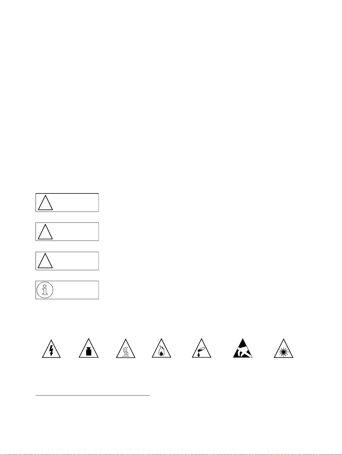
Safety symbols
Po tential so urces of da nger in this d escription are iden tified b y mean s of the f ol lowing symb ols:
Only
these
This symbol calls attention to a situation that could cause serious
Danger
!
Warning
!
Caution
!
Further symbols for defining the source of danger in greater detail1:
Electricity Weight Fire Chemicals
* Electrostatic discharge
injury or death to a person.
This symbol calls attention to a situation that could cause serious
injury to a person.
This symbol calls attention to a situation that could damage or
destroy hardware or software.
This symbol identifies useful informations.
Heat
ESD*
Laser
1. These symbols are not usually used in the manual. They’re an e xplanation of the symbols that can be depicted on the systems.
A31003-K16-X001-3-7620, 07/ 99
Hicom 100 E Version 2.1, Service manual
1-1
Page 19

Important Information
Safe ty information
1.1.1 Safet y infor m ati on : D an g er
Do not open the power supply. The device may only repaired by authorized personnel.
●
Opening the device and tampering with it can endanger your life.
Before applying power to the system or connecting extensions, ensure that the system is
●
correctly carthed.
Never operate the equipment with protective earthing conductor disconnected!
Voltages above 30 V AC (alternating current) or 60 V DC (direct current) are dangerous.
●
If the power cable appears to be damaged, replace it immediately.
●
Immediately replace any damaged safety equ ipment (covers , labels and protective cables).
●
If the maintenance work requires the power supply of the system to be shut down:
●
– Use the shut-off switch to disconnect the system from the powe r supply circuit, and se-
cure the shut-off device mechanically so that it cannot be used by other persons.
– Affix the information "DO NOT OPERATE" to the disconnect device.
A disconnect device can be a shut-off switch (main switch) or protective switch (fuse/
automatic cut out).
– Before starting any w ork on the installatio n, establi sh the location of the disco nnect de-
vice.
If you are performing work on circuits with hazardous voltages, always work together with
●
a partner who is familiar with the location of the switch for the power supply.
Always ensure adequate insulation when touching powered circuits.
●
Ensure that the installation is not powered by an additional power supply, or that it is pro-
●
tected via an additional fuse or an additional main switch.
Before starting any work, check whether the corresponding circuits are still on power . Nev-
●
er take it for g ranted that a ll circuits hav e reliab ly been disconn ected from the pow er supply
when a fuse or a main switch has been switched off.
During a thunderstorm, you should not connect or remove telephone lines and PCB
●
boards.
Expect to encounter leakage current from the telecommunication network.
●
Ensure that, whene ver work is carried out on an open installation, the installati on is never
●
left unsupervised.
1-2
A31003-K16-X001-3-7620, 07/99
Hicom 100 E Version 2.1, Service manual
Page 20

n
Important Information
Safety informatio
1.1.2 Safety information: Warn ing
There is the risk of an explosio n if the Nickel Cadm ium Batteryis not replaced correctly . T he
●
lithium battery must be replaced only by the same or equivalent types recommended by
the manufacturer.
Be aware of additional dangers with low voltages and large cross-sections. Cables with a
●
large cross-section ge nerall y hav e lo wer v ol tages, altho ugh the curr ent strengths ar e higher. This results in particular risks, e.g. in the event of short circuits.
When working on the i nstallations, nev er wear loose cloth ing and alwa ys tie bac k long hair .
●
Never wear jewellery, metal watch straps or for instance metal fittings and rivets on items
●
of clothing. There is a risk of injury and short circuit.
The surf ace of a m irror is conductive! N ev er touch p owered cir cuits with a m irror; you might
●
injure yourself and/or at least cause short-circuit damage.
Always wear the necessary eye protection whenever appropriate.
●
Always wear a protective helmet where falling objects might injure you.
●
Alwa ys disconnect the po wer sup ply when y ou are wo rking directly ne xt to a p ower su pply
●
unit or direct current converter, unless the work instructions expressly permit you to work
without having to shut off the power.
Never try to lift heavy objects without assistance.
●
In case of laser radiation: do not stare into the beam.
●
A31003-K16-X001-3-7620, 07/9 9
Hicom 100 E Version 2.1, Service manual
1-3
Page 21

Important Information
Safe ty information
1.1.3 Safety information: Caution
Check the set nominal voltage of the installation (operating instructions and type plate).
●
As long as the pow er supply is s witched on, alwa ys observe the gr eatest caution when per-
●
forming m easur emen ts on po w ered components and mainte nance work on plug-in car ds,
PC boards and covers.
To protect against the electrostatic discharge (ESD):
●
– Always wear the wristband before performing any work on PCB boards and modules.
– Only transport PC boards in suitable protective packaging.
– Alwa ys place P C board s on a gr ound ed cond ucting ba se, and do no t proce ss t he PC
boards anywhere else.
– Only use grounded soldering irons.
Only use tools and testers suitab le for the job . Do not use broke n tools and testers, inspe ct
●
them regularly.
Find out the location of the main switch for the power supply of the system. Follow the
●
appropriate instructions.
Install cables in such a way that they do not pose an accident risk (i.e. so that they do not
●
trip anybody up) and also so that they are not damaged.
1-4
A31003-K16-X001-3-7620, 07/99
Hicom 100 E Version 2.1, Service manual
Page 22

n
Important Information
Safety informatio
1.1.4 Gener al infor m at ion
If the installation is brought into the operating premises from a cold environment,
●
condensation may occur. Wait until the temperature of the installation has adjusted to the
ambient temperature and until the installation is absolutely dry before you start it up.
Before starting wall assembly, check whether the load-bearing capacity of the wall is
●
adequate, e.g. in the event of plasterboard walls.
When maintenance work has been comp leted, alwa ys re-install all saf ety equipment in the
●
right place.
Check your tools regularly. Only use intact tools.
●
Close the doors after test and maintenance work has been completed.
●
All cables and lines which leave a system cabinet must be screened at least between the
●
connection point in the cabine t and the point at which the cab l e lea ves the cabinet . Use a
clip and pressure screw to contact all screen fabric to the cabinet outlet. This is also
applicable for permanently connected service equipment.
Connect all cables only to the specified connection points.
●
Do not install any external modems in the installation cabinets.
●
Do not allow readily flammable materials to be stored near the installation or in the
●
installation room.
Ensure good lighting at the workplace.
●
Untidiness at the workplace involves the risk of injuries.
●
A31003-K16-X001-3-7620, 07/9 9
Hicom 100 E Version 2.1, Service manual
1-5
Page 23

Important Information
Safe ty information
1.1.5 Behaviour in emergencies
In the event of accidents, remain calm and considered.
●
Always switch off the power supply before you touch an accident victim.
●
If you are not able to immediately switch off the power supply, only touch the victim with
●
non-conducting materials (e .g. a broom handle ma de of wood ), and first o f all try to isolate
the victim from the power supply.
You must be familiar with first-aid principles in the event of electricity injuries. An urgent
●
need in such emergencies is fundamental knowledge of the various methods of
resuscitation if the victi m has stopped b reathing or if the victim ’s heart is no longer beating,
as well as first aid for treating burns.
If the victim is not breathing, immediately perform mouth-to-mouth or mouth-to-nose
●
resuscitation.
If you hav e appropria te training, imme diately perform heart massage if the victim’ s heart is
●
not beating.
Immediately ca ll an ambul ance or th e emer gency docto r . P rovide the f oll owing info rmation
●
in the following sequence:
– Where did the accident take place?
– What has happened?
– How many injured?
– What type of injuries?
– Wait for queries.
1.1.6 Accident reporting
Immediately r eport all accidents, "nea r a ccidents" and pote nti al so urces of dange r to your
●
manager.
Report all electrical shocks, no matter how small.
●
1-6
A31003-K16-X001-3-7620, 07/99
Hicom 100 E Version 2.1, Service manual
Page 24

y
Important Information
Data protection and data securit
1.2 Data protection and data security
This system also processes and uses personal data, e.g. for call charge metering purposes,
the displays and for recording user data.
In Germany, the processing and use of such personal data are subject to various regulations,
including the regulations of the Federal Data Protection Law (Bundesdatenschutzgesetz =
BDSG). For other countries, please follow the appropriate national laws.
The aim of data pro tection is t o protect the rights of individu als being aff ected b y use of his personal data.
In addition, the aim o f d ata pro tecti on is t o e nsure th at data ar e n ot corrupte d wh en proce ssed
and that one’s own interests and the interests of other parties which need to be protected are
not affected.
Members of Siemens and Siemens Rolm staff are required to observe business and data secrecy as a result of the company’s work rules.
In order to ensure that the statu tory requireme nts during service - whethe r duri ng "on -site service" or during "tele service" - are consistently met, you should always observe the following
rules. You will not only maintain the interests of you r/our customers, you will also av oid personal
consequences .
Contribute to maintain data protection and data security with your conscious action:
Ensure that only appropriately authorized persons have access to customer data.
●
Take full advantage of all options of allocating passwords; do not inform unauthorized
●
persons of passwords, e.g. by means of a written note.
Ensure that no unauthorized person is able to process (store, modify, transmit, disable,
●
delete) or use customer data in any way.
Prev ent unauthoriz ed persons from gaining access to data media, e.g. on backu p disks or
●
protocol printouts. This is applicable for service calls as well as for storage and transport.
Ensure that data media which are no longer required are completely destroyed. Ensure
●
that no papers remain generally available.
Work toget her with y our contacts of the customer: This crea tes mutual confid ence and reduce s
your own workload.
A31003-K16-X001-3-7620, 07/9 9
Hicom 100 E Version 2.1, Service manual
1-7
Page 25

Important Information
Data protection and data security
1-8
A31003-K16-X001-3-7620, 07/99
Hicom 100 E Version 2.1, Service manual
Page 26

n
System data
General system descriptio
2 System data
2.1 General system desc ription
The Hicom 108/112/118 systems belonging to the Hicom 100 E product family are compact,
digital, Euro-ISDN-com patib le telep hone system s suita b le for analogue and digital net work access and for analog ue and digi tal terminals. The basic configur ation of each system can be e xpanded and supplemented in different ways. See Figure 2-2 (Hicom 108), Figure 2-3 (Hicom
112), Figure 2-4 (Hicom 118).
The Hicom 108/112/11 8 systems are of flatpa ck design, i.e . without a backp lane. All basic func-
tions are incorporate d on the motherboard ( see Figure 3-4). Th e systems have plastic housin gs
consisting of base , intermediate secti on, a nd co v e r. The Hicom 118 h as an ad ditional int ermediate frame to accommodate system expansions. The housing sections are held together by
easily released latches.
The system expansions are of the plug-in type. The Hicom 108 has 1 slot (for analogue trunk
or S0 line modules), the Hicom 112 has 2 slots (for analogue trunk and S0 line modules), and
the Hicom 118 has 4 slots for further system expansions with line and subscriber modules.
The function expansions (optional) are attached with their own housings to the basic housing.
The pow er supply ( PSU/UP S) is also a ttached mech anicall y an d electrical ly to the b asic hous-
ing and is additionally secured by screws.
The integral main distribution frame is part of the basic housing. Plug-in connectors (terminal
blocks) render the line network easily separable from the system cards.
A31003-K16-X001-3-7620, 07/ 99
Hicom 100 E Version 2.1, Service manual
2-1
Page 27
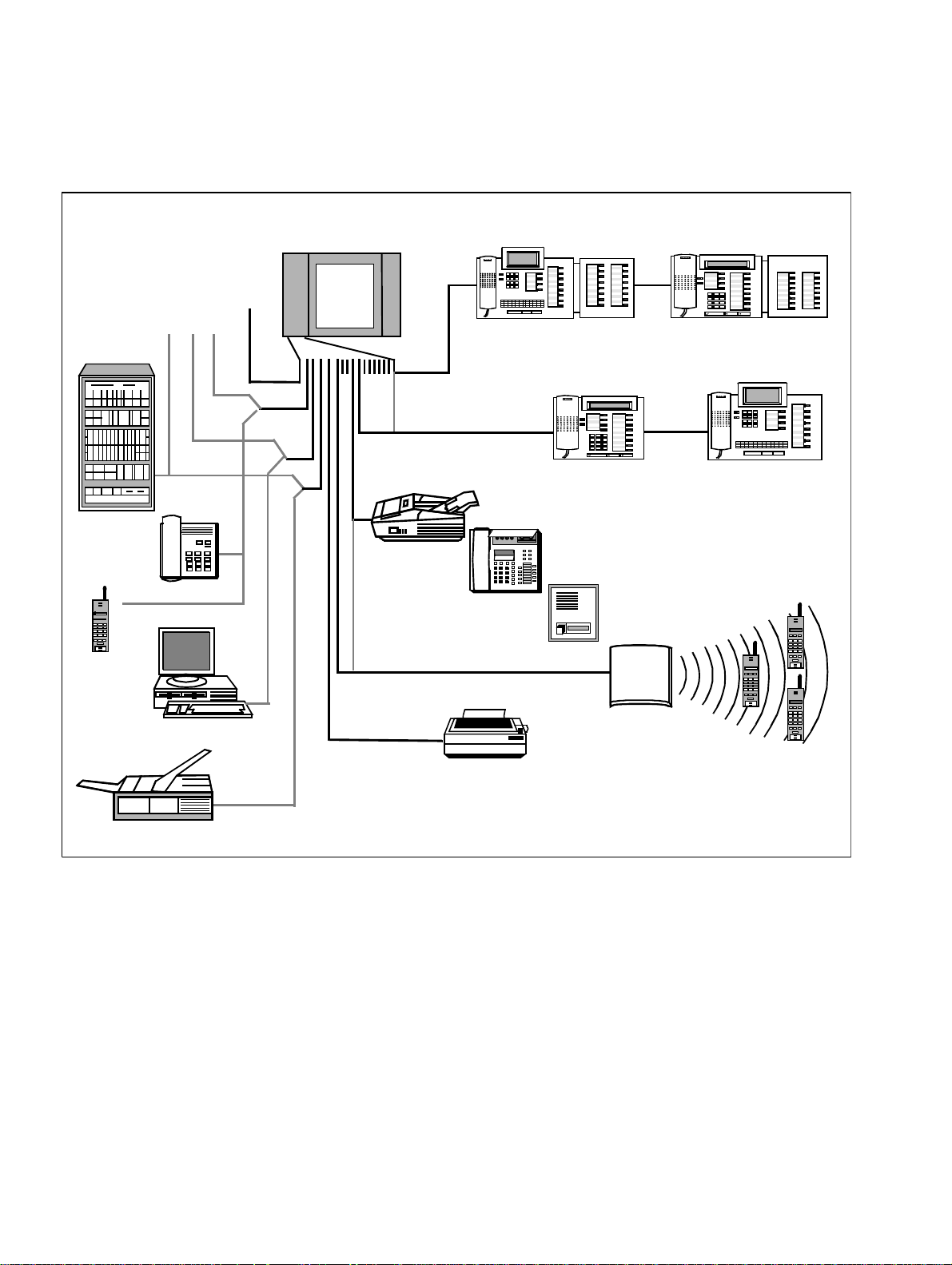
System data
Hardware overview
2.2 Hardware overv iew
Hicom 100 E
108
112
118
Hicom 300
Voice
terminal
Analogue
S
tnk./
0
extensions
tnk.
U
P0/E
Group 3 fax
ABCDEF
ABCDEF
123
MNOJKLGHI
MNOGHI
456
PQRSTUVWXYZ
PQRSTUV
789
0
0
optiset E memory with
optiset expansion
interface
optiset E advance plus
profise
N
N
N
N
optiset E advance plus
with optiset expansion
0
- optiset E entry
- optiset E advance
- optiset standard
t
- optiset memory
Entrance telephone
N
N
N
0
ABCDE F
ABC
123
DEF
MNO
GHI
JKL
MNOGHI
456
PQRSTUVWXYZ
PQRSTUV
789
0
0
optiset E memory
gigaset
megaset
gigaset i
Personal computer
V.24 interface
a/b interface
Call charge computer/PC
or printer
Group 4 fax
Figure 2-1 Connection options supported within system environment
2-2
A31003-K16-X001-3-7620, 07/99
Hicom 100 E Version 2.1, Service manual
Page 28

n
2.3 Documentation
Designation Item code number
Hicom 100 E Service Manual (German)
Hicom 100 E Service Manual (Dutch)
Hicom 100 E Service Manual (Italian)
Hicom 100 E Service Manual (Finnish)
Hicom 100 E Service Manual (English)
Hicom 100 E Service Manual (French)
Hicom 100 E Service Manual (Spanish)
Hicom 100 E Service Manual (Portuguese)
Hicom 100 E Electronic Service Manual P31003-K16-X001-*-20
Hicom 100 E Customer Datasheets A31003-K16-X-*-K6
A31003-K16-X-*-20 (up to SW 2.0.1+)
A31003-K16-X-*-5420
A31003-K16-X-*-7220
A31003-K16-X-*-7320
A31003-K16-X-*-7620
A31003-K16-X-*-7720
A31003-K16-X-*-7820
A31003-K16-X-*-7920
(up to SW 2.1)
German and other languages
German and other languages
System data
Documentatio
Service Instructions for
telephones, adapters, add-on units:
optiset E entry
optiset E basic
optiset E standard
optiset E advance
optiset E advance plus
optiset E memory
optiset E key module (add-on units)
optiset E analogue adapter
optiset E data adapter
optiset E ISDN adapter
optiset E phone adapter
optiset E acoustic adapter
optiset E distance adapter S
optiset E distance adapter M
User Manual (SW 2.0.1+):
System Support/Administration
User Manual (SW 2.0.2):
System Support/Administration
A31003-E8000-A100-*-20
German and other languages
(see above)
A31003-K3000-B341-*-19
German and other languages
(see above)
A31003-K16-B455-*-19
German and other languages
(see above)
Table 2-1 Documentation
A31003-K16-X001-3-7620, 07/9 9
Hicom 100 E Version 2.1, Service manual
2-3
Page 29

System data
System types
Designation Item code number
User Manual (SW 2.1)
System Support/Administration
A31003-K16-B546-*-19
German and other languages
(see above)
Table 2-1 Documentation
Documentation is available from your Dealer.
2.4 Sy stem types
The systems are available in the following configurations:
Hicom 108 with one slot, 2 U
Hicom 112 with two slots, 4 U
Hicom 118 with four slots, 6 U
and 4 a/b extension interfaces (see Figure 2-2)
P0/E
and 4 a/b extension interfaces (see Figure 2-3)
P0/E
and 4 a/b extension interfaces (see Figure 2-4)
P0/E
Nameplate on the housing base near the main distribution frame
A distinction is made between the following components:
Basic system, motherboard with V.24 interface via mini-DIN connector and optional EXM/
●
MPPI (external music on hold)
PSU1 power supply unit for Hicom 108 and 112 (see Section 3.8)
●
UPS1 uninterruptible power supply for Hicom 112 (see Section 3.8)
PSU2 power supply unit for Hicom 118 (see Section 3.8)
UPS2 uninterruptible power supply for Hicom 118 (see Section 3.8)
System expansions
●
The modular design permits almost any slot assignments (see Table 3-12).
SLAS subscriber line analogue with 4, 8 or 16 a/b interfaces
SLU 8 subscriber line U
P0/E
with 8 U
interfaces
P0/E
STLS subscriber/trunk line S0 with 4 S0 interfaces or 2 S0 interfaces
TLA trunk line analogue with 2, 4 or 8 analogue trunk interfaces
Function expansions (see Section 3.6)
●
ALUM power failure transfer with 4 transfer options for analogue lines
Fax/DDI with announcement (DTMF)
GEE call-charge pulse recognition for 4 analogue trunk interfaces
SIB serial interface board (optional V.24 interface)
STRB control relay module with 4 control inputs and 4 control outputs
STBG4 current limiting module for France
WS48/ÜFS analogue DDI trunk for Austria
EXM/MPPI - module for MOH
2-4
A31003-K16-X001-3-7620, 07/99
Hicom 100 E Version 2.1, Service manual
Page 30
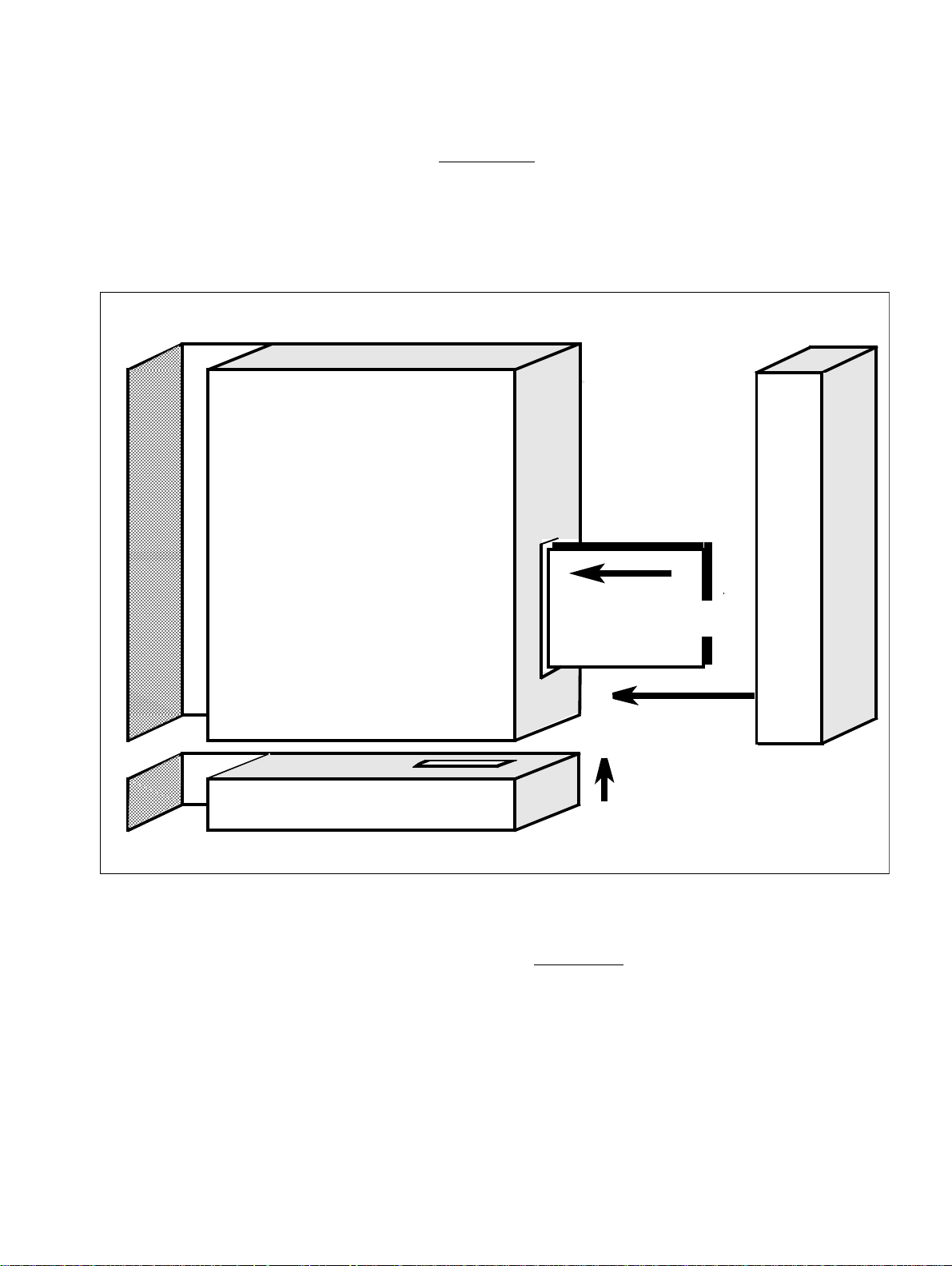
w
System data
Hicom 108 system overvie
The MDF (main distribution frame) (see Section 3.9) expands automatically with the system,
since each expansion provides the necessary interfaces. Any space that may be required for
future function expansions must be taken into account in the initial plans.
2.5 Hicom 108 system overview
Cover/MDF
PSU1Basic system
System expansion
Hicom 108
1 ... 4
Plug in
Function expansions
Figure 2-2 Hicom 108 structural concept
Slot 1 for system expansions
:
Analogue (TLA2) or S0 (STLS2) trunk module (see Table 3-12)
1
Plug in and
secure (scr ew)
A31003-K16-X001-3-7620, 07/9 9
Hicom 100 E Version 2.1, Service manual
2-5
Page 31

System data
Hicom 112 system overview
2.6 Hicom 112 system overview
Cover/MDF
Basic system
PSU1/UPS1
System expan sion
3
System expansion
Hicom 112
1... 4
Function expansions
Figure 2-3 Hicom 112 structural concept
Slots 1 and 3 fo r system expansions
:
Freely assignable with line modules (see Table 3-12)
1
Plug in and
secure (screw)
Plug in
2-6
A31003-K16-X001-3-7620, 07/99
Hicom 100 E Version 2.1, Service manual
Page 32

w
2.7 Hicom 118 system overview
Cover/MDF
Basic system
Hicom 118 system overvie
System expansion
4
System data
PSU2/UPS2
3
Hicom 118
1
2
3
4
System expansion
2
Plug in and
secure (screw)
Plug in
1
Function expansions
Figure 2-4 Hicom 118 structural concept
Slots 1 to 4 for system extensions
:
Freely assignable with line and/or subscriber modules (see Table 3-12)
A31003-K16-X001-3-7620, 07/9 9
Hicom 100 E Version 2.1, Service manual
2-7
Page 33

T
System data
echnical data
2.8 Technical data
System Width Height Depth
Hicom 108 basic configuration 470 370 80
Hicom 108 with max. expansions 470 630 80
Hicom 112 basic configuration 470 370 80
Hicom 112 with max. expansions 470 630 80
Hicom 118 basic configuration 470 370 110
Hicom 118 with max. expansions 470 630 110
Table 2-2 System dimensions in mm
200
470
300
Basic housingMDF
PSU
370
(UPS)
Module (max. 4)
300
Module
Figure 2-5 System dimensions and minimum clearances
Dimensions
in mm
A31003-K16-X001-3-7620, 07/99
2-8
Hicom 100 E Version 2.1, Service manual
Page 34

a
System data
Technical dat
Terminal interfaces Range in m
ISDN S0 point-to-point connection < 600
ISDN S0 point-to-multipoint connection < 150
ISDN S0 terminal box to terminal < 10
a/b extensions < 2000
U
console to master < 1000
P0/E
U
master to slave < 100
P0/E
Table 2-3 Ranges (with J-Y(ST) 2x2x0.6) for term inal interfaces
Operation Transport Storage
Ambient temperature in °C +5 to +40 -40 to +70 -5 to +45
Relative humidity in % 85 95 95
Table 2-4 Climatic conditions
Caution
!
Do not expose to direct sunlight and keep appliance away from heaters to avoid of
the danger of localised overheating.
If condensation forms, allow the appliance to dry before operation.
It is essential to ensure that condensation cannot form while the appliance is in operation.
A31003-K16-X001-3-7620, 07/9 9
Hicom 100 E Version 2.1, Service manual
2-9
Page 35

System data
Basic configuration and system expansions
2.9 Basic configuration and system expansions
Hicom 108 Hicom 112 Hicom 118
U
interfaces - MB 2 4 6
P0/E
a/b interfaces - MB 4 4 4
Slots for expansions 1 2 4
Table 2-5 Basic configuration and system expansions
2.10 System interfaces
Trunk interface with analogue trunk
DTMF, DP without earth recall
●
Tone detector (dial-tone interpreter) for automatic dialling
●
Analogue pseudo direct dialling in using DTMF signalling with announcement (DDI option)
●
Call-charge pulse recognition per trunk (GEE option)
●
Fax opt ion
●
Mixed f ax/D DI oper ation (opt ion)
●
Trunk interface with direct dialling in for Austria
WS48 and ÜFS methods
●
Trunk interface and extension interface S
System synchronisation to trunk clock with selection circuit
●
0
Extension interface for normal telephone
Bilingual: DP or DTMF (12-key keyboard)
●
Range 2000 m using cable with 0.6 mm dia
●
Flash detection with DTMF
●
One or more entrance telephone adaptors can be connected
●
Extension interface for U
Only in-house cabling permitted
●
2-10
P0/E
A31003-K16-X001-3-7620, 07/99
Hicom 100 E Version 2.1, Service manual
Page 36

s
Table of item code number
3 Overview of modules
3.1 Table of item code numbers
Modul e/comp onent Item code number Remarks
MB 6/4
MB 4/4
MB 2/4
MB 6/4
MB 4/4
MB 2/4
MB 6/4
MB 4/4
MB 2/4
MB 6/4
MB 4/4
S30817-Q920-A501
S30817-Q920-B501
S30817-Q920-C501
S30817-Q920-A601
S30817-Q920-B601
S30817-Q920-C601
S30817-Q920-A701
S30817-Q920-B701
S30817-Q920-C701
S30817-Q920-A711
S30817-Q920-B711
SW 2.0.1+
SW 2.0.2
SW 2.1
POR
Overview of modules
MB 6/4 S30817-Q920-K701 Hicom 118-2 (two-box system)
EB118-2 S30817-Q952-A601 Expansion module for Hicom 118-2
MB 2/4 S30817-Q920-H601 Hicom 108 NDL
SLAS16
SLAS8
SLAS4
S30817-Q925-A301
S30817-Q921-C301
S30817-Q921-D301
SLU8 S30817-Q922-A301
STLS4
STLS2
S30817-Q924-A313
S30817-Q924-B313
TLA8 S30817-Q926-A301 GER, CHN, AUS, CIS , CRE, LUX, FIN,
AST
S30817-Q926- A308 GBR,IND
S30817-Q926- A311 POR
S30817-Q926- A312 SP A
S30817-Q926-A314 BEL,IM, IRL, ITL, POL, TRK
S30817-Q926-A315 NDL
S30817-Q926-A316 FRA
Table 3-1 Item code numbers with national versions
A31003-K16-X001-3-7620, 07/ 99
Hicom 100 E Version 2.1, Service manual
3-1
Page 37

T
Overview of modules
able of item code numbers
Module/component Item code number Remarks
TLA4 S30817-Q923-A308 GBR,IND, RSA
S30817-Q923-A311 POR
S30817-Q923-A312 SPA
S30817-Q923-A313 GER, CHN, FIN, AUS
S30817-Q923-A314 ARG, BEL, DEN, GRE, IDS, IM, ITL,
MAL, PHI, POL , CIS, SIN, SWZ, THA,
HNG
S30817-Q923-A315 BRA, NDL
S30817-Q923-A316 FRA
TLA2 S30817-Q923-B308 GBR, IND, RSA
S30817-Q923-B311 POR
S30817-Q923-B312 SPA
S30817-Q923-B313 GER, CHN, FIN, AUS
S30817-Q923-B314 ARG, BEL, DEN, GRE, IDS, IM, ITL,
MAL, PHI, POL, POR, CIS, SIN, SW Z,
THA, HNG
S30817-Q923-B315 BRA, NDL
S30817-Q923-B316 FRA
GEE16 S30817-Q951-A313 BEL, GER, IM, LUX, CIS, HNG
S30817-Q951-A317 FIN, RSA
GEE12 S30817-Q931 -A301 FRA, IDS , IM, IRL, MAL, PH I, CIS, SIN,
SWZ, THA, HNG
S30817-Q931-A302 AUS
S30817-Q931-A311 POR
S30817-Q931-A312 SPA
S30817-Q931-A314 ITL
GEE50 S30817-Q931-B315 FRA, GBR, NDL
SIB S30122-K5685-X
STRB S30817-Q932-A
Fax/DDI S30817-Q933-A301
STBG4 S30817-Q934-A FRA
ALUM4 S30817-Q935-A
Door opener S30817-Q930-A100 As of 04/96: S30817-Q930-A200
TFE/V S30817-Q936-A313
Table 3-1 Item code numbers with national versions
A31003-K16-X001-3-7620, 07/99
3-2
Hicom 100 E Version 2.1, Service manual
Page 38

s
Overview of modules
Table of item code number
Modul e/comp onent Item code number Remarks
EXM S30817-H902-A401 Without coding, with screw terminals
S30817-H902-B401 With coding, without screw terminals
MPPI S30122-H5380-X
OPA (options adapter) S30122-K55 25-X
PSU1 S30122-K54 48-X 312
PSU2 S30122-K54 49-X 312
UPS1 S30122-K54 50-X 312
UPS2 S30122-K54 51-X 312
Battery box S30122-K5403-X
V.24 adapter cable S30122-X5468-X MB only
V.24 adapter cable C39195-Z7267-C5 SIB only
V.24 printer adapter S30122-K 55 97-X
V.24 adapter modem S30122-K55 97-X 100
108/112 ribbon cable C39195-A7001-B83 MB <-> system expansions
118 ribbon cable C39195-A7018-B82 MB <-> system expansions
Plug connector C39334-Z7089-C14 4-pin
Plug connector C39334-Z7089-C13 8-pin
EXM/MPPI cable C39195-A7001-B88 Uncoded
EXM/MPPI cable C39195-A7001-B111 Coded
GEE cable C39165-A7001- B87 Uncoded
GEE cable C39165-A7001- B110 Coded
PSU connecting cable C39195-A7001-B85 Up to SW 2.0.1+
PSU connecting cable C39195-A7001-B112 As of SW 2.0.2
Table 3-1 Item code numbers with national versions
Abbrev. Country Abbrev. Country
ARG Argentina IND India
AST Australia IRL Ireland
AUS Austria ITL Italy
BEL Belgium LUX Luxembourg
BRA Brazil MAL Malaysia
CHN China NDL Netherlands
Table 3-2 Country codes
A31003-K16-X001-3-7620, 07/9 9
Hicom 100 E Version 2.1, Service manual
3-3
Page 39

T
Overview of modules
able of item code numbers
Abbrev. Country Abbrev. Country
CIS Commonwealth of Independent
NOR Norway
States
CRE Czech Republic PHI Philippines
DEN Denmark POL Pol an d
FIN Finland POR Portugal
FRA France RSA Republic of South Africa
GBR Great Britain SIN Singapore
GER Germany SPA Spain
GRE Greece SWD Sweden
HNG Hungary SWZ Switzerland
IDS Indonesia THA Thailand
IM International Markets TRK Turkey
Table 3-2 Country codes
A31003-K16-X001-3-7620, 07/99
3-4
Hicom 100 E Version 2.1, Service manual
Page 40

s
3.2 Overview of configurations
MDF side
Slot 4
Slot 3
Overview of modules
Overview of configuration
Ribbon cable
MB
Ribbon cable colour coding (red)
Slot 2
PSU/UPS side
Slot 1
Ribbon cable
Ribbon cable colour coding (red)
Max. 4 function expansions
Figure 3-1 System expansions - slot numbers
The overview shows the variety of possible combinations for the systems (see also Section
3.5).
Hicom 108 has one slot that is used only f or line modules (analo gue trunk or So). A combi nation
of ISDN and analogue trunk connections is not possible.
Hicom 112 h as tw o slots that are used for line modules (analog ue t runk, So). A combination of
ISDN and analogue trunk connections is possible.
A31003-K16-X001-3-7620, 07/9 9
Hicom 100 E Version 2.1, Service manual
3-5
Page 41

Overview of modules
Standard extension number plans
Hicom 118 has four slots for continuing system expansion with line modules and/or extension
modules. A combination of ISDN and analogue trunk connections is possible.
System System expansions Function expansions
Hicom 108 1 > slot 1 4
Hicom 112 2 > slots 1 and 3 4
Hicom 118 4 > slots 1 to 4 4
Table 3-3 Possible expansions
3.3 Sta ndard extensi on num ber plans
3.3.1 Standard numbering of the MB modules
Hicom
108
MB
U
P0/E
a/b
Ext. no. Int. ext.
no.
DDI no. Port
numbering
11 11 11 1 U
12 12 12 2 U
17 17 17 1 U
18 18 18 2 U
23 23 23 1 a/b
24 24 24 2 a/b
25 25 25 3 a/b
26 26 26 4 a/b
Type
MU
P0/E
M
P0/E
S U
P0/E
S
P0/E
P0/E
P0/E
master
slave
Table 3-4 Standard numbering, MB 2/4 Hicom 108 (SW 2.0.1)
Hicom
108
MB
U
P0/E
Ext. no. Int. ext.
no.
DDI no. Port
numbering
11 11 11 1 U
12 12 12 2 U
13 13 13 1 U
14 14 14 2 U
Type
MU
P0/E
M
P0/E
S U
P0/E
S
P0/E
15 15 15 1 a/b
a/b
16 16 16 2 a/b
17 17 17 3 a/b
18 18 18 4 a/b
Table 3-5 Standard numbering, MB 2/4 Hicom 108 (as of SW 2.0.1+)
A31003-K16-X001-3-7620, 07/99
3-6
Hicom 100 E Version 2.1, Service manual
P0/E
P0/E
master
slave
Page 42

s
Standard extension number plan
Hicom
112
MB
U
P0/E
Ext. no. Int. ext.
no.
DDI no. Port
numbering
11 11 11 1 U
12 12 12 2 U
13 13 13 3 U
14 14 14 4 U
17 17 17 1 U
18 18 18 2 U
19 19 19 3 U
20 20 20 4 U
Type
P0/E
P0/E
P0/E
P0/E
P0/E
P0/E
P0/E
P0/E
23 23 23 1 a/b
a/b
24 24 24 2 a/b
25 25 25 3 a/b
26 26 26 4 a/b
Table 3-6 Standard numbering, MB 4/4 Hicom 112 (SW 2.0.1)
Overview of modules
MU
P0/E
master
M
M
M
S U
P0/E
slave
S
S
S
Hicom
112
MB
U
P0/E
Ext. no. Int. ext.
no.
DDI no. Port
numbering
11 11 11 1 U
12 12 12 2 U
13 13 13 3 U
14 14 14 4 U
15 15 15 1 U
16 16 16 2 U
17 17 17 3 U
18 18 18 4 U
Type
MU
P0/E
M
P0/E
M
P0/E
M
P0/E
S U
P0/E
S
P0/E
S
P0/E
S
P0/E
19 19 19 1 a/b
a/b
20 20 20 2 a/b
21 21 21 3 a/b
22 22 22 4 a/b
Table 3-7 Standard numbering, MB 4/4 Hicom 112 (as of SW 2.0.1+)
P0/E
P0/E
master
slave
A31003-K16-X001-3-7620, 07/9 9
Hicom 100 E Version 2.1, Service manual
3-7
Page 43

Overview of modules
Standard extension number plans
Hicom
118
Ext. no. Int. ext.
no.
11 11 11 1 U
12 12 12 2 U
13 13 13 3 U
MB
14 14 14 4 U
15 15 15 5 U
16 16 16 6 U
U
P0/E
17 17 17 1 U
18 18 18 2 U
19 19 19 3 U
20 20 20 4 U
21 21 21 5 U
22 22 22 6 U
23 23 23 1 a/b
a/b
24 24 24 2 a/b
25 25 25 3 a/b
26 26 26 4 a/b
DDI no. Port
numberin
g
Type
MU
P0/E
M
P0/E
M
P0/E
M
P0/E
M
P0/E
M
P0/E
S U
P0/E
S
P0/E
S
P0/E
S
P0/E
S
P0/E
S
P0/E
P0/E
P0/E
master
slave
Table 3-8 Standard numbering, MB 6/4 Hicom 118 (as of SW 2.0.1+)
3-8
A31003-K16-X001-3-7620, 07/99
Hicom 100 E Version 2.1, Service manual
Page 44

s
Overview of modules
Standard extension number plan
3.3.2 Extension number plans of th e add- on modules
The extension number plans of the add-on modules have been changed relative to that of
SW 2.0.1. The ne w assignment of the e xtension numbers an d line numbe rs ensures co nsistent
numbering at all times whenever the system is expanded. Attention must be paid to the new
equipping sequence for extension and trunk modules.
Extension module
Trunk module
Slot 2
Slot 1
MB
View from the PSU side
Slot 4
Slot 3
Figure 3-2 Equipping sequence for extension and trunk modules
The structure of the e xtension numb er plans is described in more detail in C hapter 5,
Installation of the Service Manual (see Section 5.5).
A31003-K16-X001-3-7620, 07/9 9
Hicom 100 E Version 2.1, Service manual
3-9
Page 45

Overview of modules
Main module - motherboard
3.4 Main module - motherboard
The MB 6/4 motherboard is the main board and accommodates 6 digital extension interfaces
(U
an integrated digital mod em, the signalling unit (SIU), a real-time clock with NC battery, and a
PCM highway controller and conference circuit.
Hicom 108 MB 2/4 - motherboard with 2 x U
Hicom 112 MB 4/4 - motherboard with 4 x U
Hicom 118 MB 6/4 - motherboard with 6 x U
An EXM or MPPI module can be con nected to the MB f o r external music on h old. Th e mo dul e
also has a V.24 interface with a mini-DIN connector that can be used for outputting or editing
call charge data or customer data. Teleservice is possible via both the V.24 interface and the
digital modem (in connection with a digital trunk of the STLS module).
U
moved from the module for installation or maintenance purposes.
), 4 an alogue extension interfaces (a /b), the V.24 interface (SIC – serial interface cab le),
P0/E
, 4 x a/b (see Table 3-9)
P0/E
, 4 x a/b (see Table 3-10)
P0/E
, 4 x a/b (see Table 3-11)
P0/E
/ a/b extensions ar e connect ed by means of scre w terminals . These terminals can be re-
P0/E
MDF side
U
ports
P0/E
1...6
SIC
V.24 adapter
a/b ports
1...4
EXM / MPPI
1
4
5
12
1
8
1
10
X1
X2
X10
X11
X3
X4
MB
Not assigned for MB2/4
9 -12 not assigned
for MB4/4
GND
PSU/UPS
Plug connector as
of SW 2.0.2
PSU/UPS side
3 and 4
System
expansion
1 and 2
Options bus
Figure 3-3 Motherboard interfaces (SW 2.0.1+)
3-10
A31003-K16-X001-3-7620, 07/99
Hicom 100 E Version 2.1, Service manual
Page 46

d
MDF side
U
ports
P0/E
1...6
Switching network
expansion
for expansion
board
SIC
V. 24 adapter
1
X1
4
5
X2
Not assigned for MB2/4
9–12 not assigned
12
for MB4 /4
X12 advance provisioning
X10
X11
GND
MB
Main module - motherboar
PSU/UPS
Plug connector as
of SW 2.0.2
Overview of modules
PSU/UPS side
3 and 4
System
expansion
1
a/b ports
1...4
X3
8
1
EXM / MPPI
X4
10
Options bus
Figure 3-4 Motherboard interfaces (as of SW 2.0.2)
1 and 2
A31003-K16-X001-3-7620, 07/9 9
Hicom 100 E Version 2.1, Service manual
3-11
Page 47

Overview of modules
Main module - motherboard
Contact Port X1 Port X2 Port X3 Port X 4
1a1 - port 1 a 1 - port 1 GND
2b1 - port 1 b 1 - port 1 not assigned
3a2 - port 2 a 2 - port 2 not assigned
4b2 - port 2 b 2 - port 2 EXMCL
5 a 3 - port 3 EXMDIR
6 b 3 - port 3 HRES
7 a 4 - port 4 EXMD
8 b 4 - port 4 EXMDET
9 +5V
10 not assigned
11
12
Table 3-9 Contact assignment of the MB interfaces 2/4 Hicom 108
Contact Port X1 Port X2 Port X3 Port X 4
1a1 - port 1 a 1 - port 1 GND
2b1 - port 1 b 1 - port 1 not assigned
3a2 - port 2 a 2 - port 2 not assigned
4b2 - port 2 b 2 - port 2 EXMCL
5 a3 - port 3 a 3 - port 3 EXMDIR
6 b3 - port 3 b 3 - port 3 HRES
7 a4 - port 4 a 4 - port 4 EXMD
8 b4 - port 4 b 4 - port 4 EXMDET
9 +5V
10 not assigned
11
12
Table 3-10 Contact assignment of the MB interfaces 4/4 Hicom 112
Contact Port X1 Port X2 Port X3 Port X 4
1a1 - port 1 a 1 - port 1 GND
2b1 - port 1 b 1 - port 1 not assigned
3a2 - port 2 a 2 - port 2 not assigned
4b2 - port 2 b 2 - port 2 EXMCL
5 a3 - port 3 a 3 - port 3 EXMDIR
6 b3 - port 3 b 3 - port 3 HRES
7 a4 - port 4 a 4 - port 4 EXMD
8 b4 - port 4 b 4 - port 4 EXMDET
9 a5 - port 5 +5V
10 b5 - port 5 not assigned
Table 3-11 Contact assignment of the MB interfaces 6/4 Hicom 118
A31003-K16-X001-3-7620, 07/99
3-12
Hicom 100 E Version 2.1, Service manual
Page 48

s
Overview of modules
Add-on modules for system expansion
Contact Port X1 Port X2 Port X3 Port X4
11 a6 - port 6
12 b6 - port 6
Table 3-11 Contact assignment of the MB interfaces 6/4 Hicom 118
3.5 Add-on modules for system expansions
The Hicom 108 has one slot for the TLA2 (analogue trunk) or STLS2 (So) module.
The Hicom 112 has two slots (1 and 3) for system expansions.
The Hicom 118 has 4 slot s for expanded system config ur ations . T he m odules ca n be in serted
in any of these slots. Refer to the relevant module descriptions for details of any restrictions.
Subsequent expansions carried out on the Hicom 118 should be installed following the new
equipping sequence for extension and trunk modules.
If slot 1 is assigned with an SLU8 (U
deactivated.
extension) or an SLAS16 (a/b extensions), slot 2 is
P0/E
Module Hicom 108 Hicom 108
Hicom 112 Hicom 118 Hicom 118-2*
NDL
slot
SLAS16 -- -- 1, 3 3, 4 3, 4, 6, 7, 8
SLAS8 -- 3 -- 1 - 4 1 - 8
SLAS4 -- -- -- 1 - 4 1 - 8
SLU8 -- -- -- 3, 4 3, 4
STLS4 -- -- 1, 3 1 - 4 1, 2, 3, 4
STLS2 1 -- 1, 3 1 - 4 1, 2, 3, 4
TLA8 -- -- 1, 3 1 - 4 1 - 8
TLA4 -- 1 1, 3 1 - 4 1 - 8
TLA2 1 1 1, 3 1 - 4 1 - 8
*= see Section 12.3.2
Table 3-12 Add-on modules for system expansions
The abov e table only shows the possib le slots. It does not illustr ate the maximum configurati on
possible or authorization-related restrictions.
Only SLAS8 modules can be inserted in slots 1 and 2. SLU modules must not be
inserted in slot 1.
A31003-K16-X001-3-7620, 07/9 9
Hicom 100 E Version 2.1, Service manual
3-13
Page 49

A
Overview of modules
dd-on modules for system expansions
For Hicom 108, module cutover is dependent on the system code, i.e. unauthorised
modules are detected and are not put into operation.
3-14
A31003-K16-X001-3-7620, 07/99
Hicom 100 E Version 2.1, Service manual
Page 50

s
Overview of modules
Add-on modules for system expansion
3.5.1 SLAS8/4 (subscriber line analogue)
The SLAS8/4 subscriber line module for 8/4 analogue a/b interfaces is used for connecting
standard telepho nes and for additional devices (such as group 3 fax machines and door open er
adapters) (see Section 5.13).
X1
50
to MB
2
a/b ports 1-4
a/b ports 5-8
not for SLAS4
1
X2
8
1
SLAS
X3
8
Figure 3-5 SLAS interfaces
Contact X2 (a/b ports 1-4) X3 (a/b ports 5-8)
1a 1 a 5
2b 1 b 5
3a 2 a 6
4b 2 b 6
5a 3 a 7
6b 3 b 7
7a 4 a 8
8b 4 b 8
Table 3-13 Contact assignment of the SLAS interfaces
A31003-K16-X001-3-7620, 07/9 9
Hicom 100 E Version 2.1, Service manual
3-15
Page 51

A
Overview of modules
dd-on modules for system expansions
3.5.2 SLAS16 (subscriber line analogue)
The SLAS16 subscri ber line m odule for 16 analog ue a/b i nterf aces is u sed f or connecting sta ndard telephones and for additional devices (such as group 3 fax machines and door opener
adapters) (see Section 5.13).
1
a/b ports 1-4
a/b ports 5-8
a/b ports 5-8
X2
8
50
1
X3
8
1
SLAS16
X4
X1
2
to MB
8
1
a/b ports 5-8
X5
8
Figure 3-6 SLAS interfaces
Contact X2 (a/b ports 1-4) X3 (a/b ports 5-8) X4 (a/b ports 9-12) X5 (a/b ports 13-16)
1a 1a 5a 9a 13
2b 1b 5b 9b 13
3 a 2 a 6 a 10 a 14
4 b 2 b 6 b 10 b 14
5 a 3 a 7 a 11 a 15
6 b 3 b 7 b 11 b 15
7 a 4 a 8 a 12 a 16
8 b 4 b 8 b 12 b 16
Table 3-14 Contact assignment of the SLAS interfaces
3-16
A31003-K16-X001-3-7620, 07/99
Hicom 100 E Version 2.1, Service manual
Page 52

s
Overview of modules
Add-on modules for system expansion
3.5.3 SLU8 (subscriber line U
P0/E
)
The SLU8 module with 8 digital extension interfaces permits the connection of up to 16 digital
terminals in master/sla ve con figuration s. A combin ation of Optiset an d Optiset E is not possible
in master/slave configuration.
50
1
X2
U
ports
P0/E
1-4
8
SLU8
X1
to MB
1
U
ports
P0/E
5-8
X3
8
2
Figure 3-7 SLU8 interfaces
Caution
!
After the power supply has been disconnected, at least 2 minutes must elapse
before the SLU can be removed or plugged in.
Failure to adhere to this requirement could result in damage to the MB.
Slot 2 is deactivated if the SLU8 or SLAS16 card is plugged into slot 1.
Contact X2 (U
Po/E
1a 1 a 5
2b 1 b 5
3a 2 a 6
4b 2 b 6
5a 3 a 7
6b 3 b 7
7a 4 a 8
8b 4 b 8
ports 1-4) X3 (U
ports 5-8)
P0/E
Table 3-15 Contact assignment of the SLU interfaces
A31003-K16-X001-3-7620, 07/9 9
Hicom 100 E Version 2.1, Service manual
3-17
Page 53

A
Overview of modules
dd-on modules for system expansions
3.5.4 STLS (subscriber trunk line S0)
The STLS4 mod ule has 4 S0 ports. The ports can be operated either a s ex ternal trunk interf aces in subscriber unit mode or as an internal S0 interface (PMP bus) in network terminal (NT)
mode (with cross-connected RX TX lines) (see Figure 5-6).
STLS2 is a subequipped version with 2 S0 ports.
This module is also required for using the digital modem in the MB.
provision is made for supplying power to mains-powered terminal devices.
No
Devices of this type must be powered locally, e.g. using a plug-in mains adapter or
bus PSU.
50
S0 ports
1
Mini Western
2
X2
not for STLS2
3
4
Figure 3-8 STLS interfaces
6 5 4 3 2 1
STLS
2 = SX +
3 = SR +
4 = SR 5 = SX -
SX = signal transmit
SR = signal receive
X1
to MB
2
Figure 3-9 Contact assignment of the S0 Mini Western socket
3-18
Hicom 100 E Version 2.1, Service manual
A31003-K16-X001-3-7620, 07/99
Page 54

s
Overview of modules
Add-on modules for system expansion
3.5.5 TLA 4/2 (trunk line analogue)
The TLA 4/2 is an MSI module with 4/2 analogue trunk lines for dial pulsing (DP) and DTMF
signalling methods.
a/b ports
MSI 1 - 4
to trunk
to GEE
module
1
X2
8
1
X3 (not assigned)
8
1
X4
10
50
TLA 4/2
to MB
X1
2
Figure 3-10 TLA 4/2 interfaces
Contact Port X2 Port X4
1 a trunk 1 GND with GEE50 FRA,
otherwise not assigned
2 b trunk 1 b trunk 1
3 a trunk 2 a trunk 1
4 b trunk 2 b trunk 2
5 a trunk 3 a trunk 2
6 b trunk 3 b trunk 3
7 a trunk 4 a trunk 3
8 b trunk 4 b trunk 4
9 a trunk 4
10 Call charging module assignment
Trunks 1 and 2 only with TLA2
Table 3-16 Contact assignment of the TLA 4/2 interfaces
A31003-K16-X001-3-7620, 07/9 9
Hicom 100 E Version 2.1, Service manual
3-19
Page 55

A
Overview of modules
dd-on modules for system expansions
3.5.6 TLA 8 (trunk line analogue)
The TLA 8 is an MSI module with 8 analogue trunk lines for dial pulsing (DP) and DTMF signalling methods.
1
10
1
8
1
8
X3
X2
X4
TLA 8
X1
50
to MB
2
to GEE
module
a/b ports
MSI 1–4
to trunk
a/b ports
MSI 5–8
to trunk
1
to GEE
module
X5
10
Figure 3-11 TLA 8 interfaces
Contact Port X3 Port X2 Port X4 Port X5
1 GND a trunk 1 a trunk 5 GND
2 b trunk 1 b trunk 1 b trunk 5 b trunk 5
3 a trunk 1 a trunk 2 a trunk 6 a trunk 5
4 b trunk 2 b trunk 2 b trunk 6 b trunk 6
5 a trunk 2 a trunk 3 a trunk 7 a trunk 6
6 b trunk 3 b trunk 3 b trunk 7 b trunk 7
7 a trunk 3 a trunk 4 a trunk 8 a trunk 7
8 b trunk 4 b trunk 4 b trunk 8 b trunk 8
9 a trunk 4 a trunk 8
10 GMZ 1 GMZ 2
GMZ= Call charging module assignment
GND = GND with GEE50 FRA, otherwise not assigned
Table 3-17 Conta ct assignment of the TLA 8 interfaces
3-20
A31003-K16-X001-3-7620, 07/99
Hicom 100 E Version 2.1, Service manual
Page 56

s
Overview of modules
Function expansions with options bu
3.6 Function expansions with options bus
Function expansions can be connected to the O-bus (options bus) interface as required. No
major hardware adaptations are necessary. The central processor recognises the connected
modules when the system is booted and supplie s them with the requisite para meters f or initialisation. All modules are of the plug-in type. Up to four of a given module can be inserted (exception: only one STRB), or different modules can be combined as required.
3.6.1 Opt ion s ad ap te r
The options b us adapter (OPA) is a mechanical and el ectrical adapter bet ween the first options
module and the system motherboard.
3.6.2 GEE module
There are 4 ca ll mete ring rece iv ers in each of th e mo dules li ste d be low. These receiv er s reg ister the call charge pulses and perform initial processing functions:
Module Frequency Configurable for
GEE 12 12kHz ITL, POR, SWZ, SPA, IM, FRA, AUS
GEE 16 16kHz BEL, GER without blocking circuit
GEE 16 16kHz FIN, RSA with blocking circuit
GEE 50 50Hz NDL, GBR
Table 3-18 GEE module, national versions
The channel f or cal l charge r ecognition i s looped i nto the trunk and t hen routed t o the TLA.
●
.
MB side
1
1
10
X1
to TLA
X3
X5
10
to trunk
MSI
1
X4
8
GEE module
X2
Figure 3-12 GEE module, interfaces
A31003-K16-X001-3-7620, 07/9 9
Hicom 100 E Version 2.1, Service manual
Module side
3-21
Page 57

Overview of modules
Function expansions with options bus
Contact Port X3 Port X4 Port X5
1 a GND * Trunk 1 (AL1) 0V
2 b Trunk 1 (BN 1) Trunk 1 (BL1) 0V
3 a Trunk 1 (AN 1) Trunk 2 (AL2) RTS
4 b Trunk 2 (BN 2) Trunk 2 (BL2) CTS
5 a Trunk 2 (AN 2) Trunk 3 (AL3) RXD
6 b Trunk 3 (BN 3) Trunk 3 (BL3) TXD
7 a Trunk 3 (AN 3) Trunk 4 (AL4) 0V
8 b Trunk 4 (BN 4) Trunk 4 (BL4) +5V
9 a Trunk 4 (AN 4) 0V
10 Call charging module
assignment
* in the case of GEE 50 FRA (otherwise not assigned)
Table 3-19 Contact assignment of the GEE module
+5V
3.6.3 Serial interface board (SIB) (V.24 connection)
An additional V.24 interf ace i s off ered as a n optio nal bab yboard in the GEE 12/16 mod ule housing. Lev el match ing and galv anic isolation o f the V.24 adapter are implemented o n the SIB. The
2400 baud rate cannot be changed.
Up to 4 GEE modules can be instal led; up to 4 serial i nter f ace boar ds can th erefore be ope r ated.
MB side
2 sub-D plugs
to TLA
to trunk
MSI
1
10
1
8
GEE module
X3
X4
Connecting
cable
X5
SIB
Module side
(9-pin)
Connecting cable
to printer/PC
Figure 3-13 SIB (serial interface board) interfaces
3-22
A31003-K16-X001-3-7620, 07/99
Hicom 100 E Version 2.1, Service manual
Page 58

s
Overview of modules
Function expansions with options bu
3.6.4 STRB control relay module (actuators/sensors)
Actuators and sensors for monitoring, alarm output, control and regulation can be connected
to the STRB control relay module. Actuators are relays that can be accessed from any extension by mea ns of a cod e (e .g . door opene r). S ens ors can d etect a change in status of the connected equipment and dial a number stored in the system (e.g. temper ature monitor , mov ement
detector etc.).
The module has a total of 4 outp uts (each co nsisting of 2 floating flip-flop s) and 4 optocoupler s
as control i nputs. T he optocoup lers receiv e th eir e xternal trigger p ulses from a g alv anically is olated NO switch.
Caution
!
Customer data is stored on the STRB module. W hen replacing the module , store th e
customer data on a separate medium. If you are using a module that has already
been used, it may still contain "old" data.
Example: at port X4 or X6, supply the +12V signal at the control input of the relevant optocoupler via an NO contact that is galvanically isolated from the external device and program the
alarm type. F or reasons of saf ety, the control vol tage f or the optocouple r is galv anically isolated
from the other derived voltages in the system.
MB side
1
X3
MDF
Figure 3-14 Control relay module – interfaces
Load capacity of outputs: 30W, 60 VA
I max. 1A 110V I max. 1A 125V ~
8
1
X4
8
1818
X5 X6
STRB
X1
X2
Module side
Ports X5 and X6 can
only be accessed
when the module
housing is open.
Table 3-20 Load capacity of control relay outputs
The required respon se time (expert mode code 25 2) must be enter ed in the case of
the manual relay on/off and door opener functions.
A31003-K16-X001-3-7620, 07/9 9
Hicom 100 E Version 2.1, Service manual
3-23
Page 59

Overview of modules
Function expansions with options bus
Port Contact Signal Function
1 K 4.21 Flip-flop K4.2 IN
2 K 4.22 Flip-flop K4.2 on
3 K 4.23 Flip-flop K4.2 off
4 K 3.21 Flip-flop K3.2 IN
X3
5 K 3.22 Flip-flop K3.2 on
6 K 3.23 Flip-flop K3.2 off
7 K 2.21 Flip-flop K2.2 IN
8 K 2.22 Flip-flop K2.2 on
1 K 2.23 Flip-flop K2.2 off
2 K 1.21 Flip-flop K1.2 IN
3 K 1.22 Flip-flop K1.2 on
4 K 1.23 Flip-flop K1.2 off
X4
5 +12VI +12V control voltage, optocoupler
6 OPTKP 2 Control input, optocoupler 2
7 +12VI +12V control voltage, optocoupler
8 OPTKP 1 Control input, optocoupler 1
1 K 3.12 Flip-flop K3.1 on
2 K 3.13 Flip-flop K3.1 off
3 K 2.11 Flip-flop K2.1 IN
4 K 2.12 Flip-flop K2.1 on
X5
5 K 2.13 Flip-flop K2.1 off
6 K 1.11 Flip-flop K1.1 IN
7 K 1.12 Flip-flop K1.1 on
8 K 1.13 Flip-flop K1.1 off
1 OPTKP 3 Control input, optocoupler 3
2 +12VI +12V control voltage, optocoupler
3 OPTKP 4 Control input, optocoupler 4
4 +12VI +12V control voltage, optocoupler
X6
5 K 4.11 Flip-flop K4.1 IN
6 K 4.12 Flip-flop K4.1 on
7 K 4.13 Flip-flop K4.1 off
8 K 3.11 Flip-flop K3.1 IN
Table 3-21 Conta ct assignment of STRB module
3-24
A31003-K16-X001-3-7620, 07/99
Hicom 100 E Version 2.1, Service manual
Page 60

s
Overview of modules
Function expansions with options bu
3.6.5 Fax recognition and DDI module
Incoming fax calls are recognised and/or DTMF suffix dialling interpreted with the fax/DDI option. The following functions are possible:
Fax recognition
This function supports automatic switching to a defined extension when receiving a fax or modem call. When this function is activated, a trunk call is answered immediately. If a fax control
tone is present, the f ax connection is auto matically through-connected. If n o fax tone is prese nt,
the trunk call is switched to the extension predefined in the system (intercept console). After
the call is answered, a recorded announcement informs the caller of the fax check.
DDI
This function permits a desired extension to be accessed directly. When this function is enabled, a trunk call is answe red immediately. A recorded anno uncement informs the ca lling party
that he or she can reach an extension directly by means of DTMF suffix dialling. If no suffix dialling occurs within a certain period of time, the trunk call is switched to the extension predefined in the system (intercept console).
Fax/DDI
When the appropriate system configuration (programming) is set, the fax and DTMF suffix dialling features can be implemented in combination using an options module.
Automatic fax recognition (AutoFax)
Lines that are not assigned to a fax option are also monitored for fax signals.
If an extension recognises a fax activation tone after answering an external call (within 10 s),
the connection is a utoma ti cally ro uted to the f ax mach ine a nd t he ca ll to the in ternal extension
is automatically disconnected.
Terminal display:
"Fax being received, please hang up"
Recorded announcement before answer
Only the f ax/DDI mo dule’ s recorde d announcemen t featur e is used for th is. The announcement
module can be entered as a pseudo po rt in Call Management. If th is entry is activ e (e.g . as the
first port called), the announcement is played for the caller. The system then switches directly
to the next extension/group entered.
As of SW 2.1, the extension number of the destination to which the option is to forward a call
must be entered direct ly after option type "873" (announceme nt) in Call Manageme nt.The caller will incur call charges from the start of the announcement.
A31003-K16-X001-3-7620, 07/9 9
Hicom 100 E Version 2.1, Service manual
3-25
Page 61

Overview of modules
Function expansions with options bus
Example:
List 1 1st entry " * "
List 1 2nd entry "873"
List 1 3rd entry "11" (intercept console) or other extension
This module requires an analogue channel to the switching network, which means
that one a/b ex tension po rt is lost. This port is used for internal system communication and is
MDF
the same as the fax destination.
not
1
X3
4
Fax recognition and DDI
MB si de
X1
X2
Module side
Figure 3-15 Fax recognition and DDI module - interfaces
Contact Port X3
1 AT (wire A of a free analogue port)
2 BT (wire B of a free analogue port)
3 W1 (connection for jumper)
4 W2 (connection for jumper)
Table 3-22 Contact assignment of the fax recognition and DDI module
Caution
!
Normally, W1 and W2 are always jum pered and the jumper m ust be inserted befor e
initial operation. Do not remove jumpers unless expressly instructed to do so.
3-26
A31003-K16-X001-3-7620, 07/99
Hicom 100 E Version 2.1, Service manual
Page 62

s
Overview of modules
Function expansions with options bu
3.6.6 ALUM module
If the power supply fails or a serious system error occurs, a trunk failure transfer is activated
(analogue trunk only).
The module implements trunk failure transfer for four analogue terminals. Normal telephones
are the only terminals that can be used as transfer destinations. The signalling method of the
destination terminals must be the same as that of the trunk, otherwise dialling is not possible.
If the PBX i s switched o ff or w hen a fault occurs, the trunks are conne cted d irectl y to the terminals. W hen normal operatio n resumes, t he transf er show n in diagr ammatic f orm below is effected. Calls in progress will be disconnected when the power is lost or restored.
MB side
from trunk
1
X3
16
X6
1
8
1
ALUM module
X1
to
terminal
X4
8
X3
16
Normal operation
from trunk
System error
to terminal
Normal operation
X4
Figure 3-16 ALUM module interfaces
X2
Module side
X6
Trunk subscriber module
1
The X6 port can be accessed only when the module housing is open.
The cable co nnected as stan dard is spl it and c onnecte d to th e TLA and SLAS modules.
A31003-K16-X001-3-7620, 07/9 9
Hicom 100 E Version 2.1, Service manual
3-27
Page 63

Overview of modules
Function expansions with options bus
Contact Port X3 Port X 4 Po rt X6
1 R1 from trunk 1a AE1 to ext. 1a AT1 to TLA a
2 T1 from trunk 1b BE1 to ext. 1b BT1 to TLA b
3 R2 from trunk 2a AE2 to ext. 2a AT2 to TLA a
4 T2 from trunk 2b BE2 to ext. 2b BT2 to TLA b
5 R3 from trunk 3a AE3 to ext. 3a AT3 to TLA a
6 T3 from trunk 3b BE3 to ext. 3b BT3 to TLA b
7 R4 from trunk 4a AE4 to ext. 4a AT4 to TLA a
8 T4 from trunk 4b BE4 to ext. 4b BT4 to TLA b
9 TA1 to SLA* a
10 TB1 to SLA* b
11 TA2 to SLA* a
12 TB2 to SLA* b
13 TA3 to SLA* a
14 TB3 to SLA* b
15 TA4 to SLA* a
16 TB4 to SLA* b
* = or to the free analogue port
Table 3-23 Contact assignment of the ALUM module
TRUNK
ALUM
R1
Relay
K1-B
K1-C
Relay
AE1
Normal telephone
Port X3
T1
K2-B
K2-C
BE1
Port X6
Port X4
BT1
AT1
TA1
TB1
Trunk module
HICOM 100 E
Subscr. module
Figure 3-17 Basic layout of the ALUM module
3-28
A31003-K16-X001-3-7620, 07/99
Hicom 100 E Version 2.1, Service manual
Page 64

s
Overview of modules
Function expansions with options bu
3.6.7 STBG4 module
This current-limiter module is designed for use with the analogue trunk interface in
France
It incorporates the current-limiter components and overvoltage isolators required.
The module does not occupy any options-bus lines.
The circuitry of slot X3 is designed such that the module cannot be inserted with reversed po-
larity.
The STBG channel is looped between the TLA and the trunk.
MB side
1
X1
X2
MDF
TLA
Trunk
10
1
X3
STBG4
X4
8
.
Module side
Figure 3-18 STBG4 module interfaces
Contact Po rt X3 Po rt X4
1 Not assigned AL 1
2BL 1 BL 1
3AN 1 AL 2
4BL 2 BL 2
5AN 2 AL 3
6BL 3 BL 3
7AN 3 AL 4
8BL 4 BL 4
9AN 4
10 Not assigned
Table 3-24 Contact assignment of the STBG module
A31003-K16-X001-3-7620, 07/9 9
Hicom 100 E Version 2.1, Service manual
3-29
Page 65

Overview of modules
Function expansions without options bus
3.7 Function expansions without options bus
These function ex pansions do not co nnect to the system via the option s bus . They can be used
in a variety of systems.
3.7.1 EXM/MPPI
The system features a slot for the external music module EXM or the stored music-on-hold
module MPPI. The EXM module is always used in the first option expansion. It is inserted in
the housing cover with the component side facing the cover. The MPPI module is located in a
separate housing with fixed wiring and is positioned in the cable cha nnel of the main distrib ution
frame.
For the system setting s (menu 211), it is possib le to choose betw een music on/off, ring tone or
music when a ringing call is transf erred to another user . “Music on” must be prog rammed when
these modules are connected. Ensure that the orientation of the ribbon cable is correct.
Cable connection
to motherboard
X4
1
X1
10
EXM
S30817-H902-A401
If applicable, implement
Connection
Cable
to MB
Plug connector f or
external music
Screw-type
terminals
1
X1
10
1
X2
4
Coding
trigger contact for external
music module via STRB
EXM
S30817-H902-B401
If applicable, implement
trigger contact for external
music module via STRB
Figure 3-19 EXM interfaces (2 versions)
Contact Port X1 - EXM Port X2 - EXM Port X4 - MPPI
1 GND Connection GND
2 Not assigned Connection Not assigned
3 Not assigned Not assigned Not assigned
4 EXMCL Not assigned EXMCL
Table 3-25 Contact assignment of the EXM/MPPI modules
3-30
Hicom 100 E Version 2.1, Service manual
A31003-K16-X001-3-7620, 07/99
Page 66

s
Overview of modules
Function expansions without options bu
Contact Port X1 - EXM Port X2 - EXM Port X4 - MPPI
5 EXMDIR EXMDIR
6 HRES HRES
7EXMD EXMD
8 EXMDET EXMDET
9+5V +5V
10 Not assigned Not assigned
Table 3-25 Contact assignment of the EXM/MPPI modules
Cable to
MB (port X4)
MPPI
Figure 3-20 MPPI interface
A31003-K16-X001-3-7620, 07/9 9
Hicom 100 E Version 2.1, Service manual
3-31
Page 67

Overview of modules
Function expansions without options bus
3.7.2 Serial Interface Cable and V.24 adapte r
The V.24 adapter cab le is used to connect PCs d irectly. An electroni c control ler incorpora ted in
the cable matches levels. Without level matching, V.24 operation is not possible.
For connecting printers or modems, differently wired adapters are connected between the 9pole SubD socket of the cable and the interface of the relevant device.
Length approx. 15 cm
6-pin
mini-DIN plug SIC
VCC
RxD
TxD
34
2
1
56
RTS
CTS
GND
Level matching
in the cable
Length approx. 260 cm
9-pole
SubD socket
free 9
CTS 8
RTS 7
DSR 6
5 GND
Adapter
4 DTR
3 TxD
2 RxD
1 CD
MB
Figure 3-21 Pin assignment of the V.24 adapter cable
CD Carrier Detect
CTS Clear To Send
DSR Data Send Ready
DTR Data Terminal Ready
GND Ground
RTS Request To Send
RxD Receive Data
TxD Transmit Data
PC
Printer
Modem
3-32
A31003-K16-X001-3-7620, 07/99
Hicom 100 E Version 2.1, Service manual
Page 68

s
9-pin
SubD plug
TxD2
RxD3
RTS7
CTS8
GND5
TxD2
RxD3
CTS5
RTS4
GND7
25-pin
SubD plug
DSR6
DTR20
Figure 3-22 Pin assignment of the modem adapter
Overview of modules
Function expansions without options bu
CASDT modem
S30122-K5597-X100
Suitable for:
Delrina Win FAX Pro
CPV
Spain
Aceex 1414
Elsa 2460 TL
9-pin
SubD plug
25-pin
SubD plug
CASDT printer
’S30122-K5597- X
Suitable for:
SIEMENS P500
RxD2
RxD3
EPSON LX series
DSR6
RTS7
DCD8
DTR20
GND5
GND7
Figure 3-23 Pin assignment of the printer adapter
3.7.3 Coarse protection
The module s incorporate ov ervoltage pr otectors. Additi onal protectio n can be pro vided by commercially a v a ila b le connect io n bo xes with gas-type surge arresters or the MDFU of the H icom
125/130. National reg ulations mu st be observed . Gener ally speaking, the systems are not suitable for a cable that exits the building.
A31003-K16-X001-3-7620, 07/9 9
Hicom 100 E Version 2.1, Service manual
3-33
Page 69

Overview of modules
Power supply (PSU/UPS)
3.8 Power supply (PSU/UPS)
The power sup ply units (P SU) are e xternally mounted ; diff erent out put ratings ar e av ailab le f or
Hicom 108/112 and Hicom 118. An uninterruptible power supply (UPS) can be used as an alternative for Hicom 112 and Hicom 118. The power supply cables are fitted with rubber connectors. Connecting cables with plug connectors are used for the connection to the motherboard.
The follow ing are used:
PSU/UPS 1 Hicom 108 (see Table 5-1)
PSU/UPS 1 Hicom 112 (see Table 5-1)
PSU/UPS2 Hicom 118 (see Table 5-2)
Type Derived voltages Overall rating
5V DC supply for electronics
PSU/UPS1
-48V DC supply for analogue and digital extensions
75Veff, 25 Hz ringing voltage (50 Hz FRA)
35 W
5V DC supply for electronics
PSU/UPS2
Table 3-26 Power supply (PSU/UPS) – derived voltages
* The bridging times specified correspond to a system load of 60% and an ambient
temperature of +25 0C
Table 3-27 Bridging times for different battery capacities
!
-48V DC supply for analogue and digital extensions
75Veff, 25 Hz ringing voltage (50 Hz FRA)
Battery voltage/capacity Bridging time *
Hicom 108/112 Hicom 118
2x12V / 1, 2Ah 20 min 6 min
2x12V / 4Ah 100 min 35 min
2x12V / 7Ah 200 min 70 min
2x12V / 10Ah 300 min 130 min
Caution
Before commencing work on the system or installing expansions, always pull the
power plug , disconnect (scre w connecti ons) and pull the PSU or UPS, as othe rwise
the modules may be damaged.
90 W
3-34
A31003-K16-X001-3-7620, 07/99
Hicom 100 E Version 2.1, Service manual
Page 70

)
Overview of modules
Power supply (PSU/UPS
Danger
!
The heat sinks in the po w e r sup ply un it are directly conn ected to the mains . Al ways
unplug the mains plug before opening the PSU housing.
Screw connection
PSU/UPS
1
to system
MB
X6
26
PSU/UPS1
PSU/UPS2
Figure 3-24 PSU/UPS circuitry
Contacts
solder side
12 GND
34 GND
56 - 48V
78 - 48V
910 75VAC
11 12 GND
13/15 14 GND
17 16 + 5V
19 18 + 5V
21 20 + 5V
23 24 GND
component side
Screw connection
Contacts
22 not assigned
Po rt X6
25 26 GND
Table 3-28 Contact assignment of PSU/UPS1 and PSU/UPS2
A31003-K16-X001-3-7620, 07/9 9
Hicom 100 E Version 2.1, Service manual
3-35
Page 71

Overview of modules
Main distribution frame
3.9 Main distribution frame
The integral main distribution frame is the connecting point for the cable network to the trunk
and to the e xtension s. C onnection is implemented by means of screw connectors and terminal
blocks . The terminal blocks can be disco nnected from the system for easy assemb ly/disassembly .
The modules for system expansions and the function-expansion modules have their own distributor portions in the f orm of PC board connect ors for t he terminal blo cks. The terminal bloc ks
required for wiring are supplied with the respective modules.
Plug connection to the system
Screw terminals
to the network
Figure 3-25 Main distribution frame – screw terminals
3-36
A31003-K16-X001-3-7620, 07/99
Hicom 100 E Version 2.1, Service manual
Page 72

s
4 Features
4.1 Hardware features
Feature Remarks
Switching network/speech path DDI Digital
Trunk interfaces
Extension interfaces
●
●
●
●
●
Hardware feature
S0 (DSS1 protocol)
PP and PMP
Analogue trunk (DP or DTMF)
DDI (AUS)
U
P0/E
S0/DSS1, bus operation possible
Features
a/b - DTMF/DP (ground key not supported)
●
V.24 interface PC, printer or modem port
SIB (additive V.24 interface) Can be integrated in GEE module (babyboard)
Option bus Option bus for function expansions
4.2 ANIS
Feature Remarks
Call diversion in network (entire
connection)
Only possible if it has been relea sed by Telecom
Three-way conference
Only possible if it has been relea sed by Telecom
Outgoing call
ANIS (analogue network integrated services), only
DTMF trunk lines
With consultation hold (shuttle) and conference
With traffic restrictions (15 categories)
Only possible if it has been relea sed by Telecom
Camp-on with busy telephone
Only possible if it has been relea sed by Telecom
A31003-K16-X001-3-7620, 07/ 99
Hicom 100 E Version 2.1, Service manual
4-1
Page 73

A
Features
ll traffic modes
4.3 All traff ic m od es
Feature Remarks
Intrusion With code or DSS key
Hold, common With hold key, retrieved with line key
Hold, exclusive With key and call number (consultation hold)
Conference Three-way conference, with at least 1 internal
extension
trunks as of SW 2.0.2 )
Shuttle Shuttle between calls
Music on hold Music from internal (MPPI) or external (EXM) source,
MOH or ring tone can be set on the system
Call park Multiple calls, each with assigned code
(also available with external analogue
Consultation hold Setting up a new call while a call is in progress,
external and internal
Speed call transf er Internal user A call s user B follow ed ( i mmedi ately) b y
user C and then replaces handset (not for groups)
Transfer unsupervised Transfer ringing call to other user
Transfer supervised Transfer call in progress to other user
Attendant console/intercept console Specified system exte nsion, in case DDI not possib l e
or not available
Recognise signalling method Recognise signalling method of a/b extensions
Automatic return of call after timeout
Retrieve call from park, hold etc.
from Park or Hold
Shared line One telephone line for two extensions
Overload indicator FRA only
4-2
A31003-K16-X001-3-7620, 07/99
Hicom 100 E Version 2.1, Service manual
Page 74

l
Features
Incoming traffic, genera
4.4 Incoming traffic, general
Feature Remarks
Camp-on/intrusion Call to busy telephone with camp-on tone
Caller list Calls recorded at terminals with display, specific
number redial
Call pickup Inside or outside call pickup groups
Call pickup groups Pickup call from specified extensions, 2 groups
(as of SW 2.0.2 = 8 groups)
Call diversion, internal From user’s own telephone to internal destination
extension. Can also be activated while a call is in
progress
Call diversion, external, ISDN To external extensions. Can also be activated while a
Call diversion, external, analogue
trunk, with timeout
call is in progress
each extension as of SW 2.0.2)
(as of SW 2.0.2)
(authorisation assignment for
Call diversion in PBX Enter basic rate access diverted in the attendant
console
Do-not-disturb Caller receives busy tone. Can also be activated while
a call is in progress
Do-not-disturb override (ignore) Can be configured for each extension
Group ringing All specified extensions are called simultaneously.
A procedure is available for excluding individual
Exclude from group ringing/hunting
group
extensions
An ext. of one or more extension groups can be
excluded from all groups (by following a specific
(as of SW 2.0.2)
procedure)
Night service Switchover in accordance with call allocation list
Call pickup Calls to other extensions can be picked up (activated
using a key combination or by following a defined
procedure)
Differential ringing Two different tones for executive/secretary
relationship, internal trunk call
Call forwarding, no reply An unanswered call is forwarded to another exension
Answer group One extension determines which extensions are
members of an answer group
A31003-K16-X001-3-7620, 07/9 9
Hicom 100 E Version 2.1, Service manual
4-3
Page 75

Features
Outgoing traffic, general (as of SW 2.0.2)
Feature Remarks
Silent call For U
extensions > no acoustic signa l, display only
P0/E
(as of SW 2.0.2)
as of SW 2.1
: a one-time alerting tone is applied
Hunting group, linear Call directed to 1st member of hunting group. An
extension can be excluded by following a defined
procedure (
as of SW 2.0.2
)
Hunting group, cyclic Call directed to ne xt free member of hunting group. An
extension can be excluded by following a defined
procedure (
as of SW 2.0.2
)
Reject a call Although an incoming call is signalled, another
outgoing line can be seized
Call pickup from answering machine Any user can pickup a call being recorded onto an
answering machine
Fax information Optical signal that a fax message has been received
4.5 Outgoing traffic, general (as of SW 2.0.2)
Feature Remarks
Code lock, individual When lock is activate d, direct trunk access is reduced
to outward-restricted and central abbreviated dialling.
Level of access can be changed (
as of SW 2.0.2
DTMF transmission Can only be activated by procedure:
Pushbutton telephone – after line seizure + dialogue
menu or code
Normal telephone (DP) – only after external dial +
timeout + code
Can be transmitted by DTMF:
Normal telephone (DTMF) – after trunk seizure +
signal key + code
Systemwide option in programming
)
4-4
A31003-K16-X001-3-7620, 07/99
Hicom 100 E Version 2.1, Service manual
Page 76

c
Features
General trunk traffi
4.6 General tr un k tr aff ic
Feature Remarks
Multi-device connection ISDN multi-device connection for parallel operation
with other ISDN terminals
Call park Multiple calls, each with assigned code
Routing External lines (B-channe ls) can be assigned a t otal o f
4 routes. Only one route per line. Route overflow
possible
Line keys On pushbutton telephone (B-channel)
Call keys Max. 6 keys for incoming and outgoing line seizure
Transit traffic External call diversion or transfer to external
destination
Suppression of call number display,
system-wide
Suppression of call number display,
As of SW 2.0.2
extension-related
4.7 Incom in g trun k tr aff i c
Feature Remarks
Camp-on without tone
Call information Information via V.24 interfaces, output of a data
record, e.g. extension number of caller
Recorded announcement before
answer
AutoFax Line automatically monitored for fax signals
Direct dialling in (DDI) ISDN and analogue trunk with DTMF pseudo DDI.
Fax recognition, integral Option with fax/DDI module
Automatic fax call forwarding Option with fax/DDI module
Group ringing, external and internal All member extensions in group are called
Via fax/DDI option
Numbers with up to 10 digits possible
simultaneously
Night service Fixed and variable
A31003-K16-X001-3-7620, 07/9 9
Hicom 100 E Version 2.1, Service manual
4-5
Page 77

Features
Outgoing trunk traffic
Feature Remarks
Night/intercept station Destination extension for misdirected calls during day
or night. No destination entry > entry of call allocation
per line is ev aluated
Pseudo DDI with DTMF Option with fax/DDI module for analogue trunk mode
(also available with PMP connection)
Call allocation Def ines who is called and wh en. Analogue trunks and
B-channels handled differently
Answer group on/off Variable allocation of who is called and when
Common ringer An extension or relay is called as a common ringer
Call trace Trace nuisance/malicious callers. Individual extension
authorisation possible, Must be released on the
Immediate intercept in the case of
ISDN trunks
exchange side by Telecom
Immediate dive rsion to attendant console if an blank
message is received
(AUS)
(as of SW 2.0.2)
Consultation-call prevention Automatic clear-down of incoming consultation-calls
(BRA onl y )
4.8 Outgoing trunk traffic
Feature Remark s
Classes of service Traffic restrictions for certain extensions
Trunk group, one-way Various routes possible with overflow
Audible tone monitoring Dialtone dedector for analogue trunks
Central abbreviated dialling Abbreviated dialling destinations for all extensions.
Individual abbreviated dialling
(in system)
Line seizure
Abbreviated dialling destinations for individual
extensions (
as of S W 2.0.2
also with dial pause and
DTMF switchover)
Trunk code and route code
●
Line keys
●
Call keys (virtual line keys)
●
Line seizure, automatic Via trunk group and overflow trunk group
Dial pause With analogue trunk (programmable)
Project code
Booking code
4-6
Max. 11-character project code per call.
Allocation of project-related charges
A31003-K16-X001-3-7620, 07/99
Hicom 100 E Version 2.1, Service manual
Page 78

g
Features
Least cost routin
Feature Remarks
Route keys + line keys
Route seizure, linear Startin g with the first line
Route seizure, cyclic Starting with the next available line
Route overflow If route is busy, the next available route is dialled
Temporary signalling method
Follow defined procedure
switchover
End-of-dial detection Once timer has expired
Signalling method to trunk Automatic recognition of signalling method for
analogue trunk modules
Toll restriction Allowed numbers list and barred numbers list for
different digit combinations, with the exception of the
central abbreviated dialling entries
up to SW 2.0.1+ > 1 allowed nos. + 1 barred nos. list
as of SW 2.0.2
> 6 allowed nos. + 6 barred nos. lists
Number redial LNR (last number redial)
Extended number redial Storage of last 3 numbers dialled
Automatic line reservation Reservation of a seized line
Line reservation
BRA
(as of SW 2.0.2)
(as of SW 2.0.2)
4.9 Least cost routing
Feature Remarks
Selection of network provider (GBR) An exi sting n etwo rk connectio n al so supports access
LCR for GBR
LCR for T-Net (Thyssen/Telecom)
ial In Control Server (DICS)
D
Private network translation tables
to private network providers. Data which remains
undisclosed to the user is exchanged for subsequent
call billing and call setup purposes.
A31003-K16-X001-3-7620, 07/9 9
Hicom 100 E Version 2.1, Service manual
4-7
Page 79

Features
Internal traffic
4.10 Internal tr af fic
Feature Remarks
Absence texts For extensions calling internally
Mailbox Cf. message texts
Voice calling Voice calling at terminal devices with loudspeaker/
handsfree talking
Handsfree answering Respond to voice calling (only on terminals with
handsfree talking)
Group ringing All devices in group ring simultaneously
Hold, internal Place internal caller on hold
Conference, internal Three-way conference
Loudspeaker announcement Via door opener
Message texts For terminals with display
Names for internal extensions For terminals with display
Babyphone For terminals with handsfree talking. Activated when
called
Consultation hold, internal During internal call
Callback, no reply Automatic callback after seizure, not for S0 ext.
Callback, busy Automatic callback when extension becomes
available
Internal telephone directory For terminals with display: displays and dials all
connected extension numbers, as long as subscriber
names are available
Entrance telephone
Door opener/loudspeaker
announcement
Doorbell signalling
Up to 4 entrance telephones, via door opener
(TFE),
TFE/V (
as of SW 2.0.2
)
For 4 entrance tel ephones, via door op ener (TFE ),
TFE/V (
as of SW 2.0.2
)
From 4 entrance telephones, also follows call
diversion (as of SW 2.0.2
)
Door busy indicator Relay option via actuators
Open door from entrance telephone
4-8
With DTMF code (as of SW 2.0.2
A31003-K16-X001-3-7620, 07/99
Hicom 100 E Version 2.1, Service manual
)
Page 80

s
Features
Miscellaneou
4.11 Miscellaneous
Feature Remarks
Display f eatures/functio ns activated by
extension
Actuators/sensors Option
Display extensions with trunk access Procedure for querying extensions with trunk access
Pharmacy circuit/entrance telephone Via door opener adapter box
Alterting tones ( can b e dea ctivated) From programming telephon e for conf erences and call
Intrusion Intrude on a call in progress (conference mode)
Administration and mainten ance us ing
PC teleservice
Using PC service tool
at connected lines (AUS)
pickup groups
Remote maintenance: customer data memory
manipulation via V.24 adapter and mode m, S0 modem
Administration and mainten ance us ing
Customer data mem ory manipulation via V.24 adapte r
PC tool
Administration and maintenance
during call
Start system administration during a call. Diagnosis
with customer assistance
Executive/secretary functions Two different tones
CTI functions/dialling aid:
Associated dialling
Automatic dialler
Associated services
Call information
Comp uter Telephony I ntegratio n:
●
Dialling for another extension
●
Automatic dialler interface (e.g. Teleint)
●
Activate/deactivate various features for another
●
extension
Additional information via V.24 as part of CDRC
●
output, associated services
Date and time display For terminals with display
(as of SW 2.0.2
, also weekdays)
Service activation during a call All "S" services
Use as satellite system (analogue
DTMF; connection extension port of main PBX
trunk)
Use as satellite system (CorNet-N) S0 dedicated connection, CorNet protocol
Use as satellite system (Q-Sig) S0 dedication connection, Q-Sig protocol
Hotel applications Caracas desk
Int egral digital modem (S0) Teleservice
(as of SW 2.0.2)
Customer data memory output to V.24 Text format, e.g. for printer, terminal etc.
A31003-K16-X001-3-7620, 07/9 9
Hicom 100 E Version 2.1, Service manual
4-9
Page 81

Features
Miscellaneous
Feature Remarks
Customer data memory output, binary Via V.24 to a PC
Multilingual text output, system-wide For terminals with display
Multilingual text output, extension-
For terminals with display
(as of SW 2.0.2)
related
Night service, class of service Can be limited to specific extensions
Names for central abbreviated dial
(as of SW 2.0.2)
Numbering scheme, flexible Only with PC.
Voicemail connection To a/b, data transfer by DTMF
Programming dial pauses Analogue trunk
Remote administration and
For analogue trunks
(as of SW 2.0.2)
(as of SW 2.0.2)
maintenance via DTMF
Route names For terminals with display
Reset activated features For each extension, via a defined procedure
(also using PC tool)
Vo ice channel signalling protection Permanent/temporary, tone intrusion override in voice
channel, including camp-on tone
S0 trunk DSS1; PP and PMP (point-to-multipoint)
S0 CorNet-N Consultation hold, transfer, callback, call diversion,
extension number
S0 extension DSS1 A lso point -to-mul tipoint (termina ls with internal pow er
supply)
Silent call Procedure for deactivating call signal
SW query From programming telephone, system+modules
Temporary call number sup pression Own ext. no. is not displayed
Satellite system capability May be used as satellite PBX
Overload indicator FRA only
Closed numbering Alw ays same extensi on number in the system network
Extension signalling method DP/DTMF
On-hook dialling Handsfree mode
Change external signalling method Temporary DP/DTMF
X.31 connection To the trunk interface
Common ringer a/b or actuator via relay module
Resetting a call Although a call is signalled, the called extension can
seize another line (without answering the first call).
The first call is then signalled as a camp-on call.
A31003-K16-X001-3-7620, 07/99
4-10
Hicom 100 E Version 2.1, Service manual
Page 82

g
Features
Call charges - call detail recordin
Feature Remarks
Secondary telephone Answer group by means of Call Management for
executive/secretary configuration
4.12 Call charges - call detail recording
Feature Remarks
Call charge display at station (GESP) Display call charges with call in progress
Call charges/extension (GET) Call data recording for each extension
(also output via V.24 interfaces)
Call charges/line (GEL) Call data recording for each line
(also output via V.24 interfaces)
Call detail recording, central (GEZ) Central call data recording via V.24
Call duration recording On the terminal for analogue trunks without GEE
Printer message Message displayed at the programming telephone in
the case of printer error
(as of SW 2.0.2)
4.13 Configuration
Feature Remarks
Preconfiguration - ex-works settings System is ready for use as soon as it is switched on
Change preconfiguration Parameters can be customised
System administration
Programming telephone
●
PC tool
●
Teleservice
●
DTMF remote administration & maintenance
●
(as of SW 2.0.2)
(as of SW 2.0.2)
Digital modem
●
(as of SW 2.0.2)
A31003-K16-X001-3-7620, 07/9 9
Hicom 100 E Version 2.1, Service manual
4-11
Page 83

Features
Measures in the event of a power failure
4.14 Measures in the event of a power failure
Feature Remark s
Non-volatile customer data memory Customer data is retained
ALUM (option) Power failure transfer, analogue trunk to analogue
terminal
UPS (option) Uninterruptible power supply (backup for approx. 20
minutes)
4.15 Cordless solutions
Feature Remarks
Gigaset 900/1000 Connection via a/b port
Cordless connection to S
0
Feature not yet available
4.16 CorN et-N
Feature Remarks
Trunk access Five standardised classes of service
Call diversion (DVN) With partial rerouting (optimising B-channel
utilisation)
Call detail recording Not influenced by networking
Name display Call number or name tr ansmission, also in th e case of
incoming calls, uppercase only
Incoming connection Main Hicom 100E PBX
Automatic callback, no reply/busy Also systems-wide
Consultation hold Via the second B-channel in the main PBX, also
Transfer
Accept
possible in user’s own system
4-12
A31003-K16-X001-3-7620, 07/99
Hicom 100 E Version 2.1, Service manual
Page 84

g
4.17 Q-Sig networking
Feature Remarks
BC
- basic call
ID
- identification
CT
- call transfer
CC
- call completion
CFU
- call forwarding unconditional
NA
- name identification
CINT
CI
RE
- call interception
- call intru si on
- rec a l l
Features
Q-Sig networkin
Includes consultation hold
CLIP, CLIR, COLP, COLR
Transfer
Callback
Immediate call forwarding
Name display
Intercept
Intrusion
Recall in the network
4.18 Euro-ISDN to PBX
Feature Remarks
MSN DDI CLIP CLIR COLP COLR AOCD AOCE CFU CFNR CFB CCBS CH -
multiple subscriber number
direct dialling in
calling line identificat ion pres entati on
calling line identification restriction
connected line ident. presentation
connected line ident. restriction
advice of charge during
advice of charge end
call forwarding unconditional
call forwarding no reply
call forwarding busy
completion of calls to busy subscr.
call hold
Multiple subscriber numbers
Direct dialling in
Transfer personal ext. no.
No CLIP
Display number of caller A
No COLP
Display call charges during call
Display call charges after call
Immediate call diversion
Call forwarding, no reply
Call forwar ding, busy
Callback, busy
Call hold
CW 3PTY SUB MCID -
A31003-K16-X001-3-7620, 07/9 9
Hicom 100 E Version 2.1, Service manual
call waiting
three party service
subaddressing
malicious call identification
Camp-on
Internal conference with additional external ext.
Provide info. in addition to the ext. number
Trace nuisance/malicious callers (via Telecom only)
4-13
Page 85

Features
Euro-ISDN to extension S
0
Feature Remarks
UUS 1 -
user-to-user signalling
User-to-user signalling, service 1
4.19 Euro-ISDN to extension S
Features implemented for extension S0 bus
Feature Remarks
MSN CLIP CLIR
COLP COLR -
multiple subscriber number
calling line identification presentation
- calling line identification re striction
connected line ident. presentation
connected line ident. restriction
Multiple subscriber numbers
Transfer personal ext. no.
No CLIP
Display number of caller A
No COLP
0
AOCD CH TP -
ECT 3PTY SUB UUS 1 CW CFU CCBS MCID -
advice of charge during
call hold
termi n al p ortab ilit y
explicit call transfer
three party service
subaddressing
user-to-user signalling
call waiting
call forwarding unconditional
completion of calls to b u sy su bscr.
malicious call identification
Display call charges during call
Call hold
Call parking: a call parked at an a/b or U
extension
P0/E
cannot be retrieved from an S0 extension.
External call transfer
Internal conference with additional external ext.
Provide info in addition to ext. number
User-to-user signalling, service 1
Camp-on
Immediate call diversion
Callback, busy
Trace nuisance/malicious callers (via Telecom only)
4-14
A31003-K16-X001-3-7620, 07/99
Hicom 100 E Version 2.1, Service manual
Page 86

Features
Description of feature update in SW 2.1
4.20 Description of fea ture upd ate in SW 2.1
4.20.1 MSN feature
With a system using ISDN2 trunks supporting MSN (Multi-Subscriber Numbering) or DDI (Direct Dial In) it is possib le for a user to seiz e one of these numbers fo r an outgoing call. The MSN/
DDI number seized will be p assed to t he Net w ork an d the n th e called party by mea ns of IS DN
CLIP (Calling Line Identification Presentation). This assumens that the called party has the
ability to display CLIP.
A soft ke y ma y be progr ammed wit h this f eatu re on Op tiset telephone s. This all ows ease of seizure of that MSN/DDI for an outgoing call and also a visual indication if that number has been
dialled f or an incomi ng calls. A t otal of six MULAP keys m ay be p rogrammed a t each e xtension.
This f eature is only supported f or use with Op tiset telephones wit h programmab le soft ke ys. Entry phones, analogue telephones an d S0 terminals can not be used in conjunction w ith this f eature.
The functionality of this MSN feature corresponds to that of a MULAP (Multiple Line Appearance) on the Hicom 150E . It also has the added adv antag e of supporting more than one simu ltaneous incoming call under the same MSN/DDI.
A different ringtone may be assigned for calls to the MULAP group to differentiate between a
MULAP call and an incoming direct DDI call to that extension.
This feature is not dependant on the type of ISDN protocol used.
4.20.1.1 Specific seizure with existing DDI number
An existing DDI number can be specifically seized for outgoing calls by implementing the appropriate pro cedure or prog ramm ing a MUS AP k ey. An e xi sting DDI numbe r is assi gned to this
key .
Seizure does not take place, however, when this key is pressed. The route, line or prime line
must be subsequently dialled for this purpose. The specific DDI of the key pressed is transferred to the destination of the call.
The MUSAP key acts as a call key in the case of incoming calls. Similar to line, call and DSS
ke ys, the LED is activ ated in accordance with the status of the line or user tas k assigned to the
key. Features such as shuttle, consultation, etc. are possible.
In the case of outgoing connections, this key only acts as a call key following external seizure.
Up to six MUSAP keys can be programmed (same field as that used to program call keys). Simultaneous programming of call and MUSAP keys is restricted accordingly.
A total number of six call and MUSAP keys can be programmed.
When using an e xist ing DDI num ber for specific seizur e , the proce dure must first be call ed up
by entering the appro priate code . The DDI n umber is t hen dia lled bef or e selecting th e requi red
call number.
A31003-K16-X001-3-7620, 07/9 9
Hicom 100 E Version 2.1, Service manual
4-15
Page 87

Features
Description of feature update in SW 2.1
The feat ure is only supported for S ymphony B and D terminals since these are the only models
with program mable ke ys. In the case of normal telepho nes, EntryPhones and S0 terminals, the
feature is only available via the procedure, whi ch can be sa v e d, if necessary, by programming
one of the terminal-specific keys.
The featur e does not depend on point- to-point or poi nt-to-mul tipoi nt mode. Nor is it dep endent
on the QSIG, CorNet and DSS1 protocols.
If, on the other hand, the user dials a line or route code, activates a line or route key for trunk
access or dials a prime line, the DDI assigned to the extension in question is entered as the
calling party number.
4.20.1.2 DDI-specific signalling
Different ring types must be programmed for destination extensions or groups reached under
a specific DDI in orde r to generate an aco usti c sig nal i d entifying the n umb er dialled by the calling party in the case of an incoming external call.
When an external call is received, the acoustic signal entered for the destination extension of
the call is applied. If an extension is called using its own DDI number, the external ring type
entered for the extension is applicable. If the extension belongs to a group and the group is
called with its DDI number, the group’s external ring type is activated.
The external ring type entered for the destination extension is also acoustically applied to extensions which receive an external call via an answer group, call diversion or call forwarding.
The DDI-specific visual signal is provided by the LED assigned to the MUSAP key. In order to
use this fe ature, MUSAP k eys must be progr ammed at this terminal. Th e LED is thu s activ ated
in the same way as the call keys. The associated LED is activated only for terminals with an
incoming call, with a call in prog ress or with an outgoing call, i.e . the MUSA P some how ap plies
to the current status.
The feature is only supported for Symphony B, D terminals, EntryPhones and normal telephones. DDI-specific acoustic signalling is not possible at S0 terminals.
4.20.1.3 MULAP group
A group can be identified as a normal or a MULAP grou p in the customer databa se. A MULAP
group is char acterised by the f act that the group members are not con tactable for incoming calls
under the gr oup extensi on n umb er if on e g roup mem ber i s busy. Terminals belonging to a MULAP group can set up outgoing connections, however.
4-16
A31003-K16-X001-3-7620, 07/99
Hicom 100 E Version 2.1, Service manual
Page 88

Features
Description of feature update in SW 2.1
4.20.1.4 Configu ration options
Key programming
A MUSAP k ey is progra mmed in the same w ay as othe r keys (code *91). Once the ke y has been
selected, the "Assign ext. number" feature is activated and the corresponding DDI is entered.
The digit analysis fun ction assigns an e xtension port or a pseud o port to the external DDI in th e
case of a group. An error message is output if no assignment exists.
The extension or pseudo port is used as a reference for DDI. In this way, it is possible to subsequently mod ify the external DDI of the re f er ence , w ithout causing i ncorrect i nput s in connection with seizure using a MUSAP key (CLIP transfers an external DDI that no longer exists).
System administration
The system administrator programs one of three available external ring types for each extension or pseudo po rt. The assignment of DDIs to e xtension PENs implici tly assigns e xternal ring
types to DDIs.
Administration of call charge data
An inf ormation elem ent IE_MUSAP is com muni cate d in the S etu p m essage f o r AOC f o r extension-specific an d DDI-specific assignment of call charge data. This ele ment contains the e xtension or pseudo port of which the DDI is transferred by CLIP to the outgoing seizure. This information element is stor ed on the basis of the line task. This supports section-related proce ssing
of call data in the case of features such as conference, shuttle, pickup or transfer.
4.20.2 Automatic DTMF switchover after "CONNECT"
The system can be con figured to a utomatically switch ov er to DTM F mode after each outgoing
call has been successfully set up (CONNECT).
This f eatu re is useful, f or e xam ple , w hen re trie vi ng ans w eri ng m achine messa ges r emo tel y. In
this case, the "S" key (service) is always to be used to activate features during a call (not possible in the case of normal DP telephones).
4.20.3 Enhanced door opener functions
The door opener "Doorline M02" is supported.
A31003-K16-X001-3-7620, 07/9 9
Hicom 100 E Version 2.1, Service manual
4-17
Page 89

Features
Description of feature update in SW 2.1
4.20.4 Extending an undialed line
A Hicom 100 E extension that does not have outgoing trunk access can be assigned an undialed line via the local a ttenda nt co nsol e t o allo w it to conduct an ext ernal call. T his feature ca n
be used from the local attendant console (not network-wide) or from any other attendant console, an attendant console group or from the night station. It can be configured using systemwide data.
4.20.5 Group ringing, no answer
Group ringing i s implemented by m eans of Call Management f or in coming internal an d external
calls. Transfer to the group without notification is not available if even one of its member has
activated external call diversion.
4.20.6 Printout of updated customer data
It is possible to p rint out updated customer data, i.e. custo mer data tha t de viates from the sta ndard data. This output form can only be activated with Assistant L.
4-18
A31003-K16-X001-3-7620, 07/99
Hicom 100 E Version 2.1, Service manual
Page 90

n
Installation
Selecting the most suitable locatio
5 Installation
Hicom 108/112/118 ar e compact, digital, Euro-IS DN-compatible telephone syst ems belonging
to the Hicom 100 E pr oduct f a mil y. They may consist of several components dep ending on the
version an d on the requirements . These instructions are intended f or
or the
specialist c ontractor s
, who install, co nnect and commissio n the individua l components
of the Hicom 108/112/118 system.
5.1 Selecting the most suitable location
Note the dimensions of and clearances required by the system and an expansion box
●
A mains socket must be within convenient reach
●
Do not install near sources of heat or electrical fields.
●
20 cm
Siemens f ield enginee rs
Basic box and
expan sion box
min. 10 cm
for opening
the MDF
Unit
37 cm
U
U
P
S
min. 30 cm
max. 300 cm
P
47 cm
30 cm
S
max. 40 cm
min. 10 cm for
each expansion
(basic box only)
150 cm
Figure 5-1 Location, dimensions and minimum clearances
Printer
Battery box
Socket
(230 V∼)
Caution
!
A31003-K16-X001-3-7620, 07/ 99
Hicom 100 E Version 2.1, Service manual
The systems are only suitable for wall mounting.
5-1
Page 91

Installation
Installing the system unit
5.2 Installing the system unit
Drill hole, insert wall plug with screw supplied and turn screw until head projects by appro x.
●
5 mm from surface of wall.
Engage screw (1) in hole at top of unit.
●
Mark positions of holes for remaining wall plugs (2) and remove unit.
●
Drill holes, insert wall plugs and turn screws until head projects by approx. 5 mm.
●
Engage unit on all three screws, align and tighten bottom screws.
●
(1)
Unit
Slots in
rear of housing
Basic box and
expansion box
(2)
Figure 5-2 Installing unit
5.3 Power supply
Po w er supply unit w ith PSU po wer cab le (1.5 m ) or UPS with po w er cab le (1.5 m) and batte ry
adapter. Overall ratings:
PSU 1/UPS1 > 35W
●
PSU 2/UPS2 > 90W.
●
Mains input 230 Vac~ ± 15% and 115 Vac~ ± 15%. Input for 98 Vac to 264 Va c vo l tage r ange ,
Frequency 50/60 Hz.
The ringing voltage is adjustable (in the GER version, permanently set to 75 Vac, not
adjustable):
75 Vac~ ± 10% for 50 Hz or
●
75 Vac~ ± 10% for 25 Hz
●
Insert and screw the PSU or UPS once the necessary add-on modules have been inserted.
A31003-K16-X001-3-7620, 07/99
5-2
Hicom 100 E Version 2.1, Service manual
Page 92

y
Power suppl
Danger
!
The heat sinks in the PSU are directly connected to the mains. Always unplug the
mains plug before opening the PSU housing.
5.3.1 PSU1/UPS1 power supply
Derived voltages MB and system
expansion
+5V DC 7W 3W 10W
-48V DC 19W 1W 20W
-45/75 V DC 4W – 4W
Table 5-1 Power split PSU1/UPS1 for Hicom 108/112
Function
expansion
Total
Installation
5.3.2 Battery for UPS1
1 battery box for wa ll moun ting, co mplete w ith r echar geab le batte ry and connect ing cab l e
●
(0.4 m) to the power supply unit
4 wall plugs, 4 woodscrews
●
Bridging times, see Table 3-27
●
5.3.3 PSU2/UPS2 power supply
Derived voltages MB and system
expansion
+5V DC 15W 5W 20W
–48V DC 50, 8W 2W 52, 8W
–45/75 V DC 8W – 8W
Table 5-2 Power split PSU2/UPS2 for Hicom 118
Function
expansion
Total
A31003-K16-X001-3-7620, 07/9 9
Hicom 100 E Version 2.1, Service manual
5-3
Page 93

Installation
Power supply
5.3.4 Battery for UPS2
1 battery box f o r wa ll mounti n g with recha rgea b le battery and connecting cab le (0.4 m) to
●
the power supply unit
4 wall plugs, 4 woodscrews
●
Bridging times, see Table 3-27
●
5.3.5 Installing the battery box
If the UPS (uninterruptible power supply) is required, proceed as follows:
Mount the battery box on the wall, no more than 40 cm from the power supply unit
●
Connect the cable to the PSU. Check the switch setting!
●
On = mains/battery operation
Off = mains operation
To system unit
Mains fuse
Power cable (rubber connector)
Figure 5-3 Connecting the UPS battery cable
Danger
UPS
Pull power supply bef ore
installing system
expansion s
Switch (UPS only) for
OFF
ON
mains/battery operation = on
Mains operation = off
Battery fuse (UPS)
Connecting socket
for battery (UPS only)
5-4
!
Do not insert the power cable in the m ains sock et until all installation and co nnection
work has been completed.
A31003-K16-X001-3-7620, 07/99
Hicom 100 E Version 2.1, Service manual
Page 94

y
!
Installation
Power suppl
Caution
Plugging/unplugging the mains plug is basically the only way to activate/deactivate
the system. If a UPS is fitted, always deactivate battery mode before pulling the
mains plug.
A31003-K16-X001-3-7620, 07/9 9
Hicom 100 E Version 2.1, Service manual
5-5
Page 95

Installation
Installing cards for system expansions
5.4 Installing cards for system expansions
The new equipping sequence must be observed when installing subsequen t e xpansions to the
Hicom 118. This is the counting scheme for the individual slots:
Trunk modules 1 2 4 3
Subscriber modules 3 4 2 1
Subscriber modules
Trunk modules
Slot 2
Slot 1
MB
Slot 4
Slot 3
View from the PSU side
Figure 5-4 Equipping sequence for subscriber and trunk modules
Connect system e xpansions to one an other and to the MB via rib bon cable , noting ribbon cab le
colour coding.
5.4.1 Installing or replacing an SLU8
After the po wer supp ly has been discon nected, at least 2 m in. must elapse bef ore th e SLU can
be removed or a new SLU module can be plugged.
Failure to adhere to this requirement could result in damage to the MB Figure 3-7.
5.5 Extension and line number allocation
The extension and line numbers are allocated consecutively during system startup.
The following rules apply to consecutive extension number allocation:
The system configuration statu s is stored in the EEPROM on first initialisation. This data is
●
accessed after each system reset and the system’s extension number play is generated
from this data.
If a changed equipping scheme is detected during startup:
●
– Missing or defective module > no action.
5-6
A31003-K16-X001-3-7620, 07/99
Hicom 100 E Version 2.1, Service manual
Page 96

n
Installation
Extension and line number allocatio
– Other module type detected > module will not be put into operation.
– Same module type detected, but smaller number of channels > module will be put into
operation with fewer ports; there will be a gap.
– Same module type detected, but larger number of channels > module will be put into
operation with the numb er of channels stored in the EEPROM , the additional ports will
not be activated.
– New module in empty slot:
– The module will be plugged last in accor dance with the eq uipping sequen ce > all
modules will be put into operation, the numbering plan will be updated with no
gaps.
– If the module is plugged in front of a corresponding module in accordance with the
equipping sequence , it will be put into operat ion and appen ded to the last module
in the extension number plan.
Re-initialising > The system will be returned to its pre-initialisation status with redefined
●
passwords. The data contai ned in the EEPROM regar ding the system configuration will be
erased, and the configuration status can be modified as required.
If expansion w ork requiring re-ini tialisation of the e xtension n umber plan is car ried out, proceed as follows:
– Enter the re-initialisation password before making the change > the existing
configuration will be erased.
– Disconnect the system, release and remove the PSU/UPS, plug in new module(s).
– Insert and screw the PSU/UPS , connect system , the e xtension numbe r plan will be set
up with no gaps as in the case of initial activation.
Caution
!
●
Extension-related data will be changed if the extension number plan for users is
changed.
If users are connected on the STLS module (S0 bus), the standard exte nsion number will
be based on the MSNs of the terminals irresp ective of the equipp ing scheme. The f ollowing
scheme applies to the allocation of the default MSNs of the 16 possible S0 ports (used if
no MSN is assigned to the terminal):
S0 por t Default MSN
174
273
:
:
...
...
A31003-K16-X001-3-7620, 07/9 9
Hicom 100 E Version 2.1, Service manual
5-7
Page 97

Installation
Connecting ISDN (S0) interfaces
S0 port Default MSN
15 60
16 59
If the configuration li mit for lines is e xceeded due to the equipp ing operation (more than 32
●
lines), the ports will only be put into operation up to the configuration limit.
If subscriber and trunk lines ar e combined on an S0 module, ther e may be ga ps in the num-
●
bering of the lines since all the module’s ports are initially put into operation as lines and
not reconfigured until later.
5.6 Connecting ISDN (S0) interfaces
The Mini-W e stern sock ets of the STLS module are f o r conne cti on to Euro- ISDN S 0 interfaces
1 through 4.
Use S01 for connection to the public telecommunications system (ISDN trunk).
The remaining S0 interfaces (S02 through S04) can also be used for connection to an ISDN
trunk or to ISDN terminals (ISDN telephone, group 4 fax machines, PC, automatic dialler) via
an S0 bus.
The connection to Hicom 150E and Hicom 300 (networking with CorNet-N) can also be
established via the S0 interfaces S01 through S04.
Hicom 100E S0 connection options:
Po in t-to- point - PP connection (default)
●
Point-to-multipoint - PMP connection
●
5.7 Connecting to ISDN trunk
A Euro-ISDN interface (NT = Network termination) is pre-installed by the network provider.
Plug the connecting cable supplied with the unit into socket S01 through S04. Plug the other
end into the NT.
5.8 Connecting to Hicom 300 (CorNet-N)
Plug the connecting cable supplied with the unit into socket S01 through S04. Plug the other
end into the Hicom 300.
5-8
A31003-K16-X001-3-7620, 07/99
Hicom 100 E Version 2.1, Service manual
Page 98

s
Installation
Connecting ISDN terminal
5.9 Connecting ISDN terminals
Depending on the system, a maximum of 4 internal S0 buses (S01 to S04) can be set up for
each module. Each S0 bus can address a maximum of 8 ISDN terminals.
An internal S0 bus is always a PMP (point-to-multipoint connection).
Slot 1 S
1
2
3
4
0
1 801/802 74
2 803/804 73
3 805/806 72
4 807/808 71
1 809/810 70
2 811/812 69
3 813/814 68
4 815/816 67
1 825/826 66
2 827/828 65
3 829/830 64
4 831/832 63
1 817/818 62
2 819/820 61
3 821/822 60
4 823/824 59
Line no. Default MSN (from system)
Table 5-3 MSN - default numbering
Default MSN numbers are only valid if there are no MSNs entered in the terminal.
Set up S0 bus, see Figure 5-6
If no MSN (multiple subscriber number) is assigned for an S0 terminal (PC, telephone), it
is automatically assigned by the system . If an S0 terminal responds with its ow n ( defined )
MSN, this MSN is used.
The MSN is assigned as follows:
The first S0 interface of the STLS is automatically assigned the first internal extension
number that would be assigned to an extension at this slot. The other S0 interfaces (2, 3
and 4) are assigned the e xtension numbers of the ne xt three ext ensions in ascending order
as their MSNs.
A31003-K16-X001-3-7620, 07/9 9
Hicom 100 E Version 2.1, Service manual
5-9
Page 99

Installation
Connecting ISDN terminals
S0 bus with Mini-Western socket
Connect S01 through S04, see Figure 5-6
Plug the ISDN terminal (co nnectin g cab l e) in to the M ini-Western sock e t. A backup supply
(e.g. from Sedlbauer) is required for connecting an ISDN telephone.
Pin assignments
Mini-Western sockets:
8-pole
68741352
SX2SR1SR2SX1
6-pole
64 1352
SX2SR1SR2SX1
4-pole
3241
SX2SR1SR2SX1
Mini-W estern cables ar e alw ays centred rela tiv e to their p lug terminals when conne cted
Figure 5-5 Examples of Mini-Western socket wiring
5-10
A31003-K16-X001-3-7620, 07/99
Hicom 100 E Version 2.1, Service manual
Page 100

s
System unit
S01 to S04
To switch from external to
internal S0 operation, cross
wires SR & SX in front of the first
socket.
∼
230 V
TAE plug
6
Backup
supply
5
4
3
SX
SR
SX SR
81765432
*
81765432
Installation
Connecting ISDN terminal
Mini-Western
adapter socket
(MW8=8 pole)
SR.1 Receiver 5
SX.1 Sender 3
SX.2 Sender 6
stranded
in pairs
SR.2 Receiver 4
* = Not marked for TA-S
1st Mini-Western plug
(MW8 = 8 pole)
0
The length of the ISDN
81765432
terminal’s connection cable
must not exceed 10 m.
Maxim u m ran ge s:
System 3
12
150m (shorter bus)
150m (longer Bus)
20m
Figure 5-6 Example of S0 bus socket wiring
2nd to 8th Mini-Western
sockets
(MW8=8 pole)
100 Ω/0.25 W
Terminating resistor in the last
socket
8
A31003-K16-X001-3-7620, 07/9 9
Hicom 100 E Version 2.1, Service manual
5-11
 Loading...