

Page 1

EN Dear Customer,
Gigaset Communications GmbH is the legal successor to
Siemens Home and Office Communication Devices GmbH &
Co. KG (SHC), which in turn continued the Gigaset business
of Siemens AG. Any statements made by Siemens AG or
SHC that are found in the user guides should therefore be
understood as statements of Gigaset Communications
.
GmbH
We hope you enjoy your Gigaset.
DE Sehr geehrte Kundin, sehr geehrter Kunde,
FR Chère Cliente, Cher Client,
IT Gentile cliente,
NL Geachte klant,
ES Estimado cliente,
PT SCaros clientes,
die Gigaset Communications GmbH ist Rechtsnachfolgerin
der Siemens Home and Office Communication Devices
GmbH & Co. KG (SHC), die ihrerseits das Gigaset-Geschäft
der Siemens AG fortführte. Etwaige Erklärungen der
Siemens AG oder der SHC in den Bedienungsanleitungen
sind daher als Erklärungen der Gigaset Communications
GmbH zu verstehen.
Wir wünschen Ihnen viel Freude mit Ihrem Gigaset.
la société Gigaset Communications GmbH succède en droit
à Siemens Home and Office Communication Devices GmbH
& Co. KG (SHC) qui poursuivait elle-même les activités Gigaset de Siemens AG. Donc les éventuelles explications de Siemens AG ou de SHC figurant dans les modes d’emploi
doivent être comprises comme des explications de Gigaset
Communications GmbH.
Nous vous souhaitons beaucoup d’agrément avec votre
Gigaset.
la Gigaset Communications GmbH è successore della Siemens Home and Office Communication Devices GmbH &
Co. KG (SHC) che a sua volta ha proseguito l’attività della
Siemens AG. Eventuali dichiarazioni della Siemens AG o
della SHC nei manuali d’istruzione, vanno pertanto intese
come dichiarazioni della Gigaset Communications GmbH.
Le auguriamo tanta soddisfazione con il vostro Gigaset.
Gigaset Communications GmbH is de rechtsopvolger van
Siemens Home and Office Communication Devices GmbH &
Co. KG (SHC), de onderneming die de Gigaset-activiteiten
van Siemens AG heeft overgenomen. Eventuele uitspraken
of mededelingen van Siemens AG of SHC in de gebruiksaanwijzingen dienen daarom als mededelingen van Gigaset
Communications GmbH te worden gezien.
Wij wensen u veel plezier met uw Gigaset
la Gigaset Communications GmbH es derechohabiente de la
Siemens Home and Office Communication Devices GmbH &
Co. KG (SHC) que por su parte continuó el negocio Gigaset
de la Siemens AG. Las posibles declaraciones de la
Siemens AG o de la SHC en las instrucciones de uso se
deben entender por lo tanto como declaraciones de la Gigaset Communications GmbH.
Le deseamos que disfrute con su Gigaset.
Gigaset Communications GmbH é a sucessora legal da Siemens Home and Office Communication Devices GmbH &
Co. KG (SHC), que, por sua vez, deu continuidade ao sector
de negócios Gigaset, da Siemens AG. Quaisquer declarações por parte da Siemens AG ou da SHC encontradas nos
manuais de utilização deverão, portanto, ser consideradas
como declarações da Gigaset Communications GmbH.
Desejamos que tenham bons momentos com o seu Gigaset.
DA Kære Kunde,
FI Arvoisa asiakkaamme,
SV Kära kund,
NO Kjære kunde,
EL Αγ α πητή πελάτισσα, αγαπητέ πελάτη,
HR Poštovani korisnici,
.
SL Spoštovani kupec!
Gigaset Communications GmbH er retlig efterfølger til Siemens Home and Office Communication Devices GmbH &
Co. KG (SHC), som fra deres side videreførte Siemens AGs
Gigaset-forretninger. Siemens AGs eller SHCs eventuelle
forklaringer i betjeningsvejledningerne skal derfor forstås
som Gigaset Communications GmbHs forklaringer.
Vi håber, du får meget glæde af din Gigaset.
Gigaset Communications GmbH on Siemens Home and
Office Communication Devices GmbH & Co. KG (SHC)-yri-
tyksen oikeudenomistaja, joka jatkoi puolestaan Siemens
AG:n Gigaset-liiketoimintaa. Käyttöoppaissa mahdollisesti
esiintyvät Siemens AG:n tai SHC:n selosteet on tämän
vuoksi ymmärrettävä Gigaset Communications GmbH:n
selosteina.
Toivotamme Teille paljon iloa Gigaset-laitteestanne.
Gigaset Communications GmbH övertar rättigheterna från
Siemens Home and Office Communication Devices GmbH &
Co. KG (SHC), som bedrev Gigaset-verksamheten efter Siemens AG. Alla förklaringar från Siemens AG eller SHC i
användarhandboken gäller därför som förklaringar från
Gigaset Communications GmbH.
Vi önskar dig mycket nöje med din Gigaset.
Gigaset Communications GmbH er rettslig etterfølger etter
Siemens Home and Office Communication Devices GmbH &
Co. KG (SHC), som i sin tur videreførte Gigaset-geskjeften i
Siemens AG. Eventuelle meddelelser fra Siemens AG eller
SHC i bruksanvisningene er derfor å forstå som meddelelser
fra Gigaset Communications GmbH.
Vi håper du får stor glede av din Gigaset-enhet.
η Gigaset Communications GmbH είναι η νομική διάδοχος της
Siemens Home and Office Communication Devices GmbH &
Co. KG (SHC), η οποία έχει αναλάβει την εμπορική
δραστηριότητα Gigaset της Siemens AG. Οι δηλώσεις της
Siemens AG ή της SHC στις
επομένως δηλώσεις της Gigaset Communications GmbH.
Σας ευχόμαστε καλή διασκέδαση με τη συσκευή σας Gigaset.
Gigaset Communications GmbH pravni je sljednik tvrtke
Siemens Home and Office Communication Devices GmbH &
Co. KG (SHC), koji je nastavio Gigaset poslovanje tvrtke
Siemens AG. Zato sve izjave tvrtke Siemens AG ili SHC koje
se nalaze u uputama za upotrebu treba tumačiti kao izjave
tvrtke Gigaset Communications GmbH.
Nadamo se da sa zadovoljstvom koristite svoj Gigaset
uređaj.
Podjetje Gigaset Communications GmbH je pravni naslednik
podjetja Siemens Home and Office Communication Devices
GmbH & Co. KG (SHC), ki nadaljuje dejavnost znamke
Gigaset podjetja Siemens AG. Vse izjave podjetja Siemens
AG ali SHC v priročnikih za uporabnike torej veljajo kot izjave
podjetja Gigaset Communications GmbH.
Želimo vam veliko užitkov ob uporabi naprave Gigaset.
οδηγίες χρήσ
ης αποτ
ελούν
Issued by
Gigaset Communications GmbH
Schlavenhorst 66, D-46395 Bocholt
Gigaset Communications GmbH is a trademark
licensee of Siemens AG
© Gigaset Communications GmbH 2008
All rights reserved.
Subject to availability. Rights of modifications
reserved.
www.gigaset.com
Page 2

CS Vážení zákazníci,
společnost Gigaset Communications GmbH je právním
nástupcem společnosti Siemens Home and Office
Communication Devices GmbH & Co. KG (SHC), která dále
přejala segment produktů Gigaset společnosti Siemens AG.
Jakékoli prohlášení společnosti Siemens AG nebo SHC, které
naleznete v uživatelských příručkách, je třeba považovat za
prohlášení společnosti Gigaset Communications GmbH.
Doufáme, že jste s produkty Gigaset spokojeni.
SK Vážený zákazník,
Spoločnosť Gigaset Communications GmbH je právnym
nástupcom spoločnosti Siemens Home and Office
Communication Devices GmbH & Co. KG (SHC), ktorá zasa
pokračovala v činnosti divízie Gigaset spoločnosti Siemens
AG. Z tohto dôvodu je potrebné všetky vyhlásenia
spoločnosti Siemens AG alebo SHC, ktoré sa nachádzajú v
používateľských príručkách, chápať ako vyhlásenia
spoločnosti Gigaset Communications GmbH.
Veríme, že budete so zariadením Gigaset spokojní.
PL Szanowny Kliencie,
Firma Gigaset Communications GmbH jest spadkobiercą
prawnym firmy Siemens Home and Office Communication
Devices GmbH & Co. KG (SHC), która z kolei przejęła
segment produktów Gigaset od firmy Siemens AG. Wszelkie
oświadczenia firm Siemens AG i SHC, które można znaleźć
w instrukcjach obsługi, należy traktować jako oświadczenia
firmy Gigaset Communications GmbH.
Życzymy wiele przyjemności z korzystania z produktów
Gigaset.
TR Sayın Müşterimiz,
Gigaset Communications GmbH, Siemens AG'nin Gigaset
işletmesini yürüten Siemens Home and Office
Communication Devices GmbH & Co. KG (SHC)'nin yasal
halefidir. Kullanma kılavuzlarında bulunan ve Siemens AG
veya SHC tarafından yapılan bildiriler Gigaset
Communications GmbH tarafından yapılmış bildiriler olarak
algılanmalıdır.
Gigaset'ten memnun kalmanızı ümit ediyoruz.
RO Stimate client,
Gigaset Communications GmbH este succesorul legal al
companiei Siemens Home and Office Communication
Devices GmbH & Co. KG (SHC), care, la rândul său, a
continuat activitatea companiei Gigaset a Siemens AG.
Orice afirmaţii efectuate de Siemens AG sau SHC şi incluse
în ghidurile de utilizare vor fi, prin urmare, considerate a
aparţine Gigaset Communications GmbH.
Sperăm ca produsele Gigaset să fie la înălţimea dorinţelor
dvs.
SR Poštovani potrošaču,
Gigaset Communications GmbH je pravni naslednik
kompanije Siemens Home and Office Communication
Devices GmbH & Co. KG (SHC), kroz koju je nastavljeno
poslovanje kompanije Gigaset kao dela Siemens AG. Stoga
sve izjave od strane Siemens AG ili SHC koje se mogu naći u
korisničkim uputstvima treba tuma
Gigaset Communications GmbH.
Nadamo se da ćete uživati u korišćenju svog Gigaset
uređaja.
BG Уважаеми потребители,
Gigaset Communications GmbH е правоприемникът на
Siemens Home and Office Communication Devices GmbH
& Co. KG (SHC), която на свой ред продължи бизнеса на
подразделението Siemens AG. По тази причина
всякакви изложения, направени от Siemens AG или
SHC, които се намират в ръководствата за
потребителя, следва да се разбират като изложения на
Gigaset Communications GmbH.
Надяваме се да ползвате с удоволствие вашия Gigaset.
izjave kompanije
čiti kao
RU Уважаемыи покупатель!
Компания Gigaset Communications GmbH является
правопреемником компании Siemens Home and Office
Communication Devices GmbH & Co. KG (SHC), которая,
ою очередь, приняла подразделение Gigaset в свое
в св
управление от компании Siemens AG. Поэтому любые
заявления, сделанные от имени компании Siemens AG
или SHC и встречающиеся в руководствах
пользователя, должны восприниматься как заявления
компании Gigaset Communications GmbH.
Мы надеемся, что продукты Gigaset удовлетворяют
вашим требованиям.
HU T
isztelt Vásárló!
A Siemens Home and Communication Devices GmbH & Co.
KG (SHC) törvényes jogutódja a Gigaset Communications
GmbH, amely a Siemens AG Gigaset üzletágának utódja.
Ebből következően a Siemens AG vagy az SHC felhasználói
kézikönyveiben található bármely kijelentést a Gigaset
Communications GmbH kijelentésének kell tekinteni.
Reméljük, megelégedéssel használja Gigaset készülékét.
Issued by
Gigaset Communications GmbH
Schlavenhorst 66, D-46395 Bocholt
Gigaset Communications GmbH is a trademark
licensee of Siemens AG
© Gigaset Communications GmbH 2008
All rights reserved.
Subject to availability. Rights of modifications
reserved.
www.gigaset.com
Page 3
û
The cordless V.24/RS232 interface
for PCs, modem and other
equipment
Gigaset
M101
Data
Operating Instructions
Please read the safety
Note
precautions outlined in these
operating instructions before
putting the unit into service!
How to use this manual
Contents
Index
Page 4
How to use this manual
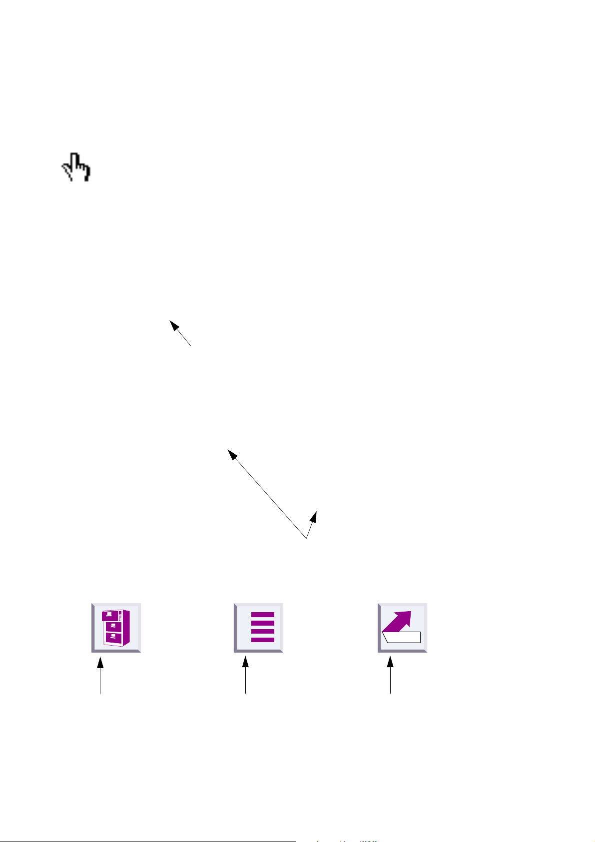
The following controls are available in Acrobat Reader or in the context menu (right mouse
button):
Click here when you see this hand.
Contents
Introduction . . . . . . . . . . . . . . . . . . . . . . . . . . . . . . . . . . . . . . . . . . . . . . . . . . . . . . . . . .9
What is a Gigaset M101 Data? . . . . . . . . . . . . . . . . . . . . . . . . . . . . . . . . . . . . . . . . . . . .9
Meaning of "local adapter" and "remote adapter" . . . . . . . . . . . . . . . . . . . . . . . . . . . . .10
Meaning of "base" and "portable part" . . . . . . . . . . . . . . . . . . . . . . . . . . . . . . . . . . . . . .10
Click here to jump to this section.
11.
It may be useful to switch the operating mode from "A T commands
(PC)" to one of the two other operating modes. This setting concerns the protocol on the serial interface, especially the speed adjustment.
12.
Close the program with "OK".
In the event of errors or for further information, see
program options" on page 18
"Setting the operating mode" on page 20
"Configuration
.
Click here to jump to this section.
A
Back
.
Click here to jump
to the table of
contents.
Click here to jump to
the index.
Jump back to the last
position shown.
2
Page 5
û
The most important menus
Starting the program
Registering a Gigaset M101 Data
A
Back
3
Page 6
û
Setting the operating mode
A
Back
4
Page 7
û
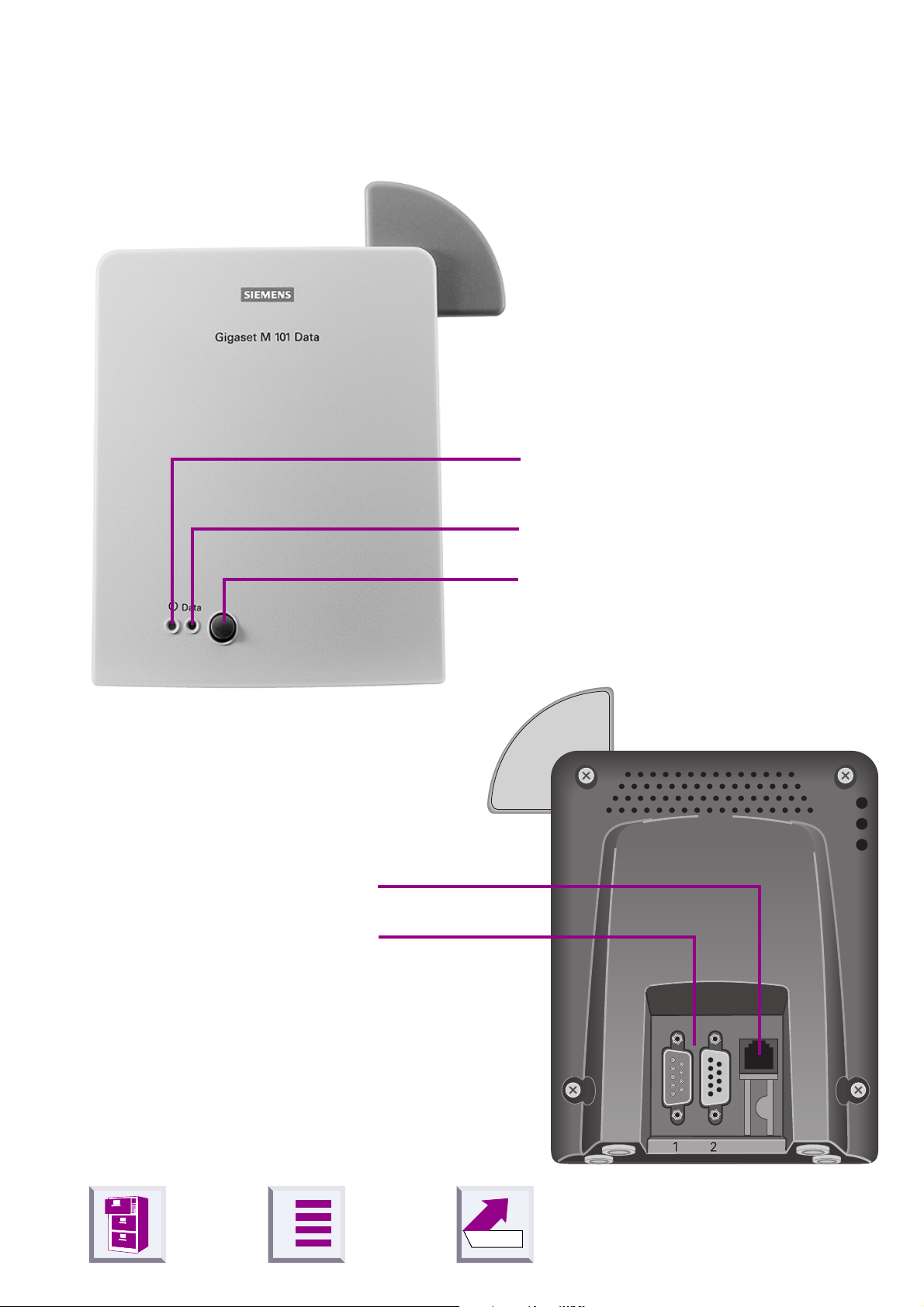
Overview
Front
Operating LED,
1.
illuminated when power supply is
active,
see "LEDs and buttons" on page 28
Back
Mains power supply socket for
1.
plug-type AC adapter
Port for the V.24/RS232
2.
cable
1 = male
2 = female
Data LED, illuminated during
2.
data transfer operations
Registration and reset key
3.
A
Back
5
Page 8

û
Contents
Contents
How to use this manual . . . . . . . . . . . . . . . . . . . . . . . . . . . . . . . . . . . . . . . . . . . . . . . . . . . . . . . . 2
The most important menus . . . . . . . . . . . . . . . . . . . . . . . . . . . . . . . . . . . . . . . . . . . . . . . . . . . . . 3
Overview . . . . . . . . . . . . . . . . . . . . . . . . . . . . . . . . . . . . . . . . . . . . . . . . . . . . . . . . . . . . . . . . . . . 5
Introduction . . . . . . . . . . . . . . . . . . . . . . . . . . . . . . . . . . . . . . . . . . . . . . . . . . . . . . . . . . . . . . . . 8
What is a Gigaset M101 Data? . . . . . . . . . . . . . . . . . . . . . . . . . . . . . . . . . . . . . . . . . . . . . . . . . . 8
Meaning of "local adapter" and "remote adapter" . . . . . . . . . . . . . . . . . . . . . . . . . . . . . . . . . . . . 9
Meaning of "base" and "portable part" . . . . . . . . . . . . . . . . . . . . . . . . . . . . . . . . . . . . . . . . . . . . . 9
Meaning of "(PC)", "(device)" . . . . . . . . . . . . . . . . . . . . . . . . . . . . . . . . . . . . . . . . . . . . . . . . . . . 9
Notes on PC modem operation . . . . . . . . . . . . . . . . . . . . . . . . . . . . . . . . . . . . . . . . . . . . . . . . . 10
Notes on Gigaset Repeater . . . . . . . . . . . . . . . . . . . . . . . . . . . . . . . . . . . . . . . . . . . . . . . . . . . . 10
Putting into service . . . . . . . . . . . . . . . . . . . . . . . . . . . . . . . . . . . . . . . . . . . . . . . . . . . . . . . . . 11
Checking the contents of the package . . . . . . . . . . . . . . . . . . . . . . . . . . . . . . . . . . . . . . . . . . . 11
Installing the program package . . . . . . . . . . . . . . . . . . . . . . . . . . . . . . . . . . . . . . . . . . . . . . . . . 13
Prerequisites for installation . . . . . . . . . . . . . . . . . . . . . . . . . . . . . . . . . . . . . . . . . . . . . . . . . . . 13
Installing . . . . . . . . . . . . . . . . . . . . . . . . . . . . . . . . . . . . . . . . . . . . . . . . . . . . . . . . . . . . . . . . . . 13
Checking the success of installation . . . . . . . . . . . . . . . . . . . . . . . . . . . . . . . . . . . . . . . . . . . . . 13
Connecting adapters . . . . . . . . . . . . . . . . . . . . . . . . . . . . . . . . . . . . . . . . . . . . . . . . . . . . . . . . . 14
Initial configuration . . . . . . . . . . . . . . . . . . . . . . . . . . . . . . . . . . . . . . . . . . . . . . . . . . . . . . . . . 15
Registering Gigaset M101 Data at Gigaset 3070isdn/3075isdn . . . . . . . . . . . . . . . . . . . . . . . . 15
Registering Gigaset M101 Data at Gigaset M101 Data . . . . . . . . . . . . . . . . . . . . . . . . . . . . . . 16
Registering Gigaset M105 Data at Gigaset M101 Data . . . . . . . . . . . . . . . . . . . . . . . . . . . . . . 17
Configuration program options . . . . . . . . . . . . . . . . . . . . . . . . . . . . . . . . . . . . . . . . . . . . . . . 18
General . . . . . . . . . . . . . . . . . . . . . . . . . . . . . . . . . . . . . . . . . . . . . . . . . . . . . . . . . . . . . . . . . . . 18
Starting the configuration program . . . . . . . . . . . . . . . . . . . . . . . . . . . . . . . . . . . . . . . . . . . . . . 18
"Connection" tab . . . . . . . . . . . . . . . . . . . . . . . . . . . . . . . . . . . . . . . . . . . . . . . . . . . . . . . . . . . . 19
Upper section: connecting to the PC . . . . . . . . . . . . . . . . . . . . . . . . . . . . . . . . . . . . . . . . . . . . . 19
Lower section: DECT connection . . . . . . . . . . . . . . . . . . . . . . . . . . . . . . . . . . . . . . . . . . . . . . . 19
"Operating mode" tab . . . . . . . . . . . . . . . . . . . . . . . . . . . . . . . . . . . . . . . . . . . . . . . . . . . . . . . . 20
Setting the operating mode . . . . . . . . . . . . . . . . . . . . . . . . . . . . . . . . . . . . . . . . . . . . . . . . . . . . 20
Special settings for "Direct connection" mode . . . . . . . . . . . . . . . . . . . . . . . . . . . . . . . . . . . . . . 21
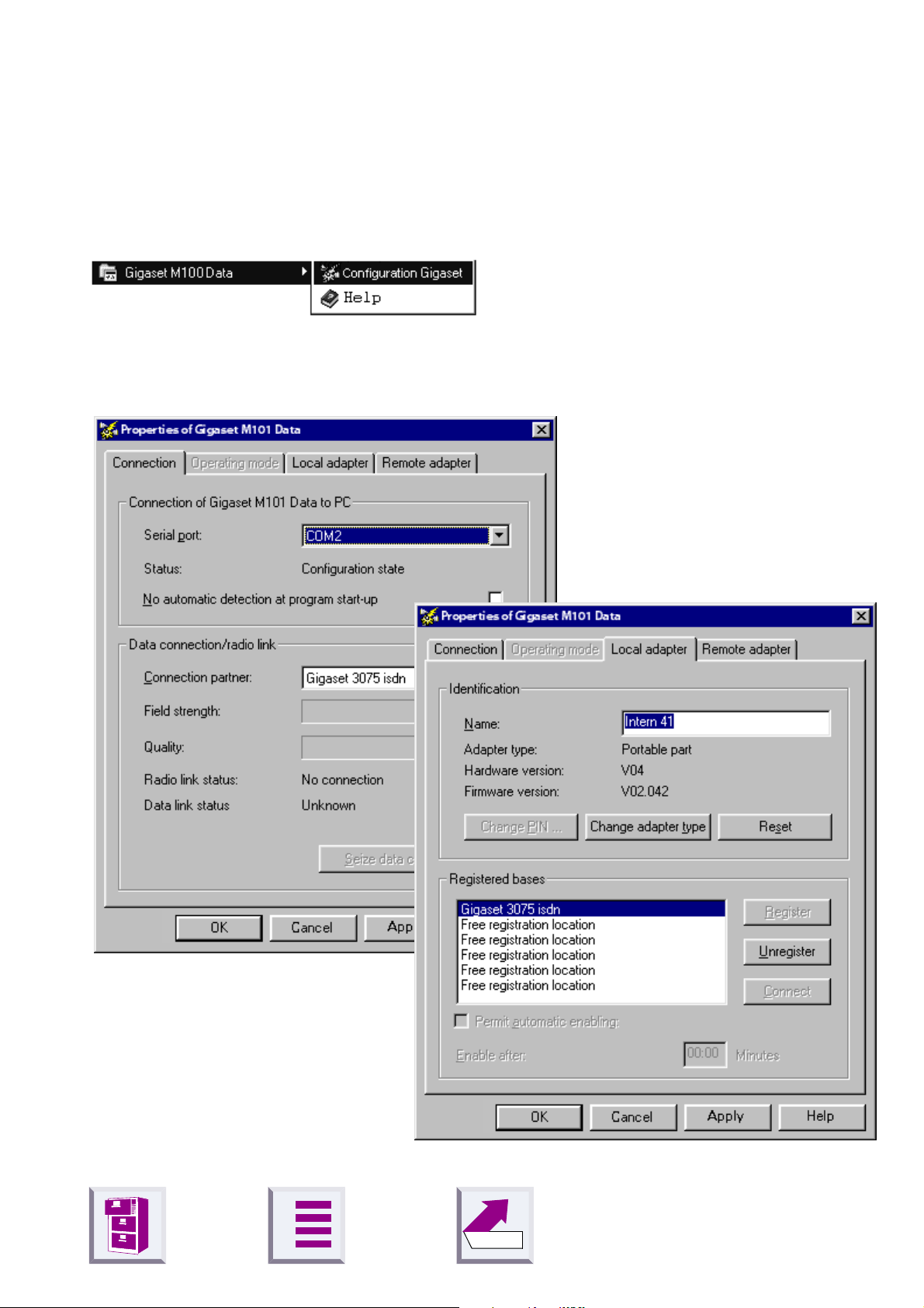
"Local adapter" tab . . . . . . . . . . . . . . . . . . . . . . . . . . . . . . . . . . . . . . . . . . . . . . . . . . . . . . . . . . 23
Changing the name . . . . . . . . . . . . . . . . . . . . . . . . . . . . . . . . . . . . . . . . . . . . . . . . . . . . . . . . . . 23
Changing the adapter type . . . . . . . . . . . . . . . . . . . . . . . . . . . . . . . . . . . . . . . . . . . . . . . . . . . . 23
Registering a portable part . . . . . . . . . . . . . . . . . . . . . . . . . . . . . . . . . . . . . . . . . . . . . . . . . . . . 24
De-registering a portable part . . . . . . . . . . . . . . . . . . . . . . . . . . . . . . . . . . . . . . . . . . . . . . . . . . 25
Automatic enabling . . . . . . . . . . . . . . . . . . . . . . . . . . . . . . . . . . . . . . . . . . . . . . . . . . . . . . . . . . 25
"Remote adapter" tab . . . . . . . . . . . . . . . . . . . . . . . . . . . . . . . . . . . . . . . . . . . . . . . . . . . . . . . . 26
Changing the name . . . . . . . . . . . . . . . . . . . . . . . . . . . . . . . . . . . . . . . . . . . . . . . . . . . . . . . . . . 26
Changing the PIN . . . . . . . . . . . . . . . . . . . . . . . . . . . . . . . . . . . . . . . . . . . . . . . . . . . . . . . . . . . 27
A
Back
6
Page 9

û
Contents
LEDs and buttons . . . . . . . . . . . . . . . . . . . . . . . . . . . . . . . . . . . . . . . . . . . . . . . . . . . . . . . . . . 28
Button functions . . . . . . . . . . . . . . . . . . . . . . . . . . . . . . . . . . . . . . . . . . . . . . . . . . . . . . . . . . . . . 28
Setting a base to registration mode . . . . . . . . . . . . . . . . . . . . . . . . . . . . . . . . . . . . . . . . . . . . . . 28
Resetting the device to the factory defaults . . . . . . . . . . . . . . . . . . . . . . . . . . . . . . . . . . . . . . . 28
LED 1: Gigaset M101 Data status . . . . . . . . . . . . . . . . . . . . . . . . . . . . . . . . . . . . . . . . . . . . . . . 28
LED 2: data transfer . . . . . . . . . . . . . . . . . . . . . . . . . . . . . . . . . . . . . . . . . . . . . . . . . . . . . . . . . 29
Notes on installation and operation . . . . . . . . . . . . . . . . . . . . . . . . . . . . . . . . . . . . . . . . . . . . . . 30
Place of installation . . . . . . . . . . . . . . . . . . . . . . . . . . . . . . . . . . . . . . . . . . . . . . . . . . . . . . . . . . 30
Temperature and ambient conditions . . . . . . . . . . . . . . . . . . . . . . . . . . . . . . . . . . . . . . . . . . . . 30
Why set an operating mode? Technical background . . . . . . . . . . . . . . . . . . . . . . . . . . . . . . . . 30
Tips&tricks, settings . . . . . . . . . . . . . . . . . . . . . . . . . . . . . . . . . . . . . . . . . . . . . . . . . . . . . . . . 32
Access to different V.24 terminals from a laptop: . . . . . . . . . . . . . . . . . . . . . . . . . . . . . . . . . . . 32
Sequential access from multiple computers to a terminal (modem-sharing): . . . . . . . . . . . . . . 33
PC-PC direct cable connection: via RS232/V.24 interface . . . . . . . . . . . . . . . . . . . . . . . . . . . . 34
Setting the direct connection to the correct baud rate . . . . . . . . . . . . . . . . . . . . . . . . . . . . . . . . 34
Sharing files . . . . . . . . . . . . . . . . . . . . . . . . . . . . . . . . . . . . . . . . . . . . . . . . . . . . . . . . . . . . . . . . 40
Examples of PC-PC direct cable connection problems . . . . . . . . . . . . . . . . . . . . . . . . . . . . . . . 42
Mac and other operating systems . . . . . . . . . . . . . . . . . . . . . . . . . . . . . . . . . . . . . . . . . . . . . . . 42
What happens if... . . . . . . . . . . . . . . . . . . . . . . . . . . . . . . . . . . . . . . . . . . . . . . . . . . . . . . . . . . 43
Support . . . . . . . . . . . . . . . . . . . . . . . . . . . . . . . . . . . . . . . . . . . . . . . . . . . . . . . . . . . . . . . . . . . 44
Updates and news on the Internet . . . . . . . . . . . . . . . . . . . . . . . . . . . . . . . . . . . . . . . . . . . . . . . 44
Notes on sending faxes directly from the PC . . . . . . . . . . . . . . . . . . . . . . . . . . . . . . . . . . . . . . 44
Technical data . . . . . . . . . . . . . . . . . . . . . . . . . . . . . . . . . . . . . . . . . . . . . . . . . . . . . . . . . . . . . . 49
The V.24 interface . . . . . . . . . . . . . . . . . . . . . . . . . . . . . . . . . . . . . . . . . . . . . . . . . . . . . . . . . . . 49
Safety precautions . . . . . . . . . . . . . . . . . . . . . . . . . . . . . . . . . . . . . . . . . . . . . . . . . . . . . . . . . . . 51
Index . . . . . . . . . . . . . . . . . . . . . . . . . . . . . . . . . . . . . . . . . . . . . . . . . . . . . . . . . . . . . . . . . . . . . 52
A
Back
7
Page 10
û
Introduction
What is a Gigaset M101 Data?
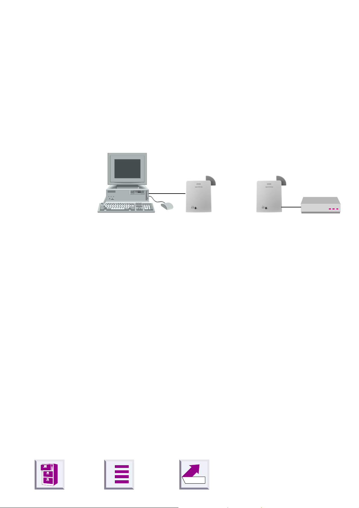
Your Gigaset M101 Data is a cordless V.24/RS232 serial interface consisting of two adapters: the
The adapter connected to the PC is known as the "local adapter".
The "remote adapter" is connected to a peripheral device, e.g. a modem.
local adapter
Radio link
and the
Introduction
remote adapter
.
Local adapter Remote adapter
The connection between the PC and the peripheral device is routed via
the radio link between the local adapter and the remote adapter.
In addition to both adapters, the application features a configuration program.
All Gigaset M101 units are "base" type adapters by default. The Gigaset
M101 Data connected to the PC automatically becomes a "portable part"
type adapter when the device is configured for the first time. The portable
part must be registered at the base station.
Of the two adapters,
z
one is a "base"; this is usually the remote adapter,
z
the other is a "portable part"; this is usually the local adapter.
Every Gigaset M101 Data can be operated either as a local adapter or as
a remote adapter.
A
Back
8
Page 11

û
Meaning of "local adapter" and "remote adapter"
These names are used for identifying the adapters and their role in data
communication. The "local adapter" is the adapter that performs all configurations (also for the "remote adapter"). This means that the Gigaset
M101 Data setup routine does not have to be installed on the second PC
in the case of a direct cable connection.
Meaning of "base" and "portable part"
This is an assignment in the DECT connection (FP = Fixed Part, PP=Portable Part) and refers exclusively to the air interface. A base is the same
as a base station in Gigaset telephony . Here, portable part is the same as
handset. This is defined, for example, through the registration option.
Only one Gigaset M101 Data "portable part" can be registered at a Gigaset M101 Data "base".
Introduction
Meaning of "(PC)", "(device)"
In the case of PC, the Gigaset M101 Data unit connected behaves like a
modem/device and "acts" out the function of the PC COM port.
In the case of
like a PC and "acts" out the function of the connected device.
In the case of
(company-specific) protocols of other companies, such as A VM are taken
into account, the speed settings in this case do not correspond to AT
Hayes commands.
device
AVM compatible
, the Gigaset M101 Data unit connected behaves
, the special features of the proprietary
A
Back
9
Page 12
û
Notes on PC modem operation
When using a modem, software malfunctions in the PC (e.g. an
operating system crash or program errors in the application software) can prevent the cleardown of a modem connection from
a telephone line.
that you seize!
serial cable, malfunctions of this kind can also occur here. If
such a problem occurs, check the status of your modem and, if
applicable, reset it. In the case of one-sided interruption of the
mains supply or complete interruption of your Gigaset M101 Data’s hop, the interface’s status lines are reset to the initial status
in the remote adapter within two minutes (a modem then clears
down the connection).
Introduction
You incur connection costs for trunk lines
Since your Gigaset M101 Data only replaces a
Whenever possible, operate the adapter registered as
part
at your PC (local adapter), since any malfunctions on the
portable part side can be displayed, for technical reasons, more
quickly here than at the base,
page 28
.
Notes on Gigaset Repeater
The Gigaset Repeater
range.
The repeater was designed for use in connection with
Gigaset 2000/3000 base stations.
cannot
portable
see "LEDs and buttons" on
be used to extend the radio
A
Back
10
Page 13
û
Putting into service
Follow the step-by-step instructions described below for putting the
equipment into service:
1.
Check the contents of the package,
2.
Deactivate the PC,
3.
Connect Gigaset M101 Data to a free COM port
4.
Activate the PC
5.
Install the configuration program,
Putting into service
6.
Conclude commissioning by performing an initial configuration,
tial configuration" on page 15
Checking the contents of the package
The package contains: M101Data
Gigaset M101 Data 1
Plug-type AC adapter C39280-Z4-C59/C39280-Z4-C168
for mains connection
Serial 9-pin connection cable for connecting
the V.24/RS232 interface
CD-ROM with the installation program and operating in-
structions
see "Ini-
1
1
1
A
Back
11
Page 14
û
Putting into service
Important information
Before you put the Gigaset M101 Data into service, the peripheral device that you want to operate as a cordless unit
(modem, PABX) must be configured at the COM port on the PC
side since it is to be used for transferring data. For information
on configuration, see the appropriate documentation on the peripheral device and your computer’s operating system. This
configuration is necessary in particular for plug&play installations, as otherwise errors can occur depending on the installation routine of the connected peripheral unit.
If you want to operate a modem, for example, via the radio link,
first connect the modem directly to the PC, configure it, set up a
test connection, and then install the radio link. To do this, disconnect the modem from the PC, connect the Gigaset M101
Data and perform the configuration.
When choosing a location for the devices, see
stallation and operation" on page 30
.
"Notes on in-
A
Back
12
Page 15
û
Installing the program package
Prerequisites for installation
For installation, you need:
z
an IBM-compatible PC with the following configuration:
– Win 95, Win 98, Win 2000, Win ME or Win NT 4.0 operating system
– 5 MB free hard disk memory
– 1 free V.24/RS232 serial interface as COM port
z
the CD-ROM containing the installation program
Installing
z
Start the PC and close down any programs active after start-up.
z
Insert the data carrier supplied in the drive (autostart).
Putting into service
z
If the CD does not start automatically, select
Control Panel
grams
z
Select
message
message with OK.
If a Gigaset M101 Data unit is already connected, this is detected and
the configuration program starts.
z
Terminate the configuration program with OK, this concludes the installation routine.
Checking the success of installation
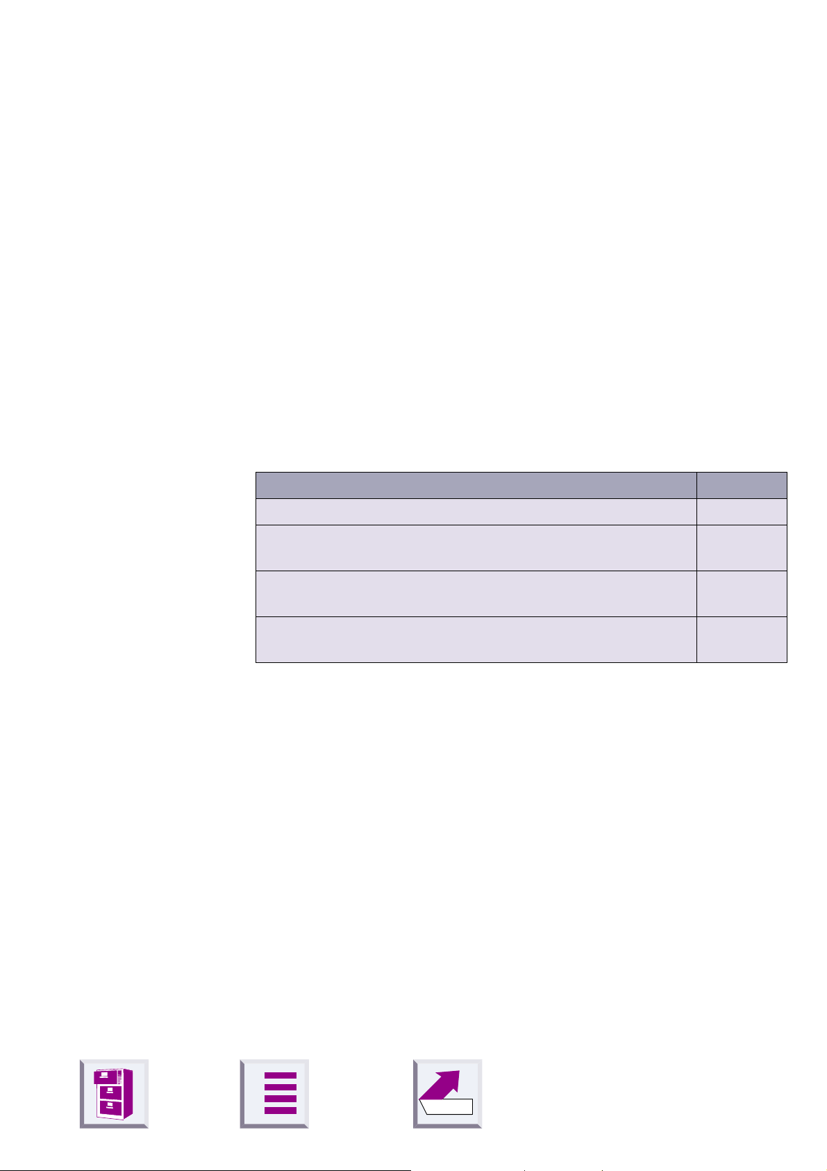
The following errors can occur during installation:
Problem Result
Insufficient memory Error message, try freeing some disk
No COM port free at the PC Error message, setup can be com-
icon. Note: Not necessary for Win ME.
Install
"No Gigaset M101 Data connected"
Settings
in the
. The installation program starts. During installation, the
Start
menu. Double-click the
space on your hard drive.
pleted.
appears. Confirm this
followed by
Add/Remove Pro-
PC crashes during
installation
If no errors occur, all files are installed in the selected language version
and your PC contains a "Gigaset M100 Data" program group. This contains the "Set Gigaset" configuration program, a help function and these
operating instructions.
A
Back
Automatic correction during next attempt.
13
Page 16

û
Connecting adapters
z
To avoid damaging your Gigaset M101 Data and the PC, the V.24/
RS232 cable should only be connected when the power supply is
switched off.
z
Connect a Gigaset M101 Data to the V.24/RS232 interface of the PC
(COM port). Some V.24 plugs have a plastic protrusion and cannot be
properly arrested. If this is the case, use the cable supplied as an extension.
z
Connect both adapters to the plug-type AC adapters (C39280-Z4-C59/
C39280-Z4-C168) and insert these PSUs in 230 V AC and 50 Hz sockets.
Putting into service
Y ou can now perform initial configuration,
page 15
.
see "Initial configuration" on
A
Back
14
Page 17

Initial configuration
û
Initial configuration
The purpose of initial configuration is to register the portable part at the
base station. You can only perform initial configuration with the configuration program. The Gigaset M101 Data can be operated at other PCs/
operating systems once you have completed initial configuration.
Registering Gigaset M101 Data at Gigaset 3070isdn/ 3075isdn
Proceed as follows:
1.
Install Gigaset M101 Data
2.
Switch Gigaset 3070isdn/3075isdn to registration mode (press LED).
3.
Start the Gigaset M101 Data configuration program.
4.
Select the
5.
Click the
The local adapter is now switched to
mally , you must enter the base station PIN before registration is possible.
However , you can skip this step during initial configuration since the base
station has the factory-set PIN ("0000"). This is automatically set by the
program during initial configuration.
6.
Click OK. The registration procedure starts and the message "
quired base is ready for registration, the local adapter logs on.
Check that the base is ready for registration.
The two devices are automatically synchronised. An entry now appears
in the
7.
Close the program with OK.
In the event of errors or for further information, see
gram options" on page 18
Local adapter
Register
Registered adapter
button.
tab.
list.
.
Portable part
" appears on the screen.
operating mode. Nor-
If the re-
"Configuration pro-
A
Back
15
Page 18

Initial configuration
û
Registering Gigaset M101 Data at Gigaset M101 Data
Proceed as follows:
1.
Disconnect both adapters and the PC from the power supply.
2.
Connect one Gigaset M101 Data to the PC.
3.
Connect the PC and both Gigaset M101 Data units to the power supply.
4.
Start the
5.
Press and hold down the black button on the Gigaset M101 Data (base
station)
dicate that the system is ready for registration by flashing in sequence.
6.
Select the
7.
Click the
The local adapter is now switched to
mally , you must enter the base station PIN before registration is possible.
However , you can skip this step during initial configuration since the base
station has the factory-set PIN ("0000"). This is automatically set by the
program during initial configuration.
8.
Click OK. The registration procedure starts and the message "
quired base is ready for registration, the local adapter logs on.
Check that the base is ready for registration.
The two devices are automatically synchronised. An entry now appears
in the
9.
Assign a suitable name to the local adapter, e.g. "PC".
10.
Open the
The registered portable part now also appears in this window.
Set Gigaset
not
connected to the PC. After approx. 10 seconds, the LEDs in-
Local adapter
Register
Registered bases
Remote adapter
program at the PC.
tab.
button.
list.
tab and assign a name to it, e.g. "Modem".
Portable part
" appears on the screen.
operating mode. Nor-
If the re-
11.
It may be useful to switch the operating mode from "A T commands (PC)"
to one of the two other operating modes. This setting concerns the protocol on the serial interface, especially the speed adjustment. For more information, see
12.
Close the program with OK.
In the event of errors or for further information, see
gram options" on page 18
A
"Setting the operating mode" on page 20
"Configuration pro-
.
Back
.
16
Page 19

Initial configuration
û
Registering Gigaset M105 Data at Gigaset M101 Data
Proceed as follows:
1.
Gigaset M105 Data has been installed.
2.
If the M101 is not already in the standard factory setting, make sure that
the M101 is set to the type "Base". Take the type display and the switchover options from the configuration program.
3.
Press and hold down the black button on the Gigaset M101 Data (partner
station). After about 10 seconds, the LEDs flash alternately to indicate
"ready for registration".
4.
Start the
is connected.
5.
Select the
6.
Click the
7.
Click OK. The registration procedure starts and the message "
quired base is ready for registration, the local adapter logs on.
Check that the base is ready for registration.
The two devices set themselves up automatically. There should now be
one entry in the
8.
Give the local station a suitable name, e.g. "PC".
9.
Select the
say, "Gigaset M101 Data". In this case too, the registered subscriber is
indicated in the window.
10.
Select the
you want. For a direct connection (PC-PC connection) set, say, the following parameters: Bits per second: 115200 - Data bits: 8 - Parity: None
(N) - Stop bits: 1 - Protocol: Hardware (RTS/CTS).
11.
Quit the program with OK.
Set Gigaset
Local station
Register
Remote adapter
Operating mode
program on the PC to which the Gigaset M105 Data
button and enter the PIN.
Registered bases
registration card. The type is
" appears on the screen.
list.
registration card and call the partner station,
registration card and set the operating mode
Portable part
.
If the re-
A
Back
17
Page 20

Configuration program options
û
Configuration program options
General
Y ou will rarely need the majority of configuration options for the simple implementation of two Gigaset M101 Data units for cordless modem operation. A range of settings is available for future developments.
Starting the configuration program
Under
nally
The configuration program offers a dialog box entitled
gaset M101 Data
mode, Local adapter
Start
, select
Set Gigaset
Programs
.
which contains the four tabs
and
followed by
Remote adapter
Gigaset M100 Data
.
Connection, Operating
and fi-
Properties of Gi-
A number of special fields are also provided for special inputs.
A
Back
18
Page 21

û
"Connection" tab
Upper section: connecting to the PC
You can set the PC COM port at which the local adapter is connected in
the upper section of the tab.
Configuration program options
We recommend leaving the option
start-up
COM ports and determines where the adapter is connected. Manual interface selection is only recommended if there is more than one Gigaset
M101 Data unit connected to the PC.
As soon as the program finds an adapter or identifies the manually selected interface, it sends it the configuration command via the control
lines. This action switches the adapter to configuration status. This is indicated by the
only be configured under these conditions. Your Gigaset M101 Data will
automatically switch the adapter back to operating status at the end of the
program.
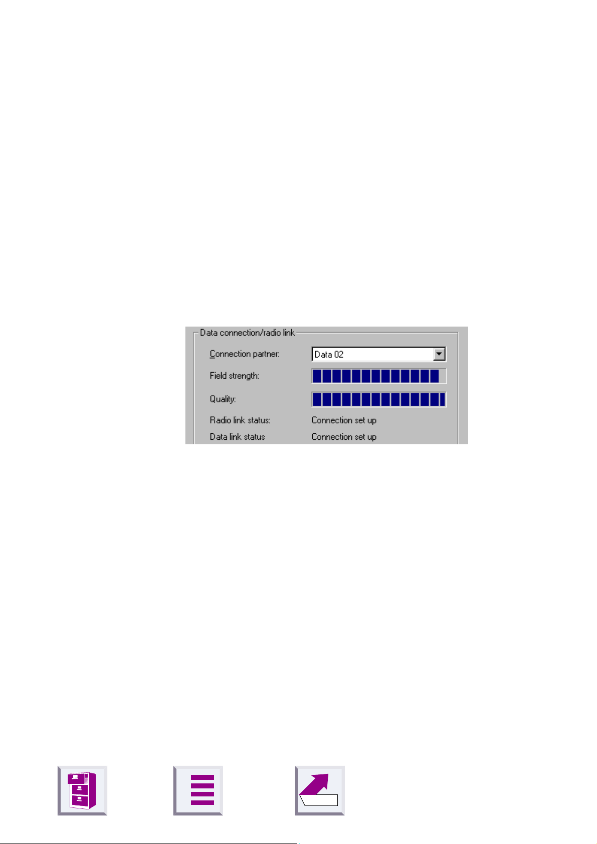
Lower section: DECT connection
This section indicates whether a radio connection exists and if so, to
which remote adapter. It also indicates the quality of the connection.
A remote adapter must be registered before it can be selected here.
A
deactivated (as shown). The program then checks the existing
Status
No automatic detection at program
display in the dialog box. Gigaset M101 Data can
19
Back
Page 22

û
"Operating mode" tab
Important:
If one of the adapters is set to "A T commands (PC)" or "AVM compatible
(PC)", the other adapter must switch to the corresponding operating
mode "AT commands (device)" or "AVM compatible (device)". If one
adapter is switched to "Direct connection", the other adapter must also
be switched to this mode. The appropriate switches are performed automatically if you select an operating mode for a Gigaset M101 Data unit.
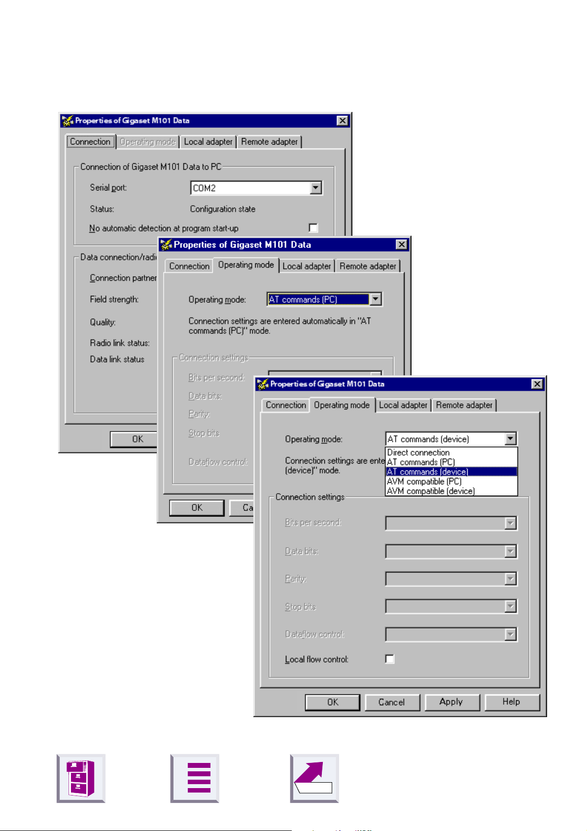
Setting the operating mode
Configuration program options
Open the
The three connection types are used for different purposes:
Direct connection
AT commands
(PC)#
Î
page 9
AT commands
(device)#
Î
page 9
Operating mode
The permanent transmission parameters for the
PC’s COM port are manually set at the computer
without automatic baud rate or data format recognition. This is always useful if the device at the remote
adapter does not support baud rate or data format
recognition as performed by conventional modems,
e.g. in the case of a second PC.
Automatic recognition of the transmission parameters based on the data from the PC at the local
adapter.
Automatic emulation of the transmission parameters based on the values received from the PC at
the remote adapter.
tab and select one of the five modes:
AVM compatible
(PC)#
Î
page 9
AVM compatible
(device)
A
Automatic recognition of the transmission parameters in AVM-compatible format based on the data
from the PC at the local adapter.
Automatic emulation of the transmission parameters in AVM-compatible format on the basis values
received from the PC at the remote adapter.
20
Back
Page 23

û
Special settings for "Direct connection" mode
Direct connection
In
box are activated: you can set the transmission parameters for the COM
port at the PC.
Use the default settings if you do not want to change any other parameters. In the event of malfunctions, reduce the speed in the
ond
field. Set your communication software likewise to this value.
In the case of changes, only permitted values are accepted in the individual fields, even for manual inputs.
mode, the fields in the lower section of the dialog
Configuration program options
Bits per sec-
Dataflow control list
You can set whether the data transmission is controlled by the hardware
or software. The usual setting is
quest To Send" and CTS means "Clear To Send".
A
Back
Hardware (RTS/CTS)
. RTS means "Re-
21
Page 24

û
Configuration program options
Local flow control check box
Local flow control normally does not have to be activated except when operating low-memory V.24 terminals. Activating local flow control can help
in the event of data transmission problems (e.g. sending faxes, operating
a serial printer).
When local flow control is active, the Gigaset M101 Data unit connected
to the V.24 terminal immediately stops outputting data in the direction of
the terminal when a STOP signal is received and saves this data in its
own memory . This ensures that the PC only sends data that can be processed by the transmission route (saved). If local flow control is not activated, the V.24 terminal’s STOP signal is transferred to the PC. During
this time (less than 10 ms), the PC continues to send data. All of this data
is output by the Gigaset M101 Data unit in the direction of the V.24 terminal. If the terminal does not have sufficient memory to receive this data,
the data is lost.
A
Back
22
Page 25

û
"Local adapter" tab
Changing the name
The purpose of adapter names is to provide a rapid overview. The local
adapter must be called "PC". The remote adapters should, if possible, be
named after the peripheral device connected, e.g. "Modem".
Adapter names can be changed by entering or changing a name in the
Name field. Names can contain letters and digits as well as blanks. The
name must not contain more than 20 characters.
Changing the adapter type
Normally , a portable part is operated at the PC and the base station is operated at the peripheral device. Other constellations, however, are possible in which both adapters are connected to a PC in order, for example,
to create a cordless data connection between two PCs. In this case, the
adapter type of one of Gigaset M101 Data units must be
adapter type of the other must be
more than one remote adapter in order to control a second PC or the modem alternately. It may also be necessary here to change the adapter
type at one of the Gigaset M101 Data units.
Configuration program options
base
portable part
. Or you can implement
while the
z
Ensure that the correct Gigaset M101 Data is connected at the PC.
z
Select
ground. You can see that it has been performed when the information
in the
Change adapter type
Adapter type
line changes.
. The change is performed in the back-
A
Back
23
Page 26

û
Registering a portable part
Both adapters are powered. One Gigaset M101 Data unit is connected to
the PC.
Configuration program options
Select the
The following dialog box appears:
Local adapter
tab.
Up to six registered devices can be entered in the
window . Depending on the adapter type of the local adapter ,
adapter
Select a portable part and click
A
Registered bases
or
Back
is displayed.
Register
.
Registered adapter
Registered
24
Page 27

û
Configuration program options
The following window appears when the local adapter is a base (factory
setting):
OK
Click
The portable part now searches for the base station and automatically
registers at it.
If registration is not possible (base station not in registration mode or not
powered, incorrect PIN), the system will indicate the necessary steps for
resolving this problem.
De-registering a portable part
Select the adapter in the window and click
Automatic enabling
The automatic enabling feature eliminates the need to enable the data
connection manually. If the V.24 interface is not used for a set length of
time (no activity on the V.24 interface and control line DTR = 0), then this
is automatically enabled and can be automatically seized by another portable part.
At least one portable part must be registered before the automatic enabling feature can be set. In the window Properties of Gigaset M101 Data,
under the tab
"Registering a portable part" on page 24).
Enter the desired number of minutes in the field "Enable after:"
.
Local adapter
Unregister
click on „Permit automatic enabling: (see
.
A
Back
25
Page 28
û
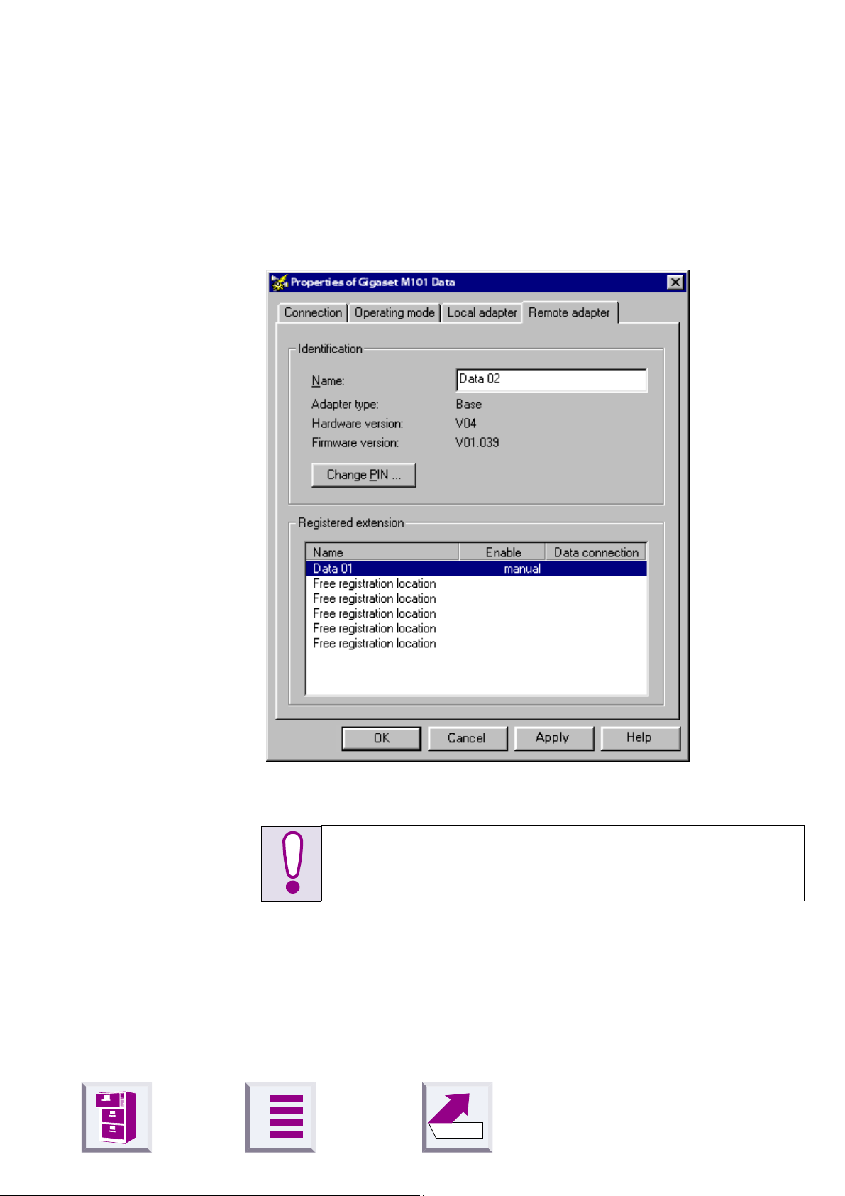
"Remote adapter" tab
This tab is used for configuring the remote adapter that is not connected
to the PC. Registration must be performed first so that the two Gigaset
M101 Data units can communicate.
Configuration program options
Changing the name
Remote adapter
The
Local adapter
the
As for local adapter,
A
tab is only available after registration on
tab.
see "Changing the name" on page 23
Back
.
26
Page 29

û
Changing the PIN
Configuration program options
Change PIN
Click
Enter the old PIN (PIN: 1–8 digits, default: 0000) to obtain authorisation
to change the PIN and press the tab key.
Enter the new PIN and press the tab key.
Enter the new PIN in the Repeat new PIN field and click OK.
.
The PIN is changed if the new PINs entered are identical and if the correct
old PIN is entered. Otherwise, a warning appears.
A
Back
27
Page 30

û
LED 1 flashes slowly The adapter is searching for the partner or
has not been registered.
LED 1 flashes quickly The partner was found, the data connection
is not assigned to the transmission route.
LED 1 is constantly lit The partner was found, the transmission
route is on stand-by.
LEDs and buttons
There are two LEDs and a black button on the front of the Gigaset M101
Data unit.
Button functions
Setting a base to registration mode
Press the button on a powered base-type device for 10 seconds. The two
LEDs flash in sequence, thus indicating that the device is in registration
mode. Registration mode is automatically deactivated after successful
registration or after 10 minutes: the flashing stops.
Resetting the device to the factory defaults
LEDs and buttons
For Gigaset 101 Data only:
Press and hold down the black button on the front of the device while the
unit is being disconnected from the power supply. Reconnect the power
supply keeping the button depressed. LED 2 lights up after 10 seconds.
This LED goes out in another 10 seconds indicating that the reset operation was successful. Release the button. The local adapter can be reset
via the configuration mask.
LED 1: Gigaset M101 Data status
LED 1 indicates stand-by mode:
A
Back
28
Page 31

û
LED 2 off No data transfer
LED 2 flickers/is lit Data transfer active
LED 2: data transfer
LED 2 indicates the status of the transmission route on the V.24/RS232
interface:
LEDs and buttons
A
29
Back
Page 32

û
Notes on installation and operation
Place of installation
There must be a 220/230 V AC and 50 Hz power socket nearby.
The Gigaset M101 Data should not be installed in the immediate vicinity
of other electronic devices, such as hi-fi systems, office equipment or microwave ovens, otherwise there is a risk of mutual interference.
Place the Gigaset M101 Data unit on a level, non-slip surface. The device
feet do not leave any unsightly marks. However, in view of the many different varnishes and polishes currently used for furniture, the possibility
of marks being left cannot be ruled out.
Radio communication between base and portable part is based on the
DECT standard. The Gigaset M101 Data complies fully with the relevant
European directives. Should you nevertheless experience sound or picture distortion with your satellite signal receiving equipment, please get in
touch with your dealer to have it tested for shielding faults.
LEDs and buttons
Depending on the ambient conditions, the maximum range for a radio
connection between the local adapter and the remote adapter is approx.
300 m outdoors and approx. 50 m indoors.
Temperature and ambient conditions
Gigaset M101 Data is designed for operation in protected rooms with a
temperature range from +5°C to +45°C and 20% to 75% relative humidity .
Do not install the Gigaset M101 Data unit in damp environments, such as
a bathroom or laundry room. Do not expose it to direct sunlight or other
heat sources, such as radiators.
Why set an operating mode? Technical background
Configuration must always be performed for both M101 units on a V.24
link.
Serial interfaces are more than connectors. They have an integrated dataflow control, control lines, data lines and an adjustable speed function.
Serial interface are used to transport data in various formats.
Modems are usually controlled with AT commands or proprietary protocols that they receive via their serial interface. On the basis of these commands, modems can recognise the data format and speed at which the
data is transferred. The automatic recognition of transmission parameters
A
Back
30
Page 33

û
LEDs and buttons
is important and must be emulated by the radio link if a device that understands the A T or AV M-compatible commands and that is used for parameter synchronisation is connected to the remote adapter.
A cordless extension cable between a PC and, for example, a modem
must detect the transmission parameters to be used at the PC interface
for communication between this interface and the modem. On the modem
side, the functions generated by the PC must also be created for the serial interface.
On the radio link, data is transmitted according to a radio protocol that has
nothing to do with the serial interface.
If a device which cannot detect transmission parameters in the same way
as a modem is connected to the remote adapter, "Direct connection" is
selected as the operating mode.
There are
1. Direct connection:
that are not controlled with AT or AVM-compatible commands.
2. A T commands or AVM compatible (PC):
the local adapter. The Gigaset M101 Data unit determines the conditions
on the serial interface in the same way as a modem. In addition to the data, the transmission parameters are also transmitted to the remote adapter which then transfers the data to the connected device.
3. A T commands or A VM compatible (device):
remote adapter controls a terminal that understands AT commands.
five
possible operating modes for every Gigaset M101 Data:
this operating mode is implemented for all devices
this is the operating mode for
in this operating mode, the
A
Back
31
Page 34

û
Tips&tricks, settings
This section describes settings, implementation options and programming methods.
Access to different V.24 terminals from a laptop:
Tips&tricks, settings
z
All terminals (PC, modem, Gigaset 307x) can be accessed from a laptop.
z
Only one data connection at a time can ever be set up to a terminal.
z
You must select the relevant connection partner in the configuration
mask in order to switch between the various terminals. This can be
done in the
19) and via the
z
If Gigaset 307x, for example, is selected as the connection partner,
then an incoming call at the modem, for example, cannot be signalled
at the laptop. This is not resolved by "permit automatic enabling" feature (Îpage 25).
Connection partner
Connect
button in the
list in the
Connection
Local adapter
tab (Îpage
tab (Îpage 23).
A
Back
32
Page 35

Tips&tricks, settings
û
Sequential access from multiple computers to a terminal (modem-sharing):
z
Multiple portable parts (PC, laptop) share a terminal (modem).
z
Only one data connection at a time can ever be set up from a "portable
part to the terminal".
z
Simultaneous access from both portable parts to the modem is not
possible.
z
If the data connection, for example, is seized by the PC, and the laptop
would now like to be able to access the modem, there are two ways in
which the laptop can reach the data connection:
a) the laptop user asks the PC user to manually enable the data connection. This is done by pressing the
button in the configuration mask’s
data connection can only now be seized by another portable part. This
is done at the V.24 interface.
b) the "permit automatic enabling" feature eliminates the need to manually enable the data connection (Îpage 25). Automatic enabling is
configured with the help of the configuration mask in the
tab (Îpage 23). If the V.24 interface is not used for a particular length
of time (no activity at the V .24 interface and control line DTR = 0), then
it is automatically enabled and can thus be seized by another portable
part.
Clear down data connection
Connection
tab (Îpage 19). The
Local adapter
A
Back
33
Page 36

Tips&tricks, settings
û
PC-PC direct cable connection: via RS232/V.24 interface
The problem that often occurs with PC-PC direct cable connection is incorrect baud rate setting. The following section describes the configuration of a PC-PC direct cable connection at a Win95 system (similar for
WIN98).
Before using the actual Gigaset M101 Data unit, application functionality
should be checked using a null-modem cable. After the test, remove the
null-modem cable and install the cable supplied. This accelerates fault
detection and clearance. If this is not possible, the precise configuration
is to be examined.
z
The Gigaset M101 Data unit can be set to a fixed baud rate (direct connection 115200 bps with HW handshake).
Setting the direct connection to the correct baud rate
1.
Open the terminal program
First of all, open a terminal program (e.g. Win95 HyperTerminal via
Hypertrm.exe) at both PCs and ensure that the correct COM port is being
accessed.
Set up a direct connection via COMx (COM 1 was selected in the example).
A
Back
34
Page 37

û
Tips&tricks, settings
Then set the port speed:
The baud rate (max. 1 15200) and HW handshake (default setting) are set
in this mask. If you can now transfer data from one PC to another, proceed with the second step.
2.
Set the direct cable connection parameters
Exit the terminal program at one of the PCs. Under the Win95 Start menu,
select
window . Double-click the
Properties
icon in the folder
Settings
window). Select the
Control Panel
>
System
.
and open the window
icon (you should now see the
Device Manager
tab. Find the
Control Panel
System
Modem
A
Back
35
Page 38

û
Tips&tricks, settings
Double-click the icon to expand the branch. The setting
ble at COMx
your configuration and double-click it to open another subfolder.
should be available. Select the appropriate COM port for
Null-Modem Ca-
A
Back
36
Page 39

û
Modem
This
be set to 115200 bps.
tab contains the setting for the maximum speed. This should
Tips&tricks, settings
Activate
Click OK to exit each window.
3.
Test the baud rate setting
Open the
Start > Programs > Accessories
If this icon is missing, you may have to reinstall the appropriate software
from the Win 95 system CD.
To do this, select
Setup, Communications, Details, Direct Cable Connection
Hardware
direct cable connection
under Use flow control in
Control Panel, Add/Remove Programs, Windows
program under
.
Connection > Advanced
.
.
A
Back
37
Page 40

û
Tips&tricks, settings
Select
Modem Cable at COM 1
Change
and activate
.
Guest
. Then enter the interface, e.g.
Null-
To enable access by the other PC, the host (controlling party) and guest
(accessing party) as well as the file and print sharing option must be activated.
A
Back
38
Page 41

û
Tips&tricks, settings
Click File and Print Sharing in the sub-window.
Set the parameters here. If a change was made, new drivers are loaded
and Windows must be restarted.
If file and print sharing was already activate, the computer does not need
to be restarted. Otherwise, restart your computer.
A
39
Back
Page 42
û
Tips&tricks, settings
If the system was not restarted, the following window appears:
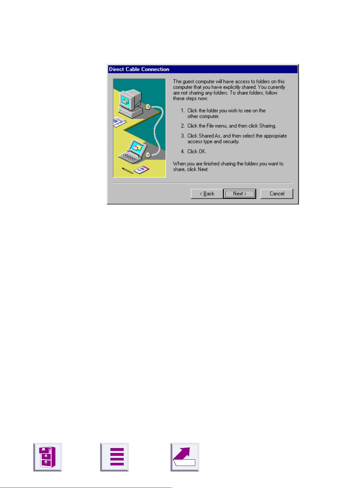
Sharing files
If file/printer sharing has not yet been activated, start to activate it, see
"Sharing files" on page 40
In the final window, select
A window entitled
%1!s
The message
program of the connected computer.
If this is the case, repeat the steps already described at the other computer.
If the Client message does
z
z
z
If this is unsuccessful, the problem may have a different source.
should now appear.
Close the
Open the Task Manager by pressing
see a task called
Repeat steps 2 and 3.
Direct Cable Connection
CLIENT
Direct Cable Connection
Rnaapp
.
Finish
should appear a number of times in the terminal
not
and click OK to answer the questions.
with the status
appear, please try the following:
window.
<CTRL> <ALT> <DEL>
, select it and end it by clicking
End Task
Accessing
. If you
.
Since the Windows information in the previous mask is somewhat confusing, and since no references are made to the File Manager/Explorer, here
is the correct procedure. Once file sharing has been activated and the PC
restarted, you can release files for processing by the other PC via the File
Manager/Explorer .
A
Back
40
Page 43

û
Tips&tricks, settings
Start the
Select the relevant folder and the click
window containing the tabs
Explorer
:
General
and
1
File
Release
>
Properties
appears:
. The following
Assign the other PC user access rights to the files on your hard disk, or
where applicable, activate password protection.
Files that support sharing are identified as follows:
shared
not shared
1. Error in the Windows help, the
A
Back
Properties
submenu is not described.
41
Page 44

û
Examples of PC-PC direct cable connection problems
Other modem drivers installed continue to operate at the same COM port
(special ISDN T A drivers, CAPI modem drivers or similar software are often the cause of the problem).
Once successfully put into service, you can start up the direct cable connection at both computers. Do not forget that one PC must be set as the
host and the other as the guest. Access to files should also be enabled
via the settings Network/File and Print Sharing.
Finally , the subfolders to be accessed by the guest must be released via
the Explorer.
Mac and other operating systems
In general, Gigaset M101 Data can be implemented at every RS232/V .24
interface, provided the data transfer is transparent and not performed on
a company-specific basis (exception: A VM compatible) or with AT Hayes
commands.
Tips&tricks, settings
However, the two Gigaset M101 Data units used must first have been
configured and registered at a Windows 95/98/2K/NT system. Please ensure that the Gigaset M101 Data unit is connected to the correct device
when programming the modem connection. To do this, we recommend
that you place a sticker marked modem or PC, for example, under the Gigaset M101 Data unit so that the correct device is connected later.
A
Back
42
Page 45

û
What happens if...
If a malfunction occurs, check the following points:
z
Both adapters are powered.
z
The cable connections to the connected devices are fully inserted and
screwed in.
z
The adapters are not too far apart and there are no large parts of buildings in between (see
z
Registration was successful.
What happens if...
"Place of installation" on page 30
).
z
The local adapter operating mode is set to
compatible (PC)
Or:
z
The local adapter operating mode is set to
have set the direct connection transmission parameters in your communication software.
If the malfunction still occurs, reset both Gigaset M101 Data units to the
factory defaults, see
page 28
If the malfunction persists after checking all the above points, call the hotline at 0180 5 333 220.
If you are in Austria and your unit
z
is connected to a single connection, contact the Siemens hotline at 01/
1707-5004
z
is connected to a telephone system, contact the relevant installation
company , e.g. Siemens Nebenstellenanlagen in Vienna, NÖ, Bgld. Telephone: 01/1705
.
.
"Resetting the device to the factory defaults" on
A T command (PC) or AVM
Direct connection
and
you
Siemens Service should only be contacted if problems develop with the
device. Your specialist dealer will be happy to answer any questions concerning unit operation. Contact your network operator/provider for questions concerning telephone connection.
Internet: www.siemens.de/gigaset
A
Back
43
Page 46
û
Support
Updates and news on the Internet
www.siemens.com/pc-communication-support
Notes on sending faxes directly from the PC
Y ou may encounter problems if your PC program uses Class 1 fax mode.
Class 1 does not support signal runtime delays which are required for
switching to radio mode.
Class 2 mode, on the other hand is less sensitive. Nevertheless, interference can still occur here due to a bad radio link. If you have problems with
this setting, start the configuration program and check the transmission
quality under
moving the Gigaset M101 Data unit slightly.
Connection
What happens if...
and improve the quality of the connection by
A
Back
44
Page 47

û
Configuration management
Fault Cause Solution
What happens if...
Message from configuration program: "Data adapter not found..."
Configuration on an Apple
Macintosh with "Virtual
PC" is not working.
Message from configuration program: Registration
not possible.
PIN entered is rejected The PIN entered does not
The COM port used is being
used by another program.
The Mac uses an RS422 interface. In RS232 mode, this interface does not receive the DTR
signal that is required by the
configuration program for detecting the Gigaset M101 Data
unit.
The base station may not have
been ready for registration or
the radio connection was temporarily affected by "external
influences".
match the valid PIN.
Close the application that is using
the COM port.
Configure Gigaset M101 Data at an
IBM-compatible PC for this application with the appropriate parameters and then install it downstream
of an Apple Macintosh.
Repeat registration with a base that
is ready. The PIN must be entered
for this (factory setting: "0000").
"Registering a portable part"
See
on page 24
If you forgot the current PIN, reset
the Gigaset M101 Data unit to the
factory defaults. The preset PIN is
"0000". See
to the factory defaults" on page
28
.
.
"Resetting the device
A
Back
45
Page 48

û
Problems with application programs
Fault Cause Solution
What happens if...
PC-PC direct cable connection under WIN95 cannot be configured or is not
working.
Fax function is not working. SW and modem simulate a
Programs that use DCD
(Data Carrierer Detect) are
not working properly.
The modem parameter request function is not working or is not correct.
For example, under Win 95
with <Start><Control Panel><Modems><Diagnostics><More Info>
Baud rate not correctly set.
Class1 fax.
Find out about additional settings in the modem manual or description of your fax software. (The AT command AT+FCLASS=? is useful, provided this is supported by the modem. If the modem’s answer
string contains a 2, then your modem supports Class 2 fax mode).
The DCD output at the local
adapter is controlled by the
DCD input at the remote adapter.
Windows does not follow the
AT Hayes conditions.
Technically specified time delay that are not supported by
the modem’s driver software.
See "PC-PC direct cable connection: via RS232/V.24 interface"
on page 34
Class 1 fax mode is not supported
by Gigaset M101 Data for technical
reasons. Gigaset M101 Data supports Class 2 fax mode.
Use a null-modem cable at the remote adapter.
None
None
.
Data transmission with
Xmodem is very slow.
Laplink 7.0 is not working. Data transmission is switched
Xmodem operates in half-duplex mode. The transmitting
unit waits for acknowledgement after each data package.
The signal delay (20–30 ms per
data block at the DECT interface) significantly reduces the
transmission speed.
during transmission, A T Hayes
commands are not used for
this.
A
Use another transmission protocol,
e.g. Zmodem.
None
46
Back
Page 49

û
Problems with the hardware (PC, modem, ISDN-TA.)
Fault Cause Solution
What happens if...
PABX
system) cannot be configured
via a Gigaset M101 Data.
ELSA TagGo2000 / ISDN
figuration not possible.
The
nal adapter can be used under
AOL
Heliowatt
programmed.
The
adapter cannot be operated
under
tion string specified in the manual.
(telecommunications
ELSA TanGo 2000
.
timers cannot be
ACER ISDN T30
AOL
with the initialisa-
terminal
con-
termi-
The PABX configuration is not
compatible with AT Hayes.
At the system, the baud rate
conversion is switched with an
internal command string that is
not compatible with AT Hayes.
---------------------------- Configure the modem with a di-
No appropriate modem profile
is available.
Incorrect protocol set. Set Gigaset M101 Data to 300
The initialisation string is incorrect.
Configure Gigaset M101 Data
in direct mode (e.g. with
9600,8,N,1).
None.
rectly connected serial cable.
Tests have shown that an oper-
ational X.75 connection is set
up with the modem profile "ISDN ELSA TL V34 X.75 64.000".
bps direct connection. Dataflow setting: none
The "/" character must be replaced by a "~".
The Hagenuk
terminal adapter cannot be
used with the RVS-COM software.
Faxes are distorted when sent
ELSA Microlink 56k
with
WinFax 8.0 software.
Speed Dragon
and
Commands that are not compatible with Hayes are transferred with the connection.
Incorrect driver set for voice
functions under WinFax 8.0.
Set Gigaset M101 Data to direct connection 115000 bps,
See "PC-PC direct cable connection: via RS232/V.24 interface" on page 34
During installation, WinFax 8.0
requires a modem driver for
voice functions. The Generic
driver /Rockwell Fax/voice driver is to be used here according
to ELSA AG.
A
Back
47
Page 50

û
Miscellaneous
Fault Cause Solution
What happens if...
Monitor fault when Gigaset
M101 Data is active (e.g. slight
flickering or moiré effect).
A slight humming can be heard
in the loudspeakers connected
to the sound card when Gigaset M101 Data is active.
DECT HF wanted signals is influencing the monitor.
DECT HF wanted signal is demodulated by the analog components of the sound card or
the amplifiers of the active
speakers and thus produces a
humming sound.
Move Gigaset M101 Data
along the longitudinal axis until
the interference disappears.
Move Gigaset M101 Data further away from the monitor.
Move Gigaset M101 Data
along the longitudinal axis until
the interference disappears.
Move Gigaset M101 Data further away from the sound card/
loudspeakers.
A
Back
48
Page 51
û
Technical data
Standard: DECT =Digital Enhanced Cordless Telecom-
munications
Number of channels: 120 duplex channels
Radio frequency range: 1880 MHz to1900 MHz
Transmitted power: 10 mW, average rating per channel
Range: up to 300 m outdoors,
up to 50 m indoors
Power supply: 220/230 V ~/ 50 Hz (plug-type AC adapter)
Power consumption: Stand-by mode: approx. 4 W
Data transfer mode: approx. 5 W
Permissible ambient
conditions for operation:
+5 °C to +45 °C
20% to 75% relative humidity
What happens if...
AC power plug: TSV 6/6 (housing), Euro plug (plug-type AC
adapter)
V.24/RS232 port: 9-pin Sub-D male/female
Standards complied
with:
DECT in accordance with CTR 6
Electrical safety in accordance with EN 60950
The V.24 interface
Name Based on CCITT Meaning Std. PIN
assign.
25-pin 9-pin
DCD 109 = Data Carrier Detect Data carrier signal 8 1
CTS 106 = Clear To Send Clear to send signal 5 8
DSR 107 = Data Send Ready Data send ready 6 6
DTR 108 = Data Terminal Ready Data terminal ready 20 4
GND 102 = Signal Ground Signal ground 7 5
RTS 105 = Request To Send Request to send 4 7
RxD 104 = Receive Data Receive data 3 2
TxD 103 = Transmit Data Transmit data 2 3
RI 125 = Ring Indicator Incoming call 22 9
A
Back
49
Page 52

û
What happens if...
Transmitter
TxD
RxD
RTS
CTS
GND
25-pin plug based on CCITT
125 R I
108 DTR
25
24
23
22
21
20
19
18
17
16
15
14
13
12
11
10
9
8
7
6
5
4
3
2
1
PC with 9-pole
SubD socket
TxD (3)
RxD (2)
RTS (7)
CTS (8)
GND (5)
109 DCD
102 GND
107 DSR
106 CTS
105 RTS
104 RxD
103 TxD
Receiving PC with
25-pole socket
TxD (2)
RxD (3)
RTS (4)
CTS (5)
GND (7)
9-pole SubD socket
5 GND
RI 9
CTS 8
RTS 7
DSR 6
4 DTR
3 TxD
2 RxD
1 DCD
Pin no. Signals to:
Socket 1
1 DCD
a
receive
Socket 2
DCD
b
transmit
2 RxD TxD
3 TxD RxD
4 DTR DSR
5 GND GND
6 DSR DTR
7 RTS CTS
8 CTS RTS
9 RI
a. male
b. female
A
receive
Back
RI
transmit
50
Page 53

û
Safety precautions
What happens if...
Only use the power supply unit supplied (C39280-Z4-C59/
C39280-Z4-C168).
Medical equipment can be affected by DECT devices.
Gigaset M101Data can cause unpleasant humming in hearing
aids.
Do not install Gigaset M101Data in bathrooms or showers.
Do not operate Gigaset M101Data in environments where there
is risk of explosion.
Do not forget to include the operating instructions and CD when
passing on Gigaset M101Data to a third party.
Gigaset M101 Data is designed for operation in your country as indicated
on the underside of the unit. Special country-specific features have been
implemented. Your specialist dealer or network provider will be happy to
answer any questions with regard to differences in public telephone networks.
The compliance of the unit with the basic requirements of the terminal directive is certified by the CE symbol.
We, Siemens AG, declare, that the above mentioned product is manufactured
according to our Full Quality Assurance System certified by CETECOM ICT
Services GmbH with the registration number "Q810820M" in compliance with
ANNEX V of the R&TTE-Directive 99/05/EC. The presumption of conformity
with the essential requirements regarding Council Directive 99/05/EC is
ensured.
Senior Approvals Manager
A
Back
51
Page 54

û
Index
Index
Numerics
3070isdn
3075isdn
15
15
A
Adapter type, changing
Adapters, connecting
Ambient conditions
Apple Macintosh
AT commands (device)
AT commands (PC)
AVM compatible
AVM compatible (device)
AVM compatible (PC)
45
9
23
14
30
20
20
20
20
B
Base
Baud rate, setting
Buttons
8, 9
34
28
C
Changing the name
Class 2 fax operation
Clear To Send
COM port, note
COM port, setting
Configuration program
starting
Connection
Contents of the package
18
19
23
46
21
12
19
11
D
Data adapter not found
Data transfer LED
DCD programs do not operate properly
DECT
DECT connection
Device
Direct cable connection parameters
Direct connection
49
9
20, 21
45
29
19
35
46
E
ELSA Microlink 56k
ELSA TagGo2000
Error during installation
47
47
F
Factory defaults
Fax function does not work
Flow control
28
22
H
Hardware (RTS/CTS)
Heliowatt
47
21
I
Implementation options
Initial configuration
Installation
13
15
L
Laplink 7.0
Laptop
LEDs
Local adapter
Local flow control
Loudspeaker hums slightly
46
32
28
8, 9, 23
22
M
Mac
Memory
Modem
Modem operation
Modem-sharing
Monitor flickers slightly
45
13
32
10
33
48
O
Operating mode
Operating mode, setting
Operating systems
20, 30
13
13
46
32
48
20
Back
52
Page 55

û
Index
P
PABX
PC
PC modem operation
PC-PC direct cable connection
PC-PC direct cable connection under
WIN95
PIN rejected
PIN, changing
Place of installation
Portable part
Portable part, registering
Program, installing
Protocol
Putting into service
47
9, 32
10
34
46
45
27
30
8, 9
15
13
21
11
R
Radio link
Registering at 3070isdn/3075isdn
Registering at Gigaset M101 Data
Registration not possible
Remote adapter
de-registering
registering
Repeater
Request To Send
Resetting a device
8
15
16, 17
45
8, 9, 26
25, 26
24
10
21
28
S
Setting a base to registration mode
Speed Dragon
Status LED
47
28
T
Tab
Connection
Local adapter
Operating mode
Remote adapter
Telecommunications system
Tips
32
19
23
20
26
47
W
What happens if...
43
X
Xmodem
46
28
Back
53
Version 4.0
 Loading...