

Page 1

FUJI-Reader
Service Manual
SP
General Information
© Siemens AG 2003
The reproduction, transmission or
use of this document or its contents
is not permitted without express
written authority. Offenders will be
liable for damages. All rights,
including rights created by patent
grant or registration of a utility
model _or_ design,_are_ reserved.
English
Print No.: SPB7-420.840.51.01.02 Doc. Gen. Date: 01.03
Replaces: n.a.
Page 2
FUJI COMPUTED RADIOGRAPHY
CR-IR347 (FCR 5000MA)
CR-IR347P (FCR 5000MA plus)
Service Manual
Document No. 009-058-03
1 st Edition - Oct. 20, 2000
Revised Edition - Aug. 30, 2002
Fuji Photo Film Co., Ltd.
Printed in Japan
Page 3

0.1
The relationship between mR (milliroentgen), which is the unit of radiation,
and µC/kg (micro-coulomb/kilogram), which is the SI derived unit of radiation,
is as follows.
1 mR = 0.258 µC/kg
FCR® is a registered trademark of Fuji Photo Film Co., Ltd.
<No part of this manual may be reproduced or transmitted.>
Copyright© 2000-2002 by Fuji Photo Film Co., Ltd.
All rights reserved. No part of this publication may be reproduced, stored
in a retrieval system, or transmitted in any form or by means, electronic,
mechanical, photocopying, recording or otherwise, without the prior written
permission of Fuji Photo Film Co., Ltd. Miyanodai Technology Development
Center.
009-058-03
08.30.2002 FM3476
CR-IR347
Service Manual
0.1
Page 4
1. Getting Started
■ Scope
This Service Manual is applicable to Fuji Computed Radiography CR-IR347 and CR-IR347P.
The machine is categorized as Class 1 according to IEC classification.
◆
NOTES
• Differences between the CR-IR347 and CR-IR347P are as follows.
The CR-IR347 may be connected to the ID-T741.
The CR-IR347P may be connected to the CR-IR348CL and ID-T741.
• Units with serial number #5001 or later are called “CR-IR347P”.
■ Notation of Unit Symbols
For notation of unit symbols, metric units set forth in the International Systems of Units (SI)
are used, as a rule. However, metric units that are allowed in the Measurement Law, not in
the SI, are used in some cases.
◆
0.2
■ Notation of Warnings, Cautions, etc.
WARNING
Used when death or serious injury may occur if the instruction is not observed.
CAUTION
Used when minor or medium levels of physical injury may be incurred if the instruction is
not observed.
Also used when the machine may suffer serious trouble (such as unrecoverable or
difficult-to-recover trouble).
◆
INSTRUCTION
Used when the machine may suffer damage, or any failure or malfunction may occur, if
the instruction is not observed.
◆
NOTE
Used to indicate the matters that need attention during steps of the procedure.
◆
◆
REFERENCE
Used to indicate terminology or supplemental explanations.
Used to indicate the chapter or section you should refer to.
■ Notation in the Manual
In this service manual, the term “CR-IR347” represents the “FCR5000MA”.
009-058-00
009-058-02
10.10.2000 FM2732
08.30.2001 FM3142
CR-IR347
Service Manual
0.2
Page 5
■ Notation of Symbols
• Check/Adjustment indicator: Indicates that it is necessary to check or adjust the installa-
tion location when the part or component removed is to be
reinstalled.
This indicator is placed in the illustration that depicts the
CHECK
procedures for removing the parts and components.
When you see this indicator, refer to its relevant “■ Check/
Adjustment Procedures.”
• Half-punch indicator: Indicates that it is necessary to align the half-punches when
installing the parts or components.
However, it is not indicated for the half-punches for improving ease of assembly or preventing erroneous assembly
procedures.
■ Servicing Instruments and Tools That Require Inspection/Calibration
The machine should be installed and serviced by use of servicing instruments and tools that
have been inspected and calibrated as appropriate.
0.3
If the machine were serviced using servicing instruments and tools that have not been
inspected and calibrated, proper performance of the machine could not be guaranteed.
Servicing instruments and tools that require inspection/calibration are as listed below.
Inspection/calibration procedures should be performed in accordance with the inspection/
calibration manuals described in the ECN Information.
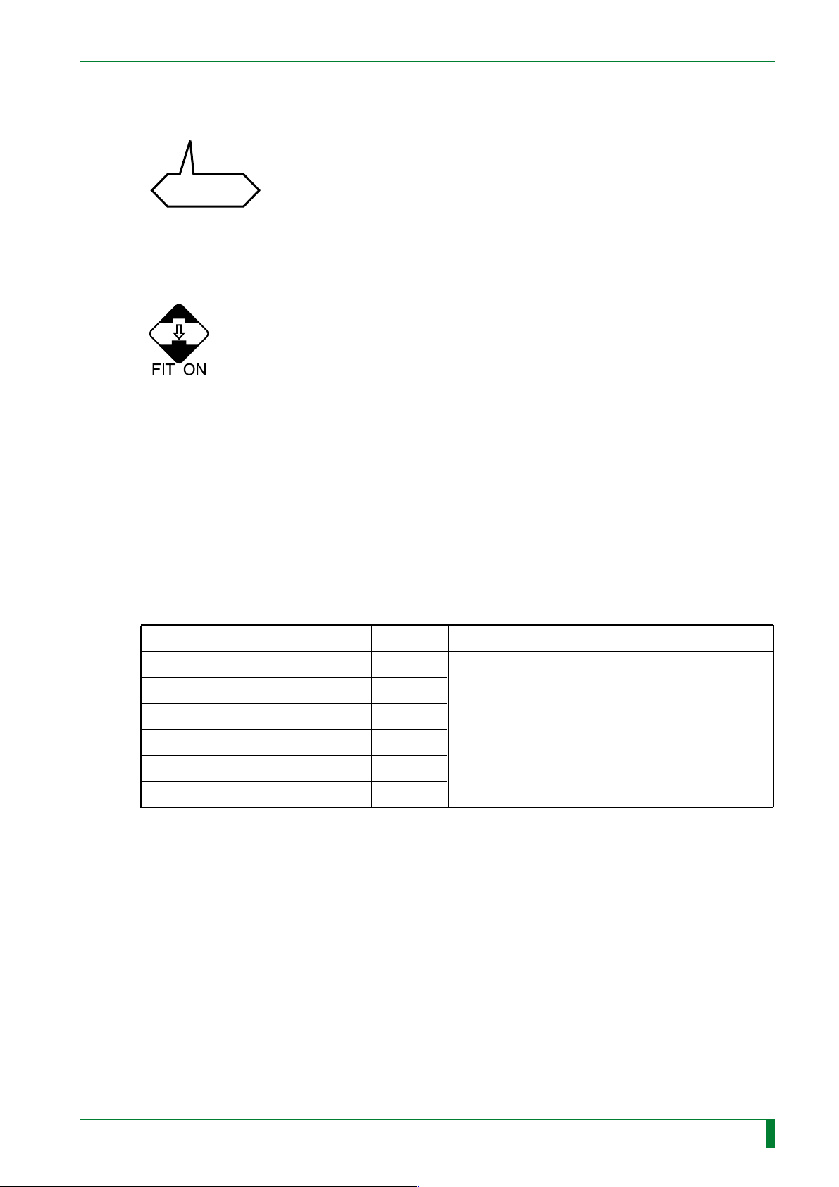
● Instruments and tools that require inspection/calibration
Name
Dosimeter
Steel rule (150mm)
Steel rule (300mm)
Digital tester
Calipers
Push-pull gauge
✻: A block gauge for use in inspection requires calibration.
Inspection Calibration Servicing instrument inspection/calibration manual No.
–
❍
❍
❍
❍ (✻)
❍
❍
–
–
ECO NO. FCR - A014
❍
–
❍
TR7H0002.EPS
009-058-02
009-058-00
08.30.2001 FM3142
10.10.2000 FM2732
CR-IR347
Service Manual
0.3
Page 6

2. Safety Precautions
Warnings and cautions regarding the procedures should be observed to avoid possible
physical hazards and serious accidents that may occur during installation and servicing.
Labels that describe relevant precautions are attached on the machine.
The instructions on such labels should also be observed during procedures.
2.1 Working Precautions
■ Power Supply
● Unless otherwise instructed in the Service Manual, be sure to turn OFF the power of the
machine and unplug the power plug before servicing. With the power plug still plugged,
you may experience electric shock, burn, or secondary damage due to short circuit even
when the machine is powered OFF. It should be noted, however, that some servicing
procedures, such as voltage measurement, cannot be performed under power-OFF
condition. In such cases, use due care to avoid electric shock, burn, or secondary
damage due to short circuit, as instructed in this manual.
0.4
● To restart or reboot the machine, power it OFF and wait more than five seconds before
powering it ON again. If the machine is powered ON within five seconds, it may
automatically shut down for protection against overcurrent and overvoltage.
■ Drive Mechanism
● Be sure to turn OFF the power before servicing the gears, cams, belts, and other drive
mechanism parts. Otherwise, your body or clothing may be entangled.
However, there may be cases where the procedures cannot be performed under power-
OFF condition. In such cases, use due care to avoid entanglement of your hand, foot,
hairs, and clothing with any rotating mechanism, as instructed in this manual.
■ Heavy Objects
Exercise due care regarding your working posture to avoid back pain during removal and
installation of heavy objects.
■ Safety Devices
Safety devices (such as fuses, circuit breakers, interlock switches, panels, and covers)
should always be enabled. Never attempt to make any alteration or modification that may
impair their safety features.
009-058-00
10.10.2000 FM2732
CR-IR347
Service Manual
0.4
Page 7

■ Optical Parts
Observe the following rules when servicing the optical parts. Otherwise, the image quality
may be degraded.
● Before removing the protective housings, be sure to turn OFF the high-voltage switch (HV
switch). If the machine is powered ON with any of the protective housings removed, the
photomultiplier will be damaged.
● Never remove the scanning optics unit covers. If the covers are removed, the image
quality may degrade.
● For dust removal procedures, observe the instructions described in the manual.
● Some high-voltage parts, such as the photomultiplier, may not be sufficiently discharged
even after power is turned OFF. When servicing such parts, exercise due care to avoid
electric shock hazards (not to touch the connector and terminal carelessly).
■ Other Working Precautions
● Do not remove or install any part or component while the machine is powered, because of
possible electric shock hazards.
● When performing checks or adjustments under the powered condition, exercise due care
against electric shock or other hazards.
0.5
● Do not touch the parts (such as erasure lamps) that remain at high temperature because
you may suffer burns.
● When servicing the scanning optics unit and printed circuit boards, be sure to wear an
antistatic wristband to remove static electricity built on the human body. Static electricity
may cause damage to the printed circuit boards.
● Secure the machine onto the floor in place by use of its adjustable feet or retainers.
● Keep clean the product labels, safety standards labels, product serial number indications,
and so forth attached on the machine, and do not peel them or put another label over
them.
● Before powering ON the machine after completion of the servicing procedures, make sure
that all the parts, screws, connectors, and so forth that were removed have been reinstalled as appropriate, and that no tool is left in the machine.
009-058-00
10.10.2000 FM2732
CR-IR347
Service Manual
0.5
Page 8

2.2 Precautions Against Laser Radiation
As indicated by the Certification and Indication Label attached on the rear cover of the
machine for overseas use, the machine complies with the U.S. Federal Regulations
concerning laser safety. The image reader incorporates a laser with a maximum output of 60
mW (Class 3B, semiconductor laser wavelength of 660 nm, red visible light), but you will not
be exposed to any hazard if you perform tasks as instructed in this manual.
■ Precautions Against Laser Exposure
Observe the following precautions to avoid laser exposure.
● Procedures that require precautions against laser exposure
When performing the following procedures, observe the instructions exactly as described
in this manual to avoid laser exposure. After the procedures are completed, put the
removed protective housings and screws back exactly in their original position to prevent
leakage of a laser beam out of the machine.
• Removal and reinstallation of the scanning optics unit.
• Replacement and cleaning of subscanning unit parts.
● Preventive maintenance for keeping the machine in compliance
0.6
In order to keep the machine in compliance, perform preventive maintenance programs
described in “Preventive Maintenance Volume” at intervals specified.
● Things that should not be done to avoid laser exposure
Observe the following precautions to avoid laser exposure.
• Never attempt to perform procedures other than instructed in this manual because you
may be exposed to laser beam radiation.
• Do not reflect a laser beam by placing a mirror or the like in the laser beam path.
• Do not alter the light path of a laser beam.
• Do not replace optical parts while the laser is energized.
• Do not attempt to make optical axis adjustment in the field. Although the semiconductor
laser beam is red visible light, field adjustment of the optical axis cannot be done.
009-058-00
009-058-00
10.10.2000 FM2732
10.10.2000 FM2732 (1)
CR-IR347
Service Manual
0.6
Page 9
■ Protective Housings Against Laser Exposure
Even when the protective housings are removed for servicing, laser beams will never leak
out from the machine unless the optical path is intentionally changed. However, if the optical
path is changed inadvertently during optics-related procedures, the service engineer or other
people around the machine may be possibly exposed to laser radiation. During opticsrelated procedures, carefully perform the procedures while checking the instructions
described in this manual, and after the procedures are completed, restore the protective
housings removed back exactly where they were.
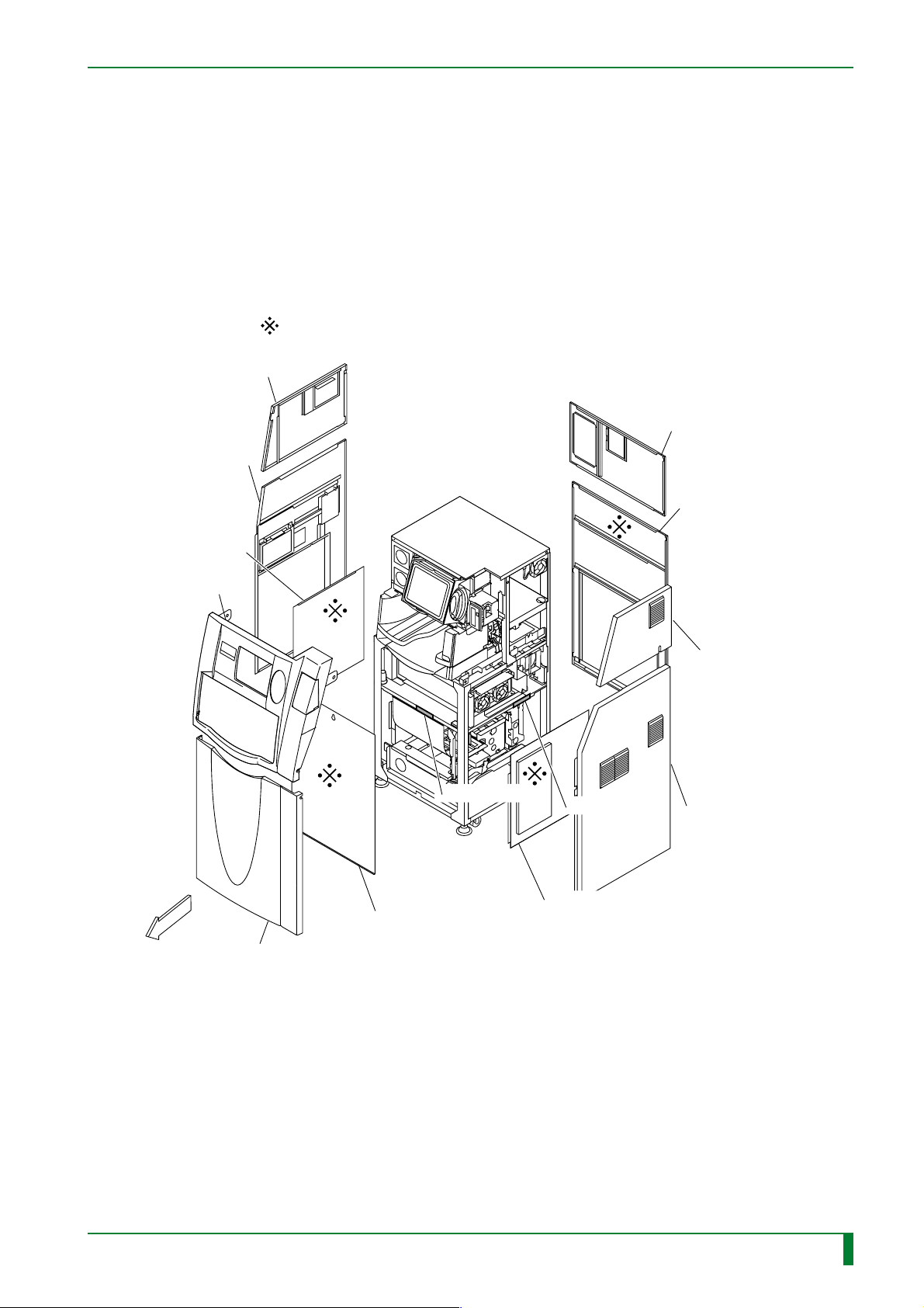
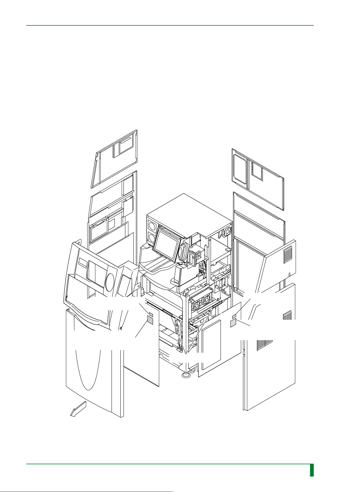
● Protective Housing of the Machine
The removable protective housings of the machine are illustrated below. The four covers
marked by
Upper left-hand side cover
Lower left-hand side cover
in the illustration below are protective housings against laser exposure.
0.7
Upper rear cover
Left-hand inner cover
Upper front cover
FRONT
Lower front cover
HHS label #2
Light protect plate
HHS label #2
Right-hand inner cover
Lower rear cover
Upper right-hand side cover
Lower right-hand side cover
FR7H0001.EPS
009-058-00
10.10.2000 FM2732
CR-IR347
Service Manual
0.7
Page 10
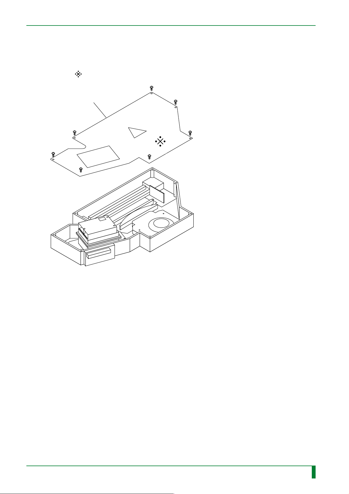
■ Scanning optics unit protective housing
The removable protective housing for the scanning optics unit is shown below. The
protective housing for laser radiation exposure prevention consists of the cover that is
marked
in the figure below.
Top cover
0.8
FR7H0015.EPS
009-058-00
10.10.2000 FM2732
CR-IR347
Service Manual
0.8
Page 11

BLANK PAGE
0.9
009-058-00
10.10.2000 FM2732
CR-IR347
Service Manual
0.9
Page 12
2.3 Safety Labels and Other Labels
2.3.1 Laser Precaution Labels
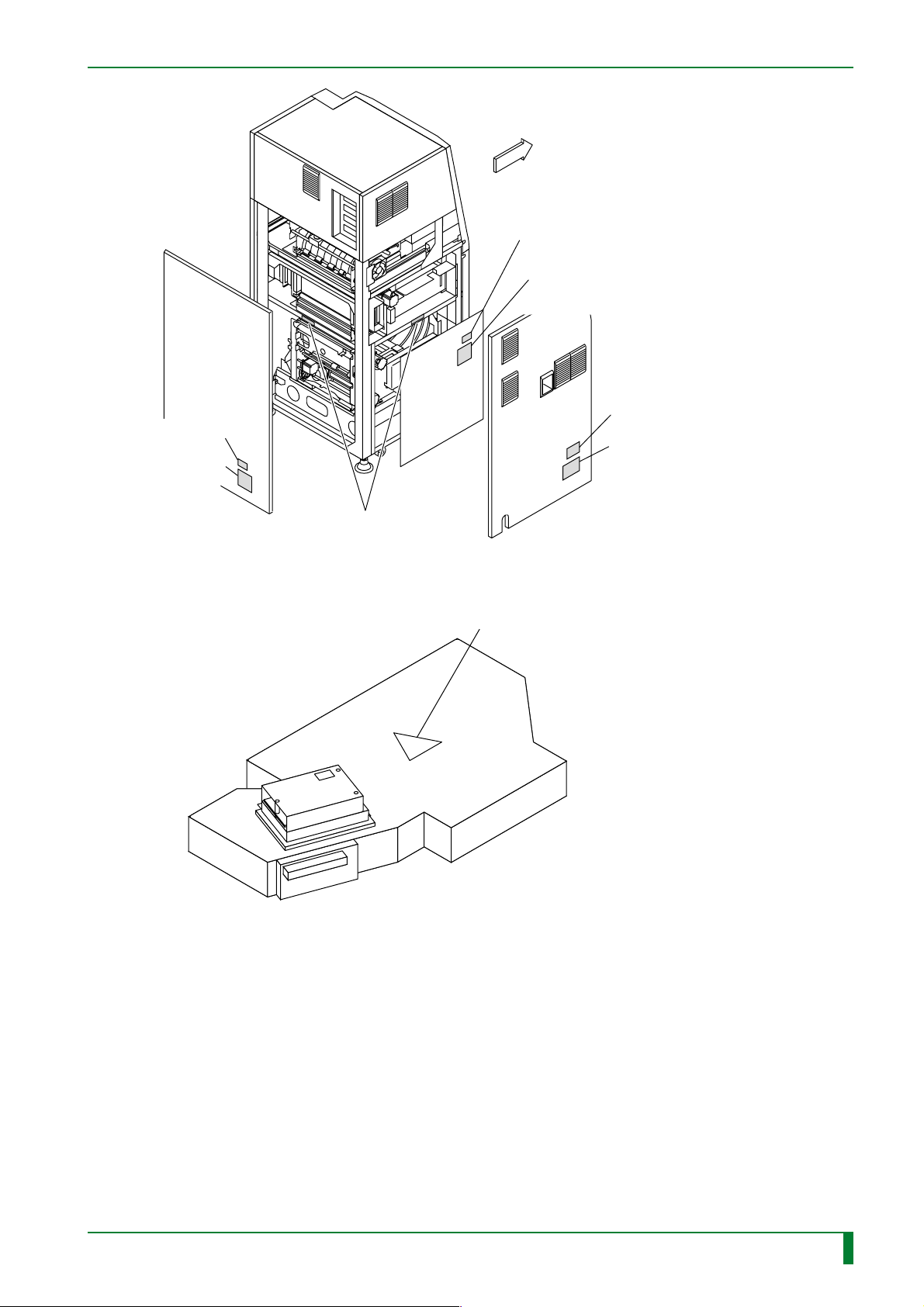
■ Precaution Label Attachment Locations
Below are illustrated the protective housings and attachment locations of laser precaution
labels, as specified in Part 1-J, Federal Regulations Code “Title 21” issued by the FDA of the
U.S.
● Machine
0.10
EN 60825-1: 1996
Class 3B panel label
FRONT
HHS label #1
HHS label #1
EN 60825-1: 1996
Class 3B panel label
HHS label #2
FR7H0002.EPS
009-058-00
10.10.2000 FM2732
CR-IR347
Service Manual
0.10
Page 13
HHS label #1
EN 60825-1: 1996
Class 3B panel label
0.11
FRONT
HHS label #1
EN 60825-1: 1996
Class 3B panel label
HHS certification and identification label
EN 60825-1: 1996
Class 1 product label
HHS label #2
● Scanning Optics Unit
FR7H0003.EPS
EN 60825-1: 1996 warning label
FR7H0015.EPS
009-058-00
10.10.2000 FM2732
CR-IR347
Service Manual
0.11
Page 14
Safety Precautions
26-30, NISHIAZABU 2-CHOME, MINATO-KU,
26-30, NISHIAZABU 2-CHOME, MINATO-KU,
■ List of Precaution Labels
● HHS Certification and Identification Label
CR-IR347 CR-IR347P
0.12
FUJI PHOTO FILM CO., LTD.
26-30, NISHIAZABU 2-CHOME, MINATO-KU,
TOKYO 106-8620, JAPAN
MODEL
SERIAL No.
MANUFACTURED
This product complies with
21 CFR Chapter 1. Subchapter J.
CR-IR 347
● HHS Label #1
DANGER
Laser radiation when open
AVOID DIRECT EXPOSURE TO BEAM
● HHS Label #2
DANGER
Laser radiation
when open external cover
AVOID DIRECT EXPOSURE TO BEAM
FPE
FR7H0004.EPS
FR7H0005.EPS
FR7H0006.EPS
FUJI PHOTO FILM CO., LTD.
26-30, NISHIAZABU 2-CHOME, MINATO-KU,
TOKYO 106-8620, JAPAN
MODEL
SERIAL No.
MANUFACTURED
This product complies with
21 CFR Chapter 1. Subchapter J.
CR-IR 347P
FIT
FR7H0021.EPS
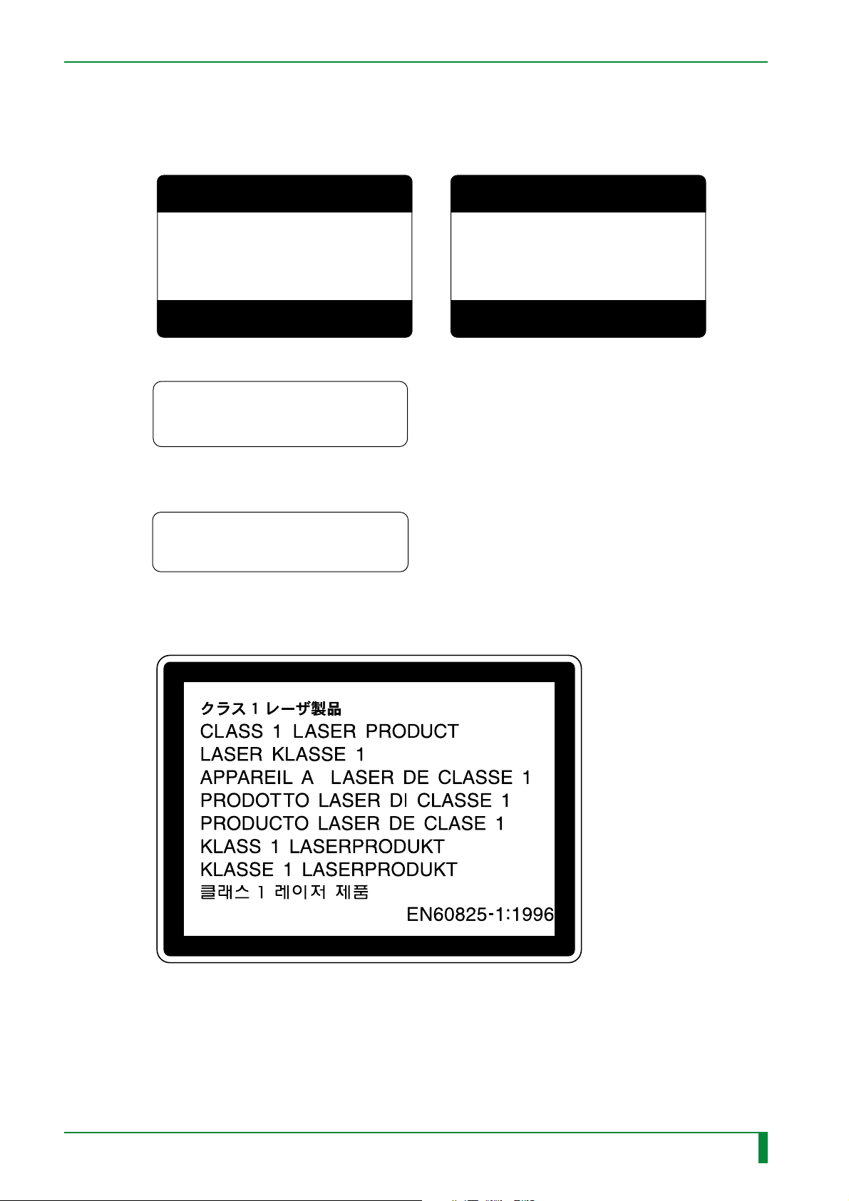
● EN 60825-1: 1996 Class 1 Product Label
FR7H0007.EPS
009-058-03
08.30.2002 FM3476
CR-IR347
Service Manual
0.12
Page 15
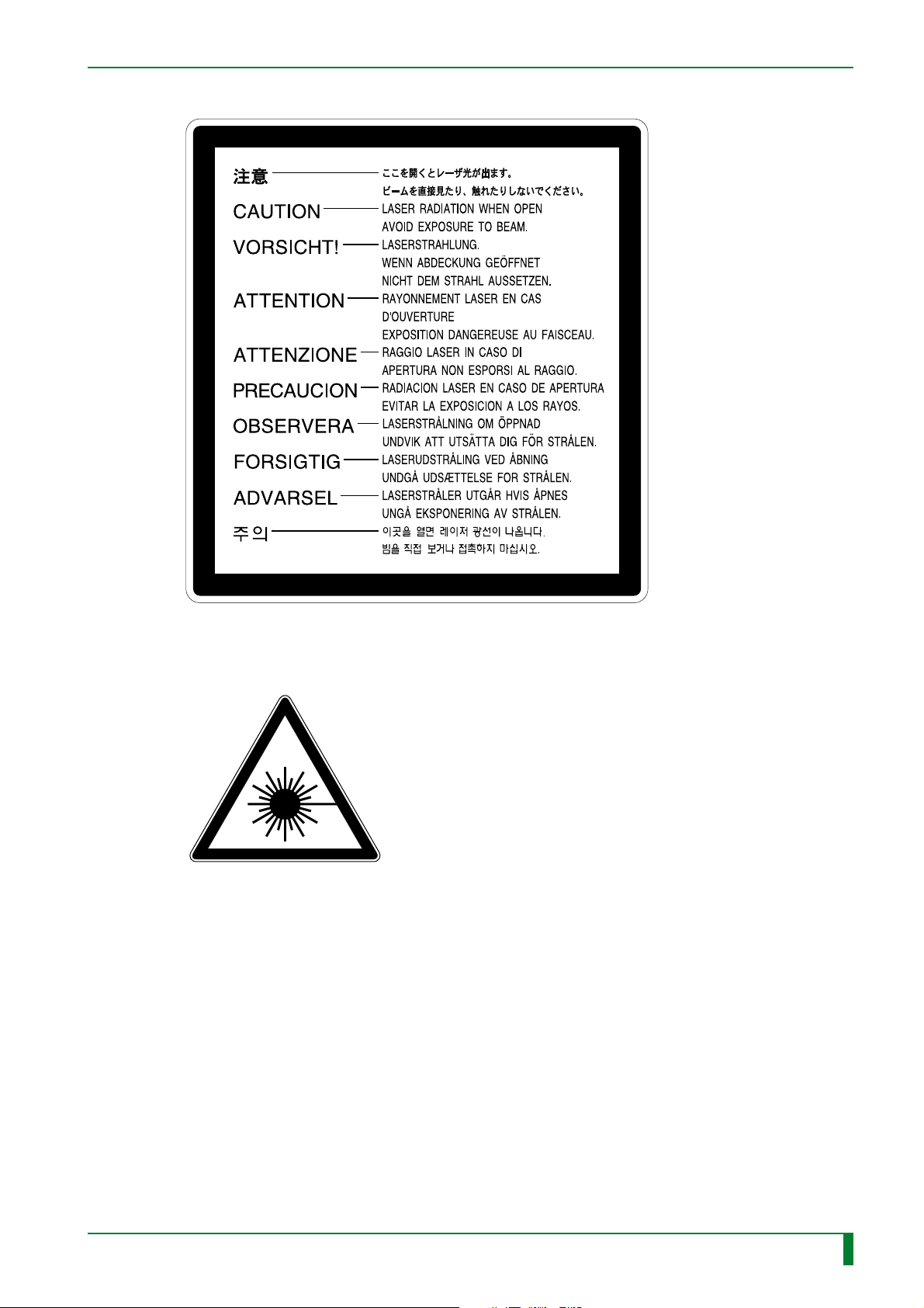
● EN 60825-1: 1996 Class 3B Panel Label
0.13
● EN 60825-1: 1996 Warning Label
FR7H0016.EPS
FR7H0008.EPS
009-058-00
10.10.2000 FM2732
CR-IR347
Service Manual
0.13
Page 16
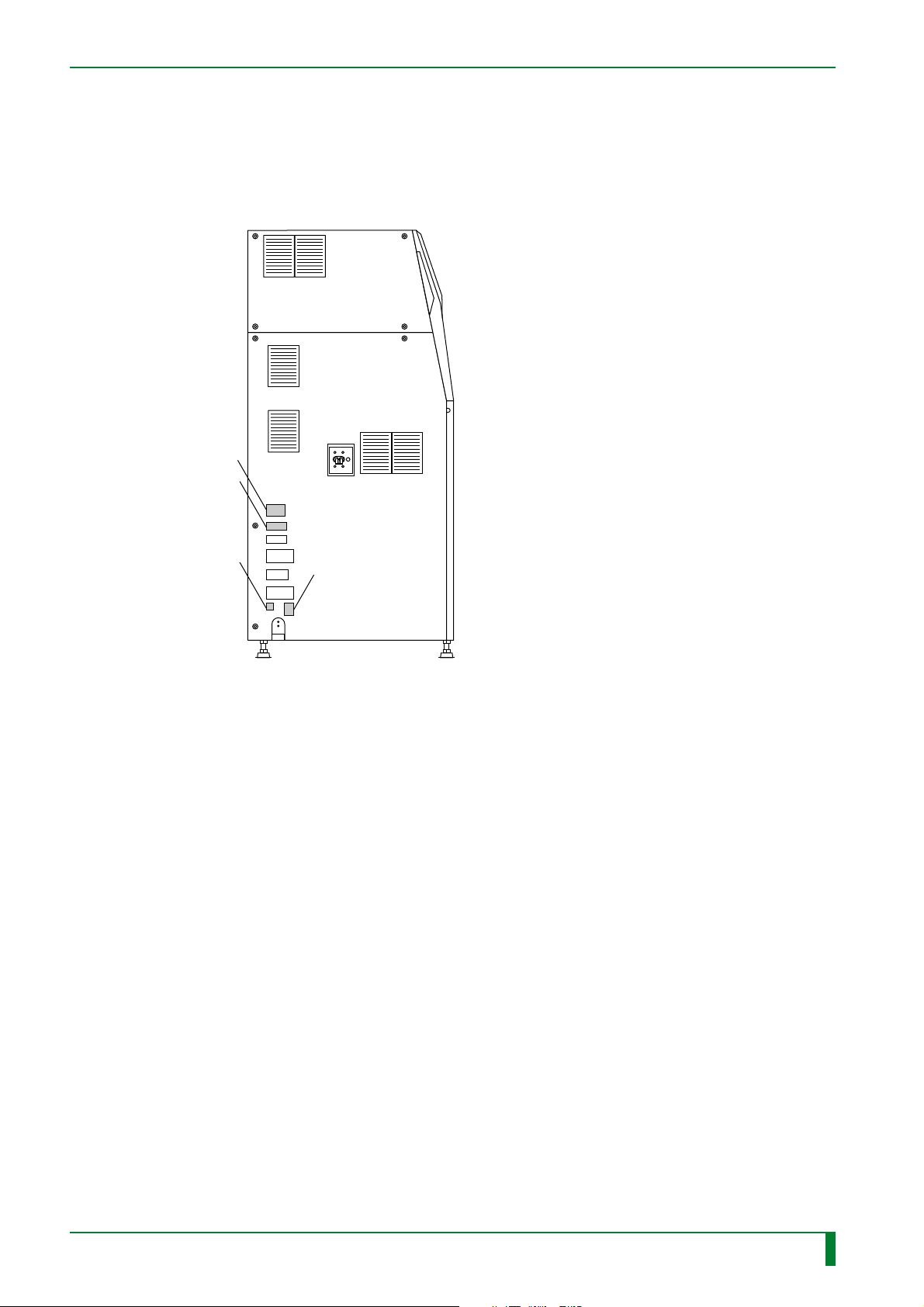
2.3.2 Other Labels
■ Label Attachment Locations
Left-hand side
Rating indication label
Manufacturer label
0.14
Compliance sticker
Electric shock
caution label
FR7H0009.EPS
009-058-00
10.10.2000 FM2732
CR-IR347
Service Manual
0.14
Page 17

Safety Precautions
■ List of Other Labels
● Ratings Indication Label
CR-IR347 CR-IR347P
0.15
● Manufacturer Label
FR7H0011.EPS
● Compliance sticker
EXAMINED
GOOD
FUJI KIKI
FR7H0012.EPS
● Electric shock caution label
FR7H0010E.EPS
FR7H0022E.EPS
009-058-03
08.30.2002 FM3476
FR7H0013.EPS
CR-IR347
Service Manual
0.15
Page 18

3. Specifications of the Machine
3.1 Dimensions, Weight, and Center of Gravity
■ Dimensions
W730xD700xH1565 (mm)
730
0.16
■ Weight
280 kg approx.
■ Center of Gravity
Height: 720 mm
From the right-hand side: 365 mm
From the rear: 385 mm
700
1565
Unit: mm
FR7H0018.EPS
009-058-00
009-058-00
10.10.2000 FM2732
10.10.2000 FM2732 (1)
CR-IR347
Service Manual
0.16
Page 19

3.2 Machine Moving and Fixing Means
■ Moving Means
• Caster x 4 (omnidirectional, no brake attached)
■ Fixing Means
• Adjustable foot x 4
3.3 Environmental Requirements
■ Atmospheric Requirements
Operation Non-operation During transit
Temperature
Relative
humidity
Atmospheric
pressure
15–30 °C0–45 °C -10–50 °C
40–80 %
700–1,030 hPa 500–1,030 hPa
10–90 % 10–90 %
(Without condensation)
0.17
The above environmental requirements during non-operation
and during transit do not apply to IPs (Imaging Plates).
■ Floor (Installation Area) Vibration Requirements
10 to 55 Hz in frequency and 0.0075 mm or less in amplitude.
■ Floor Levelness
10 mm/m (1/100 of inclination) or less for both front and rear and both right and left
■ Floor Flatness
10 mm or less
■ Variable Magnetic Field
0.3 gauss p-p or less
TR7H0001.EPS
009-058-00
009-058-00
10.10.2000 FM2732 (1)
10.10.2000 FM2732
CR-IR347
Service Manual
0.17
Page 20

3.4 Electrical Specifications
■ Frequency
50Hz/60Hz, single-phase, common specification
■ Line Voltage
120-240 V A C ±10%
■ Power Capacity
0.8 kVA
■ Power Cord
100 V: 3.5 m.
200 V: 15 m.
■ Rated Amperage
120-240 VAC, 50/60Hz: 6.7A-3.3A
0.18
■ Overload Protection
100 V/200 V: 15 A.
■ Power Consumption
0.8 kVA.
■ Grounding (Overseas)
Use a separate cable kit specifically designed for local use, and securely insert the power
plug into an indoor polarized receptacle.
3.5 Other Specifications
■ Maximum Heat Generation
800 wh.
■ Noise
Standby: 55 dB or less.
Operation: 60 dB or less
Single-shot noise: 70 dB or less
■ Warm-up Time
Approx. 4 minutes.
009-058-02
009-058-00
08.30.2001 FM3142
10.10.2000 FM2732
CR-IR347
Service Manual
0.18
Page 21

3.6 Installation and Servicing Spaces
■ Installation space requirements
The space required for installation varies depending on whether the machine is anchored.
● When the machine is not anchored ● When the machine is anchored
Height: 1800 or more
Height: 1800 or more
0.19
Rear
Machine
Front
50 or more
700 or more
■ Servicing space requirements
Furnish the following space for servicing purposes.
Height: 1900 or more
Rear
700 or more
Rear
700 or more 700 or more200 or more 200 or more
Machine
Front
100 or more
700 or more
Unit: mm
FR7H0019.EPS
600 or more
Front
Machine
700 or more
700 or more
Unit: mm
FR7H0020.EPS
009-058-00
10.10.2000 FM2732
CR-IR347
Service Manual
0.19
Page 22

3.7 Preliminary W ork
Before starting the grounding procedures, make sure that the place where the machine is to
be installed meets the criteria set forth in “SSS Installation Site Requirements.”
Before the machine is transferred, preinstallation procedures should be completed for necessary electrical utility, water supply/drain piping, waste solution disposal, and air-conditioning
system installation work.
■ Electrical Work (Overseas)
For more detail, local rules and regulations should be complied with.
● For 200V power supply
An independent branch circuit assigned specifically for the machine should be provided via a
15A circuit breaker .
A predetermined ground wiring should be implemented for the ground polarity of the recep-
tacle.
● For 100V power supply
A predetermined ground wiring should be implemented for the ground polarity of the recep-
tacle.
0.20
■ Installation site conditions
Avoid the following installation sites:
• Places where the temperature changes drastically
• Places near heat sources such as heaters
• Places where water leakage or equipment submersion may occur
• Places where any corrosive gas ma y be generated
• Dusty places
• Places where the machine is subject to constant or excessive vibration/shock
• Places exposed to direct sunlight
009-058-02
009-058-00
08.30.2001 FM3142
10.10.2000 FM2732
CR-IR347
Service Manual
0.20
Page 23

BLANK PAGE
0.21
009-058-00
10.10.2000 FM2732
CR-IR347
Service Manual
0.21
Page 24

Notation of Board Names in Manual
4. Notation of Board Names in Manual
Information about modifications to the boards installed in the machine is summarized here.
Unless spelled out or enumerated in the manual, board names shall be replaced as follows.
0.22
Change to boards installed
MTH08C → MTH08D
MMA90A → DIM08A
MMB90A → DIM08A
CPU90F → LAN90B
Summary of change
● Features of the MTH08D board
• DIP switch (S1) was added.
• The fuse was changed to a replaceable glass tube type.
• The subject to be protected by the fuse was changed.
● Features of the DIM08A board
• Memory module for the MTH08D board.
• The procedure for its removal/reinstallation was changed
to horizontal detachment.
• Shipped as installed in the machine.
● Features of the LAN90B board
• To install the LAN90B board, it is necessary that the bracket
located on the rear side of the controller be version D or later.
TR7H0003.EPS
009-058-03
08.30.2002 FM3476
CR-IR347
Service Manual
0.22
Page 25

BLANK PAGE
0.23
009-058-03
08.30.2002 FM3476
CR-IR347
Service Manual
0.23
Page 26

Contents Maintenance Machine Description
CR-IR347 Service Manual – Contents
Machine Description (MD)
1. Machine Overview ........................................................................................................ MD-2
1.1 Features .............................................................................................................. MD-2
1.2 System Configuration........................................................................................ MD-4
1.3 External Machine Components and Their Names .......................................... MD-10
1.4 Internal Machine Components.......................................................................... MD-12
1.4.1 Unit arrangement ................................................................................... MD-12
1.4.2 Roller arrangement and conveyance path .......................................... MD-13
1.4.3 I/O arrangement diagram and function descriptions ......................... MD-14
1.4.4 PC board arrangement diagram ........................................................... MD-18
1.5 System Block Diagram ...................................................................................... MD-20
0.24
1.6 Power Supply Related Fuse Block Diagram.................................................... MD-22
2. Software ........................................................................................................................ MD-26
2.1 Software Terms and Definitions ....................................................................... MD-26
2.2 Image Data Flow (1) ........................................................................................... MD-28
2.3 Image Data Flow (2) ........................................................................................... MD-30
2.4 Startup Control Descriptions ............................................................................ MD-34
3. Electrical ....................................................................................................................... MD-36
3.1 Power supply unit (JPS-6)................................................................................. MD-36
3.2 Erasure Unit........................................................................................................ MD-38
3.3 Information on Board LEDs .............................................................................. MD-40
4. Scanner ......................................................................................................................... MD-44
4.1 Scanner Components ........................................................................................ MD-45
4.2 Scanner Operation Descriptions ...................................................................... MD-46
5. Mechanical .................................................................................................................... MD-48
5.1 Cassette Set Unit ............................................................................................... MD-50
5.2 IP removal unit ................................................................................................... MD-51
5.3 Erasure Conveyor ........................................................................................... MD-51.2
5.4 Side-Positioning Conveyor .............................................................................MD-51.3
5.5 Subscanning Unit ............................................................................................ MD-51.5
009-058-03
08.30.2002 FM3476
CR-IR347
Service Manual
0.24
Page 27

Contents Maintenance Machine Description
6. ***This chapter is intentionally blank*** ................................................................... MD-51.9
7. ***This chapter is intentionally blank*** ................................................................. MD-51.11
8. Mechanical Control Flowcharts .................................................................................. MD-52
8.1 Viewing the Control Flowcharts ....................................................................... MD-52
8.2 Normal Operation Flowcharts........................................................................... MD-54
8.2.1 Cassette insertion .................................................................................. MD-56
8.2.2 IP feed ..................................................................................................... MD-62
8.2.3 IP length measurement ......................................................................... MD-70
8.2.4 IP Identification ...................................................................................... MD-74
8.2.5 Cleaning guide grip ............................................................................... MD-78
0.25
8.2.6 Side-Positioning Conveyance .............................................................. MD-80
8.2.7 Cleaning Guide Grip Release ............................................................... MD-84
8.2.8 Side-positioning ..................................................................................... MD-88
8.2.9 CSL/IDT information confirmation ....................................................... MD-92
8.2.10 Preparations for reading ....................................................................... MD-94
8.2.11 Reading ................................................................................................... MD-96
8.2.12 CSL/IDT information confirmation 2 ....................................................MD-104
8.2.13 After-reading conveyance ..................................................................... MD-106
8.2.14 Before-erasure conveyance .................................................................. MD-108
8.2.15 Erasure conveyance ..............................................................................MD-112
8.2.16 After-erasure conveyance ..................................................................... MD-114
8.2.17 IP loading ................................................................................................ MD-118
8.2.18 Erasure confirmation ............................................................................. MD-124
8.2.19 Cassette ejection ...................................................................................MD-126
8.3 Secondary Erasure Flowcharts ........................................................................MD-128
8.3.1 Backward loading ..................................................................................MD-130
009-058-03
08.30.2002 FM3476
CR-IR347
Service Manual
0.25
Page 28

Contents Maintenance Machine Description
8.4 Step Operation Flowcharts ...............................................................................MD-132
8.4.1 Feed/load step operation ...................................................................... MD-132
8.4.2 Side-positioning step operation ...........................................................MD-142
8.5 Initialization Flowcharts ....................................................................................MD-146
8.5.1 Side-positioning grip home positioning ..............................................MD-148
8.5.2 Side-positioning unit home positioning ..............................................MD-152
8.5.3 Mirror ascent ..........................................................................................MD-156
8.5.4 Initialization subscanning grip confirmation ...................................... MD-158
8.5.5 Cleaning guide HP positioning .............................................................MD-162
8.5.6 IP search ................................................................................................. MD-166
8.5.7 Suction cup HP positioning .................................................................. MD-176
0.26
8.5.8 Feed/load conveyance IP processing .................................................. MD-180
8.5.9 Cassette hold release confirmation .....................................................MD-184
8.5.10 Before-reading standby IP processing ................................................MD-188
8.5.11 Subscanning grip HP positioning ........................................................ MD-194
8.5.12 Empty cassette ejection ........................................................................MD-204
8.5.13 Mirror descent ........................................................................................MD-206
8.5.14 Initialization cassette hold release ....................................................... MD-208
8.6 Abnormality Process Flowcharts ..................................................................... MD-210
8.6.1 Abnormality process (cassette ejection 1) ..........................................MD-210
8.6.2 Abnormality process (cassette ejection 2) ..........................................MD-212
8.6.3 Abnormality process (cassette not detected) ..................................... MD-216
8.6.4 Abnormality process (recovered IP loading) ...................................... MD-217
8.6.5 Abnormality process (high dose) .........................................................MD-218
8.6.6 Abnormality process (IP generation/type mismatch detection) ........MD-219
8.6.7 Abnormality process (lamp failure) ..................................................... MD-220
8.6.8 Abnormality process (IDT line failure) ................................................. MD-221
8.6.9 Abnormality process (ID information not registered) ........................ MD-222
009-058-03
08.30.2002 FM3476
8.6.10 Abnormality process (BCR retry) .........................................................MD-223
CR-IR347
Service Manual
0.26
Page 29

Contents Maintenance Machine Description
BLANK PAGE
0.27
009-058-03
08.30.2002 FM3476
CR-IR347
Service Manual
0.27
Page 30

Contents Maintenance Troubleshooting
Troubleshooting (MT)
1. Overview of Troubleshooting ...................................................................................... MT1-1
1.1 Flow of Troubleshooting ................................................................................... MT1-1
1.2 How to Understand Error Log........................................................................... MT1-3
2. Error Codes List ........................................................................................................... MT2-1
3. Format of Detail Information ....................................................................................... MT3-1
3.1 Supplementary Explanation of Detail Information.......................................... MT3-17
3.2 Format of Abort Code ........................................................................................MT3-18
4. Error Code Analysis Flow (Mechanism)..................................................................... MT4-1
03A2, 13A1, 13A2, 23A1, 23A2 .......................................................................... MT4-1
13A4, 13A5 .......................................................................................................... MT4-2
0.28
13A6, 13A7 .......................................................................................................... MT4-3
13A8, 23A8 .......................................................................................................... MT4-4
13A9, 23A9 .......................................................................................................... MT4-5
13AA, 23AA......................................................................................................... MT4-6
13AD .................................................................................................................... MT4-7
03B1, 23B1 .......................................................................................................... MT4-8
03B2, 23B2 .......................................................................................................... MT4-9
03B3 .................................................................................................................... MT4-10
03B4, 03B5, 03B6 ...............................................................................................MT4-11
03B7 .................................................................................................................... MT4-12
03BC, 23BA, 23BB, 23BC ..................................................................................MT4-13
03BF, 23BD, 23BE, 23BF ...................................................................................MT4-14
03C1 .................................................................................................................... MT4-15
03C0, 03C2 ..........................................................................................................MT4-16
03C6, 03C8, 03CA, 23C6 .................................................................................... MT4-17
03C7, 03C9, 03CB, 23C7 .................................................................................... MT4-18
03CC ....................................................................................................................MT4-19
009-058-03
08.30.2002 FM3476
03CD ....................................................................................................................MT4-20
03D3 .................................................................................................................... MT4-22
03D5 .................................................................................................................... MT4-23
13E1, 13E2, 13E4, 13E5, 13E9, 23E1, 23E2, 23E4, 23E5, 23E9 ....................... MT4-25
13E3, 23E3 ..........................................................................................................MT4-26
03E8, 23E6, 23E7, 23E8 ..................................................................................... MT4-27
03EE, 03EF, 23EA, 23EB, 23EC, 23ED ............................................................. MT4-28
23F1, 23F2........................................................................................................... MT4-29
13F3, 23F3........................................................................................................... MT4-30
CR-IR347
Service Manual
0.28
Page 31

Contents Maintenance Troubleshooting
5. Error Code Analysis Flow (Scanner) .......................................................................... MT5-1
0532, 2542, 2570 ................................................................................................. MT5-1
0534, 1533, 2543, 2544, 2571, 2572, 2573, 2574 ............................................... MT5-2
0536, 2535, 2545, 2546 ....................................................................................... MT5-3
0537, 2547, 2575 ................................................................................................. MT5-4
0538, 2530, 2548, 2576 ....................................................................................... MT5-5
0563, 2560, 2561, 2564 ....................................................................................... MT5-6
6. Error Code Analysis Flow (Electrical) ........................................................................ MT6-1
7. Checkout Flowcharts ................................................................................................... MT7-1
7.1 Checking the SK1 .............................................................................................. MT7-2
0.29
7.2 Checking the SK2 .............................................................................................. MT7-4
7.3 Checking the SK3 .............................................................................................. MT7-6
7.4 Checking the Ground Connections.................................................................. MT7-8
7.5 Checking the SL1 ...............................................................................................MT7-10
7.6 Checking the SL2 ...............................................................................................MT7-12
7.7 Checking the SL4 ...............................................................................................MT7-14
7.8 Checking the SL5 ...............................................................................................MT7-16
7.9 Checking the SM1 ..............................................................................................MT7-18
7.10 Checking the SN1 .............................................................................................. MT7-20
7.11 Checking the SN2 .............................................................................................. MT7-22
7.12 Checking the SN3 .............................................................................................. MT7-24
7.13 Checking the SN4 .............................................................................................. MT7-26
7.14 Checking the SZ1 (SED08D) ............................................................................. MT7-28
7.15 Checking the SZ2 ...............................................................................................MT7-30
7.16 Checking the SZ3 ...............................................................................................MT7-32
7.17 Checking the SZ4 ...............................................................................................MT7-34
7.18 Checking the ML1 ..............................................................................................MT7-36
7.19 Checking the ML2 ..............................................................................................MT7-38
7.20 Checking the MM1 ............................................................................................. MT7-40
7.21 Checking the MN1 ..............................................................................................MT7-42
7.22 Checking the MN2 ..............................................................................................MT7-44
7.23 Checking the MN3 ..............................................................................................MT7-46
7.24 Checking the MN4 ..............................................................................................MT7-48
7.25 Checking the MZ1 ..............................................................................................MT7-50
7.26 Checking the MZ2 ..............................................................................................MT7-52
7.27 Checking the MZ3 ..............................................................................................MT7-54
009-058-03
08.30.2002 FM3476
CR-IR347
Service Manual
0.29
Page 32

Contents Maintenance Troubleshooting
7.28 Checking the MZ4 ..............................................................................................MT7-56
7.29 Checking the PL1 ...............................................................................................MT7-58
7.30 Checking the SVL1 ............................................................................................ MT7-60
7.31 Checking the SOLK1 ......................................................................................... MT7-62
7.32 Checking the BCRK1 .........................................................................................MT7-64
7.33 Checking the BCRN1 .........................................................................................MT7-66
7.34 Checking the Erasure Lamps (LAMP1-LAMP5) .............................................. MT7-68
7.35 Checking the Polygon (POL) ............................................................................ MT7-70
7.36 Checking the Laser (LDD) ................................................................................. MT7-72
7.37 Checking the Start Point Detector (SYN) .........................................................MT7-74
7.38 Checking the Photomultiplier (PMT08D) ......................................................... MT7-76
0.30
7.39 Checking the Photomultiplier (PMR08C) .........................................................MT7-78
7.40 Checking the Voltages ...................................................................................... MT7-80
7.41 Checking the Boards .........................................................................................MT7-82
7.42 Checking the HDD.............................................................................................. MT7-84
7.43 Checking the Monitor ........................................................................................MT7-86
8. Circuit Diagram ............................................................................................................ MT8-1
9. Priority Checks to Be Conducted upon Trouble Occurrence ................................... MT9-1
10. Making Analyses of Image Abnormalities .................................................................MT10-1
10.1 Making Analyses in Accordance with Error Codes ........................................MT10-1
10.2 Making Analyses in the Virtual Image Generation Mode ...............................MT10-1
[1] Vertical streaks ............................................................................................. MT10-2
[2] Horizontal streaks ........................................................................................ MT10-3
[3] Other image abnormalities ..........................................................................MT10-4
10.3 Reference Data - Typical Image Abnormalities ...............................................MT10-5
009-058-03
08.30.2002 FM3476
CR-IR347
Service Manual
0.30
Page 33

Contents Maintenance Troubleshooting
BLANK PAGE
0.31
009-058-03
08.30.2002 FM3476
CR-IR347
Service Manual
0.31
Page 34

Contents Maintenance Checks, Replacement and Adjustment of Parts
0.32
Checks, Replacement and Adjustment of Parts (MC)
1. Check/Adjustment Procedures for Each Unit............................................................ MC-2
2. Table of Contents ......................................................................................................... MC-4
3. Removing and Installing the Covers .......................................................................... MC-8
4. Removing and Installing the Cassette Set Unit ......................................................... MC-10
4.1 Cassette Set Unit ............................................................................................... MC-10
4.2 Shutter ................................................................................................................ MC-12
4.3 Cassette Ejection Sensor (SK1) ....................................................................... MC-14
4.4 Barcode Reader (BCRK1).................................................................................. MC-16
4.5 Pulling Out the Tray ........................................................................................... MC-20
4.6 Cassette Hold Solenoid (SOLK1) ..................................................................... MC-26
4.7 Cassette Hold Sensor (SK3) ............................................................................. MC-32
4.8 Claw Guide Assembly ....................................................................................... MC-34
4.9 Cassette IN Sensor (SK2) .................................................................................. MC-40
4.10 Rubber Roller ..................................................................................................... MC-50
4.11 Guide Plate ......................................................................................................... MC-52
4.12 Guide Stoppers .................................................................................................. MC-64
4.13 Movable Guides ................................................................................................. MC-66
5. Removing and Installing the IP Removal Unit ........................................................... MC-74
5.1 IP Removal Unit.................................................................................................. MC-74
5.2 IP Leak Valve (SVL1).......................................................................................... MC-78
5.3 Suction Cup HP Sensor (SL1)........................................................................... MC-80
5.4 Timing Belt (for IP Conveyance)....................................................................... MC-86
5.5 Guide Plate A...................................................................................................... MC-90
5.6 Rubber Rollers C and D..................................................................................... MC-92
5.7 Rubber Roller (Large) ........................................................................................ MC-94
5.8 Guide Plate D...................................................................................................... MC-96
5.9 Guide Plates B and C......................................................................................... MC-98
5.10 Supports (for IP Removal Arm) ........................................................................ MC-100
5.11 Suction Cups ......................................................................................................MC-104
5.12 IP Suction Pump (PL1) ...................................................................................... MC-108
5.13 Inch/Metric Sensor (SL4) ...................................................................................MC-110
5.14 Suction Sensor (SL5)......................................................................................... MC-112
5.15 Receiver Rollers .................................................................................................MC-114
5.16 Guide Plates E, F, and G ................................................................................... MC-118
5.17 Suction Cup Driving Motor (ML1) .....................................................................MC-120
009-058-03
08.30.2002 FM3476
CR-IR347
Service Manual
0.32
Page 35

Contents Maintenance Checks, Replacement and Adjustment of Parts
5.18 Timing Belt (for Suction Cup Drive) ................................................................. MC-122
5.19 Shaft (for Suction Cup Drive)............................................................................ MC-124
5.20 IP Removal Unit Upper Assembly ....................................................................MC-128
5.21 Rubber Roller A.................................................................................................. MC-130
5.22 IP Transport Motor (ML2) ..................................................................................MC-132
5.23 Shaft (for IP Conveyance) .................................................................................MC-134
5.24 Rubber Roller B.................................................................................................. MC-136
6. Removing and Installing the Erasure Conveyor ....................................................... MC-138
6.1 Erasure Lamp Assembly ...................................................................................MC-138
6.2 Erasure Conveyor ..............................................................................................MC-140
0.33
6.3 Cleaning Roller Assembly................................................................................. MC-144
6.4 Cleaning Rollers................................................................................................. MC-146
6.5 Erasure Lamps (LAMP1-LAMP5) ......................................................................MC-148
6.6 Erasure Thermostatic Switch (TSW2) ..............................................................MC-150
6.7 Erasure Thermostatic Switch (TSW1) ..............................................................MC-152
6.8 Erasure Cooling Fan (FANM1) ..........................................................................MC-154
6.9 Sockets ...............................................................................................................MC-156
6.10 Timing Belts ....................................................................................................... MC-160
6.11 Lamp House Assembly ..................................................................................... MC-164
6.12 Filter ....................................................................................................................MC-166
6.13 Reflection Plate .................................................................................................. MC-168
6.14 IP Transport Motor (MM1) ................................................................................. MC-170
6.15 Rubber Rollers (Upper) ..................................................................................... MC-172
6.16 Light Protect Plates ...........................................................................................MC-174
6.17 Rubber Rollers (Lower) .....................................................................................MC-176
6.18 Guide Plates .......................................................................................................MC-178
7. Pulling Out and Pushing In the Scanner Unit ............................................................MC-182
009-058-03
08.30.2002 FM3476
CR-IR347
Service Manual
0.33
Page 36

Contents Maintenance Checks, Replacement and Adjustment of Parts
8. Removing and Installing the Side-Positioning Conveyor ......................................... MC-188
8.1 Side-Positioning Conveyor ...............................................................................MC-188
8.2 Grip Release Motor (MN2) ................................................................................. MC-192
8.3 Barcode Reader (BCRN1).................................................................................. MC-194
8.4 Side-Positioning Mechanism HP Sensor (SN1) .............................................. MC-196
8.5 Grip Release HP Sensor (SN2) ......................................................................... MC-198
8.6 Cleaning Guide Drive Motor (MN4)................................................................... MC-200
8.7 BCR08A Board ...................................................................................................MC-202
8.8 Side-Positioning IP Sensor (SN3)..................................................................... MC-204
8.9 Cleaning Guide HP Sensor (SN4) ..................................................................... MC-206
0.34
8.10 Cleaning Guide Assembly................................................................................. MC-208
8.11 Shaft (for Cleaning Guide Assembly) .............................................................. MC-214
8.12 Guide Plate C...................................................................................................... MC-218
8.13 Timing Belt (for IP Conveyance)....................................................................... MC-220
8.14 Guide Plate G ..................................................................................................... MC-222
8.15 Rubber Rollers (Rear) ........................................................................................MC-226
8.16 Wires (Left Side)................................................................................................. MC-230
8.17 Wires (Right Side) ..............................................................................................MC-234
8.18 Timing Belt (for Side-Positioning Mechanism) ...............................................MC-240
8.19 Shaft (for Grip Release) .....................................................................................MC-246
9. Removing and Installing the Scanning Optics Unit .................................................. MC-250
9.1 Adjusting the Format .........................................................................................MC-250
9.2 Shading and Sensitivity Corrections ...............................................................MC-254
9.3 Checking for Image Problems ..........................................................................MC-258
9.4 Removing and Installing the Scanning Optics Unit........................................ MC-262
9.5 LD Assembly ......................................................................................................MC-266
9.6 Polygon Assembly .............................................................................................MC-270
9.7 SYN08A Board.................................................................................................... MC-274
009-058-03
08.30.2002 FM3476
CR-IR347
Service Manual
0.34
Page 37

Contents Maintenance Checks, Replacement and Adjustment of Parts
0.35
10. Removing and Installing the Subscanning Unit ........................................................MC-278
10.1 Driving-Side Grip Release HP Sensor (SZ2).................................................... MC-278
10.2 Mirror HP Sensor (SZ4) ..................................................................................... MC-280
10.3 Rubber Belt and SUS Belt ................................................................................. MC-282
10.4 Kapton® Belt ......................................................................................................MC-284
10.5 Flywheel ..............................................................................................................MC-286
10.6 Subscanning Motor MZ1 (FFM) ........................................................................ MC-288
10.7 PMT08D Board ................................................................................................... MC-292
10.8 PMR08C Board ................................................................................................... MC-296
10.9 Light-Collecting Guide Assembly (for Front Surface) ....................................MC-300
10.10 Light-Collecting Guide Assembly (for Back Surface) .................................... MC-308
10.11 Light-Collecting Mirror and IP Leading-Edge Sensor (SZ1/SED08D) ........... MC-320
10.12 Glass Guide ........................................................................................................ MC-326
10.13 Lower Rubber Rollers........................................................................................ MC-332
10.14 Mirror Driving Motor (MZ4)................................................................................ MC-336
10.15 Driving-Shaft Grip Motor (MZ2) ........................................................................ MC-338
10.16 Driven-Shaft Grip Motor (MZ3).......................................................................... MC-342
10.17 Driven-Side Grip Release HP Sensor (SZ3) .....................................................MC-346
10.18 Subscanning Unit Controller Assembly ..........................................................MC-348
10.19 SCN08D/SCR08D Board ....................................................................................MC-354
10.20 PHV08D Board.................................................................................................... MC-358
11. Removing and Installing the Hard Disk Drive (HDD) ................................................ MC-360
11.1 Setting HDD ........................................................................................................ MC-361
11.2 Hard Disk Drive (HDD) ....................................................................................... MC-362
12. Removing and Installing the Floppy Disk Drive (FDD) .............................................MC-372
12.1 Setting FDD ........................................................................................................ MC-372
12.2 Floppy Disk Drive (FDD) ....................................................................................MC-372
009-058-03
08.30.2002 FM3476
CR-IR347
Service Manual
0.35
Page 38

Contents Maintenance Checks, Replacement and Adjustment of Parts
0.36
13. Removing and Installing the Power Supply Unit (JPS-6) .........................................MC-374
13.1 Power Supply Unit (JPS-6) ................................................................................MC-374
13.2 Power Supply Unit Fuses ..................................................................................MC-378
14. Removing and Installing the Monitor .........................................................................MC-382
14.1 CRT (Monitor) .....................................................................................................MC-382
14.2 Fuse Between Power Supply Unit and CRT ....................................................MC-388
15. Removing and Installing the PC Boards .................................................................... MC-390
15.1 MTH08C Board ...................................................................................................MC-402
15.2 MTH08D Board ...................................................................................................MC-404
15.3 CPU90E Board.................................................................................................... MC-406
15.4 IMG07B Board ....................................................................................................MC-410
15.5 BSP08A Board.................................................................................................... MC-411
15.6 IMG08M Board ....................................................................................................MC-413
15.7 CPU90F Board (Optional) ..................................................................................MC-414
15.8 LAN90B Board (Optional).................................................................................. MC-416
15.9 HCP08A Board (Optional) ................................................................................. MC-417
15.10 IMG08H Board (Optional) ..................................................................................MC-418
15.11 SNS08C and DRV08A Boards ........................................................................... MC-420
15.12 VOL08A Board.................................................................................................... MC-427
15.13 LED08A Board ....................................................................................................MC-428
15.14 LED08B Board ....................................................................................................MC-428
15.15 BCR08A Board ...................................................................................................MC-429
15.16 SYN08A, PMT08D, PMR08C, SCN08D/SCR08D, and PHV08D boards .......... MC-429
009-058-03
08.30.2002 FM3476
CR-IR347
Service Manual
0.36
Page 39

Contents Maintenance Checks, Replacement and Adjustment of Parts
BLANK PAGE
0.37
009-058-03
08.30.2002 FM3476
CR-IR347
Service Manual
0.37
Page 40

Contents Maintenance Maintenance Utility
Maintenance Utility (MU)
1. Summary of Service Utility ............................................................................................ MU-2
(1) Maintenance Utility ............................................................................................... MU-2
(2) Configuration Setting ........................................................................................... MU-2
(3) Image Processing Parameter Adjustment .......................................................... MU-2
2. Mode Transitions ............................................................................................................. MU-4
(1) Initialization process mode .................................................................................. MU-5
(2) Routine process mode ......................................................................................... MU-5
(3) Abnormality process mode.................................................................................. MU-5
(4) User utility mode (U-Utility).................................................................................. MU-5
(5) Maintenance utility mode (M-Utility) ................................................................... MU-5
0.38
(6) End process mode ................................................................................................ MU-5
3. U-Utility (User Utility) ...................................................................................................... MU-6
(1) Functions of U-Utility............................................................................................ MU-6
(2) U-Utility tree........................................................................................................... MU-6
(3) U-Utility operation ................................................................................................. MU-7
(4) U-Utility commands .............................................................................................. MU-8
4. M-Utility (Maintenance Utility) ...................................................................................... MU-10
(1) Functions of M-Utility ......................................................................................... MU-10
(2) M-Utility tree ........................................................................................................ MU-10
(3) M-Utility operation .............................................................................................. MU-16
(4) Common Operating Procedures for M-Utility................................................... MU-19
(5) M-Utility commands ............................................................................................ MU-24
[1] ERROR LOG UTILITY.......................................................................................... MU-24
[1-1] LIST ......................................................................................................... MU-24
009-058-03
08.30.2002 FM3476
[1-1-1] ALL .............................................................................................. MU-24
[1-1-2] SUMMARY .................................................................................. MU-25
[1-2] CLEAR..................................................................................................... MU-26
[1-3] SAVE TO FD ............................................................................................ MU-27
[1-3-1] ERROR LOG ............................................................................... MU-27
[1-3-2] TRACE DATA .............................................................................. MU-28
[1-3-3] IOT DATA ..................................................................................... MU-29
CR-IR347
Service Manual
0.38
Page 41

Contents Maintenance Maintenance Utility
[1-4] SAVE TO HD ............................................................................................ MU-30
[1-4-1] ERROR LOG ............................................................................... MU-30
[2] CONFIGURATION SETTING ............................................................................... MU-32
[2-1] SYSTEM (IRSET.CFG) ............................................................................MU-32
[2-2] PRINT (FILMFMT.CFG) ........................................................................ MU-45.4
[2-3] REMOTE SWITCH (RMT_SW.CFG) ....................................................... MU-55
[2-4] EQUIPMENT (EQUIP) ............................................................................. MU-56
[2-5] LOCAL INTERFACE (INTERFACE) ........................................................ MU-58
[2-6] NETWORK HOST INTERFACE (DEVICE) ............................................. MU-58
[2-7] HOSTS ADDRESS (HOSTS) .................................................................. MU-60
0.39
[2-8] DISTRIBUTION (CODEDSTB) ................................................................ MU-62
[2-9] ROUTING (ROUTE) ................................................................................ MU-63
[2-10] NETMASKS (NETMASKS) ..................................................................... MU-64
[2-11] DICOM (Base on DICOM)....................................................................... MU-65
[3] TEST MODE ......................................................................................................... MU-66
[3-1] ROUTINE ................................................................................................. MU-66
[3-2] AUTO MODE ........................................................................................... MU-66
[3-2-1] READING & ERASURE .............................................................. MU-66
[3-2-2] PRIMARY ERASURE .................................................................. MU-67
[3-2-3] SECONDARY ERASURE ............................................................ MU-68
[4] ELECTRICAL UTILITY......................................................................................... MU-70
[4-1] ERASURE LAMP TEST .......................................................................... MU-70
[4-2] IMAGE MEMORY TEST .......................................................................... MU-70
[4-3] DSP TEST ................................................................................................MU-71
[4-4] LAN.......................................................................................................... MU-72
009-058-03
08.30.2002 FM3476
[4-4-1] ETHERNET MAC ADDRESS ...................................................... MU-72
[4-4-2] PING ............................................................................................ MU-72
[4-4-3] CPU90F DMA .............................................................................. MU-73
[4-5] HDD ......................................................................................................... MU-74
[4-5-1] WRITE-READ VERIFY ................................................................. MU-74
[4-6] FDD.......................................................................................................... MU-75
[4-6-1] WRITE-READ VERIFY ................................................................. MU-75
CR-IR347
Service Manual
0.39
Page 42

Contents Maintenance Maintenance Utility
[5] SCANNER UTILITY.............................................................................................. MU-76
[5-1] INITIALIZE ............................................................................................... MU-76
[5-2] POLYGON ............................................................................................... MU-76
[5-2-1] OFF .............................................................................................. MU-76
[5-2-2] ON ................................................................................................ MU-76
[5-3] LASER ..................................................................................................... MU-77
[5-3-1] OFF .............................................................................................. MU-77
[5-3-2] ON ................................................................................................ MU-77
[5-4] HV ............................................................................................................ MU-78
[5-4-1] OFF .............................................................................................. MU-78
0.40
[5-4-2] ON ................................................................................................ MU-78
[5-5] HV DATA .................................................................................................. MU-79
[5-5-1] FRONT......................................................................................... MU-79
[5-5-2] BACK ........................................................................................... MU-80
[5-6] FORMAT .................................................................................................. MU-81
[5-6-1] DEFAULT ..................................................................................... MU-81
[5-6-2] FREQ ADJUST ........................................................................... MU-82
[5-6-3] PIXEL ADJUST ........................................................................... MU-83
[5-7] SHADING/SENSITIVITY ......................................................................... MU-84
[5-7-1] REC MODE ................................................................................. MU-84
[5-7-2] CALCULATION ........................................................................... MU-85
[5-7-2-1] ST ................................................................................... MU-85
[5-7-2-2] HR................................................................................... MU-89
[5-7-2-3] HR (FOR MANUFACTURING) ....................................... MU-92
[5-7-3] SHADING/POLYGON CORRECTION......................................... MU-93
[5-7-4] SENSITIVITY DATA ..................................................................... MU-94
009-058-03
08.30.2002 FM3476
[5-7-5] HV DATA/ [5-7-6] PMT DATA ...................................................... MU-94
[5-8] DATA MANAGEMENT ............................................................................. MU-95
[5-8-1] SAVE SHADING AND POLYGON DATA .................................... MU-95
[5-8-2] SAVE SENSITIVITY DATA .......................................................... MU-95
[5-8-3] SAVE FORMAT DATA ................................................................. MU-96
[5-8-4] DISPLAY DATA ........................................................................... MU-97
[5-8-5] LOAD FROM FD.......................................................................... MU-98
[5-8-6] SAVE TO FD ................................................................................ MU-99
CR-IR347
Service Manual
0.40
Page 43

Contents Maintenance Maintenance Utility
[5-9] DIAGNOSTIC......................................................................................... MU-100
[5-10] VIRTUAL IMAGE ................................................................................... MU-101
[5-10-1] LIGHT ...................................................................................... MU-101
[5-10-2] LOG AMP ................................................................................ MU-102
[5-10-3] SCN08 INPUT .......................................................................... MU-102
[5-10-4] ROUTINE ................................................................................. MU-102
[5-11] BOTH SIDES ADDITIONAL .................................................................. MU-103
[5-11-1] FRONT ONLY .......................................................................... MU-103
[5-11-2] BACK ONLY ............................................................................ MU-103
[5-11-3] ROUTINE ................................................................................. MU-103
0.41
[6] MECHANICAL UTILITY ..................................................................................... MU-104
[6-1] INITIALIZE ............................................................................................. MU-104
[6-2] MOTOR .................................................................................................. MU-105
[6-2-1] NUMBER ................................................................................... MU-105
[6-2-2] PARAMETER ............................................................................. MU-105
[6-2-3] DRIVE ........................................................................................ MU-108
[6-2-4] STOP ......................................................................................... MU-108
[6-3] ACTUATOR............................................................................................ MU-109
[6-3-1] NUMBER ................................................................................... MU-109
[6-3-2] DRIVE ........................................................................................ MU-110
[6-3-3] STOP ......................................................................................... MU-111
[6-4] SENSOR ................................................................................................ MU-112
[6-4-1] NUMBER ................................................................................... MU-112
[6-4-2] MONITOR .................................................................................. MU-112
[6-4-3] MONITOR ALL .......................................................................... MU-113
[6-5] UNIT....................................................................................................... MU-114
009-058-03
08.30.2002 FM3476
[6-5-1] IP FEED/LOAD UNIT ................................................................ MU-114
[6-5-1-1] ARM HOME POSITION................................................ MU-114
[6-5-1-2] FEED/LOAD ................................................................. MU-114
[6-5-2] UP/DOWN UNIT......................................................................... MU-115
[6-5-3] SIDE-POSITIONING GRIP ........................................................ MU-116
[6-5-3-1] HOME POSITION ......................................................... MU-116
CR-IR347
Service Manual
0.41
Page 44

Contents Maintenance Maintenance Utility
[6-5-3-2] GRIP ............................................................................. MU-116
[6-5-3-3] RELEASE ..................................................................... MU-117
[6-5-4] SIDE-POSITIONING UNIT ........................................................ MU-117
[6-5-4-1] HOME POSITION ......................................................... MU-117
[6-5-4-2] ACTUATION ................................................................. MU-118
[6-5-5] AFTER-READING GRIP ........................................................... MU-118
[6-5-6] DRIVING GRIP .......................................................................... MU-119
[6-5-6-1] GRIP ............................................................................. MU-119
[6-5-6-2] RELEASE ..................................................................... MU-120
[6-5-6-3] D/A DATA ..................................................................... MU-120
0.42
[6-5-7] DRIVEN GRIP ........................................................................... MU-122
[6-5-7-1] GRIP ............................................................................. MU-122
[6-5-7-2] RELEASE ..................................................................... MU-123
[6-5-7-3] D/A DATA ..................................................................... MU-123
[6-5-8] MIRROR UP/DOWN .................................................................. MU-124
[6-5-8-1] UP ................................................................................. MU-124
[6-5-8-2] DOWN........................................................................... MU-124
[6-5-9] CLEANING GUIDE .................................................................... MU-125
[6-5-9-1] HOME POSITION ......................................................... MU-125
[6-5-9-2] GRIP ............................................................................. MU-125
[6-5-9-3] RELEASE ..................................................................... MU-125
[7] FILE UTILITY..................................................................................................... MU-126
[7-1] FORMAT FD .......................................................................................... MU-126
[7-2] FORMAT IMAGE PARTITION ............................................................... MU-126
[7-3] BACKUP ................................................................................................ MU-127
009-058-03
08.30.2002 FM3476
[7-3-1] SCANNER DATA ....................................................................... MU-127
[7-3-2] CONFIGURATION DATA........................................................... MU-128
[7-3-3] NETWORK DATA ......................................................................MU-129
[7-3-4] IMAGE PROCESSING DATA .................................................... MU-130
[7-3-5] CSL MENU DATA ...................................................................... MU-131
[7-3-6] EDR PROCESSING DATA ........................................................ MU-132
[7-4] RESTORE.............................................................................................. MU-133
[7-4-1] SCANNER DATA ....................................................................... MU-133
[7-4-2] CONFIGURATION DATA........................................................... MU-134
CR-IR347
Service Manual
0.42
Page 45

Contents Maintenance Maintenance Utility
[7-4-3] NETWORK DATA ...................................................................... MU-135
[7-4-4] IMAGE PROCESSING DATA .................................................... MU-136
[7-4-5] CSL MENU DATA ...................................................................... MU-137
[7-4-6] EDR PROCESSING DATA ........................................................MU-138
[7-5] EDR DATA ............................................................................................. MU-139
[7-5-1] PARAMETER ONLY (SAVE TO FD).......................................... MU-139
[7-5-2] FULL (SAVE TO FD) ................................................................. MU-140
[7-5-3] PARAMETER ONLY (SAVE TO HD) ......................................... MU-141
[7-5-4] FULL (SAVE TO HD) ................................................................. MU-141
0.43
[7-5-5] DELETE EDR BACKUP ON HD ............................................... MU-141
[7-6] PREVIOUS SYSTEM SOFTWARE ....................................................... MU-141
[7-7] EXECUTION .......................................................................................... MU-142
[8] BACKUP MEMORY ............................................................................................ MU-143
[9] HV ON/OFF ........................................................................................................ MU-144
[10] MENU SETTING ................................................................................................. MU-146
[11] SYSTEM UTILITY ............................................................................................... MU-147
Appendix 1. Software Installation Procedures ................................................................. MU_A1-1
Appendix 1.1 Installing the Software (Application) ............................................. MU_A1-2
Appendix 1.2 Formatting Hard Disk ...................................................................... MU_A1-7
Appendix 1.3 Installing “Menu Default FD for USA” Setup File (Only for
USA in USA/CSL Type) ................................................................. MU_A1-11
Appendix 2. List of Software Files ..................................................................................... MU_A2-1
Appendix 2.1 SYSTEM ........................................................................................... MU_A2-1
Appendix 2.2 LOG .................................................................................................. MU_A2-9
009-058-03
08.30.2002 FM3476
CR-IR347
Service Manual
0.43
Page 46

Contents Service Parts List
0.44
Service Parts List (SP)
How to Use the Service Parts List .......................................................................................... SP-2
INDEX 01A COVER 1 ................................................................................................................ SP-6
INDEX 01B COVER 2 ................................................................................................................ SP-8
INDEX 01C COVER 3 ................................................................................................................ SP-10
INDEX 01D COVER 4 ................................................................................................................ SP-12
INDEX 01E COVER 5 ................................................................................................................ SP-14
INDEX 02A FRAME & POWER SUPPLY 1 ............................................................................... SP-16
INDEX 02B FRAME & POWER SUPPLY 2 ............................................................................... SP-18
INDEX 03A CASSETTE SET UNIT 1 ........................................................................................ SP-20
INDEX 03B CASSETTE SET UNIT 2 ........................................................................................ SP-22
INDEX 03C CASSETTE SET UNIT 3 ........................................................................................ SP-24
INDEX 03D CASSETTE SET UNIT 4 ........................................................................................ SP-26
INDEX 04A IP REMOVAL UNIT 1 ............................................................................................. SP-28
INDEX 04B IP REMOVAL UNIT 2 ............................................................................................. SP-30
INDEX 04C IP REMOVAL UNIT 3 ............................................................................................. SP-32
INDEX 04D IP REMOVAL UNIT 4 ............................................................................................. SP-34
INDEX 04E IP REMOVAL UNIT 5 ............................................................................................. SP-36
INDEX 04F IP REMOVAL UNIT 6 .............................................................................................. SP-38
INDEX 05A ERASURE CONVEYOR 1...................................................................................... SP-40
INDEX 05B ERASURE CONVEYOR 2...................................................................................... SP-42
INDEX 05C ERASURE CONVEYOR 3...................................................................................... SP-44
INDEX 06 LAMP UNIT............................................................................................................... SP-46
INDEX 07A SIDE-POSITIONING CONVEYOR 1 ...................................................................... SP-48
INDEX 07B SIDE-POSITIONING CONVEYOR 2 ...................................................................... SP-50
INDEX 07C SIDE-POSITIONING CONVEYOR 3 ...................................................................... SP-52
INDEX 07D SIDE-POSITIONING CONVEYOR 4 ...................................................................... SP-54
INDEX 07E SIDE-POSITIONING CONVEYOR 5 ...................................................................... SP-56
INDEX 07F SIDE-POSITIONING CONVEYOR 6 ...................................................................... SP-58
009-058-03
08.30.2002 FM3476
CR-IR347
Service Manual
0.44
Page 47

Contents Service Parts List
0.45
INDEX 08A SUBSCANNING UNIT 1 ........................................................................................ SP-60
INDEX 08B SUBSCANNING UNIT 2 ........................................................................................ SP-62
INDEX 08C SUBSCANNING UNIT 3 ........................................................................................ SP-64
INDEX 08D SUBSCANNING UNIT 4 ........................................................................................ SP-66
INDEX 08E SUBSCANNING UNIT 5......................................................................................... SP-68
INDEX 08F SUBSCANNING UNIT 6 ......................................................................................... SP-70
INDEX 08G SUBSCANNING UNIT 7 ........................................................................................ SP-72
INDEX 08H SUBSCANNING UNIT 8 ........................................................................................ SP-74
INDEX 09 SCANNING OPTICS UNIT ....................................................................................... SP-76
INDEX 10A CONTROLLER 1 .................................................................................................... SP-78
INDEX 10B CONTROLLER 2 .................................................................................................... SP- 80
INDEX 11 OPTION ................................................................................................................... SP-81.3
INDEX 12 CABLE ...................................................................................................................... SP-82
INDEX 13 CONNECTION DIAGRAM ........................................................................................ SP-86
INDEX 14 PARTS NOS. SEARCH TABLE ................................................................................ SP-94
INDEX 15 TABLE OF SCREWS/WASHERS INDICATION SYMBOLS .................................... SP-102
INDEX 16 LIST OF QUICK WEARING PARTS ......................................................................... SP-103
009-058-03
08.30.2002 FM3476
CR-IR347
Service Manual
0.45
Page 48

Contents Preventive Maintenance
Preventive Maintenance (PM)
1. Preventive Maintenance Program ................................................................................. PM-2
1.1 Preventive Maintenance Program List ................................................................ PM-2
1.2 Preventive Maintenance Flow .............................................................................. PM-4
1.3 Checking the Intervals.......................................................................................... PM-8
1.4 Precautions for Preventive Maintenance............................................................ PM-9
2. Checks Before Maintenance ........................................................................................ PM-10
2.1 Checking the Error Log ...................................................................................... PM-10
2.2 Checking for Image Problems ........................................................................... PM-12
3. Cleaning the FD Drive and Magnetic Card Reader .................................................... PM-16
0.46
4. Removing the Covers ................................................................................................... PM-18
5. Turning OFF the High-Voltage Switch ......................................................................... PM-20
6. Cleaning/Replacing the Air Filters ............................................................................... PM-22
7. Cassette Set Unit and IP Removal Unit ....................................................................... PM-24
7.1 Removing the Cassette Set Unit........................................................................ PM-24
7.2 IP Removal Unit (Cleaning the Suction Cups) ................................................. PM-28
7.3 IP Removal Unit (Cleaning/Replacing the Rubber Rollers Located Under
the IP Removal Arm and Shock Absorber-Attached Guide Plates) ............... PM-30
7.4 IP Removal Unit (Cleaning/Replacing the Shock Absorber-Attached
Guide Plates Located Under the IP Removal Unit) .......................................... PM-33
7.5 IP Removal Unit (Cleaning/Replacing the Shock Absorber-Attached
Guide Plates in the Conveyance Path of the IP Removal Unit)....................... PM-34
7.6 IP Removal Unit (Cleaning the Rubber Rollers) ............................................... PM-38
7.7 Cassette Set Unit (Cleaning the Rubber Roller)............................................... PM-39
7.8 Installing the Cassette Set Unit ......................................................................... PM-40
8. Erasure Conveyor ........................................................................................................ PM-44
8.1 Removing the Erasure Conveyor ...................................................................... PM-44
8.2 Erasure Conveyor (Cleaning/Replacing the Erasure Lamps) ......................... PM-46
8.3 Erasure Conveyor (Cleaning/Replacing the Cleaning Rollers) ....................... PM-48
8.4 Erasure Conveyor (Cleaning/Replacing the Shock Absorber-Attached
Reflection Plate) .................................................................................................. PM-50
8.5 Erasure Conveyor (Cleaning/Replacing the Shock Absorber-Attached
Filter) .................................................................................................................... PM-52
009-058-03
08.30.2002 FM3476
CR-IR347
Service Manual
0.46
Page 49

Contents Preventive Maintenance
8.6 Erasure Conveyor (Cleaning/Replacing the Shock Absorber-Attached
Guide Plates) ....................................................................................................... PM-54
8.7 Erasure Conveyor (Cleaning the Rubber Rollers) ........................................... PM-55
8.8 Erasure Conveyor (Installing the Lamp House Assembly/Shock Absorber-
Attached Reflection Plate) ................................................................................. PM-56
8.9 Erasure Conveyor (Installing the Cleaning Rollers) ........................................ PM-57
8.10 Installing the Erasure Conveyor ........................................................................ PM-58
9. Subscanning Unit and Side-Positioning Conveyor.................................................... PM-60
®
9.1 Subscanning Unit (Cleaning the SUS Belt/Rubber Belt/Kapton
Belt) .......... PM-60
9.2 Pulling Out the Scanner Unit ............................................................................. PM-62
0.47
9.3 Removing the Side-Positioning Conveyor........................................................ PM-66
9.4 Side-Positioning Conveyor (Cleaning/Replacing the Shock Absorber-
Attached Guide Plates)....................................................................................... PM-68
9.5 Side-Positioning Conveyor (Cleaning the Rubber Rollers)............................. PM-73
9.6 Subscanning Unit (Removing the Light-Collecting Guide Assemblies)........ PM-76
9.7 Subscanning Unit (Cleaning the Light-Collecting Guide Assemblies) .......... PM-80
9.8 Subscanning Unit (Removing the Scanning Optics Unit) ............................... PM-82
9.9 Subscanning Unit (Cleaning the Light-Collecting Mirror)............................... PM-84
9.10 Subscanning Unit (Cleaning the Rubber Rollers)............................................ PM-87
9.11 Subscanning Unit (Cleaning the Shock Absorber-Attached Center
Guide Plate/Shock Absorber-Attached Guide Plate) ....................................... PM-88
9.12 Subscanning Unit (Cleaning the Glass Guide) ................................................ PM-89
9.13 Subscanning Unit (Replacing the Shock Absorber-Attached Center
Guide Plate/Shock Absorber-Attached Guide Plate) ....................................... PM-90
9.14 Subscanning Unit (Installing the Scanning Optics Unit) ................................ PM-96
9.15 Subscanning Unit (Installing the Light-Collecting Guide Assemblies) ......... PM-98
9.16 Installing the Side-Positioning Conveyor ....................................................... PM-109
9.17 Pushing In the Scanner Unit ............................................................................ PM-110
10. Turning ON the High-Voltage Switch ......................................................................... PM-112
11. Installing and Cleaning the Covers ........................................................................... PM-112
12. Checking the Date and Time ...................................................................................... PM-113
13. Deleting the Error Log ................................................................................................ PM-114
14. Checking the Image .................................................................................................... PM-115
009-058-03
08.30.2002 FM3476
CR-IR347
Service Manual
0.47
Page 50

Contents Installation
Installation (IN)
1. Work Flow ..................................................................................................................... IN-2
2. Preparation for Installation ......................................................................................... IN-4
2.1 Precautions for Installation............................................................................... IN-5
2.2 Unpacking and Unloading................................................................................. IN-6
2.3 Transfer............................................................................................................... IN-7
2.4 Temporary Placement ....................................................................................... IN-7
2.5 Checking the Items Supplied ............................................................................ IN-8
3. Removing the Covers .................................................................................................. IN-12
4. Unclamping ................................................................................................................... IN-16
4.1 Front Shelf Cover (Front) .................................................................................. IN-16
0.48
4.2 Pulling Out the Tray ........................................................................................... IN-17
4.3 Cassette Set Unit/IP Removal Unit (Front/Right-Hand Side/Left-Hand Side) IN-19
4.4 Pushing In the Tray............................................................................................ IN-20
4.5 Subscanning Unit (Left-Hand Side).................................................................. IN-20
4.6 Subscanning Unit (Rear) ................................................................................... IN-21
4.7 Subscanning Unit (Right-Hand Side) ............................................................... IN-22
4.8 Pulling Out the Scanner Unit ............................................................................ IN-24
4.9 Subscanning Unit (Front) .................................................................................. IN-28
4.10 Subscanning Unit (Inside)................................................................................. IN-29
4.11 Side-Positioning Conveyor (Rear).................................................................... IN-30
5. Installing the Separate Packaged Items ..................................................................... IN-31
5.1 Light-Collecting Guide Assembly (for the Front)............................................ IN-32
5.2 Light-Collecting Guide Assembly (for the Back) ............................................ IN-35
5.3 Pushing In the Scanner Unit ............................................................................. IN-41
5.4 Erasure Lamp Assembly ................................................................................... IN-42
5.5 Memory Boards (Only for Machine with Shipment Control Number of
5079 or Earlier) ................................................................................................... IN-44
6. Removing the Board Retaining Plate ......................................................................... IN-46
7. Setting the Boards ....................................................................................................... IN-47
8. Installing the Boards .................................................................................................... IN-50
9. Installing the Board Retaining Plate ........................................................................... IN-52
10. Connecting the Interface Cables ................................................................................ IN-53
009-058-03
08.30.2002 FM3476
CR-IR347
Service Manual
0.48
Page 51

Contents Installation
0.49
11. Turning OFF the High-Voltage Switch ........................................................................ IN-54
12. Connecting the Power Cable....................................................................................... IN-55
13. Checking the Resistance Values ................................................................................ IN-56
14. Powering ON ................................................................................................................. IN-58
15. Checking the Fan Operation ....................................................................................... IN-61
16. Measuring and Adjusting the Voltage ........................................................................ IN-62
17. Clearing the Backup Memory ...................................................................................... IN-63
18. Setting the Date and Time ........................................................................................... IN-64
19. Turning ON the High-Voltage Switch .......................................................................... IN-65
20. Installing the Covers .................................................................................................... IN-66
21. Setting the Configuration ............................................................................................ IN-70
22. Checking for Image Problems..................................................................................... IN-76
23. Checking and Deleting the Error Log during Setup ................................................. IN-80
23.1 Checking the Error Log ..................................................................................... IN-80
23.2 Deleting the Error Log ....................................................................................... IN-81
24. Powering OFF ............................................................................................................... IN-82
25. Cleaning the Covers .................................................................................................... IN-82
26. Attaching the Labels .................................................................................................... IN-83
27. Final Placement ............................................................................................................ IN-84
27.1 Securing the Machine with the Adjustable Feet ............................................. IN-85
27.2 Securing the Machine with the Clamps ........................................................... IN-86
009-058-03
08.30.2002 FM3476
CR-IR347
Service Manual
0.49
Page 52

Contents Installation
0.50
Appendix 1. Connecting the Peripheral Devices (for Network Connection) ..................... IN_A1-1
Appendix 1.1 Checking the Connectable Peripheral Devices................................ IN_A1-1
Appendix 1.2 Basic Pattern of System Configuration ............................................ IN_A1-4
Appendix 1.2.1 Pattern Where IDT-IV Is Connected to CPU90E .................. IN_A1-5
Appendix 1.2.2 Pattern Where IDT-IV Is Connected to CPU90F .................. IN_A1-6
Appendix 1.3 IDT Type and CSL Type ..................................................................... IN_A1-10
Appendix 1.4 List of Setup Items Related to Network and Setup Examples ...... IN_A1-11
Appendix 2. *** ...................................................................................................................... IN_A2-***
Appendix 2.1 ***........................................................................................................ IN_A2-***
Appendix 2.2 ***........................................................................................................ IN_A2-***
Appendix 3. Menu Editor Setup ............................................................................................ IN_A3-1
Appendix 4. Procedures for Connecting with CR Console (CR-IR348CL) ........................ IN_A4-1
009-058-03
08.30.2002 FM3476
CR-IR347
Service Manual
0.50
Page 53

Contents Installation
BLANK PAGE
0.51
009-058-03
08.30.2002 FM3476
CR-IR347
Service Manual
0.51
 Loading...