

Page 1

FUJI-Reader
Service Manual
SP
Troubleshooting
© Siemens AG 2003
The reproduction, transmission or
use of this document or its contents
is not permitted without express
written authority. Offenders will be
liable for damages. All rights,
including rights created by patent
grant or registration of a utility
model _or_ design,_are_ reserved.
English
Print No.: SPB7-420.840.52.01.02 Doc. Gen. Date: 01.03
Replaces: n.a.
Page 2

CR-IR347/CR-IR347P
Service Manual
Troubleshooting (MT)
Page 3

Contents Maintenance Troubleshooting
CR-IR347 Service Manual – Contents
Troubleshooting (MT)
1. Overview of Troubleshooting ...................................................................................... MT1-1
1.1 Flow of Troubleshooting ................................................................................... MT1-1
1.2 How to Understand Error Log........................................................................... MT1-3
2. Error Codes List ........................................................................................................... MT2-1
3. Format of Detail Information ....................................................................................... MT3-1
3.1 Supplementary Explanation of Detail Information.......................................... MT3-17
3.2 Format of Abort Code ........................................................................................MT3-18
4. Error Code Analysis Flow (Mechanism)..................................................................... MT4-1
03A2, 13A1, 13A2, 23A1, 23A2 .......................................................................... MT4-1
13A4, 13A5 .......................................................................................................... MT4-2
0.1
13A6, 13A7 .......................................................................................................... MT4-3
13A8, 23A8 .......................................................................................................... MT4-4
13A9, 23A9 .......................................................................................................... MT4-5
13AA, 23AA......................................................................................................... MT4-6
13AD .................................................................................................................... MT4-7
03B1, 23B1 .......................................................................................................... MT4-8
03B2, 23B2 .......................................................................................................... MT4-9
03B3 .................................................................................................................... MT4-10
03B4, 03B5, 03B6 ...............................................................................................MT4-11
03B7 .................................................................................................................... MT4-12
03BC, 23BA, 23BB, 23BC ..................................................................................MT4-13
03BF, 23BD, 23BE, 23BF ...................................................................................MT4-14
03C1 .................................................................................................................... MT4-15
03C0, 03C2 ..........................................................................................................MT4-16
03C6, 03C8, 03CA, 23C6 .................................................................................... MT4-17
03C7, 03C9, 03CB, 23C7 .................................................................................... MT4-18
03CC ....................................................................................................................MT4-19
009-058-03
08.30.2002 FM3476
03CD ....................................................................................................................MT4-20
03D3 .................................................................................................................... MT4-22
03D5 .................................................................................................................... MT4-23
13E1, 13E2, 13E4, 13E5, 13E9, 23E1, 23E2, 23E4, 23E5, 23E9 ....................... MT4-25
13E3, 23E3 ..........................................................................................................MT4-26
03E8, 23E6, 23E7, 23E8 ..................................................................................... MT4-27
03EE, 03EF, 23EA, 23EB, 23EC, 23ED .............................................................MT4-28
23F1, 23F2...........................................................................................................MT4-29
13F3, 23F3...........................................................................................................MT4-30
CR-IR347
Service Manual
0.1
Page 4

Contents Maintenance Troubleshooting
5. Error Code Analysis Flow (Scanner) .......................................................................... MT5-1
0532, 2542, 2570 ................................................................................................. MT5-1
0534, 1533, 2543, 2544, 2571, 2572, 2573, 2574 ............................................... MT5-2
0536, 2535, 2545, 2546 ....................................................................................... MT5-3
0537, 2547, 2575 ................................................................................................. MT5-4
0538, 2530, 2548, 2576 ....................................................................................... MT5-5
0563, 2560, 2561, 2564 ....................................................................................... MT5-6
6. Error Code Analysis Flow (Electrical) ........................................................................ MT6-1
7. Checkout Flowcharts ................................................................................................... MT7-1
7.1 Checking the SK1 .............................................................................................. MT7-2
0.2
7.2 Checking the SK2 .............................................................................................. MT7-4
7.3 Checking the SK3 .............................................................................................. MT7-6
7.4 Checking the Ground Connections.................................................................. MT7-8
7.5 Checking the SL1 ...............................................................................................MT7-10
7.6 Checking the SL2 ...............................................................................................MT7-12
7.7 Checking the SL4 ...............................................................................................MT7-14
7.8 Checking the SL5 ...............................................................................................MT7-16
7.9 Checking the SM1 ..............................................................................................MT7-18
7.10 Checking the SN1 .............................................................................................. MT7-20
7.11 Checking the SN2 .............................................................................................. MT7-22
7.12 Checking the SN3 .............................................................................................. MT7-24
7.13 Checking the SN4 .............................................................................................. MT7-26
7.14 Checking the SZ1 (SED08D) ............................................................................. MT7-28
7.15 Checking the SZ2 ............................................................................................... MT7-30
7.16 Checking the SZ3 ............................................................................................... MT7-32
7.17 Checking the SZ4 ............................................................................................... MT7-34
7.18 Checking the ML1 ..............................................................................................MT7-36
7.19 Checking the ML2 ..............................................................................................MT7-38
7.20 Checking the MM1 ............................................................................................. MT7-40
7.21 Checking the MN1 .............................................................................................. MT7-42
7.22 Checking the MN2 .............................................................................................. MT7-44
7.23 Checking the MN3 .............................................................................................. MT7-46
7.24 Checking the MN4 .............................................................................................. MT7-48
7.25 Checking the MZ1 ..............................................................................................MT7-50
7.26 Checking the MZ2 ..............................................................................................MT7-52
7.27 Checking the MZ3 ..............................................................................................MT7-54
009-058-03
08.30.2002 FM3476
CR-IR347
Service Manual
0.2
Page 5

Contents Maintenance Troubleshooting
7.28 Checking the MZ4 ..............................................................................................MT7-56
7.29 Checking the PL1 ...............................................................................................MT7-58
7.30 Checking the SVL1 ............................................................................................ MT7-60
7.31 Checking the SOLK1 ......................................................................................... MT7-62
7.32 Checking the BCRK1 .........................................................................................MT7-64
7.33 Checking the BCRN1 .........................................................................................MT7-66
7.34 Checking the Erasure Lamps (LAMP1-LAMP5) .............................................. MT7-68
7.35 Checking the Polygon (POL) ............................................................................ MT7-70
7.36 Checking the Laser (LDD) .................................................................................MT7-72
7.37 Checking the Start Point Detector (SYN) ......................................................... MT7-74
7.38 Checking the Photomultiplier (PMT08D) ......................................................... MT7-76
0.3
7.39 Checking the Photomultiplier (PMR08C) .........................................................MT7-78
7.40 Checking the Voltages ...................................................................................... MT7-80
7.41 Checking the Boards .........................................................................................MT7-82
7.42 Checking the HDD.............................................................................................. MT7-84
7.43 Checking the Monitor ........................................................................................MT7-86
8. Circuit Diagram ............................................................................................................ MT8-1
9. Priority Checks to Be Conducted upon Trouble Occurrence ................................... MT9-1
10. Making Analyses of Image Abnormalities .................................................................MT10-1
10.1 Making Analyses in Accordance with Error Codes ........................................MT10-1
10.2 Making Analyses in the Virtual Image Generation Mode ...............................MT10-1
[1] Vertical streaks ............................................................................................. MT10-2
[2] Horizontal streaks ........................................................................................ MT10-3
[3] Other image abnormalities ..........................................................................MT10-4
10.3 Reference Data - Typical Image Abnormalities ...............................................MT10-5
009-058-03
08.30.2002 FM3476
CR-IR347
Service Manual
0.3
Page 6

Troubleshooting (MT) Control Sheet
Control Sheet
Issue date
10/10/2000 00 New release (FM2732) All pages
05/15/2001 01 Corrections (FM3052) MT - 12–47, 53, 54, 63, 64, 64.1,
08/30/2001 02 Support for “plus” (support for software MT - 29, 32, 33, 36, 43, 46, 52,
08/30/2002 03 Error Code List, Analysis Flow, and other All pages
Revision number Reason Pages affected
MT - 1
64.2, 68, 102, 103, 105, 106
version A04) (FM3142) 57, 59-62, 62.1-62.2, 67, 122
information added (FM3476)
009-058-03
08.30.2002 FM3476
CR-IR347
Service Manual
MT - 1
Page 7
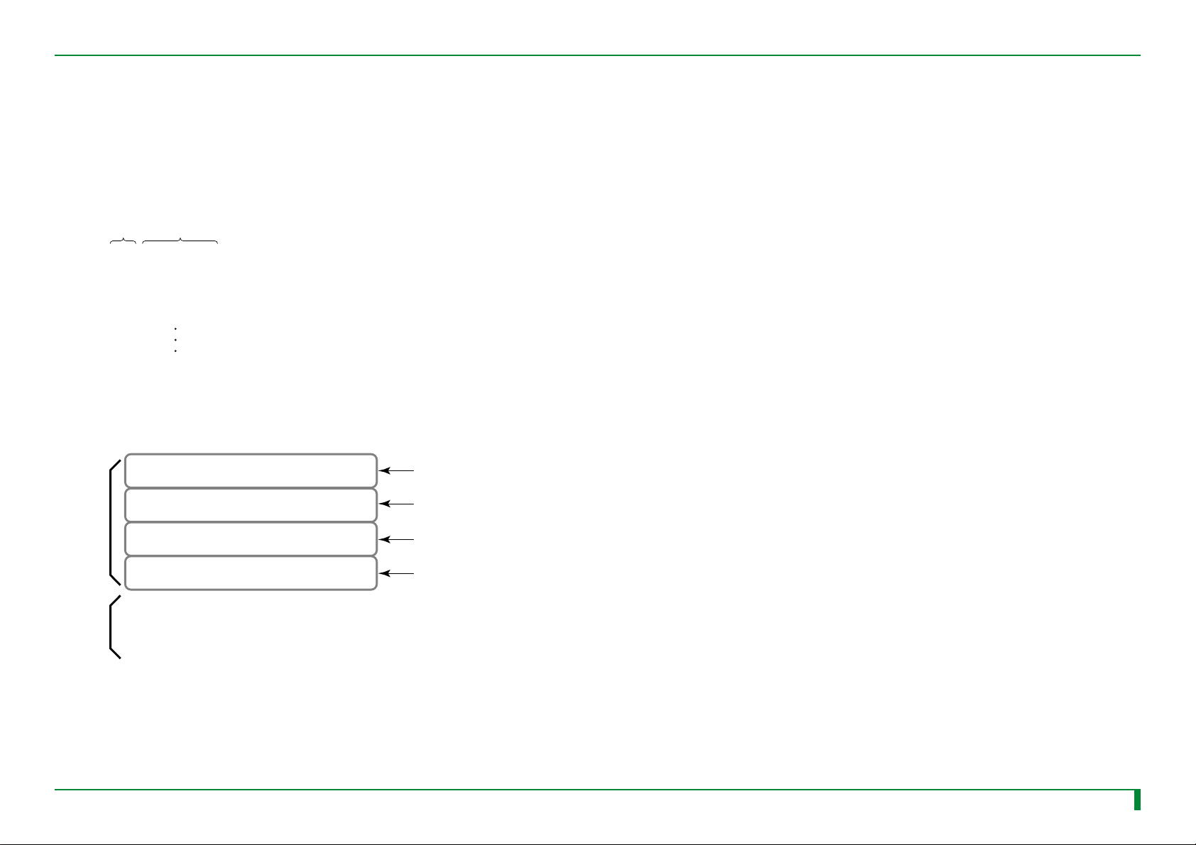
MT1 - 1
Code
Analysis
flow
Detail
Code
Name
Error code
Significance/Occurrence Condition Probable Cause/Remedy
Error name
Reference destination,
such as analysis flow,
check flow, etc.
Summary of the error Presumable cause of
error and remedy
MT4-12
7.1
Reference page or reference section number
Reference page
<Error Code Analysis Flow>
MT - 1
P
MT4- 1
MT4-1
FR7H2731.EPS
Section number
Error Code Analysis Flow (Mechanism)
03A2, 13A1, 13A2, 23A1, 23A2
■ Error Occurrence Conditions
03A2 Cassette hold release error
13A1 Cassette setting error 1
During routine/initialization/error handling (cassette hold check), the cassette
hold solenoid (SOLK1) is turned OFF, but the cassette hold sensor (SK3) does
not transition from Open to Close within 0.5 sec (TK14), and retry operation is
performed six times or more (NK12).
13A2 Cassette hold release error
During routine/initialization/error handling (cassette hold release check), the
cassette hold solenoid (SOLK1) is turned ON, but the cassette hold sensor
(SK3) does not transition from Close to Open within 0.5 sec (TK14), and retry
operation is performed six times or more (NK11).
23A1 Cassette hold failure retry
During routine/initialization/error handling (cassette hold check), the cassette
hold solenoid (SOLK1) is turned OFF to hold the cassette, but the cassette hold
sensor (SK3) does not transition from Open to Close within 0.5 sec (TK14).
23A2 Cassette hold release failure retry
During routine/initialization/error handling (cassette hold release check 2), the
cassette hold solenoid (SOLK1) is turned ON to release the cassette hold, but the
cassette hold sensor (SK3) does not transition from Close to Open within 0.5 sec
(TK14), and retry operation is performed.
■ I/O Locations
Cassette
Cassette set unit
■ Preparations
1. Turn OFF and uncover the machine.
2. Check for dirt and other foreign matter (lead character marking chips, etc.)
inside the machine. Any foreign matter must be removed.
■ Analysis Flow
Note the error log with
the M-Utility.
Is the sensor (SK3) normal?
Replace the components in the order indicated below:
1. SNS08C board
2. DRV08A board
3. CPU90E board
4. MTH08C board
5.SK3
6.SOLK1
Replace the sensor (SK3).
Is the solenoid (SOLK1)
normal?
Does the error recur?
“7.3 Checking the SK3”
“1.2 How to View the Error Log”
“7.31 Checking the SOLK1”
Replace the solenoid (SOLK1).
“15. Removing and Installing the PC Boards” in the “Checks,
Replacement, and Adjustment of Parts” volume
“4.7 Cassette Hold Sensor (SK3)” in the “Checks, Replacement,
and Adjustment of Parts” volume
“4.6 Cassette Hold Solenoid (SOLK1)” in the “Checks,
Replacement, and Adjustment of Parts” volume
During routine/initialization/error handling (cassette hold release check), the
cassette hold solenoid (SOLK1) is turned ON, but the cassette hold sensor (SK3)
does not transition from Close to Open within 0.5 sec (TK14), and retry operation
is performed six times or more (NK11).
1. Overview of Troubleshooting
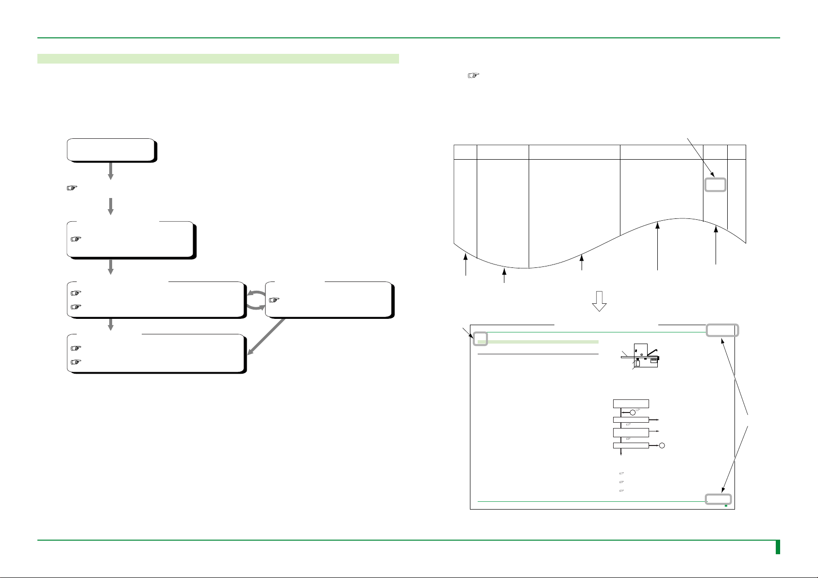
1.1 Flow of Troubleshooting
■ Overall Flow
When a trouble occurs, refer to the Troubleshooting Volume along the flow shown below to take
remedial action, such as parts replacement, as needed.
Trouble occurred
“9. Priority Checks to Be Conducted upon Trouble Occurrence”
009-058-03
08.30.2002 FM3476
<Error code is displayed>
“2. Error Code Table”
<Error Code Analysis Flow>
“4. Error Code Analysis Flow (Mechanism)”
“5. Error Code Analysis Flow (Scanner)”
<Remedial Action>
“Checks, Replacement, and Adjustment of Parts Volume”
“Service Parts List Volume”
<Check Flow>
“7. Check Flow”
FR7H2730.EPS
CR-IR347
■ How to Use the Analysis Flow
(1) Check the error code.
“1.2 How to Understand Error Log”
(2) Refer to the Error Code Table.
If any reference page is found in the “Error Code Analysis Flow” column of the Error Code
Table, proceed to its relevant error code analysis flow.
4.
009-058-00
10.20.2000 FM2731
Service Manual
Service Manual
SK3
SOLK1
FR7H2101.EPS
1
N
Y
N
Y
N
Y
1
FR7H2201.E
MT - 1CR-IR347
MT1 - 1
Page 8
MT1 - 2
a
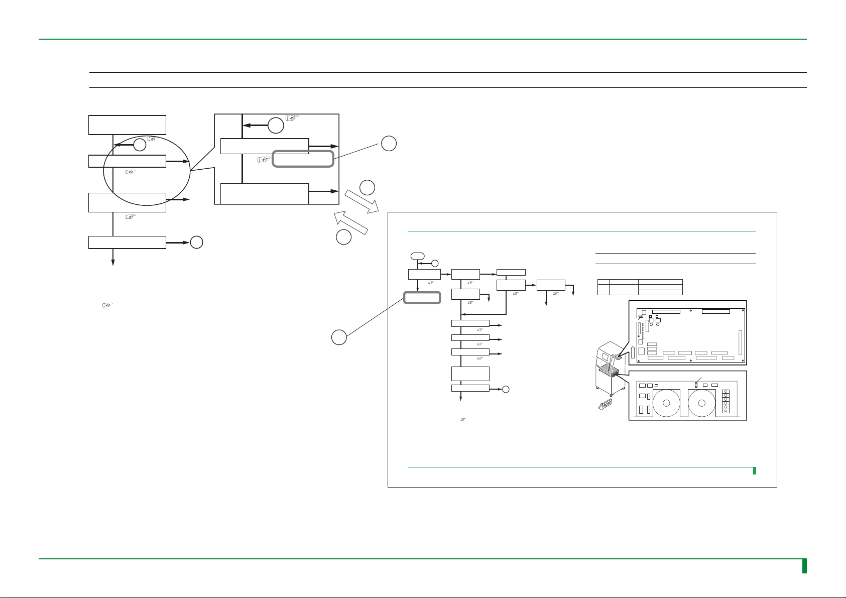
(3) Troubleshoot according to the analysis flow.
◆
NOTE
◆
When troubleshooting, refer to the Check Flow that describes the checking procedures for troubleshooting individual I/O parts, as well as “Check, Replacement, and Adjustment of Parts” volume.
<Error Code Analysis Flow>
“
Note the error log with
the M-Utility.
“
1.2 How to View the Error Log"
1
Is the sensor (SK1) normal? Replace the sensor (SK1).
“
7.1 Checking the SK1
Y
Is the solenoid (SOLK1)
normal?
“
Y
Does the error recur?
N
”
N
Replace the solenoid (SOLK1).
7.31 Checking the SOLK1
N
Is the sensor (SK1) normal?
Is the solenoid (SOLK1)
normal?
”
1
Y
Y
Replace the PC boards in the following order:
1. SNS08C board
2. DRV08A board
3. CPU90E board
4. MTH08C
board
“15. Removing and Installing the PC Boards”
in the “Checks, Replacement, and Adjustment of Parts” volume
Return to the Error Analysis Flow section
number page or indicated page.
1.2 How to
1
N
N
“
7.1 Checking the SK1
Proceed to the section number page.
A
”
A
<Check Flow>
MT 7- 2
[2] Checking with the M-Utility
[3]
Replace any
blown fuse.
FR7H2301.EPS
[6] [ENT] → [4] [ENT] → [3] [ENT]
◆
CHECKS
◆
1. Check that the sensor is “open” when its light path is not blocked.
2. Check that the sensor is
[3] Checking the voltage
Voltage
+5V
[4] Checking the mechanism
• SK1 replacement
“4.3 Cassette Ejection Sensor (SK1)” in the “Checks, Replacement, and Adjustment” volume
Standard value
4.75–5.25 V
SNS08C board
CN4
F
R
O
N
T
Power supply unit (JPS-6)
“
closed” when its light path is blocked.
Measurement point
SNS08C CN4 1-2
JPS-6 DCOUT2 1-2
1
TR7H2087.EPS
2
DC OUT2
2
1
FR7H2501.EPS
B
B
7.1 Checking the SK1
[1] Analysis Flow
START
A
Does the M-Utility
indicate that the sensor
operation is normal?
Y
Return to the error code
nalysis flow.
Are the SNS08C
N
board voltages
normal?
[2]
Is the SNS08C
board fuse normal?
Are the cables normal?
Is the mechanism normal?
Is the sensor normal?
Remove and reinstall the
CPU90E board and
connectors.
Does the error recur?
Replace the PC boards in the following order:
1. SNS08C board
2. CPU90E board
3. MTH08C board
Y
Y
Y
Y
Y
Y
N
Power OFF.
Are the power supply
[3]
N
[7]
Replace any
blown fuse.
N
[5], [6]
N
[4]
N
“Checks, Replacement, and Adjustment of Parts”
volume
N
“15. Removing and Installing the PC Boards” in the “Checks,
Replacement, and Adjustment of Parts” volume
NN
unit (JPS-6) voltages
normal?
Y
[3]
Replace any faulty cable.
Repair the mechanism.
Check the sensor.
A
Are the fuses for the
power supply unit
(JPS-6) normal?
Y
Replace the power
supply unit (JPS-6).
N
009-058-03
08.30.2002 FM3476
CR-IR347
009-058-00
10.20.2000 FM2731
Service Manual
CR-IR347
Service Manual
MT7 - 2
FR7H2732.EPS
MT1 - 2
Page 9
1.2 How to Understand Error Log
When an error code is displayed, check the error log.
■ How to Understand the Error Log List
When multiple errors occurred, the error at the beginning that occurred at the same time (with a
margin of about 2-4 minutes) is the most likely cause that is directly responsible for the trouble.
Check the error log to see which is the error at the beginning.
● Error log format
Error code Occurrence date
CODE DATE
03EF 2000.10.18 17:13
001000000000000001-0-0-011-0000101101.------
--.1.0.0.9.0.0.0.0000.0000.0000
23EB 2000.10.18 17:13
111000000000000001-0-0-011-0000101101.------
--.1.0.0.9.0.0.0.0000.0000.0000
● How to identify the error code at the beginning
In the error log example shown below, those denoted by “A” and “B” are errors that occurred at the
same time (with a margin of about 2 minutes), the error at the beginning for “A” is “23EB”.
Error codes displayed on the screen
CODE DATE
03EF 2000.10.18 17:13
001000000000000001-0-0-011-0000101101.------
--.1.0.0.9.0.0.0.0000.0000.0000
23EB 2000.10.18 17:13
111000000000000001-0-0-011-0000101101.------
A
B
--.1.0.0.9.0.0.0.0000.0000.0000
23EB 2000.10.18 17:13
111000000000000001-0-0-011-0000101101.------
--.1.0.0.9.0.0.0.0000.0000.0000
23EB 2000.10.18 17:13
111000000000000001-0-0-011-0000101101.------
--.1.0.0.9.8.8.8.0000.0000.0000
23E1 2000.10.18 16:55
1110000000000000000000001101000110010.------
--.1.0.0.0.0.0.0.0000.0000.0000
13A8 2000.10.18 16:55
11110000000000000000-0001110000110010.------
--.1.0.0.6.3.1.0.0000.0000.0000
03C2 2000.10.18 16:24
11100000000000000100-0001001000111010.000001
40.1.5.0.A.0.0.1.0000.0000.0000
13B8 2000.10.18 16:07
001000000000000001-0-0-011-1000101111.------
--.1.5.0.0.0.0.0.0000.0000.0000
0.END 1.NEXT 2.BEFORE (DEFAULT=1) :
FR7H2733.EPS
Error code that occurred last
Error code that
occurred third
Error code that
occurred second
Error code at the beginning:
It should be analyzed first.
FR7H2734.EPS
MT1 - 3
009-058-03
08.30.2002 FM3476
CR-IR347
Service Manual
MT1 - 3
Page 10
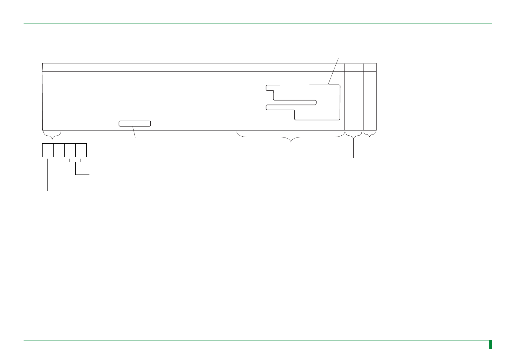
● Error code
An example of error code format is presented below.
Code Name
03BC
Side-positioning HP
operation error
[During initialization/normal processing]
Although the MN1 turned ON, the SN1 failed to close,
allowing the maximum retry count (NN51) to be exceeded.
<I/O name>
• MN1; Side-positioning motor
• SN1; Side-positioning mechanism home position sensor
<Reference>
MD-8.2.8/8.5.2
Significance/Occurrence Condition
Probable Cause/Remedy
• Perform the analysis flow for
Error 03BC (MT-4).
• Check the MN1 (MT-7.2/MU-4.6/SP-07).
• Check the SN1 (MT-7.10/MU-4.6/MC-8.4).
• Check the side-positioning conveyor
mechanism (MD-5.4/MC-8).
• Check the DRV08A board (MT-7.41/MC-15.11).
• Check the SNS08C board (MT-7.41/MC-15.11).
Indicates the reference volume
abbreviation and section number.
Analysis
flow
Detail
D-5MT4-13
MT1 - 4
Indicates the reference volume
abbreviation and section number.
XYZZ
Hexadecimal notation
00-FF: Reference number according to error classification
0-9, A-F: Error classification
0-3: Error level
X: Error level
• FATAL error: 0
Error where the normal processing cannot be resumed.
It is necessary to troubleshoot and take remedial action immediately.
• WARNING: 1, 2, 3
Errors where the processing may be resumed by performing retry
operation, etc.
This category includes an error that is merely logged as history information
and an error where the processing is resumed but its error code is displayed
on screen.
ZZ: Reference number
Managed according to the error classification
The checks to be performed are listed in random
order. Judge the target machine condition and
change the order of checks as needed to begin
by checking on the most probable error cause.
Y: Error classification
0: OS (operating system software), CPU, library
1: Overall control, information gathering function,
output destination control function
2: Panel control
3: Conveyor-related control
4: Image processing related (reading)
5: Scanner control
6: Undefined
7: IDT interface control
See “Section 2.3,
Format of Detail Information”.
Indicates the reference page for
“Analysis Flow” in this volume.
8: Printer interface control
9: Undefined
A: ID information setup function
B: Network output image processing
C: FINP control
D: DICOM control
E: Undefined
F: Other (software install, version update, etc.)
FR1H1316.EPS
009-058-03
08.30.2002 FM3476
CR-IR347
Service Manual
MT1 - 4
Page 11

2. Error Codes List
MT2-1
Code
0100
0101
0102
0110
Name Significance/Occurrence Condition
Board insertion position error
ID information control system
initialization error
Common data control system
initialization error
Image control system
initialization error
[During initialization]
The board insertion slot position was found to be abnormal when it was checked.
[During initialization/normal processing]
The ID information control system (IMM) was found to be abnormal.
[During initialization]
An error was detected in the common data control system (CDM).
[During initialization/normal processing]
An error was detected in the image control system (IDM).
Probable Cause/Remedy
• Check the board insertion location (MC-15).
• Check for improper board setup (MC-15).
• Check the board (MT-7.41).
• Check for an improper software update (MU-A1.2).
• Check the CPU90E board (MT-7.41/MC-15.3).
• Check the MTH08C/D board (MT-7.41/MC-15.1/MC-15.2).
• Check the HDD (MT-7.42/MC-11).
• Format the HDD and reinstall the software (MU-A1).
• Check the CPU90E board (MT-7.41/MC-15.3).
• Check the MTH08C/D board (MT-7.41/MC-15.1/MC-15.2).
• Check the HDD (MT-7.42/MC-11).
• Format the HDD and reinstall the software (MU-A1).
• Check the CPU90E board (MT-7.41/MC-15.3).
• Check the MTH08C/D board (MT-7.41/MC-15.1/MC-15.2).
• Check the HDD (MT-7.42/MC-11).
• Format the HDD and reinstall the software (MU-A1).
Analysis
flow
- A-8
-
-
-
Detail
F
F
F
009-058-03
08.30.2002 FM3476
CR-IR347 Service Manual [ 2. ] MT2-1
Page 12

Code
Name Significance/Occurrence Condition
Probable Cause/Remedy
MT2-2
Analysis
flow
Detail
0111
0112
0113
0120
HD image display area
initialization error
No effective option
Not enough common memory
File open error
[During initialization/normal processing]
An error was detected in the HD image display area.
[During initialization/normal processing]
An error was detected when shared memory allocation was attempted for option
configuration.
[During initialization]
It was detected that the capacity of the common memory is insufficient.
[During initialization]
An error was detected when an attempt was made to open a configuration file
(NETMASKS).
• Check the CPU90E board (MT-7.41/MC-15.3).
• Check the MTH08C/D board (MT-7.41/MC-15.1/MC-15.2).
• Check the HDD (MT-7.42/MC-11).
• Format the HDD and reinstall the software (MU-A1).
• Check the CPU90E board (MT-7.41/MC-15.3).
• Check the MTH08C/D board (MT-7.41/MC-15.1/MC-15.2).
• Check the MMA90A and MMB90A/DIM08A board
(MT-7.41/MC-15/IN-5.5).
• Check the HDD (MT-7.42/MC-11).
• Format the HDD and reinstall the software (MU-A1).
• Check the MTH08C/D board (MT-7.41/MC-15.1/MC-15.2).
• Check the MMA90A and MMB90A/DIM08A board
(MT-7.41/MC-15/IN-5.5).
• Check the CPU90E board (MT-7.41/MC-15.3).
• Check the MTH08C/D board (MT-7.41/MC-15.1/MC-15.2).
• Check the HDD (MT-7.42/MC-11).
• Format the HDD and reinstall the software (MU-A1).
-
-
- E-5
-
A-1
F
F
009-058-03
08.30.2002 FM3476
CR-IR347 Service Manual [ 2. ] MT2-2
Page 13

Code
Name Significance/Occurrence Condition
Probable Cause/Remedy
MT2-3
Analysis
flow
Detail
0121
0122
0123
0130
File read error
File close error
File format error
File open error
[During initialization]
An error was detected when an attempt was made to read a configuration file
(NETMASKS).
[During initialization]
An error was detected when an attempt was made to close a configuration file
(NETMASKS).
[During initialization]
An error was found in the format of a configuration file (NETMASKS).
[During initialization]
An error was detected when an attempt was made to open a configuration file
(HOSTS ADDRESS).
• Check the CPU90E board (MT-7.41/MC-15.3).
• Check the MTH08C/D board (MT-7.41/MC-15.1/MC-15.2).
• Check the HDD (MT-7.42/MC-11).
• Format the HDD and reinstall the software (MU-A1).
• Check the CPU90E board (MT-7.41/MC-15.3).
• Check the MTH08C/D board (MT-7.41/MC-15.1/MC-15.2).
• Check the HDD (MT-7.42/MC-11).
• Format the HDD and reinstall the software (MU-A1).
• Check the configuration settings (MU-4.2).
• Check the CPU90E board (MT-7.41/MC-15.3).
• Check the MTH08C/D board (MT-7.41/MC-15.1/MC-15.2).
• Check the HDD (MT-7.42/MC-11).
• Check the CPU90E board (MT-7.41/MC-15.3).
• Check the MTH08C/D board (MT-7.41/MC-15.1/MC-15.2).
• Check the HDD (MT-7.42/MC-11).
• Format the HDD and reinstall the software (MU-A1).
-
-
-
-
A-1
A-1
A-1
A-1
009-058-03
08.30.2002 FM3476
CR-IR347 Service Manual [ 2. ] MT2-3
Page 14

Code
Name Significance/Occurrence Condition
Probable Cause/Remedy
MT2-4
Analysis
flow
Detail
0131
0132
0133
0134
0140
File read error
File close error
File format error
File setting value error
Boot line-related error
[During initialization]
An error was detected when an attempt was made to read a configuration file
(HOSTS ADDRESS).
[During initialization]
An error was detected when an attempt was made to close a configuration file
(HOSTS ADDRESS).
[During initialization]
An error was found in the format of a configuration file (HOSTS ADDRESS).
[During initialization]
An error was found in the settings contained in a configuration file (HOSTS
ADDRESS).
[During initialization]
An error was detected in the backup memory data.
• Check the CPU90E board (MT-7.41/MC-15.3).
• Check the MTH08C/D board (MT-7.41/MC-15.1/MC-15.2).
• Check the HDD (MT-7.42/MC-11).
• Format the HDD and reinstall the software (MU-A1).
• Check the CPU90E board (MT-7.41/MC-15.3).
• Check the MTH08C/D board (MT-7.41/MC-15.1/MC-15.2).
• Check the HDD (MT-7.42/MC-11).
• Format the HDD and reinstall the software (MU-A1).
• Check the configuration settings (MU-4.2).
• Check the CPU90E board (MT-7.41/MC-15.3).
• Check the MTH08C/D board (MT-7.41/MC-15.1/MC-15.2).
• Check the HDD (MT-7.42/MC-11).
• Check the configuration settings (MU-4.2).
• Check the CPU90E board (MT-7.41/MC-15.3).
• Check the MTH08C/D board (MT-7.41/MC-15.1/MC-15.2).
• Check the HDD (MT-7.42/MC-11).
• Check the CPU90E board (MT-7.41/MC-15.3). -
-
-
-
-
A-1
A-1
A-1
A-1
F
009-058-03
08.30.2002 FM3476
CR-IR347 Service Manual [ 2. ] MT2-4
Page 15

Code
Name Significance/Occurrence Condition
Probable Cause/Remedy
MT2-5
Analysis
flow
Detail
0141
01A0
01A1
01A2
Routing information-related
error
ID information read error
ID information update error
Image data close error
[During initialization]
An error was found in the settings contained in a configuration file
(ROUTING/HOSTS ADDRESS).
[During initialization/normal processing]
An error was detected when an attempt was made to read ID information.
[During initialization/normal processing]
An error was detected when an attempt was made to update ID information.
[During initialization/normal processing]
An error was detected when an attempt was made to close an image data file.
• Check the configuration settings (MU-4.2).
• Check the CPU90E board (MT-7.41/MC-15.3).
• Check the MTH08C/D board (MT-7.41/MC-15.1/MC-15.2).
• Check the HDD (MT-7.42/MC-11).
• Check the CPU90E board (MT-7.41/MC-15.3).
• Check the MTH08C/D board (MT-7.41/MC-15.1/MC-15.2).
• Check the MMA90A and MMB90A/DIM08A board
(MT-7.41/MC-15/IN-5.5).
• Check the HDD (MT-7.42/MC-11).
• Check the CPU90E board (MT-7.41/MC-15.3).
• Check the MTH08C/D board (MT-7.41/MC-15.1/MC-15.2).
• Check the MMA90A and MMB90A/DIM08A board
(MT-7.41/MC-15/IN-5.5).
• Check the HDD (MT-7.42/MC-11).
• Check the CPU90E board (MT-7.41/MC-15.3).
• Check the MTH08C/D board (MT-7.41/MC-15.1/MC-15.2).
• Check the HDD (MT-7.42/MC-11).
• Format the HDD and reinstall the software (MU-A1).
-
-
-
-
F
D
D
D
009-058-03
08.30.2002 FM3476
CR-IR347 Service Manual [ 2. ] MT2-5
Page 16

Code
01A3
0200
Name Significance/Occurrence Condition
EQUIP file format error
Image data close error
[During initialization]
An error was found in the format contained in a configuration file (EQUIPMENT).
[During U-Utility mode]
An error was detected when an attempt was made to delete an image queued for
processing.
Probable Cause/Remedy
• Check the configuration settings (MU-4.2).
• Check the CPU90E board (MT-7.41/MC-15.3).
• Check the MTH08C/D board (MT-7.41/MC-15.1/MC-15.2).
• Check the HDD (MT-7.42/MC-11).
• Check the CPU90E board (MT-7.41/MC-15.3).
• Check the MTH08C/D board (MT-7.41/MC-15.1/MC-15.2).
• Check the MMA90A and MMB90A/DIM08A board
(MT-7.41/MC-15/IN-5.5).
• Check the HDD (MT-7.42/MC-11).
MT2-6
Analysis
flow
-
-
Detail
D
-
0301
0302
File open error
File format error
[During initialization]
An error was detected when an attempt was made to open a subsystem (IPH) file
on the HDD.
[During initialization]
An error was found in the data format of a subsystem (IPH) file on the HDD.
• Check the CPU90E board (MT-7.41/MC-15.3).
• Check the MTH08C/D board (MT-7.41/MC-15.1/MC-15.2).
• Check the HDD (MT-7.42/MC-11).
• Format the HDD and reinstall the software (MU-A1).
• Check the CPU90E board (MT-7.41/MC-15.3).
• Check the MTH08C/D board (MT-7.41/MC-15.1/MC-15.2).
• Check the HDD (MT-7.42/MC-11).
• Format the HDD and reinstall the software (MU-A1).
-
-
D-1
D-1
009-058-03
08.30.2002 FM3476
CR-IR347 Service Manual [ 2. ] MT2-6
Page 17
Code
Name Significance/Occurrence Condition
Probable Cause/Remedy
MT2-7
Analysis
flow
Detail
0303
0304
0311
0312
0322
File setting value error
File read error
FPMC device error
Motor stop time-out
SNS device error
[During initialization]
An error was found in the setting data contained in a subsystem (IPH) file on the
HDD.
[During initialization]
An error was detected when an attempt was made to read a subsystem (IPH) file
on the HDD.
[During initialization]
An error was detected when an attempt was made to initialize the FPMC device
for the CPU memory (CPU90E board).
[During initialization/normal processing]
Although a pulse motor drive request or stop request was issued, a timeout
occurred because the target pulse motor could not be driven or stopped.
[During initialization]
An error was detected when an attempt was made to initialize the SNS device.
• Check the CPU90E board (MT-7.41/MC-15.3).
• Check the MTH08C/D board (MT-7.41/MC-15.1/MC-15.2).
• Check the HDD (MT-7.42/MC-11).
• Format the HDD and reinstall the software (MU-A1).
• Check the CPU90E board (MT-7.41/MC-15.3).
• Check the MTH08C/D board (MT-7.41/MC-15.1/MC-15.2).
• Check the HDD (MT-7.42/MC-11).
• Format the HDD and reinstall the software (MU-A1).
• Check the CPU90E board (MT-7.41/MC-15.3). - D-3
• Check the CPU90E board (MT-7.41/MC-15.3).
• Check the DRV08A board (MT-7.41/MC-15.11).
• Check the SNS08C board (MT-7.41/MC-15.11).
• Check the CPU90E board (MT-7.41/MC-15.3). -
-
-
- D-3
D-1
D-1
D-3
009-058-03
08.30.2002 FM3476
CR-IR347 Service Manual [ 2. ] MT2-7
Page 18

Code
03A2
Name Significance/Occurrence Condition
Cassette hold release error
[During initialization/normal processing/M-Utility mode/abnormality processing]
Although the SOLK1 turned ON, the SK3 failed to open, allowing the maximum
retry count (NK11) to be exceeded.
<I/O name>
• SOLK1; Cassette hold solenoid
• SK3; Cassette hold sensor
<Reference>
MD-8.6.2
Probable Cause/Remedy
• Perform the analysis flow for Error 03A2 (MT-4).
• Check the SOLK1 (MT-7.31/MU-4.6/MC-4.6).
• Check the SK3 (MT-7.3/MU-4.6/MC-4.7).
• Check the cassette set unit mechanism (MD-5.1/MC-4).
• Check the cassette.
• Check the DRV08A board (MT-7.41/MC-15.11).
• Check the SNS08C board (MT-7.41/MC-15.11).
MT2-8
Analysis
flow
MT4-1
Detail
D-5
03A8
03B0
Nonstandard initialization IP
size
IP feed/load conveyor
remaining IP discharge
impossible
[During initialization]
When the IP size was checked, the CLOSE time combination of the SM1 did not
agree with the IP size data stored in the machine.
<I/O name>
• SM1; Before-BCR IP sensor
<Reference>
MD-8.2.4 (IP identification condition table)
[During initialization]
When the machine was searched for IPs, the remaining IP process could not be
performed for one of the following reasons:
• Cassette detection was not achievable.
• The CMOS information was abnormal.
<Reference>
MD-8.5.8
• Check the IP and cassette.
• Check the MM1 (MT-7.20/MU-4.6/MC-6.14).
• Check the MN3 (MT-7.23/MU-4.6/SP-07).
• Check the SM1 (MT-7.9/MU-4.6/SP-05).
• Check the cassette set unit mechanism (MD-5.1/MC-4).
• Check the IP removal unit mechanism (MD-5.2/MC-5).
• Check the side-positioning conveyor mechanism
(MD-5.4/MC-8).
• Check the DRV08A board (MT-7.41/MC-15.11).
• Check the SNS08C board (MT-7.41/MC-15.11).
• Check the SK1 (MT-7.1/MU-4.6/MC-4.3).
• Check the SK2 (MT-7.2/MU-4.6/MC-4.9).
• Clear the backup memory and then perform a reset (IN-17).
• Check the cassette.
• Check the cassette set unit mechanism (MD-5.1/MC-4).
-
- D-5
D-5
009-058-03
08.30.2002 FM3476
CR-IR347 Service Manual [ 2. ] MT2-8
Page 19

Code
03B1
Name Significance/Occurrence Condition
IP feed conveyance error
[During initialization/normal processing]
Although the MN3/MM1/ML2 was turned ON, the SM1 did not close and a timeout
occurred.
<I/O name>
• MN3/MM1/ML2; IP transport motor
• SM1; Before-BCR IP sensor
<Reference>
MD-8.2.3
Probable Cause/Remedy
• Perform the analysis flow for Error 03B1 (MT-4).
• Check the MN3 (MT-7.23/MU-4.6/SP-07).
• Check the MM1 (MT-7.20/MU-4.6/MC-6.14).
• Check the ML2 (MT-7.19/MU-4.6/MC-5.22).
• Check the SM1 (MT-7.9/MU-4.6/SP-05).
• Check the IP removal unit mechanism (MD-5.2/MC-5).
• Check the side-positioning conveyor mechanism
(MD-5.4/MC-8).
• Check the fuse (F11) for the power supply (JPS-6)
(MD-1.6/MT-7.40/MC-13.2).
• Check the DRV08A board (MT-7.41/MC-15.11).
• Check the SNS08C board (MT-7.41/MC-15.11).
MT2-9
Analysis
flow
MT4-8
Detail
D-5
03B2
IP load conveyance error
[During initialization/normal processing]
Although the ML2/MM1/MN3 turned ON, a timeout occurred because the SK2
failed to close.
<I/O name>
• ML2/MM1/MN3; IP transport motor
• SK2; Cassette IN sensor
<Reference>
MD-8.2.16/8.2.17/8.4.1
• Perform the analysis flow for Error 03B2 (MT-4).
• Check the ML2 (MT-7.19/MU-4.6/MC-5.22).
• Check the MM1 (MT-7.20/MU-4.6/MC-6.14).
• Check the MN3 (MT-7.23/MU-4.6/SP-07).
• Check the SK2 (MT-7.2/MU-4.6/MC-4.9).
• Check the IP removal unit mechanism (MD-5.2/MC-5).
• Check the DRV08A board (MT-7.41/MC-15.11).
• Check the SNS08C board (MT-7.41/MC-15.11).
MT4-9
D-5
009-058-03
08.30.2002 FM3476
CR-IR347 Service Manual [ 2. ] MT2-9
Page 20

Code
03B3
Name Significance/Occurrence Condition
Side-positioning conveyor
entrance conveyance error
[During initialization/normal processing]
Although the MN3 turned ON, the SN3 did not close after the SM1 closing.
Therefore, a retry operation was performed.
<I/O name>
• MN3; IP transport motor
• SM1; Before-BCR IP sensor
• SN3; Side-positioning IP sensor
<Reference>
MD-8.2.6
Probable Cause/Remedy
• Perform the analysis flow for Error 03B3 (MT-4).
• Check the MN3 (MT-7.23/MU-4.6/SP-07).
• Check the SN3 (MT-7.12/MU-4.6/MC-8.8).
• Check the side-positioning conveyor mechanism
(MD-5.4/MC-8).
• Check the DRV08A board (MT-7.41/MC-15.11).
• Check the SNS08C board (MT-7.41/MC-15.11).
MT2-10
Analysis
flow
MT4-10
Detail
D-5
03B4
03B5
Restored IP load low-speed
conveyance error
Restored IP load high-speed
conveyance error
[During normal processing/abnormality processing]
Although the MN3/MM1/ML2 turned ON, the SL2 did not open.
<I/O name>
• MN3/MM1/ML2; IP transport motor
• SL2; Cassette inlet IP sensor
<Reference>
MD-8.3.1
[During normal processing/abnormality processing]
Although the MN3/MM1/ML2 turned ON, the SL2 did not close.
<I/O name>
• MN3/MM1/ML2; IP transport motor
• SL2; Cassette inlet IP sensor
<Reference>
MD-8.3.1
• Perform the analysis flow for Error 03B4 (MT-4).
• Check the MN3 (MT-7.23/MU-4.6/SP-07).
• Check the MM1 (MT-7.20/MU-4.6/MC-6.14).
• Check the ML2 (MT-7.19/MU-4.6/MC-5.22).
• Check the SL2 (MT-7.6/MU-4.6/SP-04).
• Check the IP removal unit mechanism (MD-5.2/MC-5).
• Check the DRV08A board (MT-7.41/MC-15.11).
• Check the SNS08C board (MT-7.41/MC-15.11).
• Perform the analysis flow for Error 03B5 (MT-4).
• Check the MN3 (MT-7.23/MU-4.6/SP-07).
• Check the MM1 (MT-7.20/MU-4.6/MC-6.14).
• Check the ML2 (MT-7.19/MU-4.6/MC-5.22).
• Check the SL2 (MT-7.6/MU-4.6/SP-04).
• Check the IP removal unit mechanism (MD-5.2/MC-5).
• Check the DRV08A board (MT-7.41/MC-15.11).
• Check the SNS08C board (MT-7.41/MC-15.11).
MT4-11 D-5
MT4-11 D-5
009-058-03
08.30.2002 FM3476
CR-IR347 Service Manual [ 2. ] MT2-10
Page 21

Code
Name Significance/Occurrence Condition
Probable Cause/Remedy
MT2-11
Analysis
flow
Detail
03B6
IP feed/load conveyor
remaining IP discharge error
[During initialization]
• Although the ML2/MM1/MN3 turned ON, the SL2 did not open.
• Although the ML2/MM1/MN3 turned ON, the SM1 did not open.
• Although the ML2 turned ON, the SL2 did not open.
• An error was found in the CMOS information.
<I/O name>
• ML2/MM1/MN3; IP transport motor
• SL2; Cassette inlet IP sensor
• SM1; Before-BCR IP sensor
<Reference>
MD-8.5.6/8.5.8/8.5.10
• Perform the analysis flow for Error 03B6 (MT-4).
• Check the ML2 (MT-7.19/MU-4.6/MC-5.22).
• Check the MM1 (MT-7.20/MU-4.6/MC-6.14).
• Check the MN3 (MT-7.23/MU-4.6/SP-07).
• Check the SL2 (MT-7.6/MU-4.6/SP-04).
• Check the SM1 (MT-7.9/MU-4.6/SP-05).
• Check the IP removal unit mechanism (MD-5.2/MC-5).
• Check the side-positioning conveyor mechanism
(MD-5.4/MC-8).
• Clear the backup memory and then perform a reset (IN-17).
• Check the MTH08C/D board (MT-7.41/MC-15.1/MC-15.2).
• Check the DRV08A board (MT-7.41/MC-15.11).
• Check the SNS08C board (MT-7.41/MC-15.11).
MT4-11 D-5
009-058-03
08.30.2002 FM3476
CR-IR347 Service Manual [ 2. ] MT2-11
Page 22

Code
03B7
Name Significance/Occurrence Condition
Side-positioning conveyor
remaining IP discharge error
[During initialization]
• Although the MN3 and MZ1 turned ON to reverse for the purpose of moving
the remaining IP in the before-reading conveyor, the SM1 did not close. Or
when the MN3 turned ON for feed conveyance after the SM1 close, the SN3
did not close.
• Although the MN3 turned ON for feed conveyance to search for a remaining
IP in the before-reading conveyor, the SN3 did not close.
[During initialization/normal processing]
Although the ML2/MM1/MN3 turned ON for feed conveyance to move the
remaining IP in the before-reading conveyor, the SM1 did not open.
Or when the MN3 turned ON for feed conveyance after the SM1 close, the SN3
did not close.
<I/O name>
• ML2/MM1/MN3; IP transport motor
• MZ1; Subscanning motor
• SM1; Before-BCR IP sensor
• SN3; Side-positioning IP sensor
<Reference>
MD-8.5.6
Probable Cause/Remedy
• Perform the analysis flow for Error 03B7 (MT-4).
• Check the MN3 (MT-7.23/MU-4.6/SP-07).
• Check the MZ1 (MT-7.25/MC-10.6).
• Check the SN3 (MT-7.12/MU-4.6/MC-8.8).
• Check the SM1 (MT-7.9/MU-4.6/SP-05).
• Check the SZ1 (MT-7.14/MC-10.11).
• Check the side-positioning conveyor mechanism
(MD-5.4/MC-8).
• Check the subscanning unit mechanism (MD-5.5/MC-10).
• Clear the backup memory and then perform a reset (IN-17).
• Check the MTH08C/D board (MT-7.41/MC-15.1/MC-15.2).
• Check the DRV08A board (MT-7.41/MC-15.11).
• Check the SNS08C board (MT-7.41/MC-15.11).
MT2-12
Analysis
flow
MT4-12 D-5
Detail
03B8
009-058-03
08.30.2002 FM3476
IP position information error
[During initialization]
The machine's CMOS information (IP found) did not agree with the remaining IP
search result (no IP).
<Reference>
MD-8.5.8/8.5.10
CR-IR347 Service Manual [ 2. ] MT2-12
• Clear the backup memory and then perform a reset (IN-17).
• Turn the power OFF and then back ON to achieve
automatic discharge, clear the backup memory,
and then perform a reset (IN-17).
• Check the MTH08C/D board (MT-7.41/MC-15.1/MC-15.2).
-
D-5
Page 23

Code
03BC
Name Significance/Occurrence Condition
Side-positioning HP
operation error
[During initialization/normal processing]
Although the MN1 turned ON, the SN1 failed to close, allowing the maximum retry
count (NN51) to be exceeded.
<I/O name>
• MN1; Side-positioning motor
• SN1; Side-positioning mechanism home position sensor
<Reference>
MD-8.2.8/8.5.2
Probable Cause/Remedy
• Perform the analysis flow for Error 03BC (MT-4).
• Check the MN1 (MT-7.21/MU-4.6/SP-07).
• Check the SN1 (MT-7.10/MU-4.6/MC-8.4).
• Check the side-positioning conveyor mechanism
(MD-5.4/MC-8).
• Check the DRV08A board (MT-7.41/MC-15.11).
• Check the SNS08C board (MT-7.41/MC-15.11).
MT2-13
Analysis
flow
MT4-13
Detail
D-5
03BF
03C0
Side-positioning grip
operation error
IP pre-reading conveyance
error
[During initialization/normal processing]
Although the MN2 turned ON, the SN2 failed to close, allowing the maximum retry
count (NN61) to be exceeded.
<I/O name>
• MN2; Grip release motor
• SN2; Grip release home position sensor
<Reference>
MD-8.2.11/8.5.1
[During initialization/normal processing]
Although the MN3 turned ON, the SZ1 closed before the SN1 closing.
<I/O name>
• MN3; IP transport motor
• SN1; Side-positioning mechanism home position sensor
• SZ1; IP leading edge sensor
• Perform the analysis flow for Error 03BF (MT-4).
• Check the MN2 (MT-7.22/MU-4.6/MC-8.2).
• Check the SN2 (MT-7.11/MU-4.6/MC-8.5).
• Check the side-positioning conveyor mechanism
(MD-5.4/MC-8).
• Check the power supply (JPS-6) (MT-7.40/MC-13.1).
• Check the fuse (F9/F12) for the power supply (JPS-6)
(MD-1.6/MT-7.40/MC-13.2).
• Clear the backup memory and then perform a reset (IN-17).
• Check the MTH08C/D board (MT-7.41/MC-15.1/MC-15.2).
• Check the DRV08A board (MT-7.41/MC-15.11).
• Check the SNS08C board (MT-7.41/MC-15.11).
• Perform the analysis flow for Error 03C0 (MT-4).
• Check the MN3 (MT-7.23/MU-4.6/SP-07).
• Check the SN1 (MT-7.10/MU-4.6/MC-8.4).
• Check the SZ1 (MT-7.14/MC-10.11).
• Check the side-positioning conveyor mechanism
(MD-5.4/MC-8).
• Check the subscanning unit mechanism (MD-5.5/MC-10).
• Check the IP.
• Check the DRV08A board (MT-7.41/MC-15.11).
• Check the SNS08C board (MT-7.41/MC-15.11).
MT4-14
MT4-16
D-5
D-5
009-058-03
08.30.2002 FM3476
CR-IR347 Service Manual [ 2. ] MT2-13
Page 24

Code
03C1
Name Significance/Occurrence Condition
IP reading conveyance error
[During normal processing]
Although the MZ1 turned ON, the SN3 did not open.
[During secondary erasure]
Although the MZ1 and MN3 turned ON, the SN3 did not open.
<I/O name>
• MZ1; Subscanning motor
• SN3; Side-positioning IP sensor
• MN3; IP transport motor
<Reference>
MD-8.2.11
Probable Cause/Remedy
• Perform the analysis flow for Error 03C1 (MT-4).
• Check the MZ1 (MT-7.25/MC-10.6).
• Check the MN3 (MT-7.23/MU-4.6/SP-07).
• Check the SN3 (MT-7.12/MU-4.6/MC-8.8).
• Check the subscanning unit mechanism (MD-5.5/MC-10).
• Check the power supply (JPS-6) (MT-7.40/MC-13.1).
• Check the fuse (F3/F4) for the power supply (JPS-6)
(MD-1.6/MT-7.40/MC-13.2).
• Check the DRV08A board (MT-7.41/MC-15.11).
• Check the SNS08C board (MT-7.41/MC-15.11).
MT2-14
Analysis
flow
MT4-15 D-5
Detail
03C2
Reading IP leading edge
detection error
[During normal processing]
Although the MZ1 turned ON, the SZ1 did not close.
<I/O name>
• MZ1; Subscanning motor
• SZ1; IP leading edge sensor
<Reference>
MD-8.2.11
• Perform the analysis flow for Error 03C2 (MT-4).
• Check the IP.
• Check the MZ1 (MT-7.25/MC-10.6).
• Check the SZ1 (MT-7.14/MC-10.11).
• Check the subscanning unit mechanism (MD-5.5/MC-10).
• Check the power supply (JPS-6) (MT-7.40/MC-13.1).
• Check the MTH08C/D board (MT-7.41/MC-15.1/MC-15.2).
• Check the SCN08D board (MT-7.41/MC-10.19).
• Check the DRV08A board (MT-7.41/MC-15.11).
• Check the SNS08C board (MT-7.41/MC-15.11).
MT4-16
D-5
009-058-03
08.30.2002 FM3476
CR-IR347 Service Manual [ 2. ] MT2-14
Page 25

Code
Name Significance/Occurrence Condition
Probable Cause/Remedy
MT2-15
Analysis
flow
Detail
03C6
03C7
03C8
Drive shaft grip error
Driven shaft grip release
error
Drive shaft grip release error
[During initialization/normal processing]
Although the MZ2 turned ON, the SZ2 did not open.
<I/O name>
• MZ2; Driving-shaft grip motor
• SZ2; Driving-side grip release home position sensor
<Reference>
MD-8.2.11/8.5.4/8.5.11
[During initialization/normal processing]
Although the MZ3 turned ON, the SZ3 did not open.
<I/O name>
• MZ3; Driven-shaft grip motor
• SZ3; Driven-side grip release home position sensor
<Reference>
MD-8.2.10/8.2.11/8.5.4/8.5.11
[During initialization/normal processing]
Although the MZ2 turned ON, the SZ2 did not close.
<I/O name>
• MZ2; Driving shaft grip motor
• SZ2; Driving-side grip release home position sensor
<Reference>
MD-8.2.14/8.5.11
• Perform the analysis flow for Error 03C6/03C8/03CA (MT-4).
• Check the MZ2 (MT-7.26/MU-4.6/MC-10.15).
• Check the SZ2 (MT-7.15/MU-4.6/MC-10.1).
• Check the subscanning unit mechanism (MD-5.5/MC-10).
• Check the fuse (F2) for the power supply (JPS-6)
(MD-1.6/MT-7.40/MC-13.2).
• Check the DRV08A board (MT-7.41/MC-15.11).
• Check the SNS08C board (MT-7.41/MC-15.11).
• Perform the analysis flow for Error 03C7/03C9/03CB (MT-4).
• Check the MZ3 (MT-7.27/MU-4.6/MC-10.16).
• Check the SZ3 (MT-7.16/MU-4.6/MC-10.17).
• Check the subscanning unit mechanism (MD-5.5/MC-10).
• Check the DRV08A board (MT-7.41/MC-15.11).
• Check the SNS08C board (MT-7.41/MC-15.11).
• Perform the analysis flow for Error 03C6/03C8/03CA (MT-4).
• Check the MZ2 (MT-7.26/MU-4.6/MC-10.15).
• Check the SZ2 (MC-7.15/MU-4.6/MC-10.1).
• Check the subscanning unit mechanism (MD-5.5/MC-10).
• Check the fuse (F2) for the power supply (JPS-6)
(MD-1.6/MT-7.40/MC-13.2).
• Check the DRV08A board (MT-7.41/MC-15.11).
• Check the SNS08C board (MT-7.41/MC-15.11).
MT4-17 D-5
MT4-18 D-5
MT4-17 D-5
009-058-03
08.30.2002 FM3476
CR-IR347 Service Manual [ 2. ] MT2-15
Page 26

Code
Name Significance/Occurrence Condition
Probable Cause/Remedy
MT2-16
Analysis
flow
Detail
03C9
03CA
03CB
Driven shaft grip error
Drive shaft grip
self-diagnosis error
Driven shaft grip release
self-diagnosis error
[During initialization/normal processing]
Although the MZ3 turned ON, the SZ3 failed to close.
<I/O name>
• MZ3; Driven-shaft grip motor
• SZ3; Driven-side grip release home position sensor
<Reference>
MD-8.2.11/8.2.14/8.5.4/8.5.11
[During initialization]
Although the MZ2 turned ON, the SZ2 did not open.
<I/O name>
• MZ2; Driving-shaft grip motor
• SZ2; Driving-side grip release home position sensor
<Reference>
MD-8.5.11
[During initialization]
Although the MZ3 turned ON, the SZ3 did not open.
<I/O name>
• MZ3; Driven-shaft grip motor
• SZ3; Driven-side grip release home position sensor
<Reference>
MD-8.5.11
• Perform the analysis flow for Error 03C7/03C9/03CB (MT-4).
• Check the MZ3 (MT-7.27/MU-4.6/MC-10.16).
• Check the SZ3 (MT-7.16/MU-4.6/MC-10.17).
• Check the subscanning unit mechanism (MD-5.5/MC-10).
• Check the DRV08A board (MT-7.41/MC-15.11).
• Check the SNS08C board (MT-7.41/MC-15.11).
• Clear the backup memory and then perform a reset (IN-17).
• Perform the analysis flow for Error 03C6/03C8/03CA (MT-4).
• Check the MZ2 (MT-7.26/MU-4.6/MC-10.15).
• Check the SZ2 (MT-7.15/MU-4.6/MC-10.1).
• Check the subscanning unit mechanism (MD-5.5/MC-10).
• Check the fuse (F2) for the power supply (JPS-6)
(MD-1.6/MT-7.40/MC-13.2).
• Check the DRV08A board (MT-7.41/MC-15.11).
• Check the SNS08C board (MT-7.41/MC-15.11).
• Perform the analysis flow for Error 03C7/03C9/03CB (MT-4).
• Check the MZ3 (MT-7.27/MU-4.6/MC-10.16).
• Check the SZ3 (MT-7.16/MU-4.6/MC-10.17).
• Check the subscanning unit mechanism (MD-5.5/MC-10).
• Check the DRV08A board (MT-7.41/MC-15.11).
• Check the SNS08C board (MT-7.41/MC-15.11).
MT4-18 D-5
MT4-17 D-5
MT4-18 D-5
009-058-03
08.30.2002 FM3476
CR-IR347 Service Manual [ 2. ] MT2-16
Page 27

Code
Name Significance/Occurrence Condition
Probable Cause/Remedy
MT2-17
Analysis
flow
Detail
03CC
03CD
03D3
Mirror operation error
Conveyance error
(side-positioning return
conveyance)
Pre-erasure conveyance
error
[During normal processing]
The MZ4 turned ON, but the SZ4 did not open.
<I/O name>
• MZ4; Mirror drive motor
• SZ4; Mirror home position sensor
<Reference>
MD-8.5.13
[During normal processing]
The MZ1/MN3 turned ON, but the SN3 did not close.
<I/O name>
• MZ1; Subscanning motor
• MN3; IP transport motor
• SN3; Side-positioning IP sensor
<Reference>
MD-8.2.6
[During normal processing]
Although the MM1/MN3 turned ON, the SM1 failed to close. Therefore, a retry
operation was performed.
<I/O name>
• MM1/MN3; IP transport motor
• SM1; Before-BCR IP sensor
<Reference>
MD-8.2.14
• Perform the analysis flow for Error 03CC (MT-4).
• Check the light-collecting mirror arm mechanism.
• Check the MZ4 (MT-7.28/MU-4.6/MC-10.14).
• Check the SZ3 (MT-7.16/MU-4.6/MC-10.17).
• Check the subscanning unit mechanism (MD-5.5/MC-10).
• Check the DRV08A board (MT-7.41/MC-15.11).
• Check the SNS08C board (MT-7.41/MC-15.11).
• Perform the analysis flow for Error 03CD (MT-4).
• Check the MZ4 (MT-7.28/MU-4.6/MC-10.14).
• Check the SZ3 (MT-7.16/MU-4.6/MC-10.17).
• Check the subscanning unit mechanism (MD-5.5/MC-10).
• Check the DRV08A board (MT-7.41/MC-15.11).
• Check the SNS08C board (MT-7.41/MC-15.11).
• Perform the analysis flow for Error 03D3 (MT-4).
• Check the MM1 (MT-7.20/MU-4.6/MC-12.7).
• Check the MN3 (MT-7.23/MU-4.6/MC-8.2).
• Check the SM1 (MT-7.9/MU-4.6/SP-05).
• Check the side-positioning conveyor mechanism
(MD-5.4/MC-8).
• Check the erasure conveyor mechanism (MD-5.3/MC-6).
• Check the DRV08A board (MT-7.41/MC-15.11).
• Check the SNS08C board (MT-7.41/MC-15.11).
MT4-19 D-5
MT4-20 D-5
MT4-22
D-5
009-058-03
08.30.2002 FM3476
CR-IR347 Service Manual [ 2. ] MT2-17
Page 28

Code
Name Significance/Occurrence Condition
Probable Cause/Remedy
MT2-18
Analysis
flow
Detail
03D5
03E8
03EE
Erasure conveyance error
Suction cup moving error
Cleaning guide return
operation error
[During normal processing]
Although the MN3/MM1/ML2 turned ON, the SM1 failed to open.
<I/O name>
• MN3/MM1/ML2; IP transport motor
• SM1; Before-BCR IP sensor
<Reference>
MD-8.2.15
[During initialization/normal processing/M-Utility mode/abnormality processing]
Although the ML1 turned ON, the SL1 failed to close, allowing the maximum retry
count (NL51) to be exceeded.
<I/O name>
• ML1; Suction cup drive motor
• SL1; Suction cup home position sensor
<Reference>
MD-8.2.2/8.5.7
[During initialization/normal processing/M-Utility mode/abnormality processing]
Although the ML1 turned ON, the SL1 failed to close, allowing the maximum retry
count (NL51) to be exceeded.
<I/O name>
• ML1; Suction cup drive motor
• SL1; Suction cup home position sensor
<Reference>
MD-8.2.2/8.5.7
• Perform the analysis flow for Error 03D5 (MT-4).
• Check the MN3 (MT-7.23/MU-4.6/SP-07).
• Check the MM1 (MT-7.20/MU-4.6/MC-6.14).
• Check the ML2 (MT-7.19/MU-4.6/MC-5.22).
• Check the SM1 (MT-7.9/MU-4.6/SP-05).
• Check the erasure conveyor mechanism (MD-5.3/MC-6).
• Check the DRV08A board (MT-7.41/MC-15.11).
• Check the SNS08C board (MT-7.41/MC-15.11).
• Perform the analysis flow for Error 03E8 (MT-4).
• Check the ML1 (MT-7.18/MU-4.6/MC-5.17).
• Check the SL1 (MT-7.5/MU-4.6/MC-5.3).
• Check the IP removal unit mechanism (MD-5.2/MC-5).
• Check the DRV08A board (MT-7.41/MC-15.11).
• Check the SNS08C board (MT-7.41/MC-15.11).
• Perform the analysis flow for Error 03EE (MT-4).
• Check the SN4 (MT-7.13/MU-4.6/MC-8.9).
• Check the side-positioning conveyor mechanism
(MD-5.4/MC-8).
• Check the DRV08A board (MT-7.41/MC-15.11).
• Check the SNS08C board (MT-7.41/MC-15.11).
MT4-23 D-5
MT4-27
MT4-28
D-5
D-5
009-058-03
08.30.2002 FM3476
CR-IR347 Service Manual [ 2. ] MT2-18
Page 29

Code
03EF
0400
0401
0402
Name Significance/Occurrence Condition
Cleaning guide operation
error
File open error
File format error
File setting value error
[During normal processing]
The MN4 is turned ON, but the SN4 does not close, allowing the maximum retry
count (NL51) to be exceeded.
<I/O name>
• MN4; Cleaning guide drive motor
• SN4; Cleaning guide home position sensor
<Reference>
MD-8.2.7/8.5.5
[During initialization]
An error was detected when an attempt was made to open a subsystem file (IMG).
[During initialization]
An error was found in the format of a subsystem file (IMG).
[During initialization]
An error was found in the settings contained in a subsystem file (IMG).
Probable Cause/Remedy
• Perform the analysis flow for Error 03EF (MT-4).
• Check the MN4 (MT-7.24/MU-4.6/MC-8.6).
• Check the SN4 (MT-7.13/MU-4.6/MC-8.9).
• Check the side-positioning conveyor mechanism
(MD-5.4/MC-8).
• Check the DRV08A board (MT-7.41/MC-15.11).
• Check the SNS08C board (MT-7.41/MC-15.11).
• Check the CPU90E board (MT-7.41/MC-15.3).
• Check the MTH08C/D board (MT-7.41/MC-15.1/MC-15.2).
• Check the HDD (MT-7.42/MC-11).
• Format the HDD and reinstall the software (MU-A1).
• Check the CPU90E board (MT-7.41/MC-15.3).
• Check the MTH08C/D board (MT-7.41/MC-15.1/MC-15.2).
• Check the HDD (MT-7.42/MC-11).
• Format the HDD and reinstall the software (MU-A1).
• Check the CPU90E board (MT-7.41/MC-15.3).
• Check the MTH08C/D board (MT-7.41/MC-15.1/MC-15.2).
• Check the HDD (MT-7.42/MC-11).
• Format the HDD and reinstall the software (MU-A1).
MT2-19
Analysis
flow
MT4-28
-
-
-
Detail
D-5
E-1
E-1
E-1
009-058-03
08.30.2002 FM3476
CR-IR347 Service Manual [ 2. ] MT2-19
Page 30

Code
0403
Name Significance/Occurrence Condition
File read error
[During initialization]
An error was detected when an attempt was made to read a subsystem file (IMG).
Probable Cause/Remedy
• Check the CPU90E board (MT-7.41/MC-15.3).
• Check the MTH08C/D board (MT-7.41/MC-15.1/MC-15.2).
• Check the HDD (MT-7.42/MC-11).
• Format the HDD and reinstall the software (MU-A1).
MT2-20
Analysis
flow
-
Detail
E-1
0410
0411
0412
0413
DSP4 device initialization
error
DSP4 device open error
DSP4 micro program boot
error
DSP4 micro program load
error
[During initialization]
An error was detected when an attempt was made to initialize the DSP4 device
(IMG07B board).
[During initialization]
An error was detected when an attempt was made to open the DSP4 device
(IMG07B board).
[During initialization]
An error was detected when an attempt was made to boot a micro program for the
DSP4 device (IMG07B board) from the HDD.
[During initialization]
An error was detected when an attempt was made to load a micro program into
the DSP4 device (IMG07B board).
• Check the CPU90E board (MT-7.41/MC-15.3). - E-2
• Check the CPU90E board (MT-7.41/MC-15.3). - E-2
• Check the CPU90E board (MT-7.41/MC-15.3).
• Check the MTH08C/D board (MT-7.41/MC-15.1/MC-15.2).
• Check the IMG07B board (MT-7.41/MC-15.4).
• Check the HDD (MT-7.42/MC-11).
• Check the CPU90E board (MT-7.41/MC-15.3).
• Check the MTH08C/D board (MT-7.41/MC-15.1/MC-15.2).
• Check the IMG07B board (MT-7.41/MC-15.4).
• Check the HDD (MT-7.42/MC-11).
-
-
E-2
E-2
009-058-03
08.30.2002 FM3476
CR-IR347 Service Manual [ 2. ] MT2-20
Page 31

Code
Name Significance/Occurrence Condition
Probable Cause/Remedy
MT2-21
Analysis
flow
Detail
0414
0415
0420
0421
DSP4 checksum error
DSP4 self-diagnosis error
DSP4 memory write error
DSP4 memory read error
[During initialization]
An error was found in the checksum on the micro program for the DSP4 device
(IMG07B board).
[During initialization]
An error was detected in the micro program self-diagnosis on the DSP4 device
(IMG07B board).
[During initialization/normal processing]
An error was detected when an attempt was made to write into the DSP4 device
(IMG07B board).
[During normal processing]
An error was detected when an attempt was made to read the DSP4 device
(IMG07B board).
• Check the CPU90E board (MT-7.41/MC-15.3).
• Check the MTH08C/D board (MT-7.41/MC-15.1/MC-15.2).
• Check the IMG07B board (MT-7.41/MC-15.4).
• Check the CPU90E board (MT-7.41/MC-15.3).
• Check the MTH08C/D board (MT-7.41/MC-15.1/MC-15.2).
• Check the IMG07B board (MT-7.41/MC-15.4).
• Check the CPU90E board (MT-7.41/MC-15.3).
• Check the MTH08C/D board (MT-7.41/MC-15.1/MC-15.2).
• Check the IMG07B board (MT-7.41/MC-15.4).
• Check the CPU90E board (MT-7.41/MC-15.3).
• Check the MTH08C/D board (MT-7.41/MC-15.1/MC-15.2).
• Check the IMG07B board (MT-7.41/MC-15.4).
- E-2
- E-2
- E-2
- E-2
009-058-03
08.30.2002 FM3476
CR-IR347 Service Manual [ 2. ] MT2-21
Page 32

Code
0422
0423
Name Significance/Occurrence Condition
DSP4 image processing
error 1
DSP4 image processing
error 2
[During normal processing]
An image processing error was found in the DSP4 device (IMG07B board) when
image data was being read from the scanner.
[During normal processing]
An image processing error was found in the DSP4 device (IMG07B board) after an
image data read from the scanner.
Probable Cause/Remedy
• Check the CPU90E board (MT-7.41/MC-15.3).
• Check the MTH08C/D board (MT-7.41/MC-15.1/MC-15.2).
• Check the IMG07B board (MT-7.41/MC-15.4).
• Check the SCN08D board (MT-7.41/MC-10.19).
• Check the MMA90A and MMB90A/DIM08A board
(MT-7.41/MC-15/IN-5.5).
• Check the cable (MT-7/SP-12).
• Check the fuse (F3/F4) for the power supply (JPS-6)
(MD-1.6/MT-7.40/MC-13.2).
• Check the MZ1/MZ2/MZ3
(MU-4.6/MC-10.6/MC-10.15/MC-10.16).
• Check the MN1/MN2/MN3 (SP-07/MC-8.2).
MT2-22
Analysis
flow
-
-
Detail
E-2
E-2
0425
009-058-03
08.30.2002 FM3476
DSP1 device initialization
error
[During initialization]
An error was detected when an attempt was made to initialize the DSP1 device
(BSP08A board).
CR-IR347 Service Manual [ 2. ] MT2-22
• Check the CPU90E board (MT-7.41/MC-15.3).
• Check the BSP08A board (MT-7.41/MC-15.5).
- E-2
Page 33

Code
Name Significance/Occurrence Condition
Probable Cause/Remedy
MT2-23
Analysis
flow
Detail
0426
0427
0428
0429
0430
0435
DSP1 device open error
DSP1 micro program boot
error
DSP1 micro program load
error
DSP1 checksum error
DSP1 self-diagnosis error
DSP1 memory write error
[During initialization]
An error was detected when an attempt was made to open the DSP1 device
(BSP08A board).
[During initialization]
An error was detected when an attempt was made to boot a micro program for the
DSP1 device (BSP08A board) from the HDD.
[During initialization]
An error was detected when an attempt was made to load a micro program into
the DSP1 device (BSP08A board).
[During initialization]
An error was found in the checksum on the micro program for the DSP1 device
(BSP08A board).
[During initialization]
An error was detected in the micro program self-diagnosis on the DSP1 device
(BSP08A board).
[During initialization/normal processing]
An error was detected when an attempt was made to write into the DSP1 device
(BSP08A board).
• Check the CPU90E board (MT-7.41/MC-15.3).
• Check the BSP08A board (MT-7.41/MC-15.5).
• Check the CPU90E board (MT-7.41/MC-15.3).
• Check the MTH08C/D board (MT-7.41/MC-15.1/MC-15.2).
• Check the BSP08A board (MT-7.41/MC-15.5).
• Check the HDD (MT-7.42/MC-11).
• Check the CPU90E board (MT-7.41/MC-15.3).
• Check the MTH08C/D board (MT-7.41/MC-15.1/MC-15.2).
• Check the BSP08A board (MT-7.41/MC-15.5).
• Check the HDD (MT-7.42/MC-11).
• Check the CPU90E board (MT-7.41/MC-15.3).
• Check the MTH08C/D board (MT-7.41/MC-15.1/MC-15.2).
• Check the BSP08A board (MT-7.41/MC-15.5).
• Check the CPU90E board (MT-7.41/MC-15.3).
• Check the MTH08C/D board (MT-7.41/MC-15.1/MC-15.2).
• Check the BSP08A board (MT-7.41/MC-15.5).
• Check the CPU90E board (MT-7.41/MC-15.3).
• Check the MTH08C/D board (MT-7.41/MC-15.1/MC-15.2).
• Check the BSP08A board (MT-7.41/MC-15.5).
- E-2
-
-
- E-2
- E-2
- E-2
E-2
E-2
009-058-03
08.30.2002 FM3476
CR-IR347 Service Manual [ 2. ] MT2-23
Page 34

Code
Name Significance/Occurrence Condition
Probable Cause/Remedy
MT2-24
Analysis
flow
Detail
0436
0437
0440
0441
DSP1 memory read error
DSP1 image processing
error 1
DSP2 device initialization
error
DSP2 device open error
[During normal processing]
An error was detected when an attempt was made to read the DSP1 device
(BSP08A board).
[During normal processing]
An image processing error was found in the DSP1 device (BSP08A board) when
image data was being read from the scanner.
[During initialization]
An error was detected when an attempt was made to initialize the DSP2 device
(BSP08A board).
[During initialization]
An error was detected when an attempt was made to open the DSP2 device
(BSP08A board).
• Check the CPU90E board (MT-7.41/MC-15.3).
• Check the MTH08C/D board (MT-7.41/MC-15.1/MC-15.2).
• Check the BSP08A board (MT-7.41/MC-15.5).
• Check the CPU90E board (MT-7.41/MC-15.3).
• Check the MTH08C/D board (MT-7.41/MC-15.1/MC-15.2).
• Check the BSP08A board (MT-7.41/MC-15.5).
• Check the SCN08D board (MT-7.41/MC-10.19).
• Check the MMA90A and MMB90A/DIM08A board
(MT-7.41/MC-15/IN-5.5).
• Check the cable (MT-7/SP-12).
• Check the fuse (F3/F4) for the power supply (JPS-6)
(MD-1.6/MT-7.40/MC-13.2).
• Check the MZ1/MZ2/MZ3
(MU-4.6/MC-10.6/MC-10.15/MC-10.16).
• Check the MN1/MN2/MN3 (SP-07/MC-8.2).
• Check the CPU90E board (MT-7.41/MC-15.3).
• Check the BSP08A board (MT-7.41/MC-15.5).
• Check the CPU90E board (MT-7.41/MC-15.3).
• Check the BSP08A board (MT-7.41/MC-15.5).
- E-2
-
- E-2
- E-2
E-2
009-058-03
08.30.2002 FM3476
CR-IR347 Service Manual [ 2. ] MT2-24
Page 35

Code
Name Significance/Occurrence Condition
Probable Cause/Remedy
MT2-25
Analysis
flow
Detail
0442
0443
0444
0445
0450
DSP2 micro program boot
error
DSP2 micro program load
error
DSP2 checksum error
DSP2 self-diagnosis error
DMA device open error
[During initialization]
An error was detected when an attempt was made to boot a micro program for the
DSP2 device (BSP08A board) from the HDD.
[During initialization]
An error was detected when an attempt was made to load a micro program into
the DSP2 device (BSP08A board).
[During initialization]
An error was found in the checksum on the micro program for the DSP2 device
(BSP08A board).
[During initialization]
An error was detected in the micro program self-diagnosis on the DSP2 device
(BSP08A board).
[During initialization]
An error was detected when an attempt was made to open the DMA device
(CPU90E board).
• Check the CPU90E board (MT-7.41/MC-15.3).
• Check the MTH08C/D board (MT-7.41/MC-15.1/MC-15.2).
• Check the BSP08A board (MT-7.41/MC-15.5).
• Check the HDD (MT-7.42/MC-11).
• Check the CPU90E board (MT-7.41/MC-15.3).
• Check the MTH08C/D board (MT-7.41/MC-15.1/MC-15.2).
• Check the BSP08A board (MT-7.41/MC-15.5).
• Check the HDD (MT-7.42/MC-11).
• Check the CPU90E board (MT-7.41/MC-15.3).
• Check the MTH08C/D board (MT-7.41/MC-15.1/MC-15.2).
• Check the BSP08A board (MT-7.41/MC-15.5).
• Check the CPU90E board (MT-7.41/MC-15.3).
• Check the MTH08C/D board (MT-7.41/MC-15.1/MC-15.2).
• Check the BSP08A board (MT-7.41/MC-15.5).
• Check the CPU90E board (MT-7.41/MC-15.3). - E-5
-
-
- E-2
- E-2
E-2
E-2
009-058-03
08.30.2002 FM3476
CR-IR347 Service Manual [ 2. ] MT2-25
Page 36

Code
0451
0452
0460
0461
Name Significance/Occurrence Condition
Reading DMA transfer error
Rotating DMA transfer error
Image data write error
Monitor image write error
[During normal processing]
An attempt was made to transfer the image data from the scanner to the MMA90A
or MMB90A/DIM08A board, but an error was detected.
[During normal processing]
An error was detected when an attempt was made to DMA-transfer 24 x 30
mammographic image data for rotation.
[During normal processing]
An attempt was made to write the read image data from the MMA90A or
MMB90A/DIM08A board to the HDD, but an error was detected.
[During normal processing]
An attempt was made to write the monitor image data from the MMA90A or
MMB90A/DIM08A board to the HDD, but an error was detected.
Probable Cause/Remedy
• Check the CPU90E board (MT-7.41/MC-15.3).
• Check the MTH08C/D board (MT-7.41/MC-15.1/MC-15.2).
• Check the SCN08D board (MT-7.41/MC-10.19).
• Check the MMA90A and MMB90A/DIM08A board
(MT-7.41/MC-15/IN-5.5).
• Check the HDD (MT-7.42/MC-11).
• Check the CPU90E board (MT-7.41/MC-15.3).
• Check the MTH08C/D board (MT-7.41/MC-15.1/MC-15.2).
• Check the HCP08A board (MT-7.41/MC-15.9).
• Check the MMA90A and MMB90A/DIM08A board
(MT-7.41/MC-15/IN-5.5).
• Check the HDD (MT-7.42/MC-11).
• Check the CPU90E board (MT-7.41/MC-15.3).
• Check the MTH08C/D board (MT-7.41/MC-15.1/MC-15.2).
• Check the MMA90A and MMB90A/DIM08A board
(MT-7.41/MC-15/IN-5.5).
• Check the HDD (MT-7.42/MC-11).
• Check the CPU90E board (MT-7.41/MC-15.3).
• Check the MTH08C/D board (MT-7.41/MC-15.1/MC-15.2).
• Check the MMA90A and MMB90A/DIM08A board
(MT-7.41/MC-15/IN-5.5).
• Check the HDD (MT-7.42/MC-11).
MT2-26
Analysis
flow
-
-
-
-
Detail
E-5
E-5
E-6
E-6
009-058-03
08.30.2002 FM3476
CR-IR347 Service Manual [ 2. ] MT2-26
Page 37

Code
0462
0463
0464
Name Significance/Occurrence Condition
EDR data write error
ID information write error
File close error 1
[During normal processing]
An attempt was made to write the EDR reduced image data from the MMA90A or
MMB90A/DIM08A board to the HDD, but an error was detected.
[During normal processing]
An attempt was made to write the ID information from the MMA90A or
MMB90A/DIM08A board to the HDD, but an error was detected.
[During normal processing]
The file that was opened in the read image write mode cannot be closed.
Probable Cause/Remedy
• Check the CPU90E board (MT-7.41/MC-15.3).
• Check the MTH08C/D board (MT-7.41/MC-15.1/MC-15.2).
• Check the MMA90A and MMB90A/DIM08A board
(MT-7.41/MC-15/IN-5.5).
• Check the HDD (MT-7.42/MC-11).
• Check the CPU90E board (MT-7.41/MC-15.3).
• Check the MTH08C/D board (MT-7.41/MC-15.1/MC-15.2).
• Check the MMA90A and MMB90A/DIM08A board
(MT-7.41/MC-15/IN-5.5).
• Check the HDD (MT-7.42/MC-11).
• Check the CPU90E board (MT-7.41/MC-15.3).
• Check the MTH08C/D board (MT-7.41/MC-15.1/MC-15.2).
• Check the HDD (MT-7.42/MC-11).
• Format the HDD and reinstall the software (MU-A1).
MT2-27
Analysis
flow
-
-
-
Detail
E-6
E-6
E-6
0465
File close error 2
[During normal processing]
An error was detected when an attempt was made to close a file that was opened
in the read mode.
• Check the CPU90E board (MT-7.41/MC-15.3).
• Check the MTH08C/D board (MT-7.41/MC-15.1/MC-15.2).
• Check the HDD (MT-7.42/MC-11).
• Format the HDD and reinstall the software (MU-A1).
-
E-6
009-058-03
08.30.2002 FM3476
CR-IR347 Service Manual [ 2. ] MT2-27
Page 38

Code
0466
0467
0468
0469
Name Significance/Occurrence Condition
ID information read error
ID information update error
Monitor image read error
Image file open error
[During U-Utility mode]
An error was detected when an attempt was made to read ID information.
[During U-Utility mode]
An error was detected when an attempt was made to write ID information.
[During U-Utility mode]
An error was detected when an attempt was made to read a monitored image.
[During normal processing]
An error was detected when an attempt was made to open an image data file for
the purpose of retrying an image data write onto the HDD.
Probable Cause/Remedy
• Check the CPU90E board (MT-7.41/MC-15.3).
• Check the MTH08C/D board (MT-7.41/MC-15.1/MC-15.2).
• Check the MMA90A and MMB90A/DIM08A board
(MT-7.41/MC-15/IN-5.5).
• Check the HDD (MT-7.42/MC-11).
• Check the CPU90E board (MT-7.41/MC-15.3).
• Check the MTH08C/D board (MT-7.41/MC-15.1/MC-15.2).
• Check the MMA90A and MMB90A/DIM08A board
(MT-7.41/MC-15/IN-5.5).
• Check the HDD (MT-7.42/MC-11).
• Check the CPU90E board (MT-7.41/MC-15.3).
• Check the MTH08C/D board (MT-7.41/MC-15.1/MC-15.2).
• Check the MMA90A and MMB90A/DIM08A board
(MT-7.41/MC-15/IN-5.5).
• Check the HDD (MT-7.42/MC-11).
• Output the stored image data.
• Check the HDD (MT-7.42/MC-11).
• Check the MTH08C/D board (MT-7.41/MC-15.1/MC-15.2).
• Check the MMA90A and MMB90A/DIM08A board
(MT-7.41/MC-15/IN-5.5).
MT2-28
Analysis
flow
-
-
-
-
Detail
E-6
E-6
E-6
E-4
009-058-03
08.30.2002 FM3476
CR-IR347 Service Manual [ 2. ] MT2-28
Page 39

Code
Name Significance/Occurrence Condition
Probable Cause/Remedy
MT2-29
Analysis
flow
Detail
046A
0470
0471
0472
Image lock or unlock error
DSP2 memory write error
DSP2 memory read error
DSP2 image processing
error 1
[During reoutput]
When an attempt was made to reoutput an image, an error was detected because
U-Utility's image lock or unlock setup was abnormal.
[During initialization/normal processing]
An error was detected when an attempt was made to write into the DSP2 device
(BSP08A board).
[During normal processing]
An error was detected when an attempt was made to read the DSP2 device
(BSP08A board).
[During normal processing]
An image processing error was found in the DSP2 device (BSP08A board) when
image data was being read from the scanner.
• Check the CPU90E board (MT-7.41/MC-15.3).
• Check the MTH08C/D board (MT-7.41/MC-15.1/MC-15.2).
• Check the HDD (MT-7.42/MC-11).
• Check the CPU90E board (MT-7.41/MC-15.3).
• Check the MTH08C/D board (MT-7.41/MC-15.1/MC-15.2).
• Check the BSP08A board (MT-7.41/MC-15.5).
• Check the CPU90E board (MT-7.41/MC-15.3).
• Check the MTH08C/D board (MT-7.41/MC-15.1/MC-15.2).
• Check the BSP08A board (MT-7.41/MC-15.5).
• Check the CPU90E board (MT-7.41/MC-15.3).
• Check the MTH08C/D board (MT-7.41/MC-15.1/MC-15.2).
• Check the BSP08A board (MT-7.41/MC-15.5).
• Check the SCN08D board (MT-7.41/MC-10.19).
• Check the MMA90A and MMB90A/DIM08A board
(MT-7.41/MC-15/IN-5.5).
• Check the cable (MT-7).
• Check the fuse (F3/F4) for the power supply (JPS-6)
(MD-1.6/MT-7.40/MC-13.2).
• Check the MZ1/MZ2/MZ3
(MU-4.6/MC-10.6/MC-10.15/MC-10.16).
• Check the MN1/MN2/MN3 (SP-07/MC-8.2).
- E-6
- E-2
- E-2
-
E-2
009-058-03
08.30.2002 FM3476
CR-IR347 Service Manual [ 2. ] MT2-29
Page 40

Code
0532
0534
0536
Name Significance/Occurrence Condition
Polygon mirror error 1
Laser power error 1
Analog power supply error 1
[During initialization]
A polygon motor lock signal error was detected when the polygon status was
checked upon laser power ON.
[During initialization]
An error was detected when the laser status was checked.
[During initialization]
An analog power supply voltage error was found on the PMT08D board.
Probable Cause/Remedy
• Perform the analysis flow for Error 0532 (MT-5).
• Check the SCN08D board (MT-7.41/MC-10.19).
• Check the MTH08C/D board (MT-7.41/MC-15.1/MC-15.2).
• Check the fuse (F6) for the power supply (JPS-6)
(MD-1.6/MT-7.40/MC-13.2).
• Check the polygon assembly (MC-9.6).
• Perform the analysis flow for Error 0534 (MT-5).
• Check the SCN08D board (MT-7.41/MC-10.19).
• Check the MTH08C/D board (MT-7.41/MC-15.1/MC-15.2).
• Check the fuse (F6-F8) for the power supply (JPS-6)
(MD-1.6/MT-7.40/MC-13.2).
• Check the LD assembly (MC-9.5).
• Perform the analysis flow for Error 0536 (MT-5).
• Check the SCN08D board (MT-7.41/MC-10.19).
• Check the MTH08C/D board (MT-7.41/MC-15.1/MC-15.2).
• Check the fuse (F6-F8) for the power supply (JPS-6)
(MD-1.6/MT-7.40/MC-13.2).
• Check the PMT08D board (MT-7.38/MT-7.41/MC-10.7).
MT2-30
Analysis
flow
MT5-1
MT5-2
MT5-3
Detail
E-3
E-3
E-3
009-058-03
08.30.2002 FM3476
CR-IR347 Service Manual [ 2. ] MT2-30
Page 41

Code
0537
0538
0549
Name Significance/Occurrence Condition
Start point detection error 1
IP leading edge detection
error 1
Image quit error
[During initialization]
An error was detected when the start point detection status was checked.
[During initialization]
The IP leading edge detection signal was found to be abnormal when the leading
edge detection status was checked.
[During normal processing]
An image quit interrupt was not executed within the specified time.
Probable Cause/Remedy
• Perform the analysis flow for Error 0537 (MT-5).
• Check the SCN08D board (MT-7.41/MC-10.19).
• Check the MTH08C/D board (MT-7.41/MC-15.1/MC-15.2).
• Check the fuse (F1, F6-F8) for the power supply (JPS-6)
(MD-1.6/MT-7.40/MC-13.2).
• Check the SYN08A board (MC-9.7).
• Check the polygon assembly (MC-9.6).
• Check the LD assembly (MC-9.5).
• Perform the analysis flow for Error 0538 (MT-5).
• Check the SCN08D board (MT-7.41/MC-10.19).
• Check the MTH08C/D board (MT-7.41/MC-15.1/MC-15.2).
• Check the fuse (F1, F6-F8) for the power supply (JPS-6)
(MD-1.6/MT-7.40/MC-13.2).
• Check the SZ1 (SED08A board) (MC-10.11).
• Check the polygon assembly (MC-9.6).
• Check the LD assembly (MC-9.5).
• Check the subscanning unit mechanism (MD-5.5/MC-10).
• Check the SCN08D board (MT-7.41/MC-10.19).
• Check the SYN08A board (MC-9.7).
• Check the CPU90F/LAN90B board
(MT-7.41/MC-15.7/MC-15.8).
• Check the MTH08C/D board (MT-7.41/MC-15.1/MC-15.2).
• Check the polygon assembly (MC-9.6).
• Check the LD assembly (MC-9.5).
MT2-31
Analysis
flow
MT5-4 E-3
MT5-5 E-3
- E-3
Detail
009-058-03
08.30.2002 FM3476
CR-IR347 Service Manual [ 2. ] MT2-31
Page 42

Code
0563
Name Significance/Occurrence Condition
Analog power supply error 1
[During initialization]
Analog power supply error is detected in the PMR08C board.
Probable Cause/Remedy
• Perform the analysis flow for Error 0563 (MT-5).
• Check the SCN08D board (MT-7.41/MC-10.19).
• Check the MTH08C/D board (MT-7.41/MC-15.1/MC-15.2).
• Check the fuse (F6-F8) for the power supply (JPS-6)
(MD-1.6/MT-7.40/MC-13.2).
• Check the PMR08C board (MT-7.39/MT-7.41/MC-10.8).
MT2-32
Analysis
flow
MT5-6
Detail
E-3
0701
0702
0703
0704
0800
Standard LAN initial setting
error
LAN board option invalid
System file setting value error
No effective IDT
File open error
[During initialization]
An error was detected during CPU90E board initialization.
[During initialization]
An error was detected during CPU90F/LAN90B board initialization.
[During initialization]
An error was found in the configuration (SYSTEM) settings.
[During initialization]
An error was found in the configuration settings (EQUIPMENT/HOSTS
ADDRESS).
[During initialization]
An error was detected when an attempt was made to open a subsystem file (LIF).
• Check the CPU90E board (MT-7.41/MC-15.3). -
• Check the CPU90F/LAN90B board.
(MT-7.41/MC-15.7/MC-15.8)
• Check the configuration settings (MU-4.2). -
• Check the configuration settings (MU-4.2). - F
• Check the CPU90E board (MT-7.41/MC-15.3).
• Check the MTH08C/D board (MT-7.41/MC-15.1/MC-15.2).
• Check the HDD (MT-7.42/MC-11).
• Format the HDD and reinstall the software (MU-A1).
-
-
H
H
F
I-1
009-058-03
08.30.2002 FM3476
CR-IR347 Service Manual [ 2. ] MT2-32
Page 43

Code
0801
0802
0803
0804
Name Significance/Occurrence Condition
File format error
File setting value error
ID information read error
Image file close error
[During initialization]
An error was found in the format of a subsystem file (LIF).
[During initialization]
An error was found in the settings contained in a subsystem file (LIF).
[During normal processing]
An attempt was made to read the ID information to the MMA90A or
MMB90A/DIM08A board, but an error was detected.
[During normal processing]
An error was detected when an attempt was made to close an image data file.
Probable Cause/Remedy
• Check the CPU90E board (MT-7.41/MC-15.3).
• Check the MTH08C/D board (MT-7.41/MC-15.1/MC-15.2).
• Check the HDD (MT-7.42/MC-11).
• Format the HDD and reinstall the software (MU-A1).
• Check the CPU90E board (MT-7.41/MC-15.3).
• Check the MTH08C/D board (MT-7.41/MC-15.1/MC-15.2).
• Check the HDD (MT-7.42/MC-11).
• Format the HDD and reinstall the software (MU-A1).
• Check the CPU90E board (MT-7.41/MC-15.3).
• Check the MTH08C/D board (MT-7.41/MC-15.1/MC-15.2).
• Check the MMA90A and MMB90A/DIM08A board
(MT-7.41/MC-15/IN-5.5).
• Check the HDD (MT-7.42/MC-11).
• Check the CPU90E board (MT-7.41/MC-15.3).
• Check the MTH08C/D board (MT-7.41/MC-15.1/MC-15.2).
• Check the HDD (MT-7.42/MC-11).
• Format the HDD and reinstall the software (MU-A1).
MT2-33
Analysis
flow
-
-
-
-
Detail
I-1
I-1
I-2
I-2
009-058-03
08.30.2002 FM3476
CR-IR347 Service Manual [ 2. ] MT2-33
Page 44

Code
0805
Name Significance/Occurrence Condition
Image file read error
[During normal processing]
An error was detected when an attempt was made to read an image file.
Probable Cause/Remedy
• Check the CPU90E board (MT-7.41/MC-15.3).
• Check the MTH08C/D board (MT-7.41/MC-15.1/MC-15.2).
• Check the HDD (MT-7.42/MC-11).
• Format the HDD and reinstall the software (MU-A1).
MT2-34
Analysis
flow
-
Detail
I-2
0806
0807
0809
080A
Format information search
error
Format number acquisition
error
DMA device initialization
error
DMA transfer error
[During normal processing (film reoutput)]
An error was found in the HDD format information.
Or the format information about the battery backup memory was found to be
abnormal.
[During normal processing]
An error was detected when the combination of IP read size and format
information was checked.
[During initialization]
An error was detected when an attempt was made to open a device driver (DMA).
[During normal processing]
A DMA image transfer to the IMG board failed.
• Check the CPU90E board (MT-7.41/MC-15.3).
• Check the MTH08C/D board (MT-7.41/MC-15.1/MC-15.2).
• Check the HDD (MT-7.42/MC-11).
• Format the HDD and reinstall the software (MU-A1).
• Check the IP. - I-4
• Check the CPU90E board (MT-7.41/MC-15.3). -
• Check the CPU90E board (MT-7.41/MC-15.3).
• Check the MTH08C/D board (MT-7.41/MC-15.1/MC-15.2).
• Check the MMA90A and MMB90A/DIM08A board
(MT-7.41/MC-15/IN-5.5).
• Check the IMG08M board (MT-7.41/MC-15.6).
• Check the IMG08H board (MT-7.41/MC-15.10).
• Check the HDD (MT-7.42/MC-11).
-
- I-5
I-3
I-5
009-058-03
08.30.2002 FM3476
CR-IR347 Service Manual [ 2. ] MT2-34
Page 45

Code
Name Significance/Occurrence Condition
Probable Cause/Remedy
MT2-35
Analysis
flow
Detail
080B
0810
0811
0812
0813
0814
Memory area securing error
DSP10 device initialization
error
DSP11 micro program load
error
DSP10 memory write error
DSP10 memory read error
DSP10 checksum error
[During initialization]
An error was detected when memory area allocation was attempted.
[During initialization]
An error was detected when an attempt was made to open the DSP10 device
(IMG08M board).
[During initialization]
An error was detected when an attempt was made to load a micro program into
the DSP11 (IMG08M board).
[During normal processing]
An error was detected when an attempt was made to write image data into the
DSP10 device (IMG08M board).
[During normal processing]
An error was detected when an attempt was made to read image data from the
DSP10 device (IMG08M board).
[During initialization]
An error was found in the checksum on the micro program for the DSP10 device
(IMG08M board).
• Check the CPU90E board (MT-7.41/MC-15.3).
• Check the HDD (MT-7.42/MC-11).
• Check the CPU90E board (MT-7.41/MC-15.3).
• Check the MTH08C/D board (MT-7.41/MC-15.1/MC-15.2).
• Check the MMA90A and MMB90A/DIM08A board
(MT-7.41/MC-15/IN-5.5).
• Check the IMG08M board (MT-7.41/MC-15.6).
• Check the CPU90E board (MT-7.41/MC-15.3).
• Check the MTH08C/D board (MT-7.41/MC-15.1/MC-15.2).
• Check the IMG08M board (MT-7.41/MC-15.6).
• Check the HDD (MT-7.42/MC-11).
• Check the CPU90E board (MT-7.41/MC-15.3).
• Check the MTH08C/D board (MT-7.41/MC-15.1/MC-15.2).
• Check the IMG08M board (MT-7.41/MC-15.6).
• Check the CPU90E board (MT-7.41/MC-15.3).
• Check the MTH08C/D board (MT-7.41/MC-15.1/MC-15.2).
• Check the IMG08M board (MT-7.41/MC-15.6).
• Check the CPU90E board (MT-7.41/MC-15.3).
• Check the MTH08C/D board (MT-7.41/MC-15.1/MC-15.2).
• Check the IMG08M board (MT-7.41/MC-15.6).
-
-
-
- I-7
- I-7
- I-7
I-6
I-7
I-7
009-058-03
08.30.2002 FM3476
CR-IR347 Service Manual [ 2. ] MT2-35
Page 46

Code
Name Significance/Occurrence Condition
Probable Cause/Remedy
MT2-36
Analysis
flow
Detail
0815
0816
0817
0818
0819
DSP10 self-diagnosis error
DSP10 image processing
error
DSP11 device initialization
error
DSP11 micro program load
error
DSP11 memory write error
[During initialization]
An error was detected in the micro program self-diagnosis on the DSP10 device
(IMG08M board).
[During normal processing]
An image processing error was found in the DSP10 device (IMG08M board).
[During initialization]
An error was detected when an attempt was made to open the DSP11 device
(IMG08M board).
[During initialization]
An error was detected when an attempt was made to load a micro program into
the DSP11 device (IMG08M board).
[During normal processing]
An error was detected when an attempt was made to write image data into the
DSP11 device (IMG08M board).
• Check the CPU90E board (MT-7.41/MC-15.3).
• Check the MTH08C/D board (MT-7.41/MC-15.1/MC-15.2).
• Check the IMG08M board (MT-7.41/MC-15.6).
• Check the CPU90E board (MT-7.41/MC-15.3).
• Check the MTH08C/D board (MT-7.41/MC-15.1/MC-15.2).
• Check the MMA90A and MMB90A/DIM08A board
(MT-7.41/MC-15/IN-5.5).
• Check the IMG08M board (MT-7.41/MC-15.6).
• Check the HDD (MT-7.42/MC-11).
• Check the CPU90E board (MT-7.41/MC-15.3).
• Check the MTH08C/D board (MT-7.41/MC-15.1/MC-15.2).
• Check the MMA90A and MMB90A/DIM08A board
(MT-7.41/MC-15/IN-5.5).
• Check the IMG08M board (MT-7.41/MC-15.6).
• Check the CPU90E board (MT-7.41/MC-15.3).
• Check the MTH08C/D board (MT-7.41/MC-15.1/MC-15.2).
• Check the IMG08M board (MT-7.41/MC-15.6).
• Check the HDD (MT-7.42/MC-11).
• Check the CPU90E board (MT-7.41/MC-15.3).
• Check the MTH08C/D board (MT-7.41/MC-15.1/MC-15.2).
• Check the IMG08M board (MT-7.41/MC-15.6).
- I-7
-
-
-
- I-7
I-7
I-7
I-7
009-058-03
08.30.2002 FM3476
CR-IR347 Service Manual [ 2. ] MT2-36
Page 47

Code
Name Significance/Occurrence Condition
Probable Cause/Remedy
MT2-37
Analysis
flow
Detail
081A
081B
081C
081D
081E
DSP11 memory read error
DSP11 checksum error
DSP11 self-diagnosis error
DSP11 image processing
error
DSP20 device initialization
error
[During normal processing]
An error was detected when an attempt was made to read image data from the
DSP11 device (IMG08M board).
[During initialization]
An error was found in the checksum on the micro program for the DSP11 device
(IMG08M board).
[During initialization]
An error was detected in the micro program self-diagnosis on the DSP11 device
(IMG08M board).
[During normal processing]
An image processing error was found in the DSP11 device (IMG08M board).
[During initialization]
An error was detected when an attempt was made to open the DSP20 device
(IMG08H board).
• Check the CPU90E board (MT-7.41/MC-15.3).
• Check the MTH08C/D board (MT-7.41/MC-15.1/MC-15.2).
• Check the IMG08M board (MT-7.41/MC-15.6).
• Check the CPU90E board (MT-7.41/MC-15.3).
• Check the MTH08C/D board (MT-7.41/MC-15.1/MC-15.2).
• Check the IMG08M board (MT-7.41/MC-15.6).
• Check the CPU90E board (MT-7.41/MC-15.3).
• Check the MTH08C/D board (MT-7.41/MC-15.1/MC-15.2).
• Check the IMG08M board (MT-7.41/MC-15.6).
• Check the CPU90E board (MT-7.41/MC-15.3).
• Check the MTH08C/D board (MT-7.41/MC-15.1/MC-15.2).
• Check the MMA90A and MMB90A/DIM08A board
(MT-7.41/MC-15/IN-5.5).
• Check the IMG08M board (MT-7.41/MC-15.6).
• Check the HDD (MT-7.42/MC-11).
• Check the CPU90E board (MT-7.41/MC-15.3).
• Check the MTH08C/D board (MT-7.41/MC-15.1/MC-15.2).
• Check the MMA90A and MMB90A/DIM08A board
(MT-7.41/MC-15/IN-5.5).
• Check the IMG08M board (MT-7.41/MC-15.6).
• Check the IMG08H board (MT-7.41/MC-15.10).
• Check the HDD (MT-7.42/MC-11).
- I-7
- I-7
- I-7
-
- I-7
I-7
009-058-03
08.30.2002 FM3476
CR-IR347 Service Manual [ 2. ] MT2-37
Page 48

Code
081F
Name Significance/Occurrence Condition
DSP20 micro program load
error
[During initialization]
An error was detected when an attempt was made to load a micro program into
the DSP20 device (IMG08H board).
Probable Cause/Remedy
• Check the CPU90E board (MT-7.41/MC-15.3).
• Check the MTH08C/D board (MT-7.41/MC-15.1/MC-15.2).
• Check the IMG08M board (MT-7.41/MC-15.6).
• Check the IMG08H board (MT-7.41/MC-15.10).
• Check the HDD (MT-7.42/MC-11).
MT2-38
Analysis
flow
-
Detail
I-7
0820
0821
0822
0823
DSP20 memory write error
DSP20 memory read error
DSP20 checksum error
DSP20 self-diagnosis error
[During normal processing]
An error was detected when an attempt was made to write image data into the
DSP20 device (IMG08H board).
[During normal processing]
An error was detected when an attempt was made to read image data from the
DSP20 device (IMG08H board).
[During initialization]
An error was found in the checksum on the micro program for the DSP20 device
(IMG08H board).
[During initialization]
An error was detected in the micro program self-diagnosis on the DSP20 device
(IMG08H board).
• Check the CPU90E board (MT-7.41/MC-15.3).
• Check the MTH08C/D board (MT-7.41/MC-15.1/MC-15.2).
• Check the IMG08M board (MT-7.41/MC-15.6).
• Check the IMG08H board (MT-7.41/MC-15.10).
• Check the CPU90E board (MT-7.41/MC-15.3).
• Check the MTH08C/D board (MT-7.41/MC-15.1/MC-15.2).
• Check the IMG08M board (MT-7.41/MC-15.6).
• Check the IMG08H board (MT-7.41/MC-15.10).
• Check the CPU90E board (MT-7.41/MC-15.3).
• Check the MTH08C/D board (MT-7.41/MC-15.1/MC-15.2).
• Check the IMG08M board (MT-7.41/MC-15.6).
• Check the IMG08H board (MT-7.41/MC-15.10).
• Check the CPU90E board (MT-7.41/MC-15.3).
• Check the MTH08C/D board (MT-7.41/MC-15.1/MC-15.2).
• Check the IMG08M board (MT-7.41/MC-15.6).
• Check the IMG08H board (MT-7.41/MC-15.10).
-
-
-
-
I-7
I-7
I-7
I-7
009-058-03
08.30.2002 FM3476
CR-IR347 Service Manual [ 2. ] MT2-38
Page 49

Code
0824
0825
Name Significance/Occurrence Condition
DSP20 image processing
error
DSP21 device initialization
error
[During normal processing]
An image processing error was found in the DSP20 device (IMG08H board).
[During initialization]
An error was detected when an attempt was made to open the DSP21 device
(IMG08H board).
Probable Cause/Remedy
• Check the CPU90E board (MT-7.41/MC-15.3).
• Check the MTH08C/D board (MT-7.41/MC-15.1/MC-15.2).
• Check the MMA90A and MMB90A/DIM08A board
(MT-7.41/MC-15/IN-5.5).
• Check the IMG08M board (MT-7.41/MC-15.6).
• Check the IMG08H board (MT-7.41/MC-15.10).
• Check the HDD (MT-7.42/MC-11).
• Check the CPU90E board (MT-7.41/MC-15.3).
• Check the MTH08C/D board (MT-7.41/MC-15.1/MC-15.2).
• Check the MMA90A and MMB90A/DIM08A board
(MT-7.41/MC-15/IN-5.5).
• Check the IMG08M board (MT-7.41/MC-15.6).
• Check the IMG08H board (MT-7.41/MC-15.10).
MT2-39
Analysis
flow
- I-7
-
Detail
I-7
0826
0827
DSP21 micro program load
error
DSP21 memory write error
[During initialization]
An error was detected when an attempt was made to load a micro program into
the DSP21 device (IMG08H board).
[During normal processing]
An error was detected when an attempt was made to write image data into the
DSP21 device (IMG08H board).
• Check the CPU90E board (MT-7.41/MC-15.3).
• Check the MTH08C/D board (MT-7.41/MC-15.1/MC-15.2).
• Check the IMG08H board (MT-7.41/MC-15.10).
• Check the HDD (MT-7.42/MC-11).
• Check the CPU90E board (MT-7.41/MC-15.3).
• Check the MTH08C/D board (MT-7.41/MC-15.1/MC-15.2).
• Check the IMG08M board (MT-7.41/MC-15.6).
• Check the IMG08H board (MT-7.41/MC-15.10).
-
-
I-7
I-7
009-058-03
08.30.2002 FM3476
CR-IR347 Service Manual [ 2. ] MT2-39
Page 50

Code
Name Significance/Occurrence Condition
Probable Cause/Remedy
MT2-40
Analysis
flow
Detail
0828
0829
082A
082B
DSP21 memory read error
DSP21 checksum error
DSP21 self-diagnosis error
DSP21 image processing
error
[During normal processing]
An error was detected when an attempt was made to read image data from the
DSP21 device (IMG08H board).
[During initialization]
An error was found in the checksum on the micro program for the DSP21 device
(IMG08H board).
[During initialization]
An error was detected in the micro program self-diagnosis on the DSP21 device
(IMG08H board).
[During normal processing]
An image processing error was found in the DSP21 device (IMG08H board).
• Check the CPU90E board (MT-7.41/MC-15.3).
• Check the MTH08C/D board (MT-7.41/MC-15.1/MC-15.2).
• Check the IMG08M board (MT-7.41/MC-15.6).
• Check the IMG08H board (MT-7.41/MC-15.10).
• Check the CPU90E board (MT-7.41/MC-15.3).
• Check the MTH08C/D board (MT-7.41/MC-15.1/MC-15.2).
• Check the IMG08M board (MT-7.41/MC-15.6).
• Check the IMG08H board (MT-7.41/MC-15.10).
• Check the CPU90E board (MT-7.41/MC-15.3).
• Check the MTH08C/D board (MT-7.41/MC-15.1/MC-15.2).
• Check the IMG08M board (MT-7.41/MC-15.6).
• Check the IMG08H board (MT-7.41/MC-15.10).
• Check the CPU90E board (MT-7.41/MC-15.3).
• Check the MTH08C/D board (MT-7.41/MC-15.1/MC-15.2).
• Check the MMA90A and MMB90A/DIM08A board
(MT-7.41/MC-15/IN-5.5).
• Check the IMG08M board (MT-7.41/MC-15.6).
• Check the IMG08H board (MT-7.41/MC-15.10).
• Check the HDD (MT-7.42/MC-11).
-
-
-
- I-7
I-7
I-7
I-7
009-058-03
08.30.2002 FM3476
CR-IR347 Service Manual [ 2. ] MT2-40
Page 51

Code
082C
Name Significance/Occurrence Condition
DSP22 device initialization
error
[During initialization]
An error was detected when an attempt was made to open the DSP22 device
(IMG08H board).
Probable Cause/Remedy
• Check the CPU90E board (MT-7.41/MC-15.3).
• Check the MTH08C/D board (MT-7.41/MC-15.1/MC-15.2).
• Check the MMA90A and MMB90A/DIM08A board
(MT-7.41/MC-15/IN-5.5).
• Check the IMG08M board (MT-7.41/MC-15.6).
• Check the IMG08H board (MT-7.41/MC-15.10).
MT2-41
Analysis
flow
-
Detail
I-7
082D
082E
082F
0830
DSP22 micro program load
error
DSP22 memory write error
DSP22 memory read error
DSP22 checksum error
[During initialization]
An error was detected when an attempt was made to load a micro program into
the DSP22 device (IMG08H board).
[During normal processing]
An error was detected when an attempt was made to write image data into the
DSP22 device (IMG08H board).
[During normal processing]
An error was detected when an attempt was made to read image data from the
DSP22 device (IMG08H board).
[During initialization]
An error was found in the checksum on the micro program for the DSP22 device
(IMG08H board).
• Check the CPU90E board (MT-7.41/MC-15.3).
• Check the MTH08C/D board (MT-7.41/MC-15.1/MC-15.2).
• Check the IMG08H board (MT-7.41/MC-15.10).
• Check the HDD (MT-7.42/MC-11).
• Check the CPU90E board (MT-7.41/MC-15.3).
• Check the MTH08C/D board (MT-7.41/MC-15.1/MC-15.2).
• Check the IMG08M board (MT-7.41/MC-15.6).
• Check the IMG08H board (MT-7.41/MC-15.10).
• Check the CPU90E board (MT-7.41/MC-15.3).
• Check the MTH08C/D board (MT-7.41/MC-15.1/MC-15.2).
• Check the IMG08M board (MT-7.41/MC-15.6).
• Check the IMG08H board (MT-7.41/MC-15.10).
• Check the CPU90E board (MT-7.41/MC-15.3).
• Check the MTH08C/D board (MT-7.41/MC-15.1/MC-15.2).
• Check the IMG08M board (MT-7.41/MC-15.6).
• Check the IMG08H board (MT-7.41/MC-15.10).
-
-
-
-
I-7
I-7
I-7
I-7
009-058-03
08.30.2002 FM3476
CR-IR347 Service Manual [ 2. ] MT2-41
Page 52

Code
Name Significance/Occurrence Condition
Probable Cause/Remedy
MT2-42
Analysis
flow
Detail
0831
0832
0833
0834
DSP22 self-diagnosis error
DSP22 image processing
error
DSP30 device initialization
error
DSP30 micro program load
error
[During initialization]
An error was detected in the micro program self-diagnosis on the DSP22 device
(IMG08H board).
[During normal processing]
An image processing error was found in the DSP22 device (IMG08H board).
[During initialization]
An error was detected when an attempt was made to open the DSP30 device
(IMG08H board).
[During initialization]
An error was detected when an attempt was made to load a micro program into
the DSP30 device (IMG08H board).
• Check the CPU90E board (MT-7.41/MC-15.3).
• Check the MTH08C/D board (MT-7.41/MC-15.1/MC-15.2).
• Check the IMG08M board (MT-7.41/MC-15.6).
• Check the IMG08H board (MT-7.41/MC-15.10).
• Check the CPU90E board (MT-7.41/MC-15.3).
• Check the MTH08C/D board (MT-7.41/MC-15.1/MC-15.2).
• Check the MMA90A and MMB90A/DIM08A board
(MT-7.41/MC-15/IN-5.5).
• Check the IMG08M board (MT-7.41/MC-15.6).
• Check the IMG08H board (MT-7.41/MC-15.10).
• Check the HDD (MT-7.42/MC-11).
• Check the CPU90E board (MT-7.41/MC-15.3).
• Check the MTH08C/D board (MT-7.41/MC-15.1/MC-15.2).
• Check the MMA90A and MMB90A/DIM08A board
(MT-7.41/MC-15/IN-5.5).
• Check the IMG08M board (MT-7.41/MC-15.6).
• Check the IMG08H board (MT-7.41/MC-15.10).
• Check the CPU90E board (MT-7.41/MC-15.3).
• Check the MTH08C/D board (MT-7.41/MC-15.1/MC-15.2).
• Check the IMG08H board (MT-7.41/MC-15.10).
• Check the HDD (MT-7.42/MC-11).
-
- I-7
-
-
I-7
I-7
I-7
009-058-03
08.30.2002 FM3476
CR-IR347 Service Manual [ 2. ] MT2-42
Page 53

Code
Name Significance/Occurrence Condition
Probable Cause/Remedy
MT2-43
Analysis
flow
Detail
0835
0836
0837
0838
0839
DSP30 memory write error
DSP30 memory read error
DSP30 checksum error
DSP30 self-diagnosis error
DSP30 image processing
error
[During normal processing]
An error was detected when an attempt was made to write image data into the
DSP30 device (IMG08H board).
[During normal processing]
An error was detected when an attempt was made to read image data from the
DSP30 device (IMG08H board).
[During initialization]
An error was found in the checksum on the micro program for the DSP30 device
(IMG08H board).
[During initialization]
An error was detected in the micro program self-diagnosis on the DSP30 device
(IMG08H board).
[During normal processing]
An image processing error was found in the DSP30 device (IMG08H board).
• Check the CPU90E board (MT-7.41/MC-15.3).
• Check the MTH08C/D board (MT-7.41/MC-15.1/MC-15.2).
• Check the IMG08M board (MT-7.41/MC-15.6).
• Check the IMG08H board (MT-7.41/MC-15.10).
• Check the CPU90E board (MT-7.41/MC-15.3).
• Check the MTH08C/D board (MT-7.41/MC-15.1/MC-15.2).
• Check the IMG08M board (MT-7.41/MC-15.6).
• Check the IMG08H board (MT-7.41/MC-15.10).
• Check the CPU90E board (MT-7.41/MC-15.3).
• Check the MTH08C/D board (MT-7.41/MC-15.1/MC-15.2).
• Check the IMG08H board (MT-7.41/MC-15.10).
• Check the CPU90E board (MT-7.41/MC-15.3).
• Check the MTH08C/D board (MT-7.41/MC-15.1/MC-15.2).
• Check the IMG08H board (MT-7.41/MC-15.10).
• Check the CPU90E board (MT-7.41/MC-15.3).
• Check the MTH08C/D board (MT-7.41/MC-15.1/MC-15.2).
• Check the MMA90A and MMB90A/DIM08A board
(MT-7.41/MC-15/IN-5.5).
• Check the IMG08M board (MT-7.41/MC-15.6).
• Check the IMG08H board (MT-7.41/MC-15.10).
• Check the HDD (MT-7.42/MC-11).
-
-
- I-7
- I-7
- I-7
I-7
I-7
009-058-03
08.30.2002 FM3476
CR-IR347 Service Manual [ 2. ] MT2-43
Page 54

Code
083A
Name Significance/Occurrence Condition
DSP31 device initialization
error
[During initialization]
An error was detected when an attempt was made to open the DSP31 device
(IMG08H board).
Probable Cause/Remedy
• Check the CPU90E board (MT-7.41/MC-15.3).
• Check the MTH08C/D board (MT-7.41/MC-15.1/MC-15.2).
• Check the MMA90A and MMB90A/DIM08A board
(MT-7.41/MC-15/IN-5.5).
• Check the IMG08M board (MT-7.41/MC-15.6).
• Check the IMG08H board (MT-7.41/MC-15.10).
MT2-44
Analysis
flow
-
Detail
I-7
083B
083C
083D
083E
DSP31 micro program load
error
DSP31 memory write error
DSP31 memory read error
DSP31 checksum error
[During initialization]
An error was detected when an attempt was made to load the DSP31 device
(IMG08H board).
[During normal processing]
An error was detected when an attempt was made to write image data into the
DSP31 device (IMG08H board).
[During normal processing]
An error was detected when an attempt was made to read image data from the
DSP31 device (IMG08H board).
[During initialization]
An error was found in the checksum on the micro program for the DSP31 device
(IMG08H board).
• Check the CPU90E board (MT-7.41/MC-15.3).
• Check the MTH08C/D board (MT-7.41/MC-15.1/MC-15.2).
• Check the IMG08H board (MT-7.41/MC-15.10).
• Check the HDD (MT-7.42/MC-11).
• Check the CPU90E board (MT-7.41/MC-15.3).
• Check the MTH08C/D board (MT-7.41/MC-15.1/MC-15.2).
• Check the IMG08M board (MT-7.41/MC-15.6).
• Check the IMG08H board (MT-7.41/MC-15.10).
• Check the CPU90E board (MT-7.41/MC-15.3).
• Check the MTH08C/D board (MT-7.41/MC-15.1/MC-15.2).
• Check the IMG08M board (MT-7.41/MC-15.6).
• Check the IMG08H board (MT-7.41/MC-15.10).
• Check the CPU90E board (MT-7.41/MC-15.3).
• Check the MTH08C/D board (MT-7.41/MC-15.1/MC-15.2).
• Check the IMG08H board (MT-7.41/MC-15.10).
-
-
-
- I-7
I-7
I-7
I-7
009-058-03
08.30.2002 FM3476
CR-IR347 Service Manual [ 2. ] MT2-44
Page 55

Code
Name Significance/Occurrence Condition
Probable Cause/Remedy
MT2-45
Analysis
flow
Detail
083F
0840
0841
0842
DSP31 self-diagnosis error
DSP31 image processing
error
DSP32 device initialization
error
DSP32 micro program load
error
[During initialization]
An error was detected in the micro program self-diagnosis on the DSP31 device
(IMG08H board).
[During normal processing]
An image processing error was found in the DSP31 device (IMG08H board).
[During initialization]
An error was detected when an attempt was made to open the DSP32 device
(IMG08H board).
[During initialization]
An error was detected when an attempt was made to load a micro program into
the DSP32 device (IMG08H board).
• Check the CPU90E board (MT-7.41/MC-15.3).
• Check the MTH08C/D board (MT-7.41/MC-15.1/MC-15.2).
• Check the IMG08H board (MT-7.41/MC-15.10).
• Check the CPU90E board (MT-7.41/MC-15.3).
• Check the MTH08C/D board (MT-7.41/MC-15.1/MC-15.2).
• Check the MMA90A and MMB90A/DIM08A board
(MT-7.41/MC-15/IN-5.5).
• Check the IMG08M board (MT-7.41/MC-15.6).
• Check the IMG08H board (MT-7.41/MC-15.10).
• Check the HDD (MT-7.42/MC-11).
• Check the CPU90E board (MT-7.41/MC-15.3).
• Check the MTH08C/D board (MT-7.41/MC-15.1/MC-15.2).
• Check the MMA90A and MMB90A/DIM08A board
(MT-7.41/MC-15/IN-5.5).
• Check the IMG08M board (MT-7.41/MC-15.6).
• Check the IMG08H board (MT-7.41/MC-15.10).
• Check the CPU90E board (MT-7.41/MC-15.3).
• Check the MTH08C/D board (MT-7.41/MC-15.1/MC-15.2).
• Check the IMG08H board (MT-7.41/MC-15.10).
• Check the HDD (MT-7.42/MC-11).
- I-7
- I-7
-
-
I-7
I-7
009-058-03
08.30.2002 FM3476
CR-IR347 Service Manual [ 2. ] MT2-45
Page 56

Code
Name Significance/Occurrence Condition
Probable Cause/Remedy
MT2-46
Analysis
flow
Detail
0843
0844
0845
0846
DSP32 memory write error
DSP32 memory read error
DSP32 checksum error
DSP32 self-diagnosis error
[During normal processing]
An error was detected when an attempt was made to write image data into the
DSP32 device (IMG08H board).
[During normal processing]
An error was detected when an attempt was made to read image data from the
DSP32 device (IMG08H board).
[During initialization]
An error was found in the checksum on the micro program for the DSP32 device
(IMG08H board).
[During initialization]
An error was detected in the micro program self-diagnosis on the DSP32 device
(IMG08H board).
• Check the CPU90E board (MT-7.41/MC-15.3).
• Check the MTH08C/D board (MT-7.41/MC-15.1/MC-15.2).
• Check the IMG08M board (MT-7.41/MC-15.6).
• Check the IMG08H board (MT-7.41/MC-15.10).
• Check the CPU90E board (MT-7.41/MC-15.3).
• Check the MTH08C/D board (MT-7.41/MC-15.1/MC-15.2).
• Check the IMG08M board (MT-7.41/MC-15.6).
• Check the IMG08H board (MT-7.41/MC-15.10).
• Check the CPU90E board (MT-7.41/MC-15.3).
• Check the MTH08C/D board (MT-7.41/MC-15.1/MC-15.2).
• Check the IMG08H board (MT-7.41/MC-15.10).
• Check the CPU90E board (MT-7.41/MC-15.3).
• Check the MTH08C/D board (MT-7.41/MC-15.1/MC-15.2).
• Check the IMG08H board (MT-7.41/MC-15.10).
-
-
- I-7
- I-7
I-7
I-7
009-058-03
08.30.2002 FM3476
CR-IR347 Service Manual [ 2. ] MT2-46
Page 57

Code
0847
0848
Name Significance/Occurrence Condition
DSP32 image processing
error
DSP23 device initialization
error
[During normal processing]
An image processing error was found in the DSP32 device (IMG08H board).
[During initialization]
An error was detected when an attempt was made to open the DSP23 device
(IMG08H board).
Probable Cause/Remedy
• Check the CPU90E board (MT-7.41/MC-15.3).
• Check the MTH08C/D board (MT-7.41/MC-15.1/MC-15.2).
• Check the MMA90A and MMB90A/DIM08A board
(MT-7.41/MC-15/IN-5.5).
• Check the IMG08M board (MT-7.41/MC-15.6).
• Check the IMG08H board (MT-7.41/MC-15.10).
• Check the HDD (MT-7.42/MC-11).
• Check the CPU90E board (MT-7.41/MC-15.3).
• Check the MTH08C/D board (MT-7.41/MC-15.1/MC-15.2).
• Check the MMA90A and MMB90A/DIM08A board
(MT-7.41/MC-15/IN-5.5).
• Check the IMG08M board (MT-7.41/MC-15.6).
• Check the IMG08H board (MT-7.41/MC-15.10).
MT2-47
Analysis
flow
- I-7
-
Detail
I-7
0849
084A
DSP23 micro program load
error
DSP23 memory write error
[During initialization]
An error was detected when an attempt was made to load a micro program into
the DSP23 device (IMG08H board).
[During normal processing]
An error was detected when an attempt was made to write image data into the
DSP23 device (IMG08H board).
• Check the CPU90E board (MT-7.41/MC-15.3).
• Check the MTH08C/D board (MT-7.41/MC-15.1/MC-15.2).
• Check the IMG08H board (MT-7.41/MC-15.10).
• Check the HDD (MT-7.42/MC-11).
• Check the CPU90E board (MT-7.41/MC-15.3).
• Check the MTH08C/D board (MT-7.41/MC-15.1/MC-15.2).
• Check the IMG08M board (MT-7.41/MC-15.6).
• Check the IMG08H board (MT-7.41/MC-15.10).
-
-
I-7
I-7
009-058-03
08.30.2002 FM3476
CR-IR347 Service Manual [ 2. ] MT2-47
Page 58

Code
Name Significance/Occurrence Condition
Probable Cause/Remedy
MT2-48
Analysis
flow
Detail
084B
084C
084D
084E
DSP23 memory read error
DSP23 checksum error
DSP23 self-diagnosis error
DSP23 image processing
error
[During normal processing]
An error was detected when an attempt was made to read image data from the
DSP23 device (IMG08H board).
[During initialization]
An error was found in the checksum on the micro program for the DSP23 device
(IMG08H board).
[During initialization]
An error was detected in the micro program self-diagnosis on the DSP23 device
(IMG08H board).
[During normal processing]
An image processing error was found in the DSP23 device (IMG08H board).
• Check the CPU90E board (MT-7.41/MC-15.3).
• Check the MTH08C/D board (MT-7.41/MC-15.1/MC-15.2).
• Check the IMG08M board (MT-7.41/MC-15.6).
• Check the IMG08H board (MT-7.41/MC-15.10).
• Check the CPU90E board (MT-7.41/MC-15.3).
• Check the MTH08C/D board (MT-7.41/MC-15.1/MC-15.2).
• Check the IMG08M board (MT-7.41/MC-15.6).
• Check the IMG08H board (MT-7.41/MC-15.10).
• Check the CPU90E board (MT-7.41/MC-15.3).
• Check the MTH08C/D board (MT-7.41/MC-15.1/MC-15.2).
• Check the IMG08M board (MT-7.41/MC-15.6).
• Check the IMG08H board (MT-7.41/MC-15.10).
• Check the CPU90E board (MT-7.41/MC-15.3).
• Check the MTH08C/D board (MT-7.41/MC-15.1/MC-15.2).
• Check the MMA90A and MMB90A/DIM08A board
(MT-7.41/MC-15/IN-5.5).
• Check the IMG08M board (MT-7.41/MC-15.6).
• Check the IMG08H board (MT-7.41/MC-15.10).
• Check the HDD (MT-7.42/MC-11).
-
-
-
- I-7
I-7
I-7
I-7
009-058-03
08.30.2002 FM3476
CR-IR347 Service Manual [ 2. ] MT2-48
Page 59

Code
0851
Name Significance/Occurrence Condition
DSP33 device initialization
error
[During initialization]
An error was detected when an attempt was made to open the DSP33 device
(IMG08H board).
Probable Cause/Remedy
• Check the CPU90E board (MT-7.41/MC-15.3).
• Check the MTH08C/D board (MT-7.41/MC-15.1/MC-15.2).
• Check the MMA90A and MMB90A/DIM08A board
(MT-7.41/MC-15/IN-5.5).
• Check the IMG08M board (MT-7.41/MC-15.6).
• Check the IMG08H board (MT-7.41/MC-15.10).
MT2-49
Analysis
flow
-
Detail
I-7
0852
0853
0854
0855
DSP33 micro program load
error
DSP33 memory write error
DSP33 memory read error
DSP33 checksum error
[During initialization]
An error was detected when an attempt was made to load a micro program into
the DSP33 device (IMG08H board).
[During normal processing]
An error was detected when an attempt was made to write image data into the
DSP33 device (IMG08H board).
[During normal processing]
An error was detected when an attempt was made to read image data from the
DSP33 device (IMG08H board).
[During initialization]
An error was found in the checksum on the micro program for the DSP33 device
(IMG08H board).
• Check the CPU90E board (MT-7.41/MC-15.3).
• Check the MTH08C/D board (MT-7.41/MC-15.1/MC-15.2).
• Check the IMG08H board (MT-7.41/MC-15.10).
• Check the HDD (MT-7.42/MC-11).
• Check the CPU90E board (MT-7.41/MC-15.3).
• Check the MTH08C/D board (MT-7.41/MC-15.1/MC-15.2).
• Check the IMG08M board (MT-7.41/MC-15.6).
• Check the IMG08H board (MT-7.41/MC-15.10).
• Check the CPU90E board (MT-7.41/MC-15.3).
• Check the MTH08C/D board (MT-7.41/MC-15.1/MC-15.2).
• Check the IMG08M board (MT-7.41/MC-15.6).
• Check the IMG08H board (MT-7.41/MC-15.10).
• Check the CPU90E board (MT-7.41/MC-15.3).
• Check the MTH08C/D board (MT-7.41/MC-15.1/MC-15.2).
• Check the IMG08M board (MT-7.41/MC-15.6).
• Check the IMG08H board (MT-7.41/MC-15.10).
-
-
-
-
I-7
I-7
I-7
I-7
009-058-03
08.30.2002 FM3476
CR-IR347 Service Manual [ 2. ] MT2-49
Page 60

Code
0856
0857
0A00
Name Significance/Occurrence Condition
DSP33 self-diagnosis error
DSP33 image processing
error
File open error
[During initialization]
An error was detected in the micro program self-diagnosis on the DSP33 device
(IMG08H board).
[During normal processing]
An image processing error was found in the DSP33 device (IMG08H board).
[During initialization]
An error was detected when an attempt was made to open a file.
Probable Cause/Remedy
• Check the CPU90E board (MT-7.41/MC-15.3).
• Check the MTH08C/D board (MT-7.41/MC-15.1/MC-15.2).
• Check the MMA90A and MMB90A/DIM08A board
(MT-7.41/MC-15/IN-5.5).
• Check the IMG08M board (MT-7.41/MC-15.6).
• Check the IMG08H board (MT-7.41/MC-15.10).
• Check the CPU90E board (MT-7.41/MC-15.3).
• Check the MTH08C/D board (MT-7.41/MC-15.1/MC-15.2).
• Check the MMA90A and MMB90A/DIM08A board
(MT-7.41/MC-15/IN-5.5).
• Check the IMG08M board (MT-7.41/MC-15.6).
• Check the IMG08H board (MT-7.41/MC-15.10).
• Check the HDD (MT-7.42/MC-11).
• Check the CPU90E board (MT-7.41/MC-15.3).
• Check the MTH08C/D board (MT-7.41/MC-15.1/MC-15.2).
• Check the HDD (MT-7.42/MC-11).
• Format the HDD and reinstall the software (MU-A1).
MT2-50
Analysis
flow
-
- I-7
-
Detail
I-7
K-1
0A01
009-058-03
08.30.2002 FM3476
File format error
[During initialization]
A format error was found in a file that was read into the CPU memory (CPU90E
board).
CR-IR347 Service Manual [ 2. ] MT2-50
• Check the CPU90E board (MT-7.41/MC-15.3).
• Check the MTH08C/D board (MT-7.41/MC-15.1/MC-15.2).
• Check the HDD (MT-7.42/MC-11).
• Format the HDD and reinstall the software (MU-A1).
-
K-1
Page 61

Code
0A02
Name Significance/Occurrence Condition
File setting value error
[During initialization]
An error was found in the setting data in a file.
Probable Cause/Remedy
• Check the CPU90E board (MT-7.41/MC-15.3).
• Check the MTH08C/D board (MT-7.41/MC-15.1/MC-15.2).
• Check the HDD (MT-7.42/MC-11).
• Format the HDD and reinstall the software (MU-A1).
MT2-51
Analysis
flow
-
Detail
K-1
0A03
0A04
0B00
0B01
File save error
Online connection option
setting error
Image data open error
ID information read error
[During initialization]
A file save could not be performed.
[During initialization]
It was found that the type A and type B online connection options are both enabled
(option setting inconsistency).
[During normal processing]
An error was detected when an attempt was made to open an image data file.
[During normal processing]
An error was detected when an attempt was made to read ID information into the
MMA90A, MMB90A/DIM08A board.
• Check the CPU90E board (MT-7.41/MC-15.3).
• Check the MTH08C/D board (MT-7.41/MC-15.1/MC-15.2).
• Check the HDD (MT-7.42/MC-11).
• Uninstall the soft key file (FD) for the connection
type irrelevant to the installation site (MU-4.7).
• Check the HDD (MT-7.42/MC-11). -
• Check the CPU90E board (MT-7.41/MC-15.3).
• Check the MTH08C/D board (MT-7.41/MC-15.1/MC-15.2).
• Check the MMA90A and MMB90A/DIM08A board
(MT-7.41/MC-15/IN-5.5).
• Check the HDD (MT-7.42/MC-11).
- K-1
- K-2
L-1
-
L-1
009-058-03
08.30.2002 FM3476
CR-IR347 Service Manual [ 2. ] MT2-51
Page 62

Code
A
0B02
0B03
0B04
Name Significance/Occurrence Condition
ID information write error
Image data read error
Image data write error
[During normal processing]
An error was detected when an attempt was made to write ID information onto the
HDD.
[During normal processing]
An attempt was made to read the image data to the MMA90A or MMB90A/DIM08
board, but an error was detected.
[During normal processing]
An error was detected when an attempt was made to write image data onto the
HDD.
Probable Cause/Remedy
• Check the CPU90E board (MT-7.41/MC-15.3).
• Check the MTH08C/D board (MT-7.41/MC-15.1/MC-15.2).
• Check the MMA90A and MMB90A/DIM08A board
(MT-7.41/MC-15/IN-5.5).
• Check the HDD (MT-7.42/MC-11).
• Check the CPU90E board (MT-7.41/MC-15.3).
• Check the MTH08C/D board (MT-7.41/MC-15.1/MC-15.2).
• Check the MMA90A and MMB90A/DIM08A board
(MT-7.41/MC-15/IN-5.5).
• Check the HDD (MT-7.42/MC-11).
• Check the CPU90E board (MT-7.41/MC-15.3).
• Check the MTH08C/D board (MT-7.41/MC-15.1/MC-15.2).
• Check the MMA90A and MMB90A/DIM08A board
(MT-7.41/MC-15/IN-5.5).
• Check the HDD (MT-7.42/MC-11).
MT2-52
Analysis
flow
-
-
-
Detail
L-1
L-1
L-1
0B05
0B06
009-058-03
08.30.2002 FM3476
Image data read close error
Image data write close error
[During normal processing]
An error was detected when an attempt was made to close an image data file.
[During normal processing]
An error was detected when an attempt was made to close an image data file.
CR-IR347 Service Manual [ 2. ] MT2-52
• Check the CPU90E board (MT-7.41/MC-15.3).
• Check the MTH08C/D board (MT-7.41/MC-15.1/MC-15.2).
• Check the HDD (MT-7.42/MC-11).
• Check the CPU90E board (MT-7.41/MC-15.3).
• Check the MTH08C/D board (MT-7.41/MC-15.1/MC-15.2).
• Check the HDD (MT-7.42/MC-11).
- L-1
- L-1
Page 63

Code
0B10
Name Significance/Occurrence Condition
DSPH device open error
[During initialization]
An error was detected when an attempt was made to open the DSPH device
(HCP08A board).
MT2-53
Probable Cause/Remedy
• Check the CPU90E board (MT-7.41/MC-15.3). - L-2
Analysis
flow
Detail
0B11
0B12
0B13
0B14
DSPH micro program file
open error
DSPH micro program read
error
DSPH micro program boot
error
DSPH memory write error
[During initialization]
An error was detected when an attempt was made to open a DSPH micro program
file on the HDD.
[During initialization]
An error was detected when an attempt was made to read a DSPH micro program
into the CPU memory (CPU90E board).
[During initialization]
An error was detected when an attempt was made to boot a micro program for the
DSPH device (HCP08A board).
[During initialization/normal processing]
An error was detected when an attempt was made to perform a DSPH memory
write into the DSPH device (HCP08A board).
• Check the CPU90E board (MT-7.41/MC-15.3).
• Check the MTH08C/D board (MT-7.41/MC-15.1/MC-15.2).
• Check the HDD (MT-7.42/MC-11).
• Format the HDD and reinstall the software (MU-A1).
• Check the CPU90E board (MT-7.41/MC-15.3).
• Check the MTH08C/D board (MT-7.41/MC-15.1/MC-15.2).
• Check the HDD (MT-7.42/MC-11).
• Check the CPU90E board (MT-7.41/MC-15.3).
• Check the MTH08C/D board (MT-7.41/MC-15.1/MC-15.2).
• Check the HCP08A board (MT-7.41/MC-15.9).
• Check the HDD (MT-7.42/MC-11).
• Check the CPU90E board (MT-7.41/MC-15.3).
• Check the MTH08C/D board (MT-7.41/MC-15.1/MC-15.2).
• Check the HCP08A board (MT-7.41/MC-15.9).
-
- L-3
-
- L-2
L-3
L-2
009-058-03
08.30.2002 FM3476
CR-IR347 Service Manual [ 2. ] MT2-53
Page 64

Code
Name Significance/Occurrence Condition
Probable Cause/Remedy
MT2-54
Analysis
flow
Detail
0B15
0B16
0B17
0B18
0B20
DSPH memory read error
DSPH checksum error
DSPH self-diagnosis error
DSPH image processing
error
DMA device open error
[During normal processing]
An error was detected when an attempt was made to perform a DSPH memory
load into the CPU memory (CPU90E board).
[During initialization]
An error was found in the checksum on the micro program for the DSPH device
(HCP08A board).
[During initialization]
An error was detected in the micro program self-diagnosis on the DSPH device
(HCP08A board).
[During normal processing]
• An error was found in a compression/decompression process.
• A timeout occurred because image data could not be read from the HDD.
• An image data communication was aborted.
[During initialization]
An error was detected when an attempt was made to open the DMA device
(CPU90E board).
• Check the CPU90E board (MT-7.41/MC-15.3).
• Check the MTH08C/D board (MT-7.41/MC-15.1/MC-15.2).
• Check the HCP08A board (MT-7.41/MC-15.9).
• Check the CPU90E board (MT-7.41/MC-15.3).
• Check the MTH08C/D board (MT-7.41/MC-15.1/MC-15.2).
• Check the HCP08A board (MT-7.41/MC-15.9).
• Check the CPU90E board (MT-7.41/MC-15.3).
• Check the MTH08C/D board (MT-7.41/MC-15.1/MC-15.2).
• Check the HCP08A board (MT-7.41/MC-15.9).
• Check the CPU90E board (MT-7.41/MC-15.3).
• Check the MTH08C/D board (MT-7.41/MC-15.1/MC-15.2).
• Check the HCP08A board (MT-7.41/MC-15.9).
• Check the MMA90A and MMB90A/DIM08A board
(MT-7.41/MC-15/IN-5.5).
• Check the HDD (MT-7.42/MC-11).
• Check the CPU90E board (MT-7.41/MC-15.3). - L-4
- L-2
- L-2
- L-2
-
L-2
009-058-03
08.30.2002 FM3476
CR-IR347 Service Manual [ 2. ] MT2-54
Page 65

Code
0B21
0C00
0C01
0C10
Name Significance/Occurrence Condition
DMA transfer error
DMA device open error
DMA transfer error
ID information read error
[During normal processing]
• An error was detected when an attempt was made to transfer image data
to the HCP08A board.
• An attempt was made to transfer the image data to the MMA90A
or MMB90A/DIM08A board, but an error was detected.
[During initialization]
An error was detected when an attempt was made to open the DMA device
(CPU90E board).
[During normal processing]
An error was detected when an attempt was made to transfer image data to the
CPU90F/LAN90B board.
[During normal processing]
An error was detected when an attempt was made to read ID information into the
CPU memory (CPU90E board).
MT2-55
Probable Cause/Remedy
• Check the CPU90E board (MT-7.41/MC-15.3).
• Check the MTH08C/D board (MT-7.41/MC-15.1/MC-15.2).
• Check the HCP08A board (MT-7.41/MC-15.9).
• Check the MMA90A and MMB90A/DIM08A board
(MT-7.41/MC-15/IN-5.5).
• Check the CPU90F/LAN90B board
(MT-7.41/MC-15.7/MC-15.8).
• Check the HDD (MT-7.42/MC-11).
• Check the CPU90E board (MT-7.41/MC-15.3). - M-1
• Check the CPU90E board (MT-7.41/MC-15.3).
• Check the MTH08C/D board (MT-7.41/MC-15.1/MC-15.2).
• Check the CPU90F/LAN90B board
(MT-7.41/MC-15.7/MC-15.8).
• Check the MMA90A and MMB90A/DIM08A board
(MT-7.41/MC-15/IN-5.5).
• Check the HDD (MT-7.42/MC-11).
• Check the CPU90E board (MT-7.41/MC-15.3).
• Check the MTH08C/D board (MT-7.41/MC-15.1/MC-15.2).
• Check the MMA90A and MMB90A/DIM08A board
(MT-7.41/MC-15/IN-5.5).
• Check the HDD (MT-7.42/MC-11).
Analysis
flow
- L-4
- M-1
-
Detail
M-2
009-058-03
08.30.2002 FM3476
CR-IR347 Service Manual [ 2. ] MT2-55
Page 66

Code
0C11
Name Significance/Occurrence Condition
Image data read error
[During normal processing]
An error was detected when an attempt was made to read image data into the
MMA90A, MMB90A/DIM08A board.
Probable Cause/Remedy
• Check the CPU90E board (MT-7.41/MC-15.3).
• Check the MTH08C/D board (MT-7.41/MC-15.1/MC-15.2).
• Check the MMA90A and MMB90A/DIM08A board
(MT-7.41/MC-15/IN-5.5).
• Check the HDD (MT-7.42/MC-11).
MT2-56
Analysis
flow
-
Detail
M-2
0C12
0C80
0C81
0C90
Image data read close error
DMA device open error
DMA transfer error
ID information write error
[During normal processing]
An error was detected when an attempt was made to close an image data file.
[During initialization]
An error was detected when an attempt was made to open the DMA device
(CPU90E board).
[During normal processing]
An error was detected when an attempt was made to transfer image data to the
MMA90A, MMB90A/DIM08A board.
[During normal processing]
An error was detected when an attempt was made to write ID information onto the
HDD.
• Check the CPU90E board (MT-7.41/MC-15.3).
• Check the MTH08C/D board (MT-7.41/MC-15.1/MC-15.2).
• Check the HDD (MT-7.42/MC-11).
• Check the CPU90E board (MT-7.41/MC-15.3). - M-1
• Check the CPU90E board (MT-7.41/MC-15.3).
• Check the MTH08C/D board (MT-7.41/MC-15.1/MC-15.2).
• Check the CPU90F/LAN90B board
(MT-7.41/MC-15.7/MC-15.8).
• Check the MMA90A and MMB90A/DIM08A board
(MT-7.41/MC-15/IN-5.5).
• Check the HDD (MT-7.42/MC-11).
• Check the CPU90E board (MT-7.41/MC-15.3).
• Check the MTH08C/D board (MT-7.41/MC-15.1/MC-15.2).
• Check the MMA90A and MMB90A/DIM08A board
(MT-7.41/MC-15/IN-5.5).
• Check the HDD (MT-7.42/MC-11).
- M-2
- M-1
-
M-2
009-058-03
08.30.2002 FM3476
CR-IR347 Service Manual [ 2. ] MT2-56
Page 67

Code
Name Significance/Occurrence Condition
Probable Cause/Remedy
MT2-57
Analysis
flow
Detail
0C91
0C92
0C93
0C94
0C95
Image data read close error
Image data open error
Image data write error
Image data write close error
ID information read error
[During normal processing]
An error was detected when an attempt was made to close an image data file.
[During normal processing]
An error was detected when an attempt was made to open an image data file.
[During normal processing]
An error was detected when an attempt was made to write image data onto the
HDD.
[During normal processing]
An error was detected when an attempt was made to close a received input image
data file.
[During normal processing]
An error was detected when an attempt was made to read ID information into the
CPU memory (CPU90E board).
• Check the CPU90E board (MT-7.41/MC-15.3).
• Check the MTH08C/D board (MT-7.41/MC-15.1/MC-15.2).
• Check the HDD (MT-7.42/MC-11).
• Check the HDD (MT-7.42/MC-11). -
• Check the CPU90E board (MT-7.41/MC-15.3).
• Check the MTH08C/D board (MT-7.41/MC-15.1/MC-15.2).
• Check the MMA90A and MMB90A/DIM08A board
(MT-7.41/MC-15/IN-5.5).
• Check the HDD (MT-7.42/MC-11).
• Check the CPU90E board (MT-7.41/MC-15.3).
• Check the MTH08C/D board (MT-7.41/MC-15.1/MC-15.2).
• Check the HDD (MT-7.42/MC-11).
• Check the CPU90E board (MT-7.41/MC-15.3).
• Check the MTH08C/D board (MT-7.41/MC-15.1/MC-15.2).
• Check the MMA90A and MMB90A/DIM08A board
(MT-7.41/MC-15/IN-5.5).
• Check the HDD (MT-7.42/MC-11).
- M-2
M-2
-
- M-2
-
M-2
M-2
009-058-03
08.30.2002 FM3476
CR-IR347 Service Manual [ 2. ] MT2-57
Page 68

Code
0C96
0D10
0D11
Name Significance/Occurrence Condition
ID information update error
Image data read error
ID information read error
[During normal processing]
An error was detected when an attempt was made to update the ID information
delivered to the HDD.
[During normal processing]
An error was detected when an attempt was made to read image data into the
MMA90A, MMB90A/DIM08A board.
[During normal processing]
An error was detected when an attempt was made to read ID information into the
CPU memory (CPU90E board).
Probable Cause/Remedy
• Check the CPU90E board (MT-7.41/MC-15.3).
• Check the MTH08C/D board (MT-7.41/MC-15.1/MC-15.2).
• Check the MMA90A and MMB90A/DIM08A board
(MT-7.41/MC-15/IN-5.5).
• Check the HDD (MT-7.42/MC-11).
• Check the CPU90E board (MT-7.41/MC-15.3).
• Check the MTH08C/D board (MT-7.41/MC-15.1/MC-15.2).
• Check the MMA90A and MMB90A/DIM08A board
(MT-7.41/MC-15/IN-5.5).
• Check the HDD (MT-7.42/MC-11).
• Check the CPU90E board (MT-7.41/MC-15.3).
• Check the MTH08C/D board (MT-7.41/MC-15.1/MC-15.2).
• Check the MMA90A and MMB90A/DIM08A board
(MT-7.41/MC-15/IN-5.5).
• Check the HDD (MT-7.42/MC-11).
MT2-58
Analysis
flow
-
-
-
Detail
M-2
D
D
0D12
0D13
009-058-03
08.30.2002 FM3476
Image data close error
Image data close error
[During normal processing]
An error was detected when an attempt was made to close an image data file.
[During normal processing]
An error was detected when an attempt was made to close an image data file.
CR-IR347 Service Manual [ 2. ] MT2-58
• Check the CPU90E board (MT-7.41/MC-15.3).
• Check the MTH08C/D board (MT-7.41/MC-15.1/MC-15.2).
• Check the HDD (MT-7.42/MC-11).
• Check the CPU90E board (MT-7.41/MC-15.3).
• Check the MTH08C/D board (MT-7.41/MC-15.1/MC-15.2).
• Check the HDD (MT-7.42/MC-11).
-D
-D
Page 69

Code
0D14
Name Significance/Occurrence Condition
EDR data read error
[During normal processing]
An error was detected when an attempt was made to read EDR data into the
MMA90A, MMB90A/DIM08A board.
Probable Cause/Remedy
• Check the CPU90E board (MT-7.41/MC-15.3).
• Check the MTH08C/D board (MT-7.41/MC-15.1/MC-15.2).
• Check the MMA90A and MMB90A/DIM08A board
(MT-7.41/MC-15/IN-5.5).
• Check the HDD (MT-7.42/MC-11).
MT2-59
Analysis
flow
-
Detail
D
0D15
0D20
0D30
0D31
EDR data close error
Image data conversion error
DMA device open error
DMA transfer error
[During normal processing]
An error was detected when an attempt was made to close an EDR data file.
[During normal processing]
An attempt to compress the image fails.
[During initialization]
An error was detected when an attempt was made to open the DMA device driver.
[During normal processing]
• An error was detected when an attempt was made to transfer image data to
the CPU90F/LAN90B board.
• An error was detected when an attempt was made to transfer image data to
the MMA90A, MMB90A/DIM08A board.
• Check the CPU90E board (MT-7.41/MC-15.3).
• Check the MTH08C/D board (MT-7.41/MC-15.1/MC-15.2).
• Check the HDD (MT-7.42/MC-11).
• Check the CPU90E board (MT-7.41/MC-15.3).
• Check the MTH08C/D board (MT-7.41/MC-15.1/MC-15.2).
• Check the HCP08A board (MT-7.41/MC-15.9).
• Check the HDD (MT-7.42/MC-11).
• Check the CPU90E board (MT-7.41/MC-15.3). -
• Check the CPU90E board (MT-7.41/MC-15.3).
• Check the MTH08C/D board (MT-7.41/MC-15.1/MC-15.2).
• Check the CPU90F/LAN90B board
(MT-7.41/MC-15.7/MC-15.8).
• Check the MMA90A and MMB90A/DIM08A board
(MT-7.41/MC-15/IN-5.5).
• Check the HDD (MT-7.42/MC-11).
-D
-
-C
D
C
009-058-03
08.30.2002 FM3476
CR-IR347 Service Manual [ 2. ] MT2-59
Page 70

Code
Name Significance/Occurrence Condition
Probable Cause/Remedy
MT2-60
Analysis
flow
Detail
0D42
0D60
0D61
0D62
0D70
Image data transmission
error
File open error
File read error
File format error
File format error
[During normal processing]
The DICOM transmission process for the LAN board could not be continued.
[During normal processing]
An error was detected when an attempt was made to open a subsystem file
(DOT).
[During initialization]
An error was detected when an attempt was made to read a file into the CPU
memory (CPU90E board).
[During initialization]
A format error was found in a file that was loaded into the CPU memory (CPU90E
board).
[During initialization]
An error was found in the settings contained in a configuration file (SYSTEM).
• Check the CPU90F/LAN90B board
(MT-7.41/MC-15.7/MC-15.8).
• Check the CPU90E board (MT-7.41/MC-15.3).
• Check the MTH08C/D board (MT-7.41/MC-15.1/MC-15.2).
• Check the HDD (MT-7.42/MC-11).
• Format the HDD and reinstall the software (MU-A1).
• Check the CPU90E board (MT-7.41/MC-15.3).
• Check the MTH08C/D board (MT-7.41/MC-15.1/MC-15.2).
• Check the HDD (MT-7.42/MC-11).
• Format the HDD and reinstall the software (MU-A1).
• Check the CPU90E board (MT-7.41/MC-15.3).
• Check the MTH08C/D board (MT-7.41/MC-15.1/MC-15.2).
• Check the HDD (MT-7.42/MC-11).
• Format the HDD and reinstall the software (MU-A1).
• Check the CPU90E board (MT-7.41/MC-15.3).
• Check the MTH08C/D board (MT-7.41/MC-15.1/MC-15.2).
• Check the HDD (MT-7.42/MC-11).
• Check the configuration settings (MU-4.2).
-
-
-
-
-
G-2
I
O
O
P
009-058-03
08.30.2002 FM3476
CR-IR347 Service Manual [ 2. ] MT2-60
Page 71

Code
Name Significance/Occurrence Condition
Probable Cause/Remedy
MT2-61
Analysis
flow
Detail
104A
104B
104C
1103
1113
1301
Image file access timeout
(for analysis)
Image file access timeout
(for SCSI analysis)
Image file access timeout
(for IMM analysis)
Backup memory corruption
HD image area uninitialized
Image file open error
[During normal processing]
• A timeout was found in an image file access.
• A timeout was detected in the HDD's read/write response.
[During normal processing]
• A timeout was found in an image file access.
• A timeout was detected in the HDD's read/write response.
[During normal processing]
• A timeout was found in an image file access.
• A timeout was detected in the HDD's read/write response.
[During initialization]
An error was found in a backup memory check.
[During initialization]
An error was found in the format data about the HDD image area.
[During normal processing]
The image data area on the HDD at the output destination device became full.
Design analysis error code - e-6
Design analysis error code - e-6
Design analysis error code - e-6
• Check the CPU90E board (MT-7.41/MC-15.3). -
• Check the CPU90E board (MT-7.41/MC-15.3).
• Check the MTH08C/D board (MT-7.41/MC-15.1/MC-15.2).
• Check the HDD (MT-7.42/MC-11).
• Format the HDD and reinstall the software (MU-A1).
• Output stored image data.
• Check the external device.
-
-
D-4
F
F
009-058-03
08.30.2002 FM3476
CR-IR347 Service Manual [ 2. ] MT2-61
Page 72

Code
1302
Name Significance/Occurrence Condition
Image file close error
[During normal processing]
An error was detected when an attempt was made to close an image data file.
Probable Cause/Remedy
• Check the CPU90E board (MT-7.41/MC-15.3).
• Check the MTH08C/D board (MT-7.41/MC-15.1/MC-15.2).
• Check the HDD (MT-7.42/MC-11).
• Format the HDD and reinstall the software (MU-A1).
MT2-62
Analysis
flow
-
Detail
D-1
13A1
13A2
Cassette setting error
Cassette hold release error
[During initialization/normal processing]
Although the SOLK1 turned OFF, the SK3 failed to close, allowing the maximum
retry count (NK12) to be exceeded.
<I/O name>
• SOLK1; Cassette hold solenoid
• SK3; Cassette hold sensor
<Reference>
MD-8.2.1
[During initialization/normal processing/abnormality processing]
Although the SOLK1 turned ON, the SK3 failed to open, allowing the maximum
retry count (NK11) to be exceeded.
<I/O name>
• SOLK1; Cassette hold solenoid
• SK3; Cassette hold sensor
<Reference>
MD-8.2.1/8.6.2
• Perform the analysis flow for Error 13A1 (MT-4).
• Check the SOLK1 (MT-7.31/MU-4.6/MC-4.6).
• Check the SK2 (MT-7.2/MU-4.6/MC-4.9).
• Check the SK3 (MT-7.3/MU-4.6/MC-4.7).
• Check the cassette set unit mechanism (MD-5.1/MC-4).
• Check the cassette.
• Check the DRV08A board (MT-7.41/MC-15.11).
• Check the SNS08C board (MT-7.41/MC-15.11).
• Perform the analysis flow for Error 13A2 (MT-4).
• Check the SOLK1 (MT-7.31/MU-4.6/MC-4.6).
• Check the SK3 (MT-7.3/MU-4.6/MC-4.7).
• Check the cassette set unit mechanism (MD-5.1/MC-4).
• Check the cassette.
• Check the fuse (F10) for the power supply (JPS-6)
(MD-1.6/MT-7.40/MC-13.2).
• Check the DRV08A board (MT-7.41/MC-15.11).
• Check the SNS08C board (MT-7.41/MC-15.11).
MT4-1
MT4-1
D-5
D-5
009-058-03
08.30.2002 FM3476
CR-IR347 Service Manual [ 2. ] MT2-62
Page 73

Code
Name Significance/Occurrence Condition
Probable Cause/Remedy
MT2-63
Analysis
flow
Detail
13A4
13A5
13A6
Cassette setting error
Cassette setting error
Cassette undetected
[During initialization/normal processing/abnormality processing]
Although the cassette was set in position, the SK2 did not close.
<I/O name>
• SK2; Cassette IN sensor
<Reference>
MD-8.2.1
[During normal processing]
Although the SOLK1 turned OFF, the SK2 opened.
<I/O name>
• SOLK1; Cassette hold solenoid
• SK2; Cassette IN sensor
<Reference>
MD-8.2.2
[During normal processing]
Although the SOLK1 turned OFF upon cassette loading, the SK1 failed to close
and the SK2 failed to close.
<I/O name>
• SOLK1; Cassette hold solenoid
• SK1; Cassette ejection sensor
• SK2; Cassette IN sensor
<Reference>
MD-8.2.1
• Perform the analysis flow for Error 13A4 (MT-4).
• Check the SK2 (MT-7.2/MU-4.6/MC-4.9).
• Check the cassette set unit mechanism (MD-5.1/MC-4).
• Check the cassette.
• Check the DRV08A board (MT-7.41/MC-15.11).
• Check the SNS08C board (MT-7.41/MC-15.11).
• Perform the analysis flow for Error 13A5 (MT-4).
• Check the SK1 (MT-7.1/MU-4.6/MC-4.3).
• Check the cassette set unit mechanism (MD-5.1/MC-4).
• Check the cassette.
• Check the DRV08A board (MT-7.41/MC-15.11).
• Check the SNS08C board (MT-7.41/MC-15.11).
• Perform the analysis flow for Error 13A6 (MT-4).
• Check the SOLK1 (MT-7.31/MU-4.6/MC-4.6).
• Check the SK1 (MT-7.1/MU-4.6/MC-4.3).
• Check the cassette set unit mechanism (MD-5.1/MC-4).
• Check the cassette.
• Check the DRV08A board (MT-7.41/MC-15.11).
• Check the SNS08C board (MT-7.41/MC-15.11).
MT4-2 D-5
MT4-2 D-5
MT4-3
D-5
009-058-03
08.30.2002 FM3476
CR-IR347 Service Manual [ 2. ] MT2-63
Page 74

Code
13A7
Name Significance/Occurrence Condition
Cassette undetected
[During normal processing]
Although the SOLK1 turned OFF, the SK1 failed to close and the SK2 failed to
close.
<I/O name>
• SOLK1; Cassette hold solenoid
• SK1; Cassette ejection sensor
• SK2; Cassette IN sensor
<Reference>
MD-8.2.2
Probable Cause/Remedy
• Perform the analysis flow for Error 13A7 (MT-4).
• Check the SK1 (MT-7.1/MU-4.6/MC-4.3).
• Check the SK2 (MT-7.2/MU-4.6/MC-4.9).
• Check the cassette set unit mechanism (MD-5.1/MC-4).
• Check the cassette.
• Check the DRV08A board (MT-7.41/MC-15.11).
• Check the SNS08C board (MT-7.41/MC-15.11).
MT2-64
Analysis
flow
MT4-3
Detail
D-5
13A8
Nonstandard IP size
[During normal processing]
• When the IP size was checked, the CLOSE time combination of the SL4
and SM1 did not agree with the IP size data stored in the machine.
• Although the IP size was recognized as "8" x 10" ST", the barcode
information indicated "HR".
<I/O name>
• SL4; Mammo/ST sensor
• SM1; Before-BCR IP sensor
<Reference>
MD-8.2.4
• Perform the analysis flow for Error 13A8 (MT-4).
• Check the IP and cassette.
• Check the MN3 (MT-7.23/MU-4.6/SP-07).
• Check the SL4 (MT-7.7/MU-4.6/MC-5.13).
• Check the side-positioning conveyor mechanism
(MD-5.4/MC-8).
• Check the cassette set unit mechanism (MD-5.1/MC-4).
• Check the IP removal unit mechanism (MD-5.2/MC-5).
• Check the DRV08A board (MT-7.41/MC-15.11).
• Check the SNS08C board (MT-7.41/MC-15.11).
MT4-4
D-5
009-058-03
08.30.2002 FM3476
CR-IR347 Service Manual [ 2. ] MT2-64
Page 75

Code
Name Significance/Occurrence Condition
Probable Cause/Remedy
MT2-65
Analysis
flow
Detail
13A9
13AA
13AB
Barcode read error
Erasure lamp failure
Overexposed IP unerased
[During normal processing]
Although the BCRN1 was turned ON, the barcode information on the IP could not
be read, resulting in the retry count (NN31) to be exceeded.
<I/O name>
• BCRN1; Barcode reader
<Reference>
MD-8.2.4
[During initialization/normal processing]
It was found that the LAMP1/2/3/4/5 were not properly illuminated.
<I/O name>
• LAMP1/2/3/4/5; Erasure lamps
<Reference>
MD-8.218
[During normal processing]
It was found that the IP dosage was higher than 400 mR.
• Perform the analysis flow for Error 13A9 (MT-4).
• Check the BCRN1 (MT-7.33/MC-8.3).
• Check the IP.
• Check the MN3 (MT-7.23/MU-4.6/SP-07).
• Check the side-positioning conveyor mechanism
(MD-5.4/MC-8).
• Check the DRV08A board (MT-7.41/MC-15.11).
• Check the SNS08C board (MT-7.41/MC-15.11).
• Perform the analysis flow for Error 13AA/23AA (MT-4).
• Check the LAMP1/2/3/4/5 (MU-4.4/MC-6.5).
• Check the fuse (F5) for the power supply (JPS-6)
(MD-1.6/MT-7.40/MC-13.2).
• Check the power supply (JPS-6) (MT-2.4.5/MC-13.1).
• Check the FANM1 (MC-6.8).
• Check the TSW1 (MC-6.7).
• Check the SNS08C board (MT-7.41/MC-15.11).
• Check the IP.
• Check the exposure conditions.
• Check the PMT08D board (MT-7.38/MT-7.41/MC-10.7).
• Check the PMR08C board (MT-7.39/MT-7.41/MC-10.8).
• Check the SCN08D board (MT-7.41/MC-10.19).
MT4-5 D-5
MT4-6 D-3
-
D-5
009-058-03
08.30.2002 FM3476
CR-IR347 Service Manual [ 2. ] MT2-65
Page 76

Code
13AC
Name Significance/Occurrence Condition
ID information not registered
[During normal processing]
Although the IDT was asked about the ID formation of the IP, it was not registered.
<Reference>
MD-8.2.9
Probable Cause/Remedy
• Check the ID information.
• Check the external device (IDT).
MT2-66
Analysis
flow
-
Detail
D-5
13AD
13AE
13AF
IP with improper
generation/type detected
No relevant MPM code
IDT line error
[During normal processing]
It was found that the barcode information about the IP did not agree with the IP
type data stored in the machine.
<Reference>
MD-8.2.1/8.2.4
[During normal processing]
Although an attempt was made to perform an image recording process in
accordance with ID information, no relevant image recording process condition
(MPM code) was found in the machine.
<Reference>
MD-8.2.9
[During normal processing]
Although the IDT was called, the IDT did not respond.
<Reference>
MD-8.2.9
• Perform the analysis flow for Error 13AD (MT-4).
• Check the IP.
• Check the IP's barcode label.
• Check the BCRN1 (MT-7.33/MC-8.3).
• Check the image recording process condition setup. - D-5
• Check the external device (IDT).
• Check the CPU90F/LAN90B board
(MT-7.41/MC-15.7/MC-15.8).
MT4-7
-
D-5
D-5
009-058-03
08.30.2002 FM3476
CR-IR347 Service Manual [ 2. ] MT2-66
Page 77

Code
Name Significance/Occurrence Condition
Probable Cause/Remedy
MT2-67
Analysis
flow
Detail
13B8
13E1
13E2
IP position information error
Feed-IP suction error
Feed-IP dropped
[During initialization]
The machine's CMOS information (IP found) did not agree with the remaining IP
search result (no IP).
<Reference>
MD-8.5.8/8.5.10
[During initialization/normal processing/M-Utility mode]
Although the ML1 and PL1 turned ON, the SL5 failed to close, allowing the
maximum retry count (NL11) to be exceeded.
<I/O name>
• ML1; Suction cup drive motor
• PL1; IP suction pump
• SL5; Suction sensor
<Reference>
MD-8.2.2/8.4.1
[During initialization/normal processing/M-Utility mode]
Although the ML2 turned ON after feed-IP suction, the SL5 failed to close.
<I/O name>
• ML2; IP transport motor
• SL5; Suction sensor
<Reference>
MD-8.2.2/8.5.6/8.4.1
• Clear the backup memory and then perform a reset (IN-17).
• Turn the power OFF and then back ON to achieve
Automatic discharge, clear the backup memory,
and then perform a reset (IN-17).
• Perform the analysis flow for Error 13E1 (MT-4).
• Check the IP.
• Check the PL1 (MT-7.29/MU-4.6/MC-5.12).
• Check the SL5 (MT-7.8/MU-4.6/MC-5.14).
• Check the suction cups and hose (MC-5.11/SP-04).
• Check the cassette set unit mechanism (MD-5.1/MC-4).
• Check the IP removal unit mechanism (MD-5.2/MC-5).
• Check the DRV08A board (MT-7.41/MC-15.11).
• Check the SNS08C board (MT-7.41/MC-15.11).
• Perform the analysis flow for Error 13E2 (MT-4).
• Check the IP.
• Check the SVL1 (MT-7.30/MU-4.6/MC-5.2).
• Check the PL1 (MT-7.29/MU-4.6/MC-5.12).
• Check the SL5 (MT-7.8/MU-4.6/MC-5.14).
• Check the suction cups and hose (MC-5.11/SP-04).
• Check the IP removal unit mechanism (MD-5.2/MC-5).
• Check the DRV08A board (MT-7.41/MC-15.11).
• Check the SNS08C board (MT-7.41/MC-15.11).
-
MT4-25
MT4-25 D-5
D-5
D-5
009-058-03
08.30.2002 FM3476
CR-IR347 Service Manual [ 2. ] MT2-67
Page 78

Code
Name Significance/Occurrence Condition
Probable Cause/Remedy
MT2-68
Analysis
flow
Detail
13E3
13E4
13E5
Feed-IP grip error
Load IP suction error
Load IP dropped
[During normal processing/M-Utility mode]
Although the ML2 turned ON after feed-IP suction, the SL2 failed to close.
Therefore, a retry operation was performed.
<I/O name>
• ML2; IP transport motor
• SL2; Cassette inlet IP sensor
<Reference>
MD-8.2.2/8.4.1/8.5.6
[During initialization/normal processing/abnormality processing]
Although the ML1 and PL1 turned ON, the SL5 failed to close, allowing the
maximum retry count (NL11) to be exceeded.
<I/O name>
• ML1; Suction cup drive motor
• PL1; IP suction pump
• SL5; Suction sensor
<Reference>
MD-8.2.17/8.4.1
[During initialization/normal processing/M-Utility mode]
Although the ML1 turned ON, the SL5 failed to close.
<I/O name>
• ML1; Suction cup drive motor
• SL5; Suction sensor
<Reference>
MD-8.2.17/8.4.1
• Perform the analysis flow for Error 13E3 (MT-4).
• Check the IP.
• Check the ML1 (MT-7.18/MU-4.6/MC-5.17).
• Check the ML2 (MT-7.19/MU-4.6/MC-5.22).
• Check the SL2 (MT-7.6/MU-4.6/SP-04).
• Check the IP removal unit mechanism (MD-5.2/MC-5).
• Check the DRV08A board (MT-7.41/MC-15.11).
• Check the SNS08C board (MT-7.41/MC-15.11).
• Perform the analysis flow for Error 13E4 (MT-4).
• Check the IP.
• Check the PL1 (MT-7.29/MU-4.6/MC-5.12).
• Check the SL5 (MT-7.8/MU-4.6/MC-5.14).
• Check the suction cups and hose (MC-5.11/SP-04).
• Check the IP removal unit mechanism (MD-5.2/MC-5).
• Check the DRV08A board (MT-7.41/MC-15.11).
• Check the SNS08C board (MT-7.41/MC-15.11).
• Perform the analysis flow for Error 13E5 (MT-4).
• Check the IP.
• Check the SL5 (MT-7.8/MU-4.6/MC-5.14).
• Check the PL1 (MT-7.29/MU-4.6/MC-5.12).
• Check the SVL1 (MT-7.30/MU-4.6/MC-5.2).
• Check the suction cups and hose (MC-5.11/SP-04).
• Check the IP removal unit mechanism (MD-5.2/MC-5).
• Check the DRV08A board (MT-7.41/MC-15.11).
• Check the SNS08C board (MT-7.41/MC-15.11).
MT4-26
MT4-25
MT4-25 D-5
D-5
D-5
009-058-03
08.30.2002 FM3476
CR-IR347 Service Manual [ 2. ] MT2-68
Page 79

Code
13E9
13F3
1490
Name Significance/Occurrence Condition
IP leak error
Cassette barcode reading
error
Menu unregistration error
[During normal processing/M-Utility mode]
Although the PL1 turned OFF and the SVL1 turned ON, the SL5 failed to open.
Therefore, a retry operation was performed.
<I/O name>
• PL1; IP suction pump
• SVL1; IP suction relief solenoid valve
• SL5; Suction sensor
<Reference>
MD-8.2.17
[During normal processing]
The BCRN1 is turned ON, but fails to read the IP barcode information, allowing the
maximum retry count (NK21) to be exceeded.
<I/O name>
• BCRN1; Barcode reader
[During normal processing]
It was found that the image reading parameter menu was not registered for the
IDT.
MT2-69
Probable Cause/Remedy
• Perform the analysis flow for Error 13E9 (MT-4).
• Check the SVL1 (MT-7.30/MU-4.6/MC-5.2).
• Check the PL1 (MT-7.29/MU-4.6/MC-5.12).
• Check the SL5 (MT-7.8/MU-4.6/MC-5.14).
• Check the suction cups and hose (MC-5.11/SP-04).
• Check the IP removal unit mechanism (MD-5.2/MC-5).
• Check the DRV08A board (MT-7.41/MC-15.11).
• Check the SNS08C board (MT-7.41/MC-15.11).
• Perform the analysis flow for Error 13F3 (MT-4).
• Check the BCRN1 (MT-7.33/MC-8.3).
• Check the IP.
• Check the MN3 (MT-7.23/MU-4.6/SP-07).
• Check the side-positioning conveyor mechanism (MD-5.4/MC-
8).
• Check the DRV08A board (MT-7.41/MC-15.11).
• Check the SNS08C board (MT-7.41/MC-15.11).
• Upload (IDT Utility). the menu into the image reader. - -
Analysis
flow
MT4-25
MT4-30 D-5
Detail
D-5
1533
009-058-03
08.30.2002 FM3476
Laser power insufficient error
1
[During initialization]
An abnormality was detected when the laser status was checked.
CR-IR347 Service Manual [ 2. ] MT2-69
• Perform the analysis flow for Error 1533 (MT-5).
• Check the SCN08D board (MT-7.41/MC-10.19).
• Check the LD assembly (MC-9.5).
MT5-2 E-3
Page 80

Code
1D01
Name Significance/Occurrence Condition
Option invalidated
[During normal processing]
A DICOM output generation failure was detected.
Probable Cause/Remedy
• Check the CPU90F/LAN90B board
(MT-7.41/MC-15.7/MC-15.8).
• Check the HCP08A board (MT-7.41/MC-15.9).
• Check the MTH08C/D board (MT-7.41/MC-15.1/MC-15.2).
• Check the MMA90A and MMB90A/DIM08A board
(MT-7.41/MC-15/IN-5.5).
MT2-70
Analysis
flow
-
Detail
F
1FF0
1FFF
2000
ISC message error
Null transmission to ISC
File open error
An ISC message with an unknown destination is queued. Design analysis error code - C+
Null data is sent during ISC message transmission. Design analysis error code - -
If this error frequently occurs or is followed by a fatal error,
use the following suggested remedial actions as a guide:
[During initialization/normal processing]
An error was detected when an attempt was made to open a trace data file.
• Check the CPU90E board (MT-7.41/MC-15.3).
• Check the MTH08C/D board (MT-7.41/MC-15.1/MC-15.2).
• Check the HDD (MT-7.42/MC-11).
• Format the HDD and reinstall the software (MU-A1).
-A
009-058-03
08.30.2002 FM3476
CR-IR347 Service Manual [ 2. ] MT2-70
Page 81

Code
2001
2002
2010
Name Significance/Occurrence Condition
File write error
File close error
File open error
[During initialization/normal processing]
An error was detected when an attempt was made to write into a trace data file.
[During initialization/normal processing]
An error was detected when an attempt was made to close a trace data file.
[During initialization/normal processing]
An error was detected when an attempt was made to open a trace data file.
Probable Cause/Remedy
If this error frequently occurs or is followed by a fatal error,
use the following suggested remedial actions as a guide:
• Check the CPU90E board (MT-7.41/MC-15.3).
• Check the MTH08C/D board (MT-7.41/MC-15.1/MC-15.2).
• Check the HDD (MT-7.42/MC-11).
• Format the HDD and reinstall the software (MU-A1).
MT2-71
Analysis
flow
-A
-A
-A
Detail
009-058-03
08.30.2002 FM3476
CR-IR347 Service Manual [ 2. ] MT2-71
Page 82

Code
2011
2012
2040
Name Significance/Occurrence Condition
File write error
File close error
Format information error
[During initialization/normal processing]
An error was detected when an attempt was made to write into a trace data file.
[During initialization/normal processing]
An error was detected when an attempt was made to close a trace data file.
[During initialization]
It was found that the management information in the HDD image area was
damaged.
Probable Cause/Remedy
If this error frequently occurs or is followed by a fatal error,
use the following suggested remedial actions as a guide:
• Check the CPU90E board (MT-7.41/MC-15.3).
• Check the MTH08C/D board (MT-7.41/MC-15.1/MC-15.2).
• Check the HDD (MT-7.42/MC-11).
• Format the HDD and reinstall the software (MU-A1).
If this error frequently occurs or is followed by a fatal error,
use the following suggested remedial actions as a guide:
• Check the CPU90E board (MT-7.41/MC-15.3).
• Check the MTH08C/D board (MT-7.41/MC-15.1/MC-15.2).
• Check the HDD (MT-7.42/MC-11).
• Format the HDD and reinstall the software (MU-A1).
If this error frequently occurs or is followed by a fatal error,
use the following suggested remedial actions as a guide:
• Format the image area of the HDD (MU-4.7).
• Check the HDD (MT-7.42/MC-11).
MT2-72
Analysis
flow
-A
-A
-
Detail
e-1
009-058-03
08.30.2002 FM3476
CR-IR347 Service Manual [ 2. ] MT2-72
Page 83

Code
2041
Name Significance/Occurrence Condition
Backup data error
[During initialization]
Abnormal image management information was detected when an attempt was
made to load the backup of HDD image management information.
Probable Cause/Remedy
If this error frequently occurs or is followed by a fatal error,
use the following suggested remedial actions as a guide:
• Format the image area of the HDD (MU-4.7).
• Check the HDD (MT-7.42/MC-11).
MT2-73
Analysis
flow
-
Detail
e-1
2042
2043
2044
HD cannot be formatted
Insufficient shared memory
HD access error
[During initialization/M-Utility mode]
A HDD access error was detected when an attempt was made to reformat the
HDD image area.
[During initialization]
The shared memory was found to be insufficient when the optional functionality
was checked.
[During normal processing]
A HDD access error was detected when an attempt was made to read the format
information or image management information in the HDD image region.
If this error frequently occurs or is followed by a fatal error,
use the following suggested remedial action as a guide:
• Check the HDD (MT-7.42/MC-11).
If this error frequently occurs or is followed by a fatal error,
use the following suggested remedial actions as a guide:
• Check the MMA90A and MMB90A/DIM08A board
(MT-7.41/MC-15/IN-5.5).
• Check the configuration of installed boards.
If this error frequently occurs or is followed by a fatal error,
use the following suggested remedial actions as a guide:
• Format the image area of the HDD (MU-4.7).
• Check the HDD (MT-7.42/MC-11).
-
-
-
e-1
e-3
e-4
009-058-03
08.30.2002 FM3476
CR-IR347 Service Manual [ 2. ] MT2-73
Page 84

Code
2049
204A
Name Significance/Occurrence Condition
Illegal option selection
Image file access error
[During initialization]
An error was detected when the incorporated optional functions were checked.
[During normal processing]
• An error was detected when an image file was accessed.
• A HDD reset was performed.
Probable Cause/Remedy
If this error frequently occurs or is followed by a fatal error,
use the following suggested remedial actions as a guide:
• Check the CPU90E board (MT-7.41/MC-15.3).
• Check the MTH08C/D board (MT-7.41/MC-15.1/MC-15.2).
• Check the CPU90F/LAN90B board
(MT-7.41/MC-15.7/MC-15.8).
• Check the HCP08A board (MT-7.41/MC-15.9).
• Check the IMG08M board (MT-7.41/MC-15.6).
• Check the IMG08H board (MT-7.41/MC-15.10).
• Check the MMA90A and MMB90A/DIM08A board
(MT-7.41/MC-15/IN-5.5).
If this error frequently occurs or is followed by a fatal error,
use the following suggested remedial actions as a guide:
• Check the CPU90E board (MT-7.41/MC-15.3).
• Check the MTH08C/D board (MT-7.41/MC-15.1/MC-15.2).
• Check the MMA90A and MMB90A/DIM08A board
(MT-7.41/MC-15/IN-5.5).
• Check the HDD (MT-7.42/MC-11).
MT2-74
Analysis
flow
-
- e-5
Detail
e-3
009-058-03
08.30.2002 FM3476
CR-IR347 Service Manual [ 2. ] MT2-74
Page 85

Code
204B
204C
2060
Name Significance/Occurrence Condition
SCSI reset error
Image file access retry over
File open error
[During normal processing]
A SCSI reset error or HDD reset error was detected.
[During normal processing]
• The maximum retry count for image file access was exceeded.
• An error was found in a request for HDD access.
[During initialization]
An error was detected when an attempt was made to open a configuration file.
Probable Cause/Remedy
If this error frequently occurs or is followed by a fatal error,
use the following suggested remedial actions as a guide:
• Check the CPU90E board (MT-7.41/MC-15.3).
• Check the MTH08C/D board (MT-7.41/MC-15.1/MC-15.2).
• Check the HDD (MT-7.42/MC-11).
If this error frequently occurs or is followed by a fatal error,
use the following suggested remedial actions as a guide:
• Check the CPU90E board (MT-7.41/MC-15.3).
• Check the MTH08C/D board (MT-7.41/MC-15.1/MC-15.2).
• Check the MMA90A and MMB90A/DIM08A board
(MT-7.41/MC-15/IN-5.5).
• Check the HDD (MT-7.42/MC-11).
If this error frequently occurs or is followed by a fatal error,
use the following suggested remedial actions as a guide:
• Check the CPU90E board (MT-7.41/MC-15.3).
• Check the MTH08C/D board (MT-7.41/MC-15.1/MC-15.2).
• Check the HDD (MT-7.42/MC-11).
• Format the HDD and reinstall the software (MU-A1).
MT2-75
Analysis
flow
-
- e-5
-A
Detail
e-6
009-058-03
08.30.2002 FM3476
CR-IR347 Service Manual [ 2. ] MT2-75
Page 86

Code
2061
2062
2063
Name Significance/Occurrence Condition
File format error
File setting value error
File size error
[During initialization]
An error was found in the format of a configuration file.
[During initialization]
An error was found in the setting data in a configuration file.
[During initialization]
The size of a configuration file was found to be abnormal.
Probable Cause/Remedy
If this error frequently occurs or is followed by a fatal error,
use the following suggested remedial actions as a guide:
• Check the configuration settings (MU-4.2).
• Check the CPU90E board (MT-7.41/MC-15.3).
• Check the MTH08C/D board (MT-7.41/MC-15.1/MC-15.2).
• Check the HDD (MT-7.42/MC-11).
If this error frequently occurs or is followed by a fatal error,
use the following suggested remedial actions as a guide:
• Check the configuration settings (MU-4.2).
• Check the CPU90E board (MT-7.41/MC-15.3).
• Check the MTH08C/D board (MT-7.41/MC-15.1/MC-15.2).
• Check the HDD (MT-7.42/MC-11).
If this error frequently occurs or is followed by a fatal error,
use the following suggested remedial actions as a guide:
• Check the CPU90E board (MT-7.41/MC-15.3).
• Check the MTH08C/D board (MT-7.41/MC-15.1/MC-15.2).
• Check the HDD (MT-7.42/MC-11).
MT2-76
Analysis
flow
-A
-A
-
Detail
A
009-058-03
08.30.2002 FM3476
CR-IR347 Service Manual [ 2. ] MT2-76
Page 87

Code
2064
2065
2080
Name Significance/Occurrence Condition
File write error
File close error
File open error
[During initialization]
An error was detected when an attempt was made to write into a configuration file.
[During initialization]
An error was detected when an attempt was made to close a configuration file.
[During initialization]
An error was detected when an attempt was made to open an image processing
parameter file.
Probable Cause/Remedy
If this error frequently occurs or is followed by a fatal error,
use the following suggested remedial actions as a guide:
• Check the CPU90E board (MT-7.41/MC-15.3).
• Check the MTH08C/D board (MT-7.41/MC-15.1/MC-15.2).
• Check the HDD (MT-7.42/MC-11).
• Format the HDD and reinstall the software (MU-A1).
MT2-77
Analysis
flow
-A
-A
- A-1
Detail
009-058-03
08.30.2002 FM3476
CR-IR347 Service Manual [ 2. ] MT2-77
Page 88

Code
2081
2082
2083
2084
Name Significance/Occurrence Condition
File format error
File setting value error
FINP data error
FINP data error
[During initialization]
An error was found in the format of an image processing parameter file.
[During initialization]
An error was found in the setting data in an image processing parameter file.
[During normal processing]
When image ID information was set up, an illegal value was detected and
therefore replaced by the default value.
[During normal processing]
When image ID information was set up, an illegal value was detected but could not
be replaced by the default value.
MT2-78
Probable Cause/Remedy
If this error frequently occurs or is followed by a fatal error,
use the following suggested remedial actions as a guide:
• Check the configuration settings (MU-4.2).
• Check the CPU90E board (MT-7.41/MC-15.3).
• Check the MTH08C/D board (MT-7.41/MC-15.1/MC-15.2).
• Check the HDD (MT-7.42/MC-11).
• Format the HDD and reinstall the software (MU-A1).
If this error frequently occurs or is followed by a fatal error,
use the following suggested remedial actions as a guide:
• Check the CPU90E board (MT-7.41/MC-15.3).
• Check the MTH08C/D board (MT-7.41/MC-15.1/MC-15.2).
• Check the HDD (MT-7.42/MC-11).
• Format the HDD and reinstall the software (MU-A1).
Design analysis error code - A-2
Design analysis error code - A-2
Analysis
flow
- A-1
- A-1
Detail
009-058-03
08.30.2002 FM3476
CR-IR347 Service Manual [ 2. ] MT2-78
Page 89

Code
Name Significance/Occurrence Condition
Probable Cause/Remedy
MT2-79
Analysis
flow
Detail
2085
2086
2087
2088
208B
Serial ID information data
error
Image processing table is
inappropriate
FINP data error 2
Serial ID information data
error
File write error
[During normal processing]
When image ID information was set up, an illegal value was detected and
therefore replaced by the default value.
[During normal processing]
An error was found in an image processing table.
[During normal processing]
When image ID information was set up, an illegal value was detected but could not
be replaced by the default value.
[During normal processing]
When image ID information was set up, an illegal value was detected and
therefore replaced by the default value.
[During a software update process]
Files could not be written onto the HDD.
Design analysis error code - A-2
If this error frequently occurs or is followed by a fatal error,
use the following suggested remedial action as a guide:
• Check the external device (DMS).
Design analysis error code - A-4
Design analysis error code - A-5
If this error frequently occurs or is followed by a fatal error,
use the following suggested remedial actions as a guide:
• Check the CPU90E board (MT-7.41/MC-15.3).
• Check the MTH08C/D board (MT-7.41/MC-15.1/MC-15.2).
• Check the HDD (MT-7.42/MC-11).
-
-
A-3
A-1
009-058-03
08.30.2002 FM3476
CR-IR347 Service Manual [ 2. ] MT2-79
Page 90

Code
2150
2151
2152
Name Significance/Occurrence Condition
File open error
File read error
File close error
[During initialization]
An error was detected when an attempt was made to open a configuration file
(REMOTE SWITCH).
[During initialization]
An error was detected when an attempt was made to read a configuration file
(REMOTE SWITCH).
[During initialization]
An error was detected when an attempt was made to close a configuration file
(REMOTE SWITCH).
Probable Cause/Remedy
If this error frequently occurs or is followed by a fatal error,
use the following suggested remedial actions as a guide:
• Check the CPU90E board (MT-7.41/MC-15.3).
• Check the MTH08C/D board (MT-7.41/MC-15.1/MC-15.2).
• Check the HDD (MT-7.42/MC-11).
• Format the HDD and reinstall the software (MU-A1).
MT2-80
Analysis
flow
- A-1
- A-1
- A-1
Detail
009-058-03
08.30.2002 FM3476
CR-IR347 Service Manual [ 2. ] MT2-80
Page 91

Code
2153
2154
2160
Name Significance/Occurrence Condition
File format error
File setting value error
MTH board error
[During initialization]
An error was found in the format of a configuration file (REMOTE SWITCH).
[During initialization]
An error was found in the setting data in a configuration file (REMOTE SWITCH).
[During initialization]
When the PC boards were checked, the MTH08C/D board was found to be
abnormal.
Probable Cause/Remedy
If this error frequently occurs or is followed by a fatal error,
use the following suggested remedial actions as a guide:
• Check the configuration settings (MU-4.2).
• Check the CPU90E board (MT-7.41/MC-15.3).
• Check the MTH08C/D board (MT-7.41/MC-15.1/MC-15.2).
• Check the HDD (MT-7.42/MC-11).
If this error frequently occurs or is followed by a fatal error,
use the following suggested remedial actions as a guide:
• Check the configuration settings (MU-4.2).
• Check the CPU90E board (MT-7.41/MC-15.3).
• Check the MTH08C/D board (MT-7.41/MC-15.1/MC-15.2).
• Check the HDD (MT-7.42/MC-11).
If this error frequently occurs or is followed by a fatal error,
use the following suggested remedial actions as a guide:
• Check the MTH08C/D board (MT-7.41/MC-15.1/MC-15.2).
• Check the CPU90E board (MT-7.41/MC-15.3).
MT2-81
Analysis
flow
- A-1
- A-1
-
Detail
D-2
009-058-03
08.30.2002 FM3476
CR-IR347 Service Manual [ 2. ] MT2-81
Page 92

Code
2161
2162
2163
Name Significance/Occurrence Condition
SCN board error
SNS board error
HCP board error
[During initialization]
When the PC boards were checked, the SCN08D board was found to be
abnormal.
[During initialization]
When the PC boards were checked, the SNS08C board was found to be
abnormal.
[During initialization]
When the PC boards were checked, the HCP08A board was found to be
abnormal.
Probable Cause/Remedy
If this error frequently occurs or is followed by a fatal error,
use the following suggested remedial actions as a guide:
• Check the SCN08D board (MT-7.41/MC-10.19).
• Check the MTH08C/D board (MT-7.41/MC-15.1/MC-15.2).
• Check the CPU90E board (MT-7.41/MC-15.3).
If this error frequently occurs or is followed by a fatal error,
use the following suggested remedial actions as a guide:
• Check the SCN08C board (MT-7.41/MC-15.11).
• Check the MTH08C/D board (MT-7.41/MC-15.1/MC-15.2).
• Check the CPU90E board (MT-7.41/MC-15.3).
If this error frequently occurs or is followed by a fatal error,
use the following suggested remedial actions as a guide:
• Check the HCP08A board (MT-7.41/MC-15.9).
• Check the MTH08C/D board (MT-7.41/MC-15.1/MC-15.2).
• Check the CPU90E board (MT-7.41/MC-15.3).
MT2-82
Analysis
flow
-
-
-
Detail
D-2
D-2
D-2
009-058-03
08.30.2002 FM3476
CR-IR347 Service Manual [ 2. ] MT2-82
Page 93

Code
2164
Name Significance/Occurrence Condition
SCN board error
[During initialization]
When the PC boards were checked, the SCN08D board was found to be
abnormal.
Probable Cause/Remedy
If this error frequently occurs or is followed by a fatal error,
use the following suggested remedial actions as a guide:
• Check the SCN08D board (MT-7.41/MC-10.19).
• Check the MTH08C/D board (MT-7.41/MC-15.1/MC-15.2).
• Check the CPU90E board (MT-7.41/MC-15.3).
MT2-83
Analysis
flow
-
Detail
D-2
21B3
21B4
21B5
No output destination host
description
Protocol error
Failure to acquire output
destination IP address
[During normal processing]
An error was found in the setting data in a configuration file (HOSTS ADDRESS).
[During normal processing]
An error was found in the setting data in a configuration file (NETWORK
HOST INTERFACE).
[During normal processing]
An error was found in the setting data in a configuration file (HOSTS ADDRESS).
If this error frequently occurs or is followed by a fatal error,
use the following suggested remedial action as a guide:
• Check the configuration settings (MU-4.2).
If this error frequently occurs or is followed by a fatal error,
use the following suggested remedial action as a guide:
• Check the configuration settings (MU-4.2).
If this error frequently occurs or is followed by a fatal error,
use the following suggested remedial action as a guide:
• Check the configuration settings (MU-4.2).
-
-
-
E-1
E-1
E-1
009-058-03
08.30.2002 FM3476
CR-IR347 Service Manual [ 2. ] MT2-83
Page 94

Code
21D0
21D1
21D2
Name Significance/Occurrence Condition
HD open error
HD write error
HD close error
[During initialization]
An error was detected when an attempt was made to open a core dump file.
[During initialization]
An error was detected when an attempt was made to write abnormality information
into a core dump file.
[During initialization]
An error was detected when an attempt was made to close a core dump file after
abnormality information was written into it.
Probable Cause/Remedy
If this error frequently occurs or is followed by a fatal error,
use the following suggested remedial actions as a guide:
• Check the CPU90E board (MT-7.41/MC-15.3).
• Check the MTH08C/D board (MT-7.41/MC-15.1/MC-15.2).
• Check the HDD (MT-7.42/MC-11).
If this error frequently occurs or is followed by a fatal error,
use the following suggested remedial actions as a guide:
• Check the CPU90E board (MT-7.41/MC-15.3).
• Check the MTH08C/D board (MT-7.41/MC-15.1/MC-15.2).
• Check the HDD (MT-7.42/MC-11).
If this error frequently occurs or is followed by a fatal error,
use the following suggested remedial actions as a guide:
• Check the CPU90E board (MT-7.41/MC-15.3).
• Check the MTH08C/D board (MT-7.41/MC-15.1/MC-15.2).
• Check the HDD (MT-7.42/MC-11).
MT2-84
Analysis
flow
-
-
-
Detail
A-1
A-1
A-1
009-058-03
08.30.2002 FM3476
CR-IR347 Service Manual [ 2. ] MT2-84
Page 95

Code
21E0
21E1
21E2
Name Significance/Occurrence Condition
HD open error
HD write error
HD close error
[During the power OFF sequence]
An error was detected when an attempt was made to open a trace data file.
[During the power OFF sequence]
An error was detected when an attempt was made to write trace data into a trace
data file.
[During the power OFF sequence]
An error was detected when an attempt was made to close a trace data file after
trace data was written into it.
Probable Cause/Remedy
If this error frequently occurs or is followed by a fatal error,
use the following suggested remedial actions as a guide:
• Check the CPU90E board (MT-7.41/MC-15.3).
• Check the MTH08C/D board (MT-7.41/MC-15.1/MC-15.2).
• Check the HDD (MT-7.42/MC-11).
If this error frequently occurs or is followed by a fatal error,
use the following suggested remedial actions as a guide:
• Check the CPU90E board (MT-7.41/MC-15.3).
• Check the MTH08C/D board (MT-7.41/MC-15.1/MC-15.2).
• Check the HDD (MT-7.42/MC-11).
If this error frequently occurs or is followed by a fatal error,
use the following suggested remedial actions as a guide:
• Check the CPU90E board (MT-7.41/MC-15.3).
• Check the MTH08C/D board (MT-7.41/MC-15.1/MC-15.2).
• Check the HDD (MT-7.42/MC-11).
MT2-85
Analysis
flow
-
-
-
Detail
A-1
A-1
A-1
009-058-03
08.30.2002 FM3476
CR-IR347 Service Manual [ 2. ] MT2-85
Page 96

Code
21F0
21F1
2341
Name Significance/Occurrence Condition
File open error
File read error
Output image check
[During initialization]
An error was detected when an attempt was made to open a subsystem file
(MFC).
[During initialization]
An error was detected when an attempt was made to read a subsystem file (MFC).
[During normal processing]
The 18x24 mammo or 24x30 mammo size IP was recognized as a single-side IP
for reading processing.
MT2-86
Probable Cause/Remedy
If this error frequently occurs or is followed by a fatal error,
use the following suggested remedial actions as a guide:
• Check the CPU90E board (MT-7.41/MC-15.3).
• Check the MTH08C/D board (MT-7.41/MC-15.1/MC-15.2).
• Check the HDD (MT-7.42/MC-11).
• Format the HDD and reinstall the software (MU-A1).
• Check the IP and cassette. - D-2
Analysis
flow
-A
-A
Detail
009-058-03
08.30.2002 FM3476
CR-IR347 Service Manual [ 2. ] MT2-86
Page 97

Code
23A1
23A2
23A8
Name Significance/Occurrence Condition
Cassette hold failure retry
Cassette hold release failure
retry
Non standard IP size
[During initialization/normal processing]
Although the SOLK1 turned OFF, the SK3 failed to close. Therefore, a retry
operation was performed.
<I/O name>
• SOLK1; Cassette hold solenoid
• SK3; Cassette hold sensor
<Reference>
MD-8.2.1/8.5.9
[During initialization/normal processing/M-Utility mode/abnormality processing]
Although the SOLK1 turned ON, the SK3 failed to open. Therefore, a retry
operation was performed.
<I/O name>
• SOLK1; Cassette hold solenoid
• SK3; Cassette hold sensor
<Reference>
MD-8.2.1/8.5.9/8.5.14/8.6.2
[During initialization/normal processing]
When the IP size was checked, the CLOSE time combination of the SL4 and SM1
did not agree with the IP size data stored in the machine.
<I/O name>
• SL4; Inch/metric sensor
• SM1; Before-BCR IP sensor
<Reference>
MD-8.2.3
Probable Cause/Remedy
If this error frequently occurs, refer to the instructions for Error
13A1.
If this error frequently occurs, refer to the instructions for Error
03A2/13A2.
If this error frequently occurs, refer to the instructions for Error
03A8/13A8.
MT2-87
Analysis
flow
MT4-1
MT4-1
MT4-4
Detail
D-5
D-5
D-5
009-058-03
08.30.2002 FM3476
CR-IR347 Service Manual [ 2. ] MT2-87
Page 98

Code
23A9
23AA
23B1
Name Significance/Occurrence Condition
Barcode read retry
Initialization erasure lamp
failure
Feed conveyance retry
[During normal processing]
Although the BCRK1 was turned ON, but the barcode information on the IP could
not be read. Therefore, a retry operation was performed.
<I/O name>
• BCRK1; Barcode reader
<Reference>
MD-8.2.4
[During initialization]
It was found that the LAMP1/2/3/4/5 were not properly illuminated.
<I/O name>
• LAMP1/2/3/4/5; Erasure lamps
[During initialization/normal processing]
Although the MN3/MM1/ML2 turned ON, the SM1 failed to close after the SL2
closed. Therefore, a retry operation was performed.
<I/O name>
• MN3/MM1/ML2; IP transport motor
• SL2; Cassette inlet IP sensor
• SM1; Before-BCR IP sensor
<Reference>
MD-8.2.3
Probable Cause/Remedy
If this error frequently occurs, refer to the instructions for Error
13A9.
If this error frequently occurs, refer to the instructions for Error
13AA.
If this error frequently occurs, refer to the instructions for Error
03B1.
MT2-88
Analysis
flow
MT4-5 D-5
MT4-6
MT4-8
Detail
D-3
D-5
009-058-03
08.30.2002 FM3476
CR-IR347 Service Manual [ 2. ] MT2-88
Page 99

Code
23B2
23B3
Name Significance/Occurrence Condition
Load conveyance retry
Side-positioning conveyance
entry retry
[During initialization/normal processing]
Although the ML2/MM1/MN3 turned ON, a retry operation was performed for one
of the following reasons:
• The SL2 failed to close or open.
• Although the SL2 opened, the ML2 did not stop normally.
<I/O name>
• ML2/MM1/MN3; IP transport motor
• SL2; Cassette inlet IP sensor
<Reference>
MD-8.2.16
[During initialization/normal processing]
Although the MN3 turned ON, the SN3 failed to close.
<I/O name>
• MN3; IP transport motor
• SN3; Side-positioning IP sensor
Probable Cause/Remedy
If this error frequently occurs, refer to the instructions for Error
03B2.
If this error frequently occurs, refer to the instructions for Error
03B3.
MT2-89
Analysis
flow
MT4-9 D-5
-
Detail
D-5
009-058-03
08.30.2002 FM3476
CR-IR347 Service Manual [ 2. ] MT2-89
Page 100

Code
23BA
23BB
Name Significance/Occurrence Condition
Side-positioning HP detection
retry
Side-positioning HP detection
preparation retry
[During initialization/normal processing]
Although the MN1 turned ON, a retry operation was performed for one of the
following reasons:
• The SN1 failed to close.
• After the SN1 closed, the MN1 was returned to the phase origin and turned ON
by a predetermined number of pulses, but the SN1 failed to close.
<I/O name>
• MN1; Side-positioning motor
• SN1; Side-positioning mechanism home position sensor
<Reference>
MD-8.2.8/8.5.2
[During initialization/normal processing]
Although the MN1 turned ON to prepare for side-positioning mechanism home
positioning, the SN1 failed to close. Therefore, a retry operation was performed.
<I/O name>
• MN1; Side-positioning motor
• SN1; Side-positioning mechanism home position sensor
<Reference>
MD-8.2.8/8.5.2
Probable Cause/Remedy
• Perform the analysis flow for Error 23BA (MT-4).
• Check the MN1 (MT-7.21/MU-4.6/SP-07).
• Check the SN1 (MT-7.10/MU-4.6/MC-8.4).
• Check the side-positioning conveyor mechanism
(MD-5.4/MC-8).
• Check the DRV08A board (MT-7.41/MC-15.11).
• Check the SNS08C board (MT-7.41/MC-15.11).
• Perform the analysis flow for Error 23BB (MT-4).
• Check the MN1 (MT-7.21/MU-4.6/SP-07).
• Check the SN1 (MT-7.10/MU-4.6/MC-8.4).
• Check the side-positioning conveyor mechanism
(MD-5.4/MC-8).
• Check the DRV08A board (MT-7.41/MC-15.11).
• Check the SNS08C board (MT-7.41/MC-15.11).
MT2-90
Analysis
flow
MT4-13
MT4-13
Detail
D-5
D-5
009-058-03
08.30.2002 FM3476
CR-IR347 Service Manual [ 2. ] MT2-90
 Loading...