

Page 1
Control Equipment
Siemens Climatix
Basis Document Climatix Control System
Page 2

Page 3

Content
1 About this document ..............................................................................7
1.1 Revision history.........................................................................................7
1.2 Referenced documents.............................................................................7
1.3 Before you start.........................................................................................7
2 Philosophy of air handling units ...........................................................9
2.1 Overview ...................................................................................................9
2.2 Properties..................................................................................................9
2.3 Safety......................................................................................................10
2.4 Packing, transport and storage...............................................................11
2.5 Maintenance and service........................................................................11
2.6 Environmental protection and waste management.................................11
2.7 Abbreviations ..........................................................................................11
3 Function overview ................................................................................12
3.1 General ...................................................................................................12
3.2 Diagram standard AHU...........................................................................13
3.3 Workflow diagram ...................................................................................14
4 Hardware overview ...............................................................................15
4.1 Basic controller (POL638x).....................................................................15
4.2 Extension module (POL955)...................................................................18
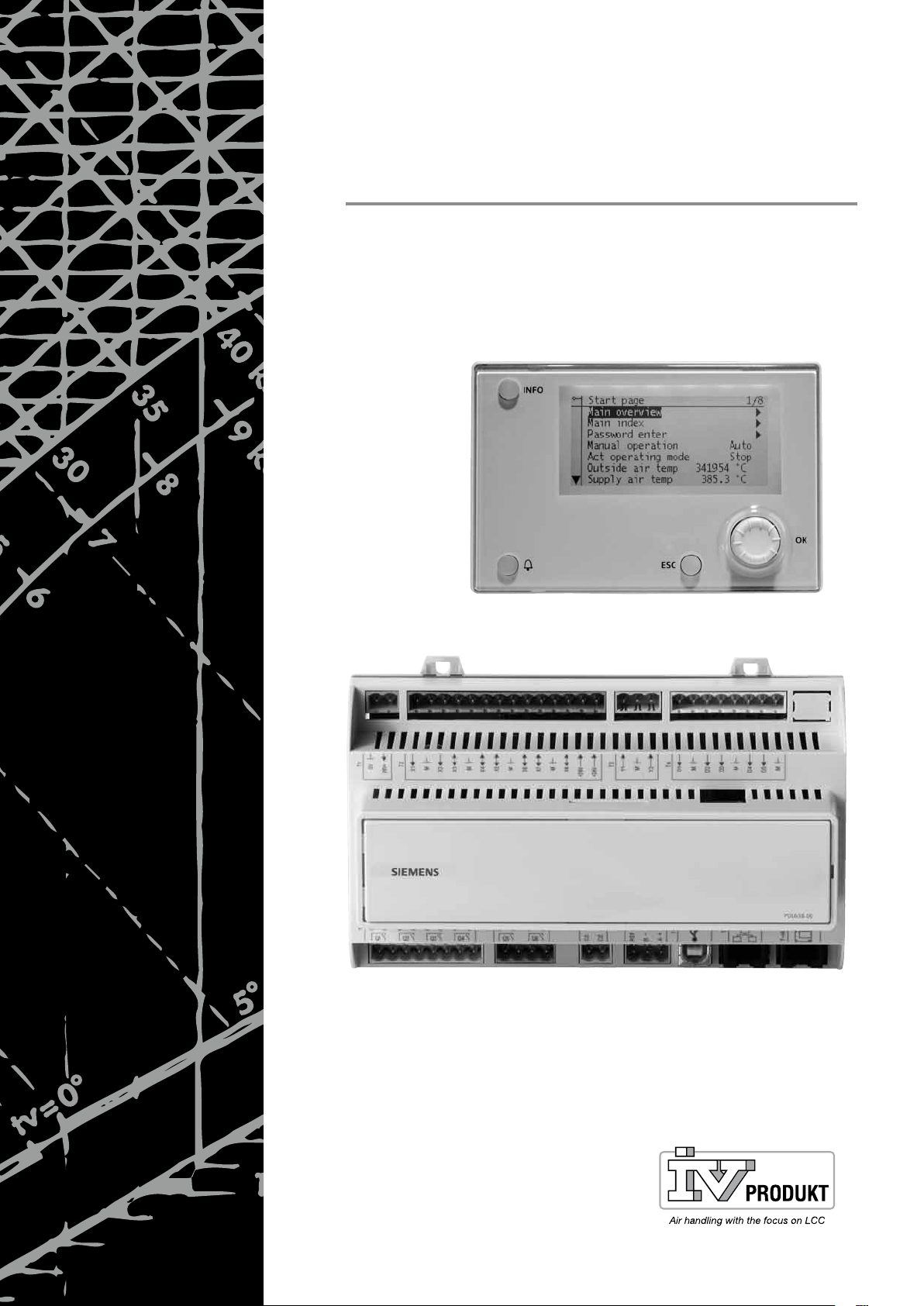
4.3 Inbuild HMI..............................................................................................20
4.4 External HMI (DM) ..................................................................................20
4.5 Room unit................................................................................................25
5 Functions...............................................................................................33
5.1 Global functions ......................................................................................33
5.2 Operating mode ......................................................................................35
5.3 Damper control........................................................................................46
5.4 Fan control ..............................................................................................50
5.5 Temperature control................................................................................59
5.6 Heat recovery damper ............................................................................67
5.7 Heat recovery (Plate, wheel, water)........................................................69
5.8 Heating / Heating 2 .................................................................................73
5.9 Electrical heating / Electrical heating 2...................................................77
5.10 Cooling / Cooling 2..................................................................................79
5.11 Humidity control ......................................................................................83
5.12 Air quality control.....................................................................................90
5.13 Auxiliary functions ...................................................................................91
5.14 Alarm handling (Alarm outputs) ..............................................................93
6 Detail pages: Inputs and outputs.........................................................95
6.1 General ...................................................................................................95
6.2 Analog outputs ........................................................................................95
6.3 Digital outputs .........................................................................................98
Basis Document Siemens Climatix Control System
BDCX.100820.01GB
Page 3
Page 4

6.4 Multistate outputs..................................................................................100
6.5 Analog inputs.........................................................................................102
6.6 Digital inputs..........................................................................................106
7 Detail pages: Controller......................................................................110
7.1 Loop controller ......................................................................................110
7.2 Cascade controller ................................................................................111
8 Detail pages: Time switch program...................................................114
8.1 General..................................................................................................114
8.2 Week scheduler.....................................................................................114
8.3 Day scheduler .......................................................................................115
8.4 Calendar (exception and fixed off)........................................................115
9 Communication ...................................................................................118
9.1 General..................................................................................................118
9.2 Modbus..................................................................................................119
9.3 LON.......................................................................................................124
9.4 BACnet..................................................................................................128
9.5 Room units ............................................................................................131
10 Application Info ...................................................................................135
11 Save / restore parameters ..................................................................136
12 Onboard WEB functionalities ............................................................139
13 System settings...................................................................................141
13.1 Password settings.................................................................................141
13.2 Change passwords ...............................................................................141
13.3 Language Support.................................................................................142
13.4 Target ....................................................................................................142
13.5 Daylight saving time..............................................................................143
13.6 HMI (operating unit) ..............................................................................145
13.7 Diagnostics............................................................................................145
13.8 Diag object handler ...............................................................................146
14 SD card and modem ...........................................................................148
14.1 SD card functions (Update application) ................................................148
14.2 Modem / SMS .......................................................................................149
15 Configuration.......................................................................................152
15.1 Configuration 1......................................................................................154
15.2 Configuration 2......................................................................................159
15.3 Configuration I/Os .................................................................................167
15.4 Check config I/Os..................................................................................176
Page 4
16 Examples..............................................................................................177
17 HMI........................................................................................................177
17.1 Overview ...............................................................................................177
17.2 Start page..............................................................................................177
17.3 Main index.............................................................................................177
Basis Document Siemens Climatix Control System
BDCX.100820.01GB
Page 5

17.4 Main overview .......................................................................................178
17.5 Configuration.........................................................................................178
17.6 Configuration 1......................................................................................178
17.7 Configuration 2......................................................................................180
17.8 Configuration I/Os.................................................................................184
17.9 Check config I/Os..................................................................................188
17.10 Global functions ....................................................................................189
17.11 Inputs ....................................................................................................189
17.12 Operating mode ....................................................................................191
17.13 Damper control......................................................................................194
17.14 Fan control ............................................................................................195
17.15 Temperature control..............................................................................197
17.16 Humidity control ....................................................................................206
17.17 Air qualtity control..................................................................................208
17.18 Auxiliary.................................................................................................209
17.19 Loop controllers.....................................................................................209
17.20 Operation hours ....................................................................................210
17.21 Alarm handling (Alarm outputs) ............................................................211
17.22 Outputs..................................................................................................212
18 Time scheduler....................................................................................213
18.1 Week schedulers...................................................................................213
18.2 Detail pages: Analog outputs ................................................................214
18.3 Detail pages: Digital outputs .................................................................215
18.4 Detail pages: Multistate outputs............................................................216
18.5 Detail pages: Analog inputs...................................................................217
18.6 Detail pages: Digital inputs....................................................................219
19 Alarming...............................................................................................222
19.1 General .................................................................................................222
19.2 Alarm list detail......................................................................................223
19.3 Alarm list ...............................................................................................224
19.4 Alarm history .........................................................................................224
19.5 Alarm list / history settings ....................................................................225
19.6 Alarm lists..............................................................................................226
20 Appendices..........................................................................................230
20.1 Point tables ...........................................................................................230
20.2 Diagnostic tables for check I/O .............................................................232
20.3 Navigation illustrations..........................................................................235
20.4 Parameter list room unit........................................................................239
Index 241
Basis Document Siemens Climatix Control System
BDCX.100820.01GB
Page 5
Page 6

Page 6
Basis Document Siemens Climatix Control System
BDCX.100820.01GB
Page 7
1 About this document
1.1 Revision history
Version Date Changes Section Pages
V1.0 02.07.2009 New document --- --V1.02 18.01.2010 New sub section
New sub section
Revised
4.5 – Room unit
20.4 – Parameter list room device
19.6 – Alarm lists
1.2 Referenced documents
Document title Type of document Document no.
Climatix Controllers POL6XX Documentation on basics CB1P3903en
Climatix Controllers POL63y.XX/XXX Data sheet CB1Q3230de
Climatix Extension Module POL955 Documentation on basics CB1P3920en
Climatix AHU ext. module 14 I/O POL955.XX.XXX Data sheet CB2N3262de
Climatix BACnet communication modules POL904.00/XXX,
POL908.00/XXX
Climatix communication BACnet MS/TP module
POL904.00/xxx
Climatix LON communication module POL906.00/XXX Documentation on basics CB1P3931en
Climatix communication LON module POL906.00/XXX Data sheet CB1Q3931de
Climatix MODBUS communication module POL902.00/XXX Documentation on basics CB1P3934en
Climatix communication MODBUS module POL902.00/XXX Data sheet CB1Q3934de
Documentation on basics CB1P3933en
Data sheet CB1Q3932de
1.3 Before you start
25-33
242-244
229-232
1.3.1 Trademarks
The table below lists the third-party trademarks used in this document and their
legal owners. The use of trademarks is subject to international and domestic provisions of the law.
Trademarks Legal owner
BACnet American National Standard (ANSI/ASHRAE 135-
1995)
LonLink™
LON® / LonManager®
LonMark®
LonTalk®
LonWorks®
MODBUS® The MODBUS Organization, Hopkinton, MA, USA
All product names listed in the table are registered (®) or not registered (™)
trademarks of the owner listed in the table. We forgo the labeling (e.g. using the
symbols ® and ™) of trademarks for the purposes of legibility based on the reference in this section.
Echelon Corporation
Basis Document Siemens Climatix Control System
BDCX.100820.01GB
Page 7
Page 8

1.3.2 Copyright
This document may be duplicated and distributed only with the express permission
of Siemens, and may only be passed on to authorized persons or companies with
the required technical knowledge.
1.3.3 Quality assurance
These documents were prepared with great care.
• The contents of all documents are checked at regular intervals.
• All necessary corrections are included in subsequent versions.
• Documents are automatically amended as a consequence of modifications and
corrections to the products described.
Please make sure that you are aware of the latest document revision date.
If you find any lack of clarity while using this document, or if you have any criticisms
or suggestions, please contact the product manager in your nearest branch office.
Addresses for Siemens RCs are available at www.siemens.com/sbt.
1.3.4 Document use / request to the reader
Before using our products, it is important that you read the documents supplied
with or ordered at the same time as the products (equipment, applications, tools
etc.) carefully and in full.
We assume that persons using our products and documents are authorized and
properly trained and have the requisite technical knowledge to use our products as
intended.
Additional information on products and applications is available:
• On the intranet (for Siemens employees only) at
https://workspace.sbt.siemens.com/content/00001123/default.aspx
• At your
next Siemens branch office www.siemens.com/sbt or at your system
suppliers.
• From the support team in the headquarters fieldsupport-
zug.ch.sbt@siemens.com if no local POC is available.
Siemens assumes no liability to the extent allowed under the law for any losses
resulting from a failure to comply with the aforementioned points or for the improper
compliance of the same.
Page 8
Basis Document Siemens Climatix Control System
BDCX.100820.01GB
Page 9

2 Philosophy of air handling units
2.1 Overview
Climatix OEM controller
product range
Climatix 6xx controller
product range
With the Climatic controller product range for OEM, Siemens is supporting the
trend within the industry to integrate applications for air conditioning and refrigeration technology into the devices at the factory and to lower in this way the costs of
plant installation and commissioning.
The Climatix product range covers all application segments: From standard controllers for simple, cost-optimized HVAC applications such as fan coils to more challenging, communicating applications, up to and including freely programmable
controllers for complex solutions using AHU or chillers that demand a maximum
amount of flexibility for communications and extensions.
All Climatix POL6xx controllers are freely programmable and can be programmed
accordingly for the corresponding use such as ventilation, refrigeration or district
heating.
Various standard applications were created to help OEM customers speed up timeto-market and benefit from our application knowledge and experience in integrating
into the building automation and control system.
The applications are based on years of experience in the corresponding application
segments, are checked and tested and equipped with the required communication
interfaces such as BACnet, LON and Modbus.
The standardization in turn significantly lowers costs at OEM, reduces support expenses as well and guarantees integration into Siemens building automation and
control systems.
2.2 Properties
Climatix standard AHU
application
The application includes all standard as well as special ventilation functions which
can be selected for the OEM and defined using the operator unit (HMI).
The OEM loads the generated parameter file at the end of line test so that the
AHUs are ready to install.
Authorized personnel are also able to enable additional functions in the field to
make it possible to add any desired extensions.
The AHU standard application stands out with its flexible hardware and software,
but also thanks to the standardization of integration.
Basis Document Siemens Climatix Control System
BDCX.100820.01GB
Page 9
Page 10

Use with other components
2.3 Safety
All equipment that is connected to the system must be CE marked and comply with
the Machine Safety Directive.
2.3.1 Requirements regarding personnel for installation and
start-up
Installation and start-up of POL 63X may only be carried out by qualified personnel
who have relevant technical expertise and who are well acquainted with all the
safety and installation regulations.
2.3.2 Safety regulations
The following safety regulations do not relate solely to POL 63X but also to the
regulator’s surroundings (e.g. control panel) and the technical plant in the property.
Observe all safety directions and comply with the corresponding general safety
regulations in order to prevent personal injury and damage to property.
• Safety devices may not be removed, bypassed or taken out of operation.
• Apparatus and system components may only be used in a technically fault-free
state. Faults that can affect safety must be rectified immediately.
• Observe the required safety instructions against excessively high contact
voltages.
• The plant may not be in operation if the standard safety devices are out of
operation or if their effects are influenced in some other way.
• All handling that affects the prescribed disconnection of the protective extra-low
voltage (AC 24 V) must be avoided.
• Disconnect the supply voltage before opening the apparatus cabinet. Never
work when the power is on!
• Avoid electromagnetic and other interference voltages in signal and connection
cables.
• Assembly and installation of system and plant components may only be
performed in accordance with corresponding installation instructions and
instructions for use.
• The following equipment must be protected against static charging: electronic
components, open printed circuit boards, freely accessible connectors and
apparatus components that are connected with the internal connection.
In this context, also observe necessary protective measures such as earthing,
potential equalisation, conducting surfaces (avoid highly insulating materials), etc.
Page 10
Basis Document Siemens Climatix Control System
BDCX.100820.01GB
Page 11

Packing
Transportation
Storage
Cleaning
Faults
2.4 Packing, transport and storage
The required packing of the system for storage and transport is dependent on the
mechanical and climate conditions.
Use the original packaging from Siemens or from the supplier when mechanical
and climate conditions have an impact on transport.
During transport under particularly difficult conditions, a special package must be used.
If the equipment is not to be installed immediately, store it in a well ventilated area,
protected against high temperatures, humidity, dust and metal particles.
• For storage and transport, the limit values specified in data sheet CE2Q3226
always apply.
Contact your supplier or Siemens in the event of any uncertainty.
• Damage that arises as a result of incorrect packing, storage or transport is not
the responsibility of Siemens.
2.5 Maintenance and service
All that is required to maintain POL63x is regular cleaning. System components
that are arranged within the control panel are most easily separated from dust and
dirt in conjunction with the prescribed maintenance checks.
Diagnostics, the rectifying of faults and restarting may only be carried out by
authorised staff. This also applies to work within the control panel (e.g. inspections,
replacing fuses).
In the event of unauthorised interventions, Siemens cannot undertake to honour
any guarantees. The responsibility for any damage that occurs in the system and
any consequential damage rests with whoever caused the damage.
2.6 Environmental protection and waste
Environmental
protection
Waste management
management
Process unit POL 63X has no negative impact on the environment.
The apparatus includes electrical and electronic components and when discarded
must not be handled together with household waste. Always observe local regu-
lations!
2.7 Abbreviations
HMI Human Machine Interface (operating unit)
KP Gain factor (P-effect)
LED Light emitting diode
NC Normally Closed (opening contact)
NO Normally Open (closing contact)
SD Secure device
TN Integral action time (I-time)
Basis Document Siemens Climatix Control System
BDCX.100820.01GB
Page 11
Page 12

3 Function overview
3.1 General
Scope of delivery
Control functions
Implemented communications
Remote o
vice
peration, ser-
• 49 inputs and outputs are available on the base controller POL63x and a maximum of 2 POL955.00/ALG extension modules.
• All functions and the positioning of I/Os are freely configurable on the operator
unit without programming.
• Sensor types (Pt1000, LGNi1000, Ni1000, NTC10k) and the areas for active
sensors are freely selectable.
• Step-by-step configuration. Functions that can no longer be selected are automatically hidden in later steps.
• Disabled functions are hidden on operator units (HMI; HMI4Web) and for comm.
• Support of various languages (currently English, German and Swedish).
• The operating units are password protected and connected over the bus. A sin-
gle HMI possible for multiple controllers.
• Application software update and controller firmware with backup of plant parameters using the SD card.
• Download preconfigured plants using SD cards or a PC with the Saphir Scope
Tool.
• USB interface as the standard connection between the controller and PC.
• Supply air, room and return air and cascade control with optional limitation of
supply air.
• Summer/winter compensation of setpoint.
• External setpoint default or setpoint shift.
• Night start of plant when room temperature with separate setpoint is too low (too
high).
• 4 different heat recovery variants.
• 4 heating registers (2 warm water, 2 electric registers with up to 3 steps, or 0-
10V DC) with up to 3 included in the heating sequence.
• Limitation of electric register dependent on fan speed (stage).
• Preheating for the warm water register, including frost sensor and/or detector.
• 2 cooling registers (cold water or up to 3 stages or analog DX).
• Limitation of direct expansion evaporator dependent on fan speed (stage).
• Shut off cooling register when the outside air temperature is too low.
• Cooling recovery.
• Fresh air and exhaust air damper control.
• Fire damper control with autotest function.
• Extract air fan can be disabled.
• Stepped (maximum 3 steps), frequency controlled or modulating analog controll-
ed fans.
• Emergency off function.
• Time switch catalog with daily, weekly and annual program.
• Modbus RTU or TCP (master, Energy Meter EM24 from Carlo Gavazzi).
• Modbus RTU or TCP (Slave).
• BACnet IP and MSTP.
• LON.
• OPC via TCP/IP or modem.
• Web HMI. (for POL 638.xx only) automatically configured when configuring the
plant.
• Saphir Scope Tool via modem, TCP/IP or LON.
• Alarm messages per e-mail or SMS (GSM modem required).
Page 12
Basis Document Siemens Climatix Control System
BDCX.100820.01GB
Page 13
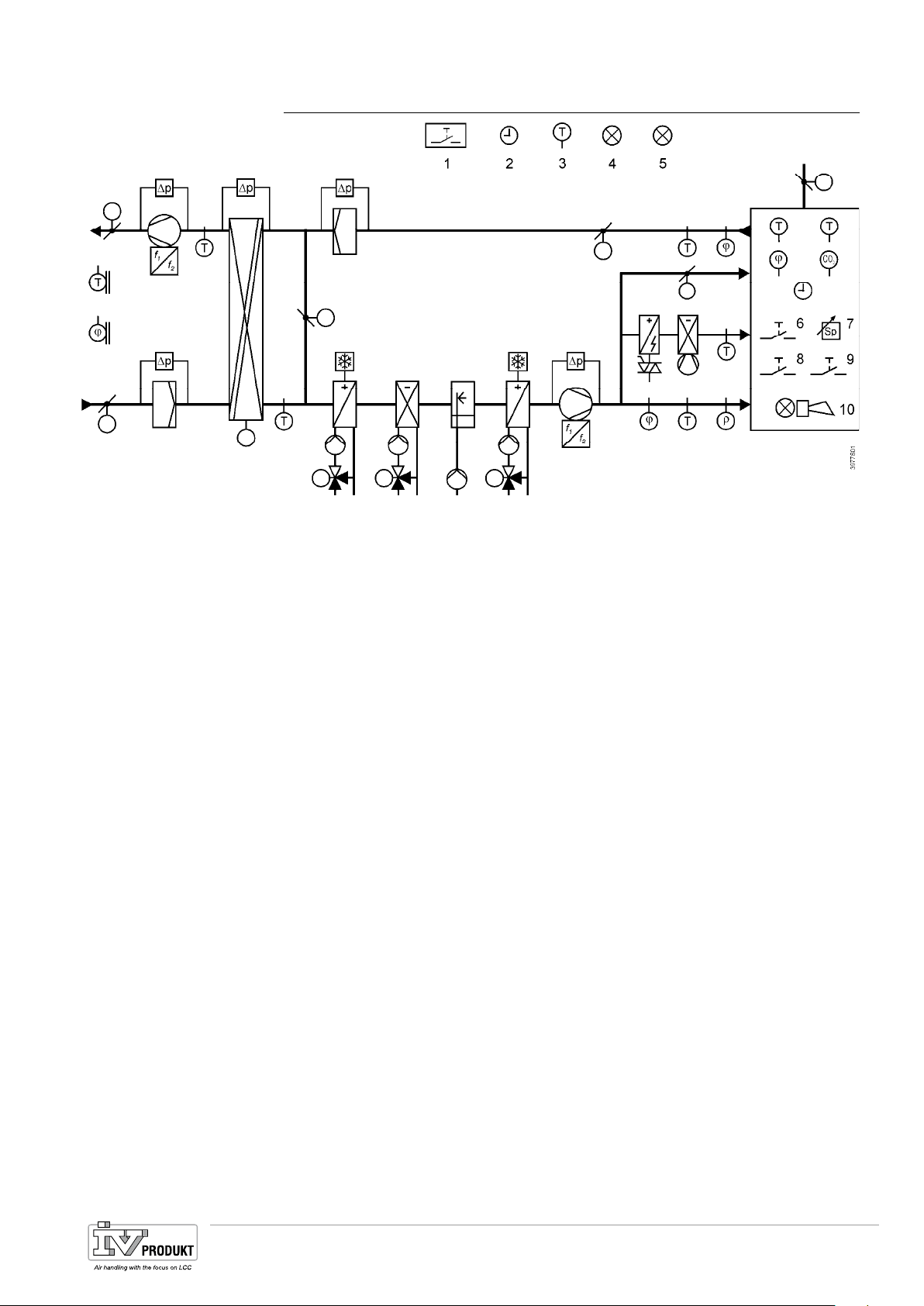
Legend
Heat recovery
3.2 Diagram standard AHU
The figure displays a schematic of the entire functional scope for the standard AHU
application. All aggregates, sensors and functions are selected and configured
when configuring the air handling unit.
− Fire detector
− Time switch program
− Free temperature sensor
− Free alarm display
− Display of certain operating modes
− Occupancy button
− Setpoint settings
− Emergency button
− Acknowledge alarm
− Alarm display
Heat recovery can be implemented in the following ways:
– Rotary heat exchanger.
– Plate heat exchanger.
– Water heat exchanger.
Basis Document Siemens Climatix Control System
BDCX.100820.01GB
Page 13
Page 14
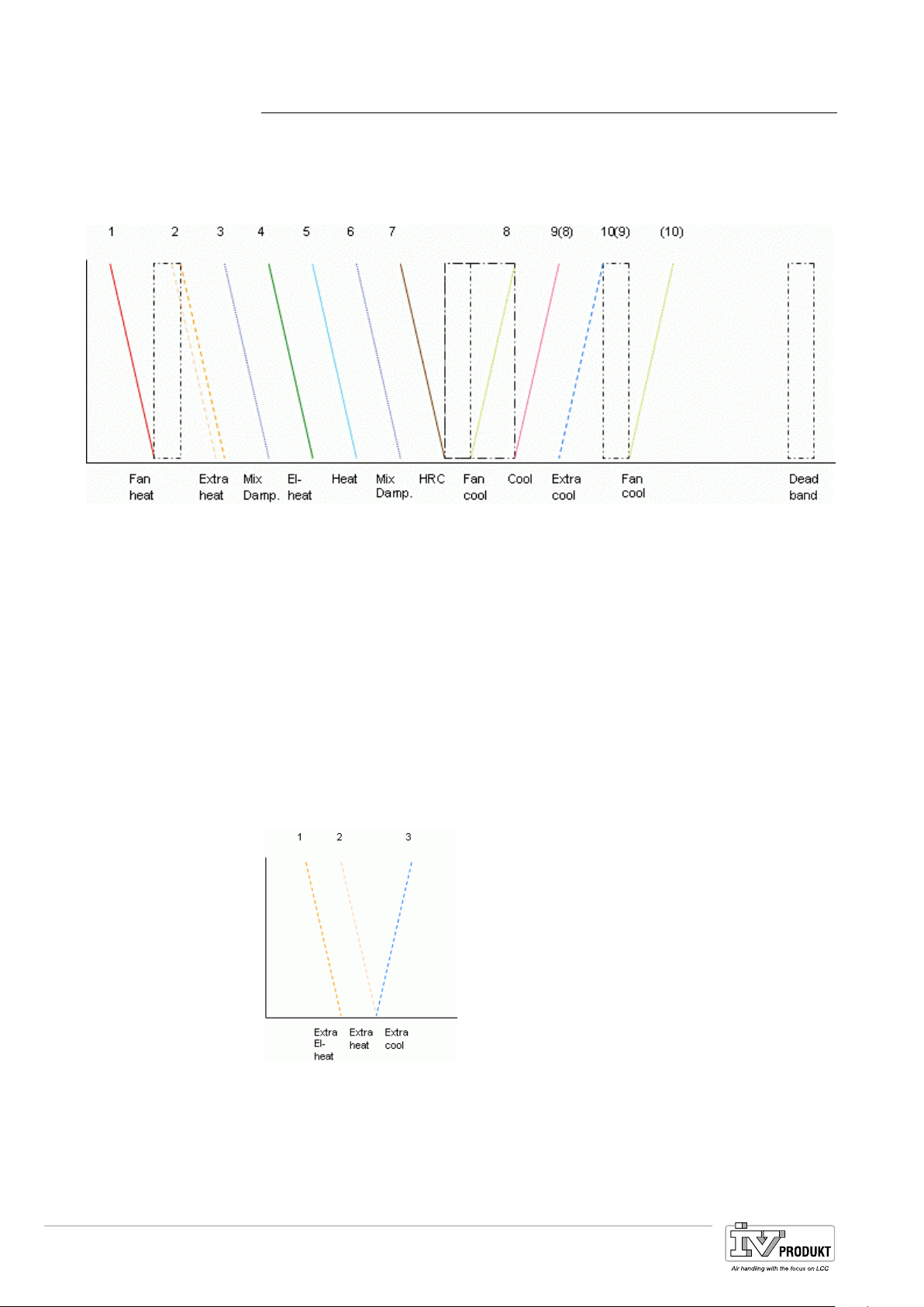
3.3 Workflow diagram
With all aggregates
Legend
Stand alone
• Mixing dampers have changeable placement.
• Fan cooling have changeable placement.
• Deadband between heating and cooling can be changed.
• Fanheat and Fancool have their own changeable deadband.
The figure displays a schematic of all possible sequences included in the application. Individual sequences and series are set automatically during configuration or
for sequence 3, 6 mix damper and 8, 9 fan cool, cooling by configuring the sequence.
1 Fan heating 7 Heat recovery
2 Heating 2 or Electro heating 2 8 Fan cooling
3 Mixing dampers 9 (8) Cooling
4 Electro Heating 10(9) Cooling 2
5 Heating (10) Fan cooling
6 Mixing dampers DB Dead band
Extra sequences can be placed in the normal sequence (above) or as an own
sequence (stand alone):
Legend
Page 14
1 Electro Heating 2
2 Heating 2
3 Cooling 2
Basis Document Siemens Climatix Control System
BDCX.100820.01GB
Page 15
4 Hardware overview
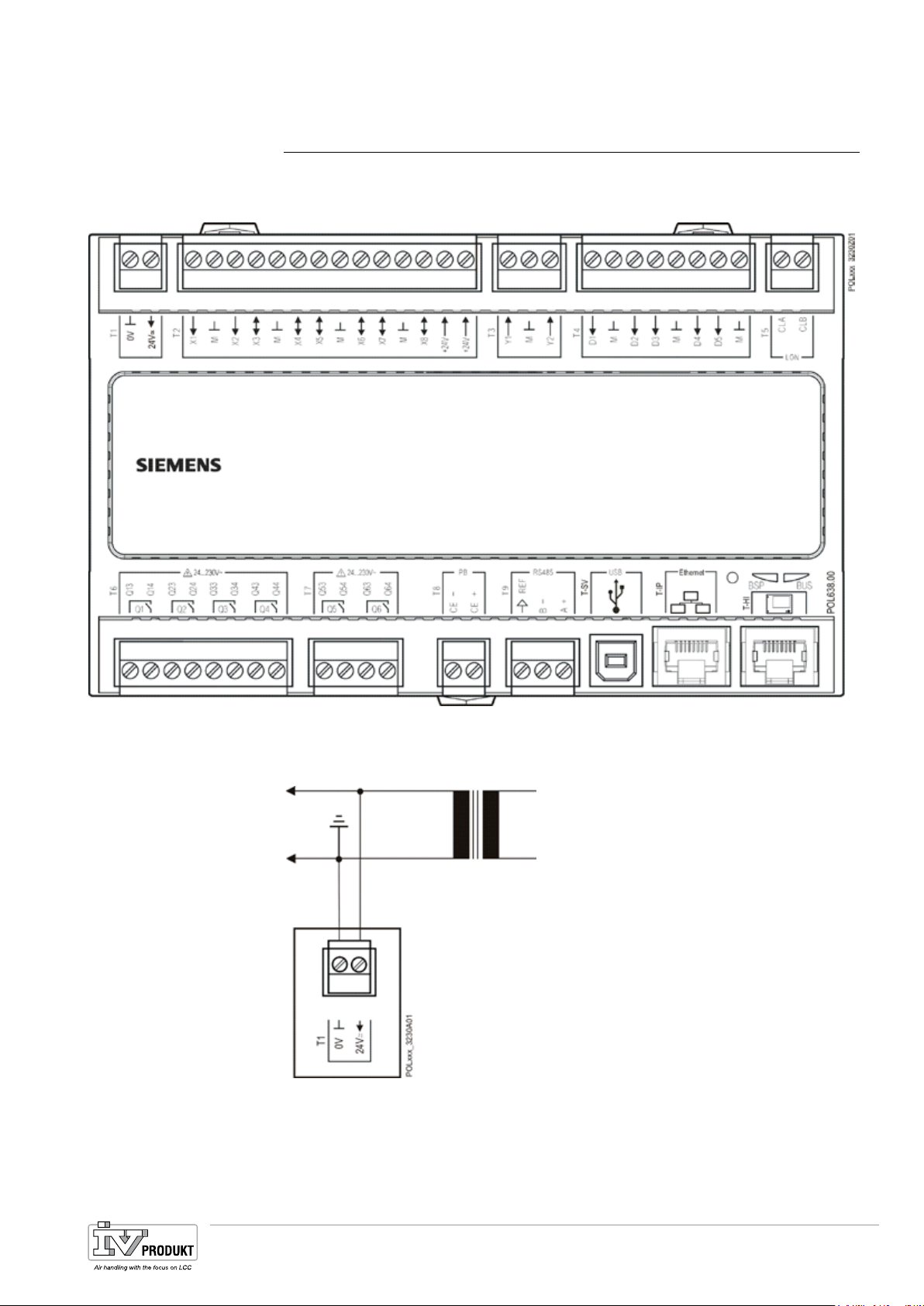
4.1 Basic controller (POL638x)
The exact designation of inputs / outputs in the program or HMI is available in the
point table in the appendix.
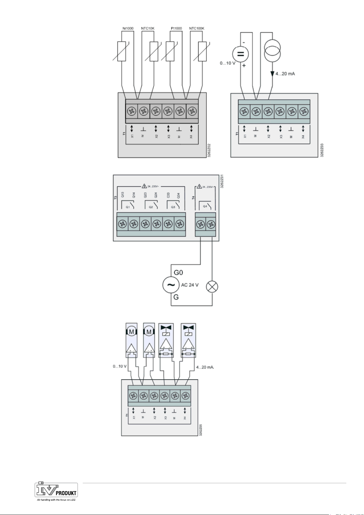
Connection instruction
Power supply
Digital inputs
To connect external components to the process unit, these instructions must be
followed.
X1...X8
Basis Document Siemens Climatix Control System
BDCX.100820.01GB
Page 15
Page 16
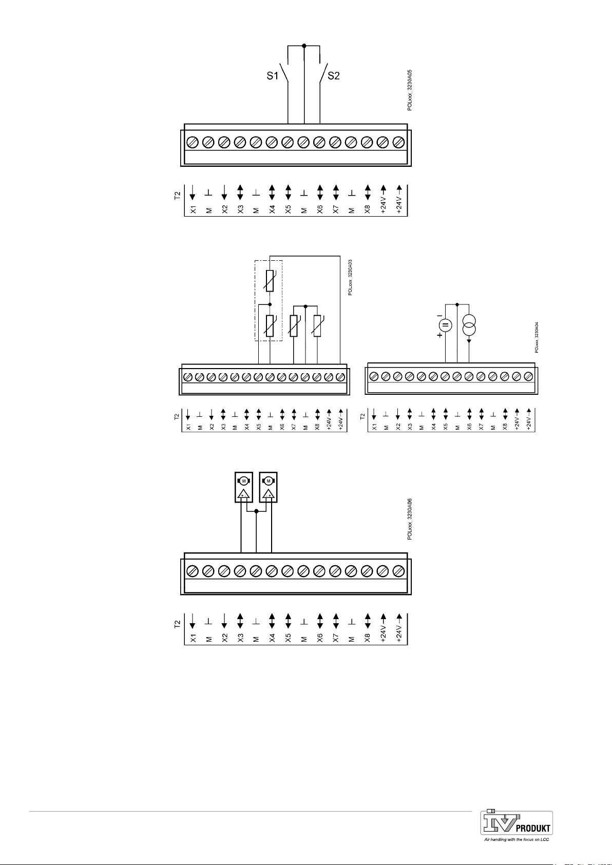
Analog inputs
Analog outputs
X1...X8
X3...X8
Relay outputs
Page 16
Q1...Q6
Basis Document Siemens Climatix Control System
BDCX.100820.01GB
Page 17
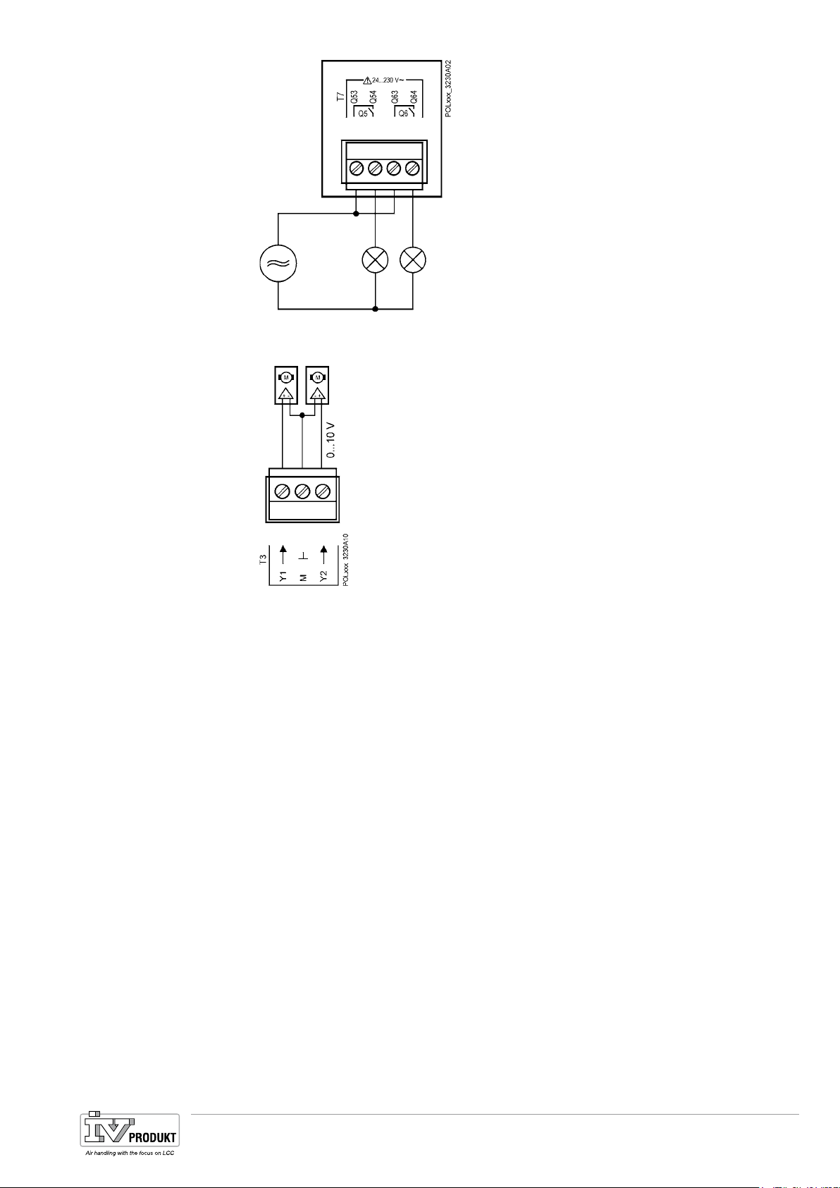
Analog outputs
Y1, Y2
Basis Document Siemens Climatix Control System
BDCX.100820.01GB
Page 17
Page 18
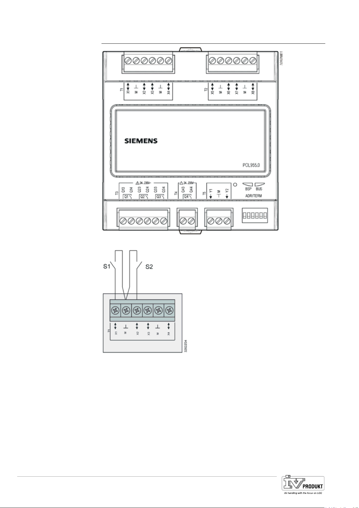
4.2 Extension module (POL955)
Digital inputs
Analog inputs
X1...X8
X1...X8
Page 18
Basis Document Siemens Climatix Control System
BDCX.100820.01GB
Page 19
Relay outputs
Analog outputs
Q1...Q4
X1...X8
Analog outputs
Y1...Y2
Basis Document Siemens Climatix Control System
BDCX.100820.01GB
Page 19
Page 20
4.3 Inbuild HMI
Implemented at a later date.
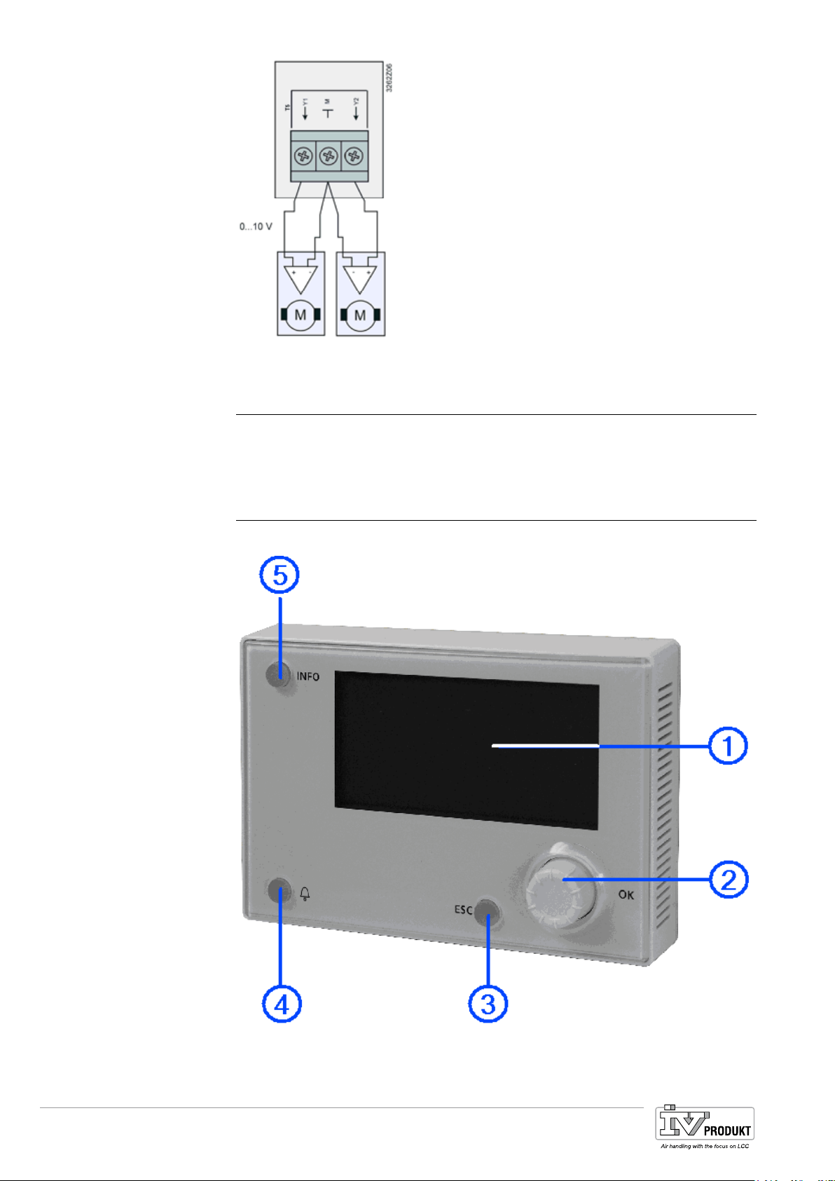
4.4 External HMI (DM)
Operator elements
The external operator unit includes the following operating elements:
Page 20
Basis Document Siemens Climatix Control System
BDCX.100820.01GB
Page 21

Additional information
1. Display
Displays menus, parameters, parameter values, commands, etc.
2. Setting know
• Select menu, parameters, parameter values: Turn.
• Change parameter values: Turn.
• Go to lower levels or to setting pages: Press.
• Exit setting pages and assume changed values: Press.
• Go to password handling page: Press long.
3. ESC button
• Go to the next higher level: Press.
• Exit setting pages and reject changed values: Press.
• Go to start page: Press long.
• Go back to last active page (after going to password handling page using
the setting knob): Press.
• Go back to last active page (after going to Main Index page using the Info
button): Press.
4. Alarm button
LED:
• Off: No alarm.
• Blinking: Alarm pending.
• Lit continuously: Pending acknowledged alarm.
Press button:
• Go to last alarm.
• Go to alarm list (displays pending alarms and alarm history).
• Go to alarm history.
• Go to alarm settings.
• Acknowledge and reset alarms in the alarm list or alarm history.
For more information, refer to section
19
Basis Document Siemens Climatix Control System
BDCX.100820.01GB
Page 21
Page 22

Alarming. page 222.
5. Info but
ton
• Go to Main Index page: Press.
• Go to HMI basis page: Press long.
Page 22
Basis Document Siemens Climatix Control System
BDCX.100820.01GB
Page 23
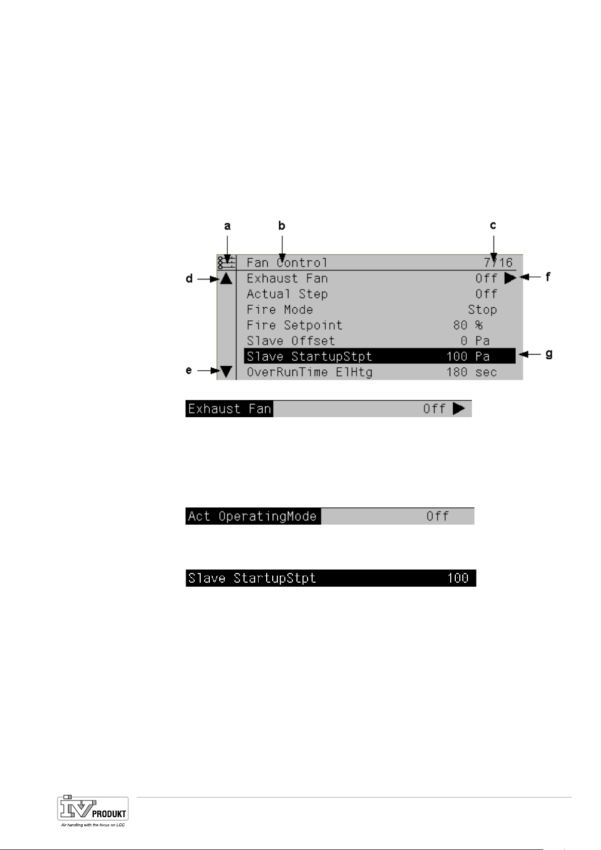
Display
Display design:
a Present access levels:
- No symbol: No Level
- 1st key: Level 6
- 2nd key: Level 4
- 3rd key: Level 2.
b Title of displayed pages.
c 7: Number of selected lines; 16: Number of available lines for the page.
d Page includes additional lines above ---> You can scroll up.
e Page includes additional lines below ---> You can scroll down.
f Another level is located below this line. You can go to it.
g Currently selected line.
Navigation lines
Display line
Setting lines
Set discrete parameter
values.
On navigation lines, the object is highlighted in black when selected. It displays the
present value for a component in front of the navigation arrow.
Navigation:
• Select line: Turn setting knob.
• Switch to level below: Press setting knob.
The object is also highlighted in black when selected for display lines (read only). It
displays the present value for a component.
The parameter name and its present value are highlighted in black for the parameter setting lines.
Set value:
• Select line: Turn setting knob.
• To switch setting page: Press setting knob.
• Set the parameter value on the setting page: Turn setting knob.
• Exit setting page and assume changed parameter values: Press setting knob.
• Exit setting page without saving parameter values: Press ESC.
When only one value is selectable:
Basis Document Siemens Climatix Control System
BDCX.100820.01GB
Page 23
Page 24
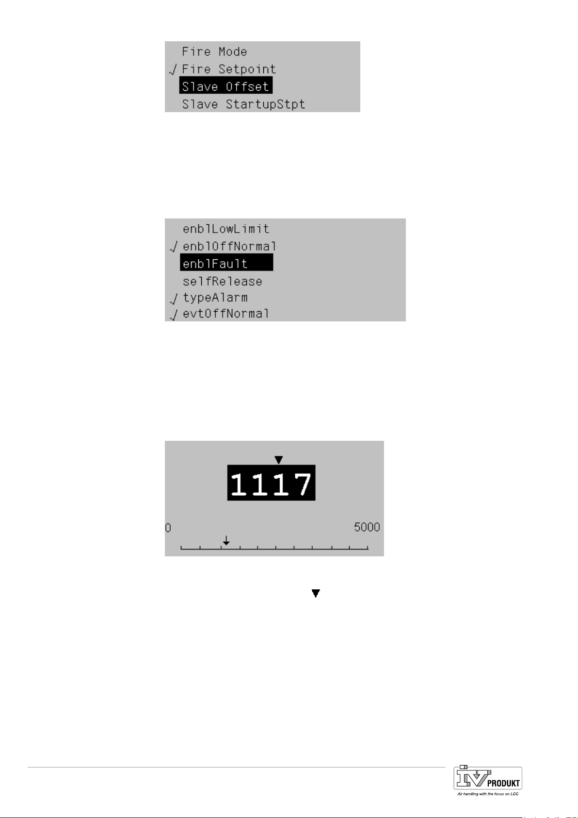
Set analog parameter
values.
The checked off line (Fire Setpoint) displays the presently set value. Changed as
follows:
• Select new value: Turn setting knob.
• Assume new value (and exit setting page): Press setting knob.
or
• Retain old value (and exit setting page): Press ESC button.
When multiple values can be selected:
Checked off lines display presently selected values. Changed as follows:
• Select a value: Turn setting knob.
• Select/deselect value: Press setting knob.
• Assume new selection:
– Select Done: Turn setting knob.
– Select Done: Press setting knob.
or
• Retain old value (and exit setting page): Press ESC button.
Page 24
The scale displays minimum and maximum adjustable values.
Present value changed as follows:
• Adjust number under the arrow
• Move arrow to the left: Turn continuously via a increments of ten
(9--->0 or 0--->9).
• Move arrow to right: Do not turn for about 1 second.
• Assume new value (and exit setting page): Press setting knob.
or
• Retain old value (and exit setting page): Press ESC button.
Basis Document Siemens Climatix Control System
BDCX.100820.01GB
: Turn setting knob.
Page 25
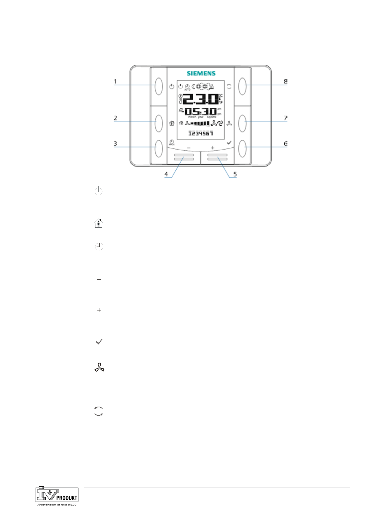
4.5 Room unit
Operating elements
P R OG
The room unit has the following operating elements:
6. (1) On/Off
• Button to changeover from OFF to ON state. Buttons 2-8 are locked and
the display is switched off in the OFF state.
7. (2) Occupancy
• Button to switch on/off a programmed occupancy mode
8. (3) Program
• Long press: Set date and time on the room unit.
• Short press: Change the scheduler program.
9. (4) Minus
• Button to adjust the temperature setpoint. Each push of the button lowers
the temperature setpoint by 0.1 °C/1.0 F or by 0.5 °C/1.0 °F.
10. (5) Plus
• Button to adjust the temperature setpoint. Each push of the button increases the temperature setpoint by 0.1 °C/1.0 F or by 0.5 °C/1.0 °F.
11. (6) OK
• Key to confirm date/time and scheduler program entries.
12. (7) Fan
• Button to adjust plant stage.
Press: The speed is increased by one stage each time you press the button.
13. (8) Mode
It is cyclical: 1-2-3-Auto-1-2-3-Auto, etc.
• Button to select between a maximum of three energy modes: Auto, comfort
and economy.
Press: The mode changes each time you press the button and displayed
with the corresponding symbol.
It is cyclical: Auto – Comfort – Economy – Auto, etc.
Basis Document Siemens Climatix Control System
BDCX.100820.01GB
Page 25
Page 26
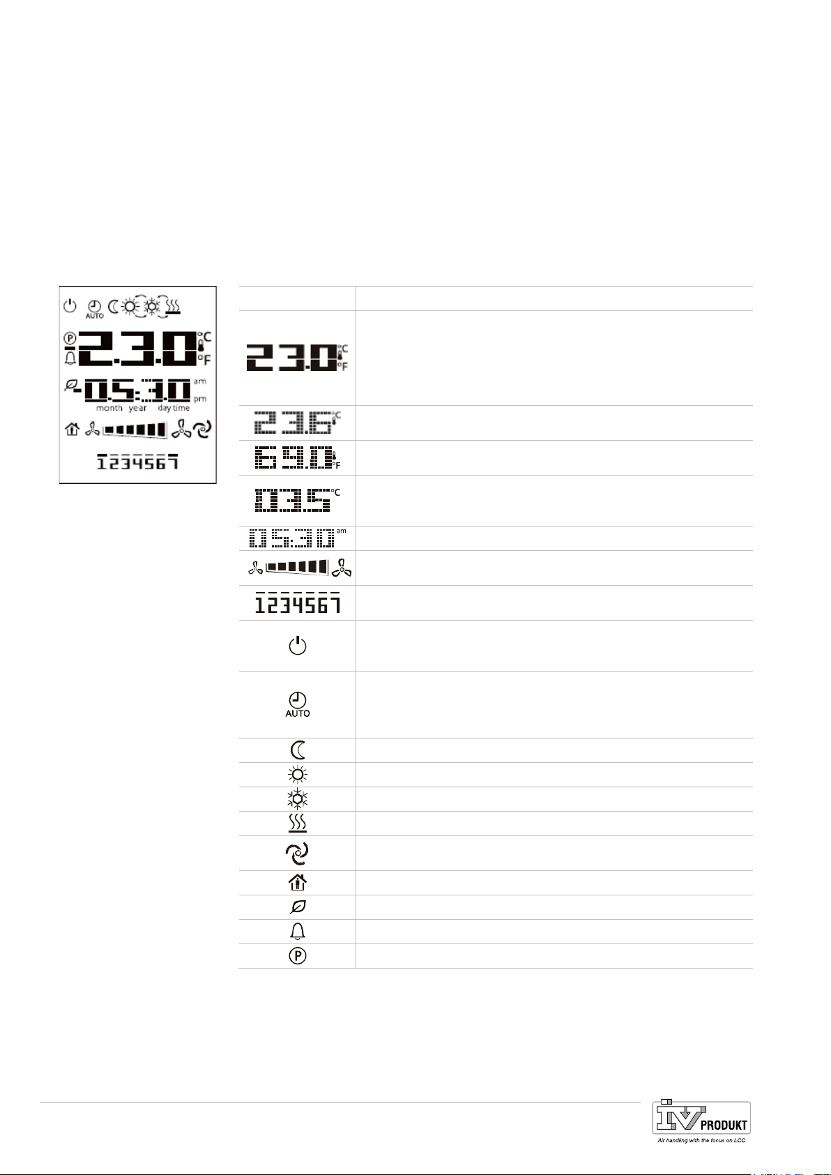
Display
The display shows:
• Selected temperature display
– exhaust temperature, or
– the given room device temperature, or
– mixed room temperature
• Setpoint shift
• Energy mode
• Plant stage
• Time
• Day of the week
The table below displays and explains all the symbols available on the display.
Display
Meaning
Temperature display range
Displays exhaust temperature for the given room device
temperature or the mixed room temperature in °C or °F.
Temperature in °C
Resolution 0.1 °C
Temperature in °F
Resolution 1.0 °F
Setpoint shift
Can be displayed/changed to °C or to °F
Resolution 0.1°C/1.0F or 0.5°C/1.0F
Time
Plant stage
Day of week display (POL822.60/xxx only)
1=Monday
ON/OFF
The device does not fully shut down with OFF, but rather
goes to standby.
Auto mode active
The controller overrides the room device when the symbol
blinks (see 5.2.2 Prioritization operating modes...)
Buttons 1, 2, 5 and 8 are locked.
Economy mode active
Comfort mode active
Cooling
Heating
Automatic plant control
Occupancy mode
Energy tracking
Alarm display
Parameter mode
Page 26
Basis Document Siemens Climatix Control System
BDCX.100820.01GB
Page 27
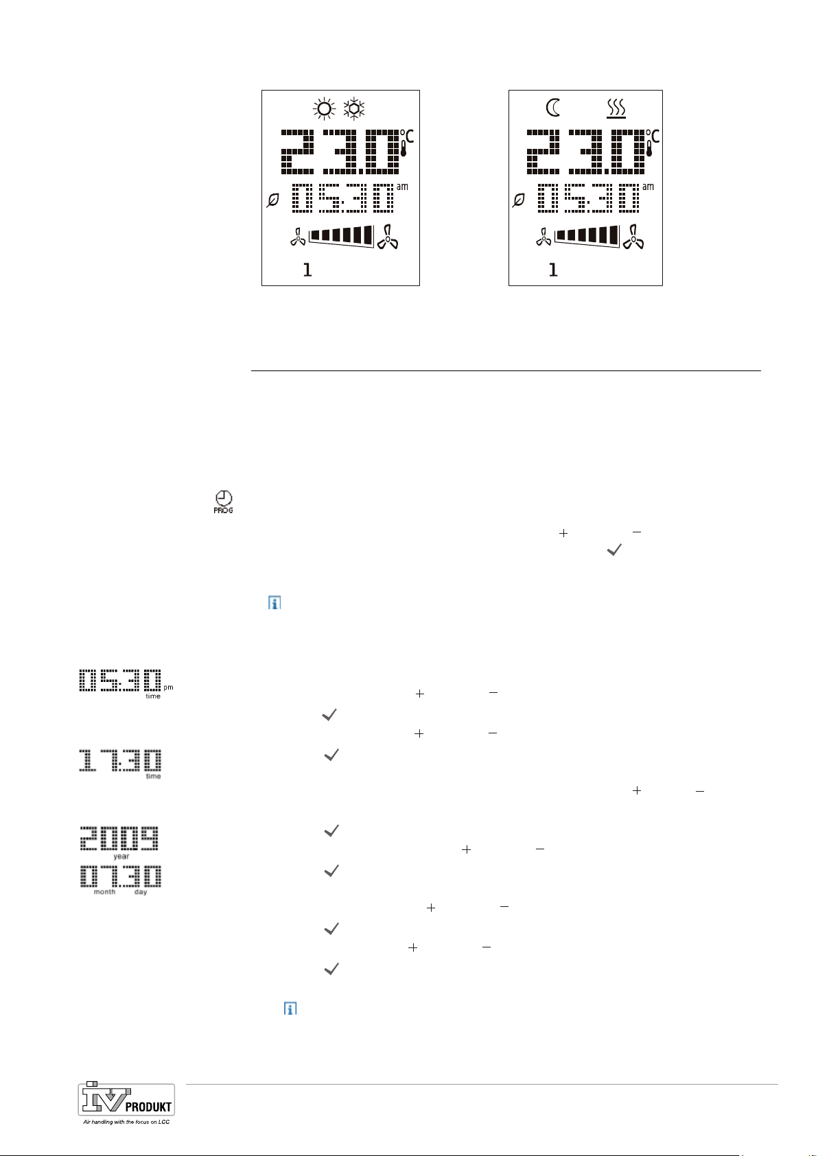
Sample displays
Date and time
Comfort mode, cooling Economy mode, heating
4.5.1 Startup behavior
The room unit initializes automatically after the room unit is connected to the controller and the communication is operating (commissioning is completed). First, all
the symbols appear, then the symbol
returns to normal after a short period. The displays state on P__ if communication
is not properly established (e.g. incorrect room unit address).
User presses the PROG button long (more than 1 second) to enter data and time.
The following applies:
• Flashing parameters can be changed using the
• Changes can (and must) be completed by pressing the
play automatically goes to the next adjustable parameter.
Please note: This is cyclical. The clock blinks again after changing and con-
firming the month and day. You can exit the menu at this point by pressing
the PROG button.
1. Press PROG button long (hour display blinks), then
set the hour with the
2. Taste
set minutes with the
Press OK (the hour is saved and the minute display flashes), then
3. Press
OK button (minutes are saved and the entire time display flashes),
plus and minus buttons.
plus and minus.
then
set the time display format (12/24 hour display; use the
buttons)
4. Press
set the desired year with the
5. Press
OK (the display format is saved and the year display flashes), and
OK (the year is saved and the display shows the month/day display,
the month display blinks), and
set the month with the
6. Press
set the day with the
7. Press
OK (the month and saved and the day display flashes), and
OK (month and day is saved; display returns to the time).
plus and minus buttons.
plus and minus buttons.
8. Press PROG (the display returns to normal).
The display returns automatically to normal when the PROG is not pressed
within one minute.
appears on the display. The display
P__
plus and minus buttons.
OK button. The dis-
plus or minus
plus and minus buttons.
Basis Document Siemens Climatix Control System
BDCX.100820.01GB
Page 27
Page 28

Scheduler function
Program time switch
catalog
Select days of the week
Please note: The room unit does not have an internal clock. The precise time is
periodically synchronized with the controller (master).
The weekly and daily schedule for the time switch catalog (so-called "scheduler")
can be programmed:
• for all 7 days of the week.
• Daily with up to 6 switching entries (referred to as "Entry")
You can do the following when setting up the entries
• determine a switching time and
• select the state to be run in Auto mode.
Possible state assignments (e.g. 0=Off, 1=EcoSt1, 2=ComfSt1, etc.) are predefined as part of the controller configuration. A max. 7 states are possible.
The selected operation is automatically run at the defined time after the entry is
setup.
The following button assignments are enabled when programming the scheduler:
• PROG —> Cancel.
• OK. —> Confirm.
The workflow includes explanations of the individual steps from a technical viewpoint. As a practical matter, individual steps may not be needed, while others must
be repeated, etc. As a result, we are listing an example in this section that illustrates a practical example on programming a room unit.
1. Press PROG
(the display goes to
display through the days of the week).
and flashes; Press plus or minus to quickly cycles the
2. Select weekday with plus and minus (1=Monday), then confirm selection
with OK.
Note: The same settings apply to the selected days. You must proceed
through the entire instruction chain to program different settings for certain
days.
3. Conduct weekdays through day 7 as per step 2.
4. 1 time (!) press the plus button.
You now see the selected days; a flashing bar appears above the numbers.
5. Confirm selected weekdays: 1 time (!) press OK.
The display changes to the first entry page, the state is "00X", time is 00:00
:Do not change the time for this entry!
Three entries per day are prepared and may vary depending on the configured
plant, e.g. State 001 at 00:00 am, state 002 at 08:00 am, state 001 at 6:00 pm. The
entries do not need to be entered in chronological order.
The following illustrates how to create a new (the fourth) entry.
Page 28
Basis Document Siemens Climatix Control System
BDCX.100820.01GB
Page 29

Change schedule
and/or state
Add schedules
Delete schedule
Hints
6. Press plus or minus to select the entry to be changed; click OK to confirm.
Entry is selected, hour display flashes.
7. Set hours to "XX" with plus or minus, then
Press OK.
The minute display flashes.
8. Set minutes to "XX" with plus or minus, then
Press OK.
The state display flashes.
9. Set command to "X" with plus or minus, then
Press OK.
Entry display is static.
10. If other entries required: Repeat steps 6 to 9; you must enter a status each
time.
11. After the final entry: Press OK (status line is idle), then
Finish programming with PROG.
12. Press plus to select entry "Status 000 —:— ", then
Press OK,
the hour display flashes
Then start over at step 7 above.
13. Press plus or minus to select the entry for deletion; click OK to confirm.
Entry is selected, hour display flashes.
14. Disable entry by setting the hour to —:X X,
with X X = any number available in the minute display.
Then press OK
the entry display changes to 000 and —:—
15. If no other changes required:
After the final entry: Press OK (status line is idle), then
Finish programming with PROG.
Up to 7 states can be programmed depending on configuration. They can be assigned, for example, as follows:
Hints
Access levels
Example 1 Example
2
0 = OFF 4 = ComfSt2 0 = OFF
1 = EcoSt1 5 = EcoSt3 1 = Stage 1
2 = ComfSt1 6 = ComfSt3 2 = Stage 2
3 = EcoSt2
Press PROG at any time to return to a previous page when programming the
scheduler.
The room unit returns to normal if no entry is made for longer than 1 minute.
Parameter programming is lost through the last OK, if you return to the normal
page. The same applies when no entries are made on the room unit for more than
1 minute.
4.5.2 Parameters
The room unit distinguishes between 3 access levels:
• Level 6 End users (password 1000).
• Level 4 Service operator (password 2000).
• Level 2 OEM (password 6000).
Basis Document Siemens Climatix Control System
BDCX.100820.01GB
Page 29
Page 30
Group and overall lists
Hints
Parameter mode
Room unit parameter list
The parameters are compiled into three groups.
All available values in the parameter lists affect the application (see
Parameter list room unit , page 239).
includes...
20.4 –
Group
…
Room
S
settings and acknowledge (change be changed depending on the
password).
The most important present values (read only).
U
The main setpoints (may be changed depending on the password).
C
4.5.3 Edit function parameters (parameterization mode)
The function parameters available in the room unit are edited in parameter mode.
The appropriate password required to access it. The following descriptions are
therefore directed in the main toward service personnel.
Use the mode button
In the parameter mode, use the On/Off button to cancel or generally go back
to the previous page.
The room unit returns to normal if no entry is made for longer than 1 minute.
1. Simultaneous press
goes to password entry pages for parameter mode, the first position for the
password flashes.
The symbol
parameter is displayed.
2. Press plus or minus for the first position of the password, then
press Mode.
The first position is saved, the second flashes.
3. Repeat step 2 for the other positions.
After the correct password, after entering the final position, a parameter
group (A, C, S) must be selected on a new page.
For an false password or missing group name, the error message to the
side appears and the first position flashes. Press On/Off
enter the password.
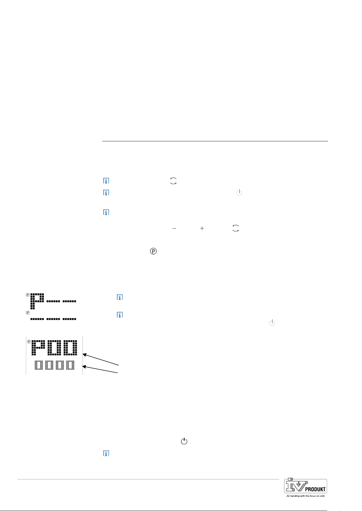
4. Select a group with plus or minus, then press Mode to confirm.
The following is displayed. The following applies:
• Letter = Parameter group.
• Upper line = Parameter-ID.
• Lower line = Parameter value.
5. Press plus or minus to select parameter ID and then press Mode to set the
parameter value.
For RW (read/write) access, the parameter value flashes and can be edited;
the parameter ID line continues to flash for lower rights.
6. Use plus or minus to set parameter value, then
press Mode to confirm.
The insert mark returns to the parameter ID line.
7. Press parameter mode
The room unit parameter list includes all room unit parameters that can be
read/described (see
20.4 – page 239).
to confirm an entry.
minus, plus and mode.
On/Off to exit.
to cancel and re-
Page 30
Basis Document Siemens Climatix Control System
BDCX.100820.01GB
Page 31

Diagnostic mode
Room device parameters
4.5.4 Edit room unit parameters (diagnostic mode)
Room unit parameters for the room unit are edited in diagnostic mode. They impact
only the room unit where the setting is entered and saved. The following descriptions are therefore directed exclusively toward service personnel.
Use the mode button
Use the On/Off button to cancel or generally go back to the previous page.
The room unit returns to normal if no entry is made for longer than 1 minute.
The following local parameters can be viewed/edited in diagnostics mode.
1. Simultaneously press
The display goes to the first diagnostic pages; the following is displayed
• Software version (3 digit) and
• Build number (4 digit).
2. Press
mode.
The display goes to the parameter 1 KNX connectivity (RO)
(parameter overview: see following table)
This parameter cannot be changed (display only).
3. Select additional parameters (0…9) with
Proceed as follows to change a parameter:
• Select parameter (
• Press
mode (parameter value flashes).
• Enter new parameter value with
• Press
mode (parameter flashes).
4. As soon as all parameters are (re-)set: Press
appears.
The individual addresses of multiple HMI devices connected to a network can-
not be the same!
No Room unit parameter/description
001 connectivity (RO)
The KNX connectivity page displays
• OK to indicate that the process bus is active
This is the cases if any data frames are received over the past 70 seconds.
• NG if the process bus is not active.
002
003
004
005
individual addresses – Line address (RW) - (X.1.1).
Address range: 0...15 (is generated automatically, see parameter 9).
individual addresses – address range (RW) - (1.X.1).
Address range: 0...15 (is generated automatically, see parameter 9).
individual addresses – device range (RW) - (1.1.X).
Address range: 1...252 (is generated automatically, see parameter 9).
geographic address apartment (RW) - (X.1.1).
Numbering range for apartment: 1...126.
Default value set to 5 (only requires change if multiple controllers are operated with room devices on one bus) see as well Main Index > Integrations >
Room units Settings > Room zone.
to confirm an entry.
on/off, minus, plus and mode.
minus or plus.
minus or plus, parameter flashes).
minus or plus.
on/off until the main page
Basis Document Siemens Climatix Control System
BDCX.100820.01GB
Page 31
Page 32

Alarm display
No Room unit parameter/description
006
geographic address room (1.X.1).
Numbering range for room: 1...14.
007
Default value set to 1.
geographic address sub zone (RW)(1.1.X).
Numbering range for sub zone: 1...15.
This value must be changed from default 1 to 2 for two room units on the
same controller.
008
¨
Network error recognition on/off (RW).
Parameter to turn on/off the network error recognition function, with
0 = off (P__ is displayed when no data frames are received in the last 70
seconds and the function is turned on).
1 = On.
NET flashes, when no data frames are received over the past 70 seconds
and the function is turned on.
Timeout Network error recognition during parameter initialization: 30
seconds.
009 Automatic assignment of individual addresses on/off (RW).
0 = The room unit uses the unit devices as a fixed assigned individual ad-
dress.
1 = Automatic addressing on the process bus
The room unit changes as required (e.g. for address conflict on the
process bus) the individual address via DAA mechanism (Detect And
Avoid mechanism)
Default value 1 = automatic addressing
When the controller sends an alarm to the room unit, the
• Alarm is displayed
• Depending on parameterization, the alarm number, including the grouping, flash-
es, or only the alarm is displayed
A = Alarm switched off,
B = Normal alarm,
C = Warning
Details see
19.6 – Alarm lists and 9.5 – Communication room unit
Page 32
Basis Document Siemens Climatix Control System
BDCX.100820.01GB
Page 33

5 Functions
5.1 Global functions
5.1.1 General
This section describes special functions that related to the application as a whole.
Prerequisites
Parameters
Parameter Range Function
Su-Wi calculation
Manual mode
Enable manual alarm
Enable comm test Function not yet available.
Communication test Function not yet available.
None.
Main Index > Global functions
– Summer
– Winter
– Auto
– Manual
– No
– Yes
Displays present status for summer and winter operation.
Go to page to parameterize summer/winter
changeover.
Displays whether one of the outputs is not in auto
mode (intervention via HMI), a sensor is out of service or the manual operation mode is not on auto.
Go to page with all digital inputs, e.g. to set the
alarm class for enabled manual alarm.
– Auto mode: No element in manual mode or out
of service.
– Manual mode: At least one element is in manual
operation or out of service.
Enables an alarm if when Manual mode = Manual.
– No alarm trigger.
– Alarm trigger.
5.1.2 Summer Winter changeover
Prerequisite
Function
None.
It decides whether the plant is in summer or winter operation based on various options (hardware input, date, temperature). This information is required (as an option) to shut down humidification in summer, to changeover the Combi Coils and to
changeover temperature control (Tmp control mode = RmSplyC Su or RtSplyC Su).
A hardware input enabled for the changeover (Main Index > Configuration > Configuration 1 > Su/Wi input = Yes) has the highest priority (Signal 1 = Summer).
The temperature or date can affect the changeover depending on parameterization. Both criteria must be met when both are enabled. There is no changeover and
the plant in continuously in winter operation when no criterion is enabled.
Basis Document Siemens Climatix Control System
BDCX.100820.01GB
Page 33
Page 34

Parameter
Main Index > Global functions > Su/Wi calculation
Parameter Range Function
State
Su/Wi input
– Winter
– Summer
– Winter
– Summer
Status of Summer/Winter changeover:
– Winter operation is enabled.
– Summer operation is enabled.
Status of input on hardware side for changeover.
Go to page with all digital input settings. For example, you can change the input’s direction of control
there.
– Winter operation enabled: Signal 0.
– Summer operation enabled: Signal 1.
Outs air tmp damped Damped outside air temperature.
Summer date / time *.* *:* Set date and time for changeover to summer op-
eration.
Example:
23:30 01.Apr ---> Changeover on April 1 at 11:30
pm.
– Asterisks only (*.* *:*): Changeover date is not
relevant; changeover occurs based on temperature.
– Permissible time entries:
*:* ---> 00:00
*:20 ---> 00:20
10:* ---> 10:00.
– Date entry:
Allowed: 15.May
Not allowed by month: Odd / Even.
Winter date / time *.* *:* Set date and time for changeover to winter opera-
tion.
Example:
10:40:00 PM 01.Oct ---> Changeover on October
1 at 10:40 pm.
Note: See summer date / time
Time constant 0…36000 [h] Time constant to calculate dampened (determined
over this period) outside air temperature. Set this
value for the short period to 0 to reset the damp-
ened or assume present outside air temperature.
Outs air tmp summer -64...64 [°C] Changes over to summer operation when the
damped outside air temperature is greater than this
value.
Outs air tmp winter -64...64 [°C] Changes over to winter operation when the
damped outside air temperature is less than this
value.
Page 34
Basis Document Siemens Climatix Control System
BDCX.100820.01GB
Page 35

5.2 Operating mode
5.2.1 General
Purpose
Function to set and display all settings for the operating mode in question, i.e. start
conditions, switch-off conditions, operating mode. The plant may also be control
using the HMI.
Prerequisites
Parameterization
None.
None.
The configuration in Configuration1 and Configuration2 provide the various ways to
switch on the plant.
Displays/settings
Main Index > Unit > Operating Mode
Parameter Range Function
Actual
Manual operation
– Off
– On/Comfort
– Economy.
– Na
– Osstp
– NightClg
– UnOcc
– NightKick
– FireDamper
– Fire
– Stop.
– OverRun
– StartUp
– Auto
– Off
– Stage 1
– Stage 2
– Stage 3
– Auto
– Off
– Eco St1
Plant operating state:
– Plant is switched off.
– Plant operating in Comfort Mode.
– Plant operating in Economy Mode.
– Available operating mode, currently unused.
– Optimum start (boost function active).
– Night cooling, active.
– Not used (temperature start at night) heating or
cooling active.
– Night kick active for the plant to update the duct
temperature.
– Fire damper test running.
– Plant in fire mode (depending on the parameteri-
zation of Fire mode).
– Plant stopped and locked(Controller in Startup-
Phase, Configuration not Done; HighClass
Alarm; Emergency Stop).
– Fan overrun.
– Plant in start-up routine.
Manual plant operation via HMI (only possible for
Tsp function <> Steps+Tmp).
– Auto mode: Time switch catalog, night cooling,
etc., can switch on the plant.
– Plant off.
– Plant operating in stage 1 (using setpoint stage 1
for analog controlled plants).
– Plant operating in stage 2 (using setpoint stage 2
for analog controlled plants).
– Plant operating in stage 3 (using setpoint stage 3
for analog controlled plants).
Manual plant operation via HMI (only possible for
Tsp function = Steps+Tmp).
– Auto mode: Time switch catalog, night cooling,
etc., can switch on the plant.
– Plant off.
– Plant operating in Economy at stage 1 (using
setpoint stage 1 for analog controlled plants).
Manual operation (cont.)
– Comf St1 – Plant operating in Comfort mode at stage 1 (us-
Basis Document Siemens Climatix Control System
BDCX.100820.01GB
Page 35
Page 36

Parameter Range Function
– Eco St2
– Comf St2
–
– Eco St3
– Comf St3
ing setpoint stage 1 for analog controlled plants).
– Plant operating in Economy at stage 2 (using
setpoint stage 2 for analog controlled plants).
– Plant operating in Comfort mode at stage 2 (us-
ing setpoint stage 2 for analog controlled plants).
– Plant operating in Economy at stage 3 (using
setpoint stage 3 for analog controlled plants).
– Plant operating in Comfort mode at stage 3 (us-
ing setpoint stage 3 for analog controlled plants).
Time switch program
– Off
– Stage 1…Stage 3
Displays current command for time switch catalog
(for Tsp function = Steps only).
Jumps to page to parameterize time switch catalog.
Time switch program
From BACS
– Off
– Eco
– Comf
– Auto
– Off
– Stage 1
– Stage 2
– Stage 3
– Auto
– Off
– Eco St1
– Comf St1
– Eco St2
– Comf St2
– Eco St3
– Comf St3
Displays present command for time switch catalog.
(for Tsp function = Steps+Tmp only).
Jumps to page to parameterize time switch catalog.
Displays plant command from BMS (for TspFunction <> Steps+Tmp only). The value may also be
operated using HMI even when communication not
connected.
– Auto mode: Time switch catalog, night cooling,
etc., can switch on the plant.
– Plant off.
– Plant operating in stage 1 (using setpoint stage 1
for analog controlled plants).
– Plant operating in stage 2 (using setpoint stage 2
for analog controlled plants).
– Plant operating in stage 3 (using setpoint stage 3
for analog controlled plants).
Displays plant command from BMS (for TspFunction = Steps+Tmp only). The value may also be
operated using HMI even when communication not
connected.
– Auto mode: Time switch catalog, night cooling,
etc., can switch on the plant.
– Plant off.
– Plant operating in Economy at stage 1 (using
setpoint stage 1 for analog controlled plants).
– Plant operating in Comfort mode at stage 1 (us-
ing setpoint stage 1 for analog controlled plants).
– Plant operating in Economy at stage 2 (using
setpoint stage 2 for analog controlled plants).
– Plant operating in Comfort mode at stage 2 (us-
ing setpoint stage 2 for analog controlled plants).
– Plant operating in Economy at stage 3 (using
setpoint stage 3 for analog controlled plants).
Plant operating in Comfort mode at stage 3 (using
setpoint stage 3 for analog controlled plants).
Page 36
Basis Document Siemens Climatix Control System
BDCX.100820.01GB
Page 37

Parameter Range Function
External control
Roomunit op mode
– Auto
– Off
– Stage 1
–
– Stage 2
– Stage 3
– Auto
– Comfort
– Standby
Displays current plant command from hardware
plant switch.
– Auto mode: Time switch catalog, night cooling,
etc., can switch on the plant.
– Plant off.
– Plant operating in stage 1 (using setpoint stage 1
for analog controlled plants).
– Plant operating in stage 2 (using setpoint stage 2
for analog controlled plants).
– Plant operating in stage 3 (using setpoint stage 3
for analog controlled plants).
Displays present plant command from room unit
– Auto mode: Time switch catalog, night cooling,
etc., can switch on the plant.
– Plant operating in Comfort Mode.
– Plant is in standby.
– Plant operating in Economy Mode.
– Economy.
Night kick exh tmp
--- Starts plant to update sensor values for return-air
controlled plant and activated night cooling or UnitStart TmpDelta.
(Temperature difference start). Jumps to page to
parameterize night kick.
Night cooling
--- Night cooling (free cooling). Jumps to page to parameterize night cooling.
Tmp start
--- Starts plant at night based on temperature difference. Jumps to page to parameterize temperature
difference start.
Boost
--- Boost plant start. Jumps to page to parameterize
boost plant start.
Power up delay
0…36000 [s] Delayed plant start after controller restart.
Basis Document Siemens Climatix Control System
BDCX.100820.01GB
Page 37
Page 38

5.2.2 Prioritize various operating modes and switch-on sequences
OpMode
Display of various operating modes: Disabled functions and elements are ignored.
Page 38
Basis Document Siemens Climatix Control System
BDCX.100820.01GB
Page 39

Start sequence
Plant start sequence. Disabled functions and elements are ignored.
Fire
Conditions to trigger a fire alarm.
Basis Document Siemens Climatix Control System
BDCX.100820.01GB
Page 39
Page 40

Stop
Conditions that stop the plant:
Configuration
by Download
No
Configuration 1
Done
Configuration 2
Done
Configuration I/
O
Done
Configuration
I/O Doubled
No Fault
Configuraion
I/O not
configured
OK
Yes
Not Done
Not Done
Not Done
Fault
Not OK
Controller
Power up
Emergency
Stop
Alarm
High Class
0
Release Stop
Aktiv
Passive
Aktiv
Inaktiv
Aktiv
Inaktiv
STOPP
Page 40
Basis Document Siemens Climatix Control System
BDCX.100820.01GB
Page 41

5.2.3 Time switch program
Prerequisite
A time switch catalog is enabled:
Main Index > Configuration > Configuration 1 > TSP function <> No
Function
The plant is controlled via the time switch program.
Parameter
Main Index > Unit > Operating mode > Time switch program
Parameter Range Function
Schedule
– Off
– Stage1…Stage3
Present plant operating mode from the time switch
catalog for Tsp function <= Steps. Goes to details
page to parameterize time switch catalog.
Schedule – Off
– Eco St1…Eco St3
– Comf St1…Comf St3
Calendar exception – Passive
– Active
Present plant operating mode from the time switch
catalog for Tsp function = Steps+Tmp. Goes to details page to parameterize time switch catalog.
Calendar for vacation and holidays. The entry for
the exception day of the scheduler is enabled when
this entry is enabled. Goes to details page to parameterize time switch catalog.
Calendar fix off – Passive
– Active
Additional calendar to switch off the plant. Goes to
details page to parameterize second calendar.
5.2.4 External Control (parameterize plant switch)
Prerequisite
The external plant switch is enabled:
Main Index > Configuration > Configuration 1 > Ext control input <> None
Function
Plant operation via external plant switch, presence detectors or buttons (Ext control
input 1, Ext control input 2). The plant can be switched to auto mode, a set stage or
to off depending on parameterization and configuration. The command defaulted
here is only enabled when no higher priority command is not active, e.g. Manual
Operation is enabled via HMI.
Parameter
Main Index > Unit > Operating mode > External control
Parameter Range Function
Actual mode
– Auto
– Off
– Stage 1
– Stage 2
– Stage 3
Actual plant operating mode as triggered by the plant switch.
– Auto mode: Time switch catalog, night cooling, etc., can
switch on the plant.
– Plant off.
– Plant operating in stage 1 (using setpoint stage 1 for analog
controlled plants).
– Plant operating in stage 2 (using setpoint stage 2 for analog
controlled plants).
– Plant operating in stage 3 (using setpoint stage 3 for analog
controlled plants).
Basis Document Siemens Climatix Control System
BDCX.100820.01GB
Page 41
Page 42

Parameter Range Function
Tmp stpt input 1
– Comfort
– Economy.
Applied temperature setpoint at the active input Ext control
input 1; enabled only for Tsp function = Steps+Tmp.
– Comfort setpoint.
– Economy setpoint.
Note: The present temperature setpoint is determined by the
value from Tmp stpt input 2 if both inputs are enabled.
Tmp stpt input 2
– Comfort
– Economy.
Applied temperature setpoint at the active input Ext control
input 2; enabled only for Tsp function = Steps+Tmp.
– Comfort setpoint.
– Economy setpoint.
See not for Tmp stpt input 1!
Off delay 0…23.0 [h]
Switch-off delay. Plant goes to auto mode after the delay.
Notes:
– Off delay = 0 ---> The present command is pending as long
as the impacted input is enabled. This is mandatory for
plant switches.
– Off delay > 0 ---> Is used exclusively for external buttons or
presence detectors that requires resetting the plant to auto
mode after a set period.
Fan steps
– Auto
– Off
– 1Step
– 2Step
– 3Step
Select fan step:
– Auto mode.
– Plant off.
– Plant operating in stage 1 (using setpoint stage 1 for analog
controlled plants).
– Plant operating in stage 2 (using setpoint stage 2 for analog
controlled plants).
– Plant operating in stage 3 (using setpoint stage 3 for analog
controlled plants).
Start/stop function
– Off
– On
Define input functions:
– Each pulse on the input start the Timer Off delay.
– The first pulse on the input starts the Timer Off delay and
sets the command. The next pulse resets to auto mode.
The same applies when the timer expires.
Fan steps function
• Main Index > Configuration > Configuration 1 > Ext control input = One --->
Only input Ext control input 1 is enabled. The command set with fan steps is issued when Ext control input 1 = On.
• Main Index > Configuration > Configuration 1 > Ext control input = Two --->
Both inputs Ext control input 1 and Ext control input 2 are enabled. In this case:
– Ext control input 1 = Off and Ext control input 2 = Off ---> Command = Auto
mode.
– Ext control input 1 = Off and Ext control input 2 = Off ---> Command = 1Step.
– Ext control input 1 = Off and Ext control input 2 = On ---> Command = 2Step.
– Ext control input 1 = On and Ext control input 2 = On ---> Command as de-
termined by fan step.
Page 42
Basis Document Siemens Climatix Control System
BDCX.100820.01GB
Page 43

Start/stop function and of
f
delay
• Start/stop function = Off and Off delay = 0 ---> The command is issues as long
as the signal is pending.
• Start/stop function = Off and Off delay > 0 ---> The command is issued during
the off delay period for a pulse at the input. The timer restarts for each new
pulse on the input.
• Start/stop function = On and Off delay = 0 ---> The command is issued for a
pulse on the input and then reset against at the next pulse.
• Start/stop function = On and Off delay > 0 ---> The command is issued for a
pulse on the input and then reset against at the next pulse or after the off delay
period.
5.2.5 Night kick function
Prerequisite
Function automatically enabled when the following conditions are met:
– Non room sensor available and
– the return tmp sensor is not parameterized as saved and
– Night cooling or start is enabled based on the temperature difference:
Main Index > Configuration > Configuration 1 > Room tmp sensor = No
and
Main Index > Configuration > Configuration 1 > Exh air tmp sensor = Yes
Und
Main Index > Configuration > Configuration 2 > Night cooling = Yes
Main Index > Configuration > Configuration 2 > Tmp start <> No
Function
Plant kick ramps up the plant after a longer period of inoperation to update the
measured return temperature in the duct.
This temperature is used as the decision-making criterion to start night cooling or
temperature difference start and should be kept updated as much as possible.
Parameter
Main Index > Unit > Operating mode > Night kick exh tmp
Parameter Range Function
Kick time
00:00...23:59 Time to execute kick.
Example:
23:00 Kick is run at 11:00 pm.
*:* Time is not relevant; the interval applies accordingly.
Interval time 0.0…36000.0 [h] Interval time to execute kick.
Example:
3.0 Run every 3 hours.
0.0 Interval is not relevant; kick time applies accordingly.
On time 0...36000 [s] Kick period.
Example
Kick time = 23:00 / Interval time = 3 / On time = 300
---> The plant is switched-on for 300 seconds if the plant has been off for at least 3
hours as of 11:00 pm.
Note
Kick time = *:* and interval time = 0.0 h ---> No plant kick is triggered.
Basis Document Siemens Climatix Control System
BDCX.100820.01GB
Page 43
Page 44

5.2.6 Night cooling (Free Cooling)
Prerequisite
Function
Note
Night cooling (free cooling) is enabled.
Main Index > Configuration > Configuration 2 > Night cooling <> No
Night cooling cools down a building at night using cool outside air without auxiliary
energy for high daytime temperatures.
• Night cooling is switched on in the following cases:
– Outside air temperature is greater than the lower level: Out tmp > Min outs
tmp
and
– Outside air temperature is less than the difference from room temperature and
switch-on differential: Out tmp < Room tmp - Delta
and
– Room temperature is greater than the sum of the room setpoint and hystere-
sis: Room tmp > Room tmp setpoint + hysteresis.
• Night cooling is switched off in the following cases:
– Timer Min run time = 0
and
– Plant switches on.
or
– Outside air temperature is less than the difference from room temperature and
switch-off differential: Out tmp > Room tmp – 1 or
– Room temperature is less than or equal to room setpoint: Room tmp <= Room
tmp setpoint
The function is disabled for faulty outside air or room temperature.
Parameter
Main Index > Unit > Operating mode > Night cooling
Parameter Range Function
Room tmp setpoint
-64.0…64.0 [°C] Room setpoint for night cooling. Setpoint applies to return air
for night cooling with a return air sensor.
Hysteresis 0.0…64.0 [°C] Hysteresis for switch on.
Delta 1.0…64.0 [°C] Minimum difference between room and outside air tempera-
ture.
Min outs tmp -64.0…64.0 [°C] Minimum outside air temperature to activate night cooling.
Min run time 0…999 [min] Minimum runtime after a start.
5.2.7 Temperature difference start
Prerequisite
Function
Plant start by temperature difference is enabled:
Main Index > Configuration > Configuration 2 > Tmp start <> No
Plant night start based on temperature difference prevents the building from cooling down or heating up too much. It is controlled to a separate setpoint for heating
and cooling.
The heating and or cooling start can be enabled separately:
Main Index > Configuration > Configuration 2 > Tmp start
Page 44
The function can be implemented using a return air sensor if no room sensor is
available.
Basis Document Siemens Climatix Control System
BDCX.100820.01GB
Page 45

Cooling demand
Heating demand
Note
The plant night start by temperature difference for cooling demand occurs when
the following conditions are met:
– Room tmp > Start stpt cooling und
– Timer Minimum off time = 0
The shutdown occurs for:
– Room tmp < Start stpt cooling - Hysteresis
The plant night start by temperature difference for heating demand occurs when
the following conditions are met:
– Room tmp > Start stpt heating und
– Timer Min off time = 0
The shutdown occurs for cooling demand occurs for:
Room tmp > Start stpt heating + Hysteresis
The function when the room temperature sensor (return air sensor) fails.
Parameter
Main Index > Unit > Operating mode > Tmp start
Parameter Range Function
Start stpt cooling
-64.0….64.0 [°C] Start temperature for cooling.
Cooling setpoint -64.0….64.0 [°C] Cooling setpoint.
Start stpt heating -64.0…64.0 [°C] Start temperature for heating.
Heating setpoint -64.0….64.0 [°C] Heating setpoint.
Hysteresis 0.1…64.0 [°C] Shutdown hysteresis.
Minimum off time 0…999 [min] Minimum switch-off time after active heating or cooling.
Min run time 0.0…..999.0 [min] Minimum runtime after a start.
5.2.8 Boost function (boost plant start)
Prerequisite:
Function
Boost is enabled:
Main Index > Configuration > Configuration 2 > Boost <> No
Boost ensures a comfortable room temperature when the plant is switched on normally.
The heating and or cooling start can be enabled separately:
Main Index > Configuration > Configuration 2 > Boost
Cooling demand
Heating demand
Note
The function can be implemented using a return air sensor if no room sensor is
available.
Boost for cooling demand occurs when the following conditions are met:
– Room tmp > Start stpt cooling + Hysteresis and
– Time to normal start via the time switch program < Compensation time
The shutdown occurs for:
– Room tmp < Start stpt cooling
Boost for heating demand occurs when the following conditions are met:
– Room tmp < Start stpt heating - Hysteresis and
– Time to normal start via the time switch program < Compensation time
The shutdown occurs for:
– Room tmp > Start stpt heating
The function when the room temperature sensor (return air sensor) fails.
Basis Document Siemens Climatix Control System
BDCX.100820.01GB
Page 45
Page 46

Parameter
Main Index > Unit > Operating mode > Tmp start
Parameter Range Function
Room tmp setpoint
Start stpt cooling
-64.0…64.0 [°C] Boost room setpoint.
-64.0….64.0 [°C] Start temperature for cooling.
Start stpt heating -64.0…64.0 [°C] Start temperature for heating.
Hysteresis 0.1…64.0 [°C] Shutdown hysteresis.
Compensation time 0…999 [min] Time by which plant start is advanced.
5.2.9 Optimum Start Stop Function
Not yet available.
5.3 Damper control
5.3.1 General
Prerequisite
Dampers are enabled in configuration 1, configuration 2 and configuration I/Os,
preconfigured and the inputs, outputs defined.
Enable
Main Index > Configuration > Configuration 1
Parameter Range Function
Damper – No
– Combined
– Supply
– Supply+Exh
Fire damper – No
– Yes
– FollowUnit
– No opening/closing of dampers.
– Two dampers with common output.
– Outside air damper with output.
– Two dampers with separate outputs.
– No fire dampers.
– Fire dampers.
– Fire dampers are opened with Unit Start or
closed with Unit Stop.
Configuration
Main Index > Configuration > Configuration 2
Parameter Range Function
Damper fdbk – No
– One
– Two
– No damper feedback.
– Feedback for outside air dampers (or a common
feedback for both dampers).
– Separate feedback for outside air and exhaust air
damper.
Fire damper fdbk
– Closed
– Clsd+Opnd
– Combined
Fire damper feedback.
– Only one feedback for close.
– Two separate feedbacks for open and close.
– Two feedbacks for open and close, but only one
signal. The syntax must be correct:
1 (close) ---> 0 (moving) ---> 1 (open)
Parameterization
Main Index > Unit > Damper Control
Parameter Range Function
Off delay by fanoff 0…36000 [s] Switch-off delay for outside air, exhaust and fire
dampers. The dampers are closed after this period
after switching off the supply air fan.
Page 46
Basis Document Siemens Climatix Control System
BDCX.100820.01GB
Page 47

Parameter Range Function
Damper --- Jump to damper page to parameterize the outside
and exhaust air damper.
Fire damper – On
– Off
Current fire damper status. Jump to fire damper
page to parameterize the fire damper.
5.3.2 Supply / Exhaust damper
Prerequisite
Air and exhaust air dampers are enabled and preconfigured in configuration 1, configuration 2 and configuration I/Os.
Function
Per settings outside and exhaust air damper open at plant start and close at plant
stop. Damper opening times can be defined separately. A common default period
can be set if no damper feedback exists. The damper command can still be kept at
pending for a feedback alarm.
Only the output for the outside air damper is enabled if two dampers are enabled
as combined. This is also true for triggering feedback alarms for the exhaust air
damper, if a separate feedback per damper is enabled.
Outside damper is forced by the supply fan. Exhaust damper is forced by the
exhaust fan. If combined damper is selected, then the output for ouside damper is
forced by both supply fan or exhaust fan. Take care if for example Firemode
RunExh is used.
Parameter
Main Index > Unit > Damper Control > Damper
Parameter Range Function
Outside air cmd
Outside air fdbk
Off
On
No
Yes
Current state of outside air damper command. Go
to page with all digital output settings.
Active feedback as to whether the damper is open.
Go to page with all digital input settings. For example, you can set the time for jitter protection (Default: 5 s).
Outs offby fdbk alm
No
Yes
Determines, in the event of a feedback fault,
whether a damper command is still pending or
whether to switch off the command.
StrtUpDly outs fdbk
0…36000 [s] Defines the period after an open command without
feedback before a feedback alarm is triggered. Jitter time is enabled exclusively if the feedback is
pending after this period.
Extract air cmd
Extract air fdbk
Off
On
No
Yes
Current state of exhaust air damper command.
Go to page with all digital output settings.
Active feedback as to whether the damper is open.
Go to page with all digital input settings. For example, you can set the time for jitter protection (Default: 5 s).
Extr offby fdbk alm
No
Yes
Determines, in the event of a feedback fault,
whether a damper command is still pending or
whether to switch off the command.
StrtUpDly Extr fdbk
0…36000 [s] Defines the period after an open command without
feedback before a feedback alarm is triggered. Jitter time is enabled exclusively if the feedback is
pending after this period.
Opening time 0…36000 [s] Estimates damper opening time for both dampers, if
Basis Document Siemens Climatix Control System
BDCX.100820.01GB
Page 47
Page 48

Note
not active feedback (fdbk) is enabled. It is assumed
that the dampers are open after this period and that
the start release is issued for the fans.
Feedback can only be used as alarm, when Contact function = NO (Normally
Open) and the element is set to ON.
5.3.3 Fire damper
Prerequisite
Fire dampers are enabled and preconfigured in configuration 1, configuration 2 and
configuration I/Os.
Function
Fire dampers can be driven together with the plant, with automatic test or they are
always open. Reaching and leaving the given end switch is monitored. Displays the
current state and operating state of the dampers.
Fire damper is forced by both supply fan or exhaust fan.
Parameter
Main Index > Unit > Damper Control > Fire damper
Parameter Range Function
Command – Off
– On
Feedback opened – No
– Yes
Current state of outside air damper command.
Go to page with all digital output settings.
Active feedback if the damper is open. The feedback
opened is automatically set after 115% of open time
if fdbk Open is not enabled in configuration 2.
Feedback closed – No
– Yes
No move – OK.
– alarm
Active feedback if the damper is closed. This feedback must always be available.
Alarm message no reaction occurs to both feedbacks after a change in the damper command. See
example below.
State
– NotDefined
– Closed
– Move
– Opened
Current damper state.
– Only possible during configuration.
– Closed.
– Moving.
– Opened.
See example below.
Mode
– NotDefined
– Ok
– Debug
– Alarm
Damper operating state.
– Only possible during configuration.
– Okay.
– In test mode.
– In alarm state.
Opening time 1…600 [s] Positioning time to open the damper (See Data-
sheet damper actuator).
Closing time 1…600 [s] Positioning time to close the damper (See Data-
sheet damper actuator).
Start manual test – Passive
– Active
Auto test Uhrzeit, Wochentag,
Datum
Active triggers a manual test of the fire dampers.
See examples below.
Determines the time for an automatic start of the
damper test. The automatic test is disabled for Configuration 1 > Fire damper = FollowUnit.
See examples below.
auto test interval 0...36000 [h] Set the time interval for a period automatic damper
test.
See examples below.
Page 48
Basis Document Siemens Climatix Control System
BDCX.100820.01GB
Page 49

Examples of no move
and state
Examples of manual test,
auto test,
auto test interval
Note:
Damper command 0 1:
• After 15% of Open Time, fdbk must be Closed = No, otherwise a no move alarm
is triggered.
• After 115% of Open Time, fdbk must be Opened = Ok, otherwise a fdbk Open
alarm.
Damper command 1 0:
• After 15% of Close Time, fdbk must be Opened = No, otherwise a no move
alarm occurs.
• After 115% of Close Time, fdbk must be Close = Ok, otherwise a fdbk close
alarm.
The automatic test can be set to a time (day, time) and / or conducted periodically.
• Auto test = *:* *,*.* / Auto test interval = 24 --->
A test is conducted every 24 hours regardless of the time.
• Auto test = 23:* Mo,*.* / Auto test intervall = 47 h --->
A test is conducted each month at 11:00 pm to the extent the last test is older
than 47 hours.
Auto test = *:* *,*:* und Autotest interval = 0 --->
No automatic test is conducted.
Test flow (manual or
automatic)
Connection intruction
Pending command = 1
– Test Start
− Mode goes to test, the entire unit is stopped. After the period Off delay by fanoff,
outside and exhaust air dampers are closed and the fire damper test is started.
− The command switches to: 1 0
After 15% of Close Time, Fdbk must be Opened = No, otherwise no move
alarm.
After 115% of Close Time, fdbk must be Closed = Ok, otherwise a fdbk close
alarm.
− If everything is OK: Command switches to: 0 1
After 15% of Open Time, Fdbk must be Closed = No, otherwise no move alarm.
After 115% of Open Time, fdbk must be Opened = Ok, otherwise a fdbk opened
alarm.
− If everything is OK: Mode goes to OK; the unit is restarted.
Connection instruction for indication of smokedampers
Closed
Open
Closed
Open
DI3
STOP
Smoke dampers must be connected as the instruction above for correct
functionality.
Basis Document Siemens Climatix Control System
BDCX.100820.01GB
Page 49
Page 50

5.4 Fan control
This section deals with the topics fans, air flows, air pressures and associated control, such as pressure control.
5.4.1 Configuration
Prerequisite
The main air control functions are enabled, preconfigured and the inputs/outputs
are defined in confuration1 and configuration 2 and Configuration I/Os. Exhaustfan
should be set to “combined” if combined outputs for the supply fan and exhaust are
wanted, and set to “no” if no exhaust fan.
Enable
Main Index > Configuration > Configuration 1
Parameter Range Function
TSP steps Enable possible fan steps.
– 1Step
– 2Steps
– 3Steps
– Single-step fan (only one setpoint).
– 2-step fan (two setpoints).
– 3-step fan (three setpoints).
Fan control mode Select fan and control type.
– Direct
– DirectVar
– FixedSpeed
– Pressure
– Flow
– SupplySlv
– ExhaustSlv
– Digitally controlled stepped fans.
– Digitally controlled variable speed drives.
– Stepped analog controlled variable speed drive with digital re-
lease [%].
– Pressure-controlled plant with modulating controlled variable
speed drive and digital release [Pa].
– Volume-controlled plant with modulating controlled variable
speed drive and digital release [l/s].
– One digital and analog output each for the variable speed drives
in pressure-controlled plants where the supply air fan operates
dependent on the exhaust fan [Pa]/[l/s]. The exhaust fan is
pressure controlled and the exhaust flow is calculated, the
supply fan is flow controlled to follow the exhaust flow.
– One digital and analog output each for the variable speed drives
in pressure-controlled plants where the exhaust air fan operates
dependent on the supply air fan [Pa]/[l/s]. The supply fan is
pressure controlled and the supply flow is calculated, the
exhaust fan is flow controlled to follow the supply flow.
Configuration
Main Index > Configuration > Configuration 2
Parameter Range Function
Fan steps freq conv Activation of additional digital outputs depending on the selected
fan type. Function available only for analog controlled variable
speed drives (Fan control mode <> Direct or DirectVar). The switch
does not affect air control and fan behavior.
– 1Step
– 2Steps
– Enable variable speed drive (always active).
– Output for optional wiring depending on fan step 2.
– Outputs for optional wiring depending on fan step 3.
– 3Steps
Page 50
Basis Document Siemens Climatix Control System
BDCX.100820.01GB
Page 51

Parameter Range Function
Fan steps type Coding of digital outputs for fan control.
The number of outputs and possible Stepps (setpoints) depends on
the setting in TSP steps and also FanStep FreqConv, for analog
controlled variable speed drives.
Refer to explanation under General Operating Modes.
– Separated
– SepCombin
e
– Binary
– On digital output per stage and fan.
– Separate outputs on the first step, common outputs for addi-
tional steps.
– Outputs for the steps are binary coded. The setting is permitted
for Fan Type = direct or directVar.
Parameterization
Main Index > Unit > Fan Control
Functions not enabled in Configuration 1 and/or Configuration 2 are hidden.
Parameter Range Function
Supply fan – Off
– Stage 1
Current supply air fan status. Go to parameter page for supply
air fan.
– Stage 2
– Stage 3
Exhaust fan – Off
– Stage 1
Current exhaust air fan status. Go to parameter page for exhaust
air fan.
– Stage 2
– Stage 3
Actual step – Off
Current calculated, valid stage (setpoint for control) for fans.
– Stage 1
– Stage 2
– Stage 3
Fire mode
– Stop.
– RunSply
– RunExh
Fan behavior in the event of a fire alarm:
– Fans are off.
– Only the supply air fan starts at the maximum enabled stage.
– Only the exhaust air fan starts at the maximum enabled stage.
– Both fans start at the maximum enabled stage.
– Run both
Fire setpoint 0…100 [%] Output signal for fan start in the event of a fire alarm for all ana-
log controlled variable speed drives.
Slave offset -999….999 [Pa] Setpoint offset for fan control mode = Supply Slv or Exhaust Slv.
Slave start up stpt 0….999 [l/s]
Start setpoint for fan control mode = Exhaust Slv for exhaust fan
until the supply air fan is operating. The exhaust air fan then op-
erates using the Slave Offset setpoint.
Rundown time el htg 0…36000 [s] Supply air fan overrun if an electrical heating register is active.
Min stage time 0…999 [s]
Minimum runtime for a stage prior to stepping up to the next
step.
Note: This period remains active when intervening using the op-
erator unit: Even for a direct jump from off to stage 3, the output
remains on each individual step for the minimum runtime.
Coasting time 0..99 [s] Coasting time when reducing each stage.
Basis Document Siemens Climatix Control System
BDCX.100820.01GB
Page 51
Page 52

Parameter Range Function
Disable high speed -64.0…64.0 [°C] Stages greater than 1 (setpoint stage 1) are blocked (as with
manual operation) if the outside air temperature < Disable HighSpeed. All possible stages are enabled for outside air temperature > Disable HighSpeed + 1K. In Winter (at low outside air
temperature) the function prevents too great a volume of air from
discharging requiring heating, saving energy in this manner.
Disable fan comp
– None
– St4age 1
Limit to compensated step up (step up switching):
– No limit. For active stage 1 can be switched to stage 2, for
active stage 2 to stage 3. For analog controlled variable speed
drives (Fan control mode <> Direct or DirectVar), can be
stepped up per curve (see Fan compensation) for active
stage1 setpoint and stage2 setpoint.
– Compensation blocked for active stage 1(Stage1 setpoint).
Can be switched to stage 3 for active stage 2.
For analog controlled variable speed drives (Fan control mode
<> Direct or DirectVar), can be stepped up per curve (see Fan
compensation) for active stage2 setpoint.
– Compensation blocked for active stage 1 and active stage 2.
For analog controlled variable speed drive the active stage 3
can be compensated to MaxForce.
– St4age1+Stage
2
Summer comp -100….100% Present value for summer compensation. Go to parameter page
for summer compensation.
Winter comp -100….100% Present value for winter compensation. Go to parameter page for
winter compensation.
Op hours settings Go to parameter page for fan maintenance messages.
5.4.2 General Operating Modes
Fan steps type =
Separated
Fan steps type =
Separated (Forts.)
The following relationship apply among the values for the parameters fan control
mode, TSP steps, fan step freq conv and fan steps type.
Fan control mode = Direct/DirectVar
DO1 DO2 DO3
Off 0 0 0
Stage1 1 0 0
Stage2 0 1 0
Stage3 0 0 1
DOs each for supply fan and exhaust fan (if
selected)
Fan control mode <> Direct/DirectVar, Fan steps freq conv = 1
DO1
Off 0
Stage1 1
Stage2 1
Stage3 1
DO1 each for supply fan and exhaust fan (if
selected)
Fan control mode <> Direct/DirectVar, Fan steps freq conv > 1
DO1 DO2 DO3
Off 0 0 0
Stage1 1 0 0
Stage2 1 1 0
DOs each for supply fan and exhaust fan (if
selected)
Page 52
Basis Document Siemens Climatix Control System
BDCX.100820.01GB
Page 53

Fan steps type =
SepCombine
Fan steps type = Binary
Note
Stage3 1 0 1
Fan control mode = Direct/DirectVar
DO1 DO2 DO3
Off 0 0 0
Stage1 1 0 0
Stage2 0 1 0
Stage3 0 0 1
– DO1 each for supply fan and exhaust fan (if
selected)
– DO2, DO3: Combined output for both fans
Fan control mode <> Direct/DirectVar, Fan steps freq conv = 1
In this case, fan steps freq conv = 1 has no impact, since output DO1 is always available for supply and exhaust air fan.
DO1
Off 0
Stage1 1
Stage2 1
Stage3 1
DO1 each for supply fan and exhaust fan (if
selected)
Fan control mode <> Direct/DirectVar, Fan steps freq conv > 1
DO1 DO2 DO3
Off 0 0 0
Stage1 1 0 0
Stage2 1 1 0
Stage3 1 0 1
– DO1 each for supply fan and exhaust fan (if
selected)
– DO2, DO3: Combined output for both fans
Fan control mode = Direct/DirectVar
DO1 DO2
Off 0 0
Stage1 1 0
Stage2 0 1
Stage3 1 1
DOs each for supply fan and exhaust fan (if
selected)
For all frequency controlled fans: Stage = active setpoint
5.4.3 Supply / Exhaust fan Control
Configuration
Supply air fan is always available; cannot be disabled. Only the exhaust air fan
must be enabled:
Main Index > Configuration > Configuration 1
Parameter Range Function
Exhaust fan – No
– Yes
– Combined
– No exhaust air fan.
– Exhaust air fan with separate outputs.
– Exhaust and supply air fan with common outputs.
Function
Fans can be operated staged, pressure-controlled, flow controlled and as masterslave. Common or separate outputs are used depending on the configuration.
Function (cont.)
Fans may include an alarm and/or active feedback contact.
Up to 3 setpoints per fan can be defaulted for controlled fans and achieving the
setpoints can be monitored.
You can influence the fan stage (speed) by room temperature, air quality, humidity,
outside air temperature or supply air temperature.
Basis Document Siemens Climatix Control System
BDCX.100820.01GB
Page 53
Page 54

Operating hours are recorded separately. A message can be triggered upon reaching a certain number of operating hours for the supply air fan.
Parameterization
Main Index > Unit > Fan Control > Supply fan
Main Index > Unit > Fan Control > Exhaust fan
Parameter Range Function
Actual Value xx [l/s], [Pa] Depends on control type (fan control mode), e.g. present value of
pressure.
Controller 0…100 [%] Present value for the controller. Go to page with all controller set-
tings.
Output signal 0…100 [%] Present value for output. Go to page with all analog output set-
tings.
Command – Off
– Stage 1
Present state of fan. Go to page with all digital modulating output
settings.
– Stage 2
– Stage 3
Fdbk – Alarm
– Ok
Condition: Master Index > Configuration > Configuration 2 > Fan
fdbk <> No.
Present value of the feedback. Go to page with all digital input set-
tings. For example, you can set the time for jitter protection (De-
fault: 5 s).
Alarm – Ok
– Alarm
Condition: Master Index > Configuration > Configuration 2 > Fan
alarm <> No.
Present alarm state of fan. Go to page with all digital input settings.
For example, you can set the time for jitter protection (Default: 0 s).
Alarm – Ok
– Alarm
For supply air fan only!
Condition: Master Index > Configuration > Configuration 2 > Fan
alarm <> Combined.
Present alarm state for both fans. Go to page with all digital input
settings. For example, you can set the time for jitter protection (De-
fault: 0 s).
Setpoints/settings xx [%], [l/s],
[Pa]
Depends on control type (fan control mode), present calculated
setpoint. Go to parameter settings page for supply air fan.
Parametrierung (Forts.)
Main Index > Unit > Fan Control > Supply fan > Setpoints/Settings
Main Index > Unit > Fan Control > Exhaust fan > Setpoints/Settings
Parameter Range Function
Actual step –
– Off
– Stage1
– Stage2
– Stage3
Act supply stpt 0...100 [%]
0...40'000 [l/s]
0...5000 [Pa]
Stage 1 0...100 [%]
0...40'000 [l/s]
0...5000 [Pa]
Stage 2 0...100 [%]
0...40'000 [l/s]
0...5000 [Pa]
Stage 3 0...100 [%]
0...40'000 [l/s]
0...5000 [Pa]
Page 54
Basis Document Siemens Climatix Control System
BDCX.100820.01GB
Present fan stage.
– Off.
– Stage 1 (setpoint 1) active.
– Stage 2 (setpoint 2) active.
– Stage 3 (setpoint 3) active.
Depends on control type (fan control mode <> Direct or
DirectVar): Present calculated setpoint for fan.
Depends on control type (fan control mode <> Direct or
DirectVar): Setpoint for stage 1 (TSP steps >= 1 for controlled fans).
Depends on control type (fan control mode <> Direct or
DirectVar): Setpoint for stage 2 (TSP steps >= 2 for controlled fans).
Depends on control type (fan control mode <> Direct or
DirectVar): Setpoint for stage 3 (TSP steps = 3 for controlled fans).
Page 55

Max forcing 0...(100-Stage max.) [%]
0...(40'000-Stage max.) [l/s]
0...(5000-Stage max.) [Pa
Depends on control type (fan control mode <> Direct or
DirectVar): The maximum possible fan compensation is
derived from the following formula:
Stage max. + Max forcing - Stage x [%], [l/s], [Pa]
(See Fan compensation).
Min runtime 0…36000 [s] Define the minimum runtime for the fan after a start.
Switch on
delay
0…36000 [s] For supply air fan only!
Defines switch-on delay for the supply air fan after a ex-
haust fan start.
Start up delay
fdbk
0…36000 [s] Defines the period after a fan start without feedback before
a feedback alarm is triggered. Jitter time is enabled exclu-
sively if the feedback is pending after this period.
Deviation
alarm
– Passive
– Active
Condition: Fan control mode <> Direct, DirectVar or
FixedSpd.
Present state for the setpoint/actual value monitoring of the
supply air pressure (or volume). Go to parameter page for
supply air monitoring.
– No alarm.
– Alarm pending.
Note
Feedback can only be used as alarm, when Contact function = NO (Normally
Open) and the element is set to ON.
5.4.4 Summer/Winter compensation
Prerequisites
Function
Setpoint compensation
during summer
– An outside air temperature sensor must be available:
Main Index > Configuration > Configuration 1 > Outside tmp sensor = Yes.
– Summer/winter compensation must be enabled:
Main Index > Configuration > Configuration 2 > Fancomp Outsidetmp = Yes.
• Summer compensation: Adjustment to setpoint relevant to control when the
outside air temperature is high during the summer.
• Winter compensation: Adjustment to setpoint relevant to control when the out-
side air temperature is low during the winter.
Basis Document Siemens Climatix Control System
BDCX.100820.01GB
Page 55
Page 56

Setpoint compensation
during the winter.
Parameterization
– Main Index > Unit > Fan Control > Summer comp
– Main Index > Unit > Fan Control > Winter Comp
Parameter Range Function
Outside tmp start -64…64 [°C] Outside air temperature at which point the compensation begins to
act.
Outside tmp end -64…64 [°C] Outside air temperature by which the maximum (summer) or mini-
mum setpoint is reached.
Delta -100…100 [%] Fan setpoint compensation relating to the maximum allowed fan
compensation (See Fan compensation as well).
Note
Setpoint compensation is not undertaken during the summer and winter when the
outside air temperature sensor fails. Minus value means that the fan is decreased,
plus value means that the fan is increased.
For Fan control mode = Direct, DirectVar, the delta must be set to -100% or 100%
due to that a switch up or down takes place when the total added compensations is
above 90% (switch back at 10%), but could be less if other compensations is
active.
5.4.5 SupplyFan / Exhaust fan Deviation alarms
Prerequisites
– Main Index > Configuration > Configuration 1 > Fan control mode <> Direct,
DirectVar oder FixedSpd
– Fan deviation alarm must be enabled:
Main Index > Configuration > Configuration 2 > Fan deviation alarm <> No
Function
Setpoint/actual value monitoring of air control: An alarm is triggered for the following cases when the air pressure (or dws volume) deviates from the setpoint during
a certain period:
Function (cont.)
– Actual value < Min Limit (Is also used as feedback if act value > Min limit, for
example to enable electrical heating)
– Actual value > Setpoint + maximum.
– Actual value < Setpoint – maximum.
– When setpoint – maximum < Min Limit, Min Limit applies as the comparison
value.
Parameterization
– Main Index > Unit > Fan Control > Supply Fan > Setpoints/Settings > Deviation
alarm
– Main Index > Unit > Fan Control > Exhaust fan > Setpoints/Settings > Deviation
alarm
Parameter Range Function
Alarm – Passive Alarm state. Go to settings page for digital alarms. Set all
Page 56
Basis Document Siemens Climatix Control System
BDCX.100820.01GB
Page 57

– Active control-related settings such as alarm delay (default 60 s).
Min limit -0...40’000 [%; Pa] Depends on control type (fan control mode), an alarm is
triggered when it breaches this value.
Maximum deviation -0...40’000 [%; Pa] Depends on control type (fan control mode); maximum
allowed deviation between setpoint and actual value.
Start up delay 0…36000 [s] The function is activated after this period after a start.
Note
Monitoring is switched off when the sensor fails.
5.4.6 Operating hours monitoring
Prerequisite
Function
None.
An alarm (low class) can be triggered for maintenance purposes when the present
operating hours for the supply air fan exceeds the operating hours limit.
Parameterization
Main Index > Unit > Fan Control > Op hours settings
Parameter Range Function
Op hours alarm – Passive
Present alarm status.
– Active
Enble ophours alarm – No
Alarm enable.
– Yes
Op hours limit 0…999999 [h] Operating hours limit to trigger an alarm.
5.4.7 Fan compensation
General notes
Percentage of ∑ comp up
Percentage of ∑ comp
down
– Disable comp parameter setting (Main Index > Unit > Fan control > Disable
comp) must be observed for each compensation.
– All types of compensation that results in a step-up or switch, are added to the
overall compensation ∑ comp.
– All types of compensation that result in a step-down or switch, are subtracted
from the overall compensation ∑ comp.
– ∑ comp up and ∑ comp down are limited to 100 %.
• Temperature control:
– Fan cooling [%]
– Fan compensation [%] (Increase)
• From fan control:
– Summer compensation [%] (if positive).
– Winter compensation [%] (if positive).
• From humidification:
– Fan compensation [%] (Increase)
• From air quality control:
– Function normal [%]
• From temperature control:
– Fan Heating [%]
– Fan compensation [%] (Decrease)
Basis Document Siemens Climatix Control System
BDCX.100820.01GB
Page 57
Page 58

Staged fans
Analog fans
• From fan control:
– Summer compensation [%] (if negative).
– Winter compensation [%] (if negative).
• From humidification:
– Fan compensation [%] (Decrease)
• From air quality control:
– Function inverse [%].
Fan control mode = Direct or DirectVar.
• ∑ comp up > 90% ---> If possible step-up of a stage (see Disable comp).
• ∑ comp up < 10% ---> Remove compensation stage.
• ∑ comp down > 90% ---> Step-down of a stage (Stage 1 is the minimum).
• ∑ comp down < 10% ---> The removed stage is enabled again.
Fan control mode <> Direct or DirectVar.
Calculates maximum compensation (100 % compensation):
Highest stage setpoint + Max forcing – Stage1 Setpoint with fixed minimum
limit at Stage 1 setpoint and maximum limit at Stage max + Max forcing.
Example 1
Example 2
∑ comp up 80%
Fan control mode Pressure
TSP steps 3
Stage1 Setpoint 500 Pa
Stage2 Setpoint 800 Pa
Stage3 Setpoint 1000 Pa
Max forcing 200 Pa
Active stage setpoint Stage1, 500 Pa
– Maximum compensation = 1000 + 200 – 500 = 700 [Pa]
– Compensation setpoint = Setpoint stage1 + 80 % of maximum compensation.
= 500 + 700 * 0,8 = 500 + 560 = 1060 [Pa]
– Maximum possible setpoint = Stage3 setpoint + max force.
= 1000 + 200 = 1200 [Pa]
∑ comp down 30%
Fan control mode Pressure
TSP steps 3
Stage1 Setpoint 500 Pa
Stage2 Setpoint 800 Pa
Stage3 Setpoint 1000 Pa
Max forcing 200 Pa
Active stage setpoint Stage2, 800 Pa
– Maximum compensation 1000 Pa + 200 Pa – 500 Pa = 700 Pa.
– Setpoint = Setpoint stage2 - 30 % of maximum compensation.
– = 800 - 700 * 0.3 = 800 - 210 = 590 [Pa]
– Minimum possible setpoint = Stage 1 setpoint = 500 Pa, since the setpoint com-
pensation is limited to this value.
Page 58
Basis Document Siemens Climatix Control System
BDCX.100820.01GB
Page 59

5.5 Temperature control
5.5.1 General
Prerequisite
Displays only the functions enabled in configuration 1 or configuration 2. All other
functions are hidden. General there is a mix of use of exhaust and return air
sensor!
Parameterization
Main Index > Unit > Temp control
Parameter Function
Act controlled tmp Present temperature used for control. Eight supply air, room or return tempera-
ture depending on the setting and control type.
Tmp setpoints Go to setpoint page with all setpoints affected by temperature control, e.g. com-
fort, economy, cascade min max, deviation alarm, summer-winter compensation.
Cascade controller Displays heating and cooling setpoint. Go to cascade controller page with de-
tailed settings.
Min/max ctrlr sply Go to page for min/max ctlr sply to parameterize the minimum and maximum limit
controller. You can use the existing supply air sensor to limit the minimum or
maximum allowable supply air temperature if purely room or return air control is
active.
Hrec damper Present value of the mixed aid damper control. Go to parameter page for mixed
air damper control.
Heat recovery Present value for heat recovery control. Go to parameter page for heat recovery
control.
Heating Present value for heating register control. Go to parameter page for heating regis-
ter control.
Electrical heating Present value for electrical heating register control. Go to parameter page for
electric heating register control.
Cooling Present value for cooling register control. Go to parameter page for cooling regis-
ter control.
Heating 2 Present value for heating register control for an additional register. Go to parame-
ter page for heating register control.
El Heating 2 Present value for electric heating register control for an additional register.
Go to parameter page for electric heating register control.
Cooling 2 Present value for cooling register control for an additional register. Go to parame-
ter page for cooling register control.
Fan heating Present value of the fan heating sequence. Go to parameter page for fan heating
sequence.
Fan cooling Present value of the fan cooling sequence. Go to parameter page for fan cooling
sequence.
Fan compensation Present value of the fan temperature compensation. Go to parameter page for
fan temperature compensation.
Basis Document Siemens Climatix Control System
BDCX.100820.01GB
Page 59
Page 60

5.5.2 Temperature setpoints
Prerequisite
Displays only the functions enabled in configuration 1 or configuration 2. All other
functions are hidden.
Parameterization
Main Index > Unit > Temp control > Tmp setpoints
Parameter Range Function
Act controlled tmp --- Present temperature used for control.
Eight supply air, room or return temperature depending on
the setting and control type.
Act cooling stpt --- Present calculated room or supply air setpoint for cooling.
Act heating stpt --- Present calculated room or supply air setpoint for heating.
Act sply clg stpt --- Present calculated supply air setpoint in cooling for a cas-
cade control.
Act sply htg stpt --- Present calculated supply air setpoint in heating for a cas-
cade control.
External setpoint --- Present external setpoint or setpoint compensation.
Sply air comp -10.0…10.0 [°C]
Setpoint compensation for winter operation for:
Tmp control mode = RmSplyC Su (Room supply air cas-
cade control in summer, pure supply air control in winter).
or
Tmp control mode = RtSplyC Su (return supply air cas-
cade control in summer, pure supply air control in winter).
The room setpoint for cascade control, active in the sum-
mer, are active (summer - winter changeover).
During winter, these room setpoints must be adapted to
the supply air control.
Comfort setpoint 0…99 [°C] Comfort based setpoint. Only available when Tmp stpt
selection = +/-Half degree Celsius.
Comfort cooling 0…99 [°C] Comfort cooling setpoint. Only available when Tmp stpt
selection = Htg/Clg or Clg-degrees Celsius.
Comfort heating 0…99 [°C] Comfort heating setpoint. Only available when Tmp stpt
selection = Htg/Clg or Htg-degrees Celsius.
Comfort deadzone 0…20 [°C] Comfort dead zone. Only available when Tmp stpt selec-
tion = Clg-degrees Celsius or Htg+degrees Celsius or +/-
Half degree Celsius.
Economy setpoint 0…99 [°C] Economy base setpoint. Only available when Tmp stpt
selection = Spv+Halfdegree Celsius.
Economy cooling 0…99 [°C] Economy setpoint for cooling. Only available when Tmp
stpt selection = Htg/Clg or Clg-degrees Celsius.
Economy heating 0…99 [°C] Economy setpoint for heating. Only available when Tmp
stpt selection = Htg/Clg or Htg-degrees Celsius.
Economy deadzone 0…20 [°C] Economy dead zone. Only available when Tmp stpt selec-
tion = Clg-degrees Celsius or Htg+degrees Celsius or +/-
Half degree Celsius.
Extra Seq setpoint 0…99 [°C] Setpoint for Heating 2, El Heating 2, Cooling 2 if config-
ured as stand alone.
Supply tmp min stpt 15.0… Supply tmp
max stpt [°C]
Lower allowable supply air temperature for pure room or
return air control with additional available supply air sen-
sor. Limited control of the cooling setpoint occurs if the
supply air temperature < Supply tmp min. The heating reg-
ister is started if this is not enough.
Supply tmp max stpt Supply tmp min stpt
… 50.0 [°C]
Highest allowable supply air temperature for pure room or
return air control with additional available supply air sen-
Page 60
Basis Document Siemens Climatix Control System
BDCX.100820.01GB
Page 61

Parameter Range Function
sor. Limited control of the heating setpoint occurs if the
supply air temperature > Supply tmp min.
Supply tmp min stpt -64.0 …99.0 [°C] Lowest allowable supply air temperature for a cascade
control.
Supply tmp max stpt -64.0 …99.0 [°C] Highest allowable supply air temperature for a cascade
control.
Draught htg max dev 0.0…64.0 [°C] Maximum difference between supply air and room tem-
perature for heating when the room draught limit is enabled (configuration 2).
Draught clg max dev 0.0…64.0 [°C] Maximum difference between supply air and room tem-
perature for cooling when the room draught limit is enabled (configuration 2).
Fan htg deadzone 0…20 [°C] Controller dead zone: Setpoint = Supply air heating set-
point – dead zone.
Fan clg deadzone 0…20 [°C] Controller dead zone: Setpoint = Supply air heating set-
point – dead zone. Or if sequence is placed last: Supply
air cooling setpoint + dead zone.
Fan comp tmp stpt 0…99 [°C] Setpoint for room related fan compensation. See Fan
compensation; Function: Increase/decrease fan setpoint
based on room temperature.
Fan comp tmp functn Increase
Decrease
See Fan compensation; Function: Increase/decrease fan
setpoint based on room temperature.
Summer comp --- Present value for summer compensation. Go to parameter
page for summer compensation.
Winter comp --- Present value for winter compensation. Go to parameter
page for winter compensation.
Sply tmp dev alarm --- Present state for the setpoint/actual value monitoring of
the supply air pressure:
14. Passive: No alarm.
15. Active: Pending alarm.
Go to parameter page for supply air temperature monitoring.
Room tmp dev alarm --- Present state for the setpoint/actual value monitoring of
the room temperature:
16. Passive: No alarm.
17. Active: Pending alarm.
Go to parameter page for room temperature monitoring.
Basis Document Siemens Climatix Control System
BDCX.100820.01GB
Page 61
Page 62

5.5.3 Summer/Winter compensation
Prerequisites
Function
Setpoint compensation
during summer
Setpoint compensation
during the winter.
– Summer/winter compensation must be enabled:
Main Index > Configuration > Configuration 2 > So-Wi comp tmp = Yes
– An outside air temperature sensor must be available:
Main Index > Configuration > Configuration 1 > Outside tmp sensor <> No.
• Summer compensation: Adjustment to temperature setpoint (depending on
control, supply air, room or return air) relevant to control when the outside air
temperature is high during the summer.
• Winter compensation: Adjustment to temperature setpoint (depending on con-
trol, supply air, room or return air) relevant to control when the outside air temperature is low during the winter.
Parameterization
Main Index > Unit > Temp control > Setpoints > Summer comp
Main Index > Unit > Temp control > Setpoints > Winter comp
Parameter Range Function
Outs air tmp start -64.0…64.0 [°C] Outside air temperature at which point the compensation
begins to act.
Outs air tmp end -64.0…64.0 [°C] Outside air temperature by which the maximum (summer)
or minimum setpoint is reached.
Delta -64.0…64.0 [K] Maximum setpoint temperature-compensation.
Note
Setpoint compensation is not undertaken during the summer and winter when the
outside air temperature sensor fails.
Page 62
Basis Document Siemens Climatix Control System
BDCX.100820.01GB
Page 63

5.5.4 Temperatur deviation alarms
Prerequisites
– For supply air deviation alarm, a supply air sensor must be available:
Main Index > Configuration > Configuration 1 > Supply tmp sensor = Yes.
– Deviation alarm tmp must be enabled:
Main Index > Configuration > Configuration 2 > Deviation alarm tmp<> No
– For room air deviation alarm, a room or return air sensor must be available:
Main Index > Configuration > Configuration 1 > Room tmp Sensor = Yes.
Function
Setpoint/actual value monitoring of temperature: An alarm is triggered for the following cases when the temperature deviates from the setpoint during a certain period:
– Actual value < Min limit.
– Actual value > Setpoint + maximum.
– Actual value < Setpoint – maximum.
– When setpoint – maximum < Min limit, min limit applies as the comparison value.
Parameterization
Main Index > Unit > Temp control > Tmp setpoints > Sply tmp dev alarm
Main Index > Unit > Temp control > Tmp setpoints > Room tmp dev alarm
Parameter Range Function
Alarm 18. Passive
19. Active
Alarm state. Go to settings page for digital alarms. Set all
control-related settings such as alarm delay (default 3600
s).
Min limit 0...99.0 [°C] An alarm is triggered below this temperature.
Maximum deviation 0...99.0 [°C] Maximum allowable deviation between setpoint and actual
value.
Start up delay 0…36000 [s] The function is activated after this period after a start.
Note
Monitoring is switched off when the temperature sensor fails.
5.5.5 Supply Minimum Maximum Controller
Prerequisites
– Main Index > Configuration > Configuration 1 > Tmp control mode = Room oder
Exhaust
– Main Index > Configuration > Configuration 1 > Supply tmp sensor = Yes
Function
Limits the supply air temperature for pure room or return air control to prevent discharge temperatures that are too high or too low.
Parameterization
Main Index > Unit > Temp control > Min/max ctrlr sply
Parameter Range Function
Min controller 0...100 [%] Present value for the minimum limit controller. Go to con-
troller settings page. This is where you enter all control-
related settings.
Max controller 0...100 [%] Present value for the maximum limit controller. Go to con-
troller settings page. This is where you enter all control-
related settings.
Min setpoint 15...Max setpoint [°C] Lowest allowable supply air temperature for pure room
temperature or return air temperature control. A controlled
limiting of the cooling setpoint controller occurs for supply
Basis Document Siemens Climatix Control System
BDCX.100820.01GB
Page 63
Page 64

Parameter Range Function
air temperature < Min setpoint. The heating register is
started if this is not enough.
Max setpoint Min setpoint...50 [°C] Highest allowable supply air temperature for pure room
temperature or return air temperature control. A controlled
limiting of the heating controller occurs for supply air temperature > Max setpoint.
5.5.6 Fan Heating / Cooling
Prerequisite
Fan heating / cooling enabled in configuration 2. No settings required for I/Os in
configuration 1 and configuration.
Enable
Main Index > Configuration > Configuration 2
Parameter Range Function
Fan htg / clg
– No
– Htg
– Clg
The fan is further used as a heating or cooling sequence.
– No sequential impact on the fan.
– Only impacts fan during the heating sequence.
– Only impacts fan during the cooling sequence.
– Impact on fan in both sequences.
– Htg+Clg
Sequence fan clg –
Function
– Fan-Clg
– Clg-Fan
Controller output reduced (increased during cooling) the fan setpoint as it relates to
For fan cooling only!
– Fan sequence prior to cooling sequence.
– Cooling sequence prior to fan sequence.
the maximum allowable fan compensation (see Fan compensation as well) in the
event the supply air setpoint is not achieved.
The fan speed (stage) is reduced when all available heating registers are operating
at 100% during heating. This heats up the discharged air.
The fan speed (stage) is increased if all available cooling registers are operating at
100 % (Sequence fan clg = Clg-Fan) during cooling. This cools down the discharged air. The fan speed (stage) is first increased during the sequence fan clg =
Fan-Clg and the first cooling register is switched on.
Parameterization
Main Index > Unit > Temperature control > Fan heating
Main Index > Unit > Temperature control > Fan cooling
Parameter Range Function
Controller 0…100 [%] Present value for the controller. Go to controller set-
tings page.
Deadzone 0…20 [°C] Controller dead zone heating: Setpoint = Supply air
setpoint – dead zone.
Controller dead zone clg: Setpoint = Supply air
heating setpoint + dead zone. Or if sequence is
placed last (Clg-Fan): Supply air cooling setpoint +
dead zone
Heating example
– Calculated supply air setpoint for heating register: 22 °C.
– Dead zone for the fan heating controller (dead zone): 2 °C.
---> Effective setpoint for the controller = 22 °C – 2 °C = 20 °C.
Page 64
Basis Document Siemens Climatix Control System
BDCX.100820.01GB
Page 65

Ensures that the fans are only influenced, if the heating register does not supply
the required output. This function not required when the heating register is sufficiently sized.
Calculation
– Setpoint supply air pressure: 80 Pa (maximum possible setpoint = Setpoint of
the maximum enabled stage + Max forcing, e.g. = 120 Pa).
– Maximum allowable fan compensation (100 % compensation): 40 Pa.
– Controller output: 50 %.
---> New setpoint: 80 Pa – (40 Pa * 50 %) = 60 Pa (Not exactly true, see Fancomp
for exactly calculation!!!, this text is used on several places!!)
The fan stage is reduced by reducing the setpoint. The air volume to be heated at
the heating register becomes smaller and the discharge air temperature increases.
Cooling example
Switching sequence fan clg: Clg-Fan
– Calculated supply air setpoint for cooling register: 24 ℃.
– Dead zone for the fan cooling controller (dead zone): 2 °C.
---> Effective setpoint for the controller = 22 °C – 2 °C = 24 °C.
Ensures that the fans are only influenced, if the cooling register does not supply
the required output. This function not required when the cooling is sufficiently
sized.
Switching sequence fan clg: Fan-Clg
– Calculated supply air setpoint for cooling: 24 �.
– Calculated supply air setpoint for heating register: 22 °C.
– Dead zone for the fan cooling controller (dead zone): 1 °C.
---> Effective setpoint for the controller: 22 °C + 1 °C = 23 °C.
Ensure that fans are influence prior to the start of the cooling register. This function
can also be used if no coolingregister is avalible. You don’t get colder air but you
have better comfort due to that the air volume is increased.
Calculation
– Setpoint supply air pressure: 80 Pa (maximum possible setpoint = Setpoint of
the maximum enabled stage + Max Force, e.g. = 120 Pa).
– Maximum allowable fan compensation (100 % compensation): 40 Pa.
– Controller output: 50 %.
---> New setpoint: 80 Pa + (40 Pa * 50 %) = 100 Pa.
Basis Document Siemens Climatix Control System
BDCX.100820.01GB
Page 65
Page 66

5.5.7 Fan compensation
Prerequisite
Fan cmp room tmp enabled in configuration 2. No settings required for I/Os in configuration 1 and configuration.
Enable
Main Index > Configuration > Configuration 2
Parameter Range Function
Fan comp room tmp – No
Room-temperature dependent fan compensation.
– Yes
Function
The controller output reduces or increases the fan setpoint relating to the maximum
allowable fan compensation (See as well Fan compensation).
The fan setpoints are increased or reduced if the room temperature is below the
setpoint when KP>0 or if the room temperature is above the setpoint when KP<0
(heating/cooling behavior).
Parameterization
Main Index > Unit > Temperature control > Fan compensation
Parameter Range Function
Controller 0…100 [%] Present value for the controller. Go to controller set-
tings page.
Setpoint 0…99 [°C] Controller setpoint relating to the room temperature.
Function – Increase
– Decrease
– Increase the fan setpoint.
– Reduce the fan setpoint.
Example
– Room temperature setpoint: 22 °C.
– Present room temperature: 20°C.
---> Controller output > 0 % (e.g. 50 %).
Prerequisite
Switch function: Increase
The controller output increases the fan setpoint relating to the maximum allowable
fan compensation (See as well Fan compensation).
– Setpoint supply air pressure: 80 Pa (maximum possible setpoint = Setpoint of
the maximum enabled stage + Max Force, e.g. = 120 Pa).
– Maximum allowable fan compensation (100 % compensation): 40 %.
– Controller output: 50 %.
---> New setpoint = 80 Pa + (40 Pa * 50 %) = 100 Pa.
Switch function: Decrease
The controller output reduces the fan setpoint relating to the maximum allowable
fan compensation (See as well Fan compensation).
– Setpoint supply air pressure: 80 Pa (maximum possible setpoint = Setpoint of
the maximum enabled stage + Max Force, e.g. = 120 Pa).
– Maximum allowable fan compensation (100 % compensation): 40 Pa.
– Controller output: 50 %.
---> New setpoint = 80 Pa – (40 Pa * 50 %) = 60 Pa.
5.5.8 Combi coil
One heating register water and one cold water register for cooling is enabled.
Main Index > Configuration > Configuration 1 > Heating <> No
Main Index > Configuration > Configuration 1 > Cooling = Water
Page 66
Basis Document Siemens Climatix Control System
BDCX.100820.01GB
Page 67

Configuration
Main Index > Configuration > Configuration 2
Parameter Range Function
Combi Coil – None
– 1 output
– 2 outputs
Function
A common register is used for heating and cooling.
This setting determines whether it is a 2 (1Output)
or 4 (2Outputs) line CombiCoil.
For the CombiCoil with one output, the input for summer-winter changeover should
be enabled in all cases so that the information on summer or winter operation is
available. (Configuration 1 > Su-wi input = Yes)
The heating register is exclusively active during the winter; the cooling register exclusively during the summer.
The various control settings can be made separately for heating and cooling.
If an additional electrical register is activated, it acts as a second heating register
during the winter and a normal heating register during the summer. This makes it
possible to heating as needed during the summer.
Output for heating is used for both heating and cooling.
The summer-winter changeover is not used for Combicoil with 2 outputs, but the
heating output and cooling can never be active at the same time.
For both 1 output and 2 output mode are the frost controller and the frost alarm
deactivated in summer, or if the coolingvalave is open.
Only one output for pump is used (heating), but the pump functionallity must be
enabled even for cooling if also cooling should control the output.
5.6 Heat recovery damper
Prerequisite
Enable
Parameter Range Function
Hrec damper – No – No mixed air damper.
– Normal – Mixed air damper with output signal 100% for
– Inverse. – Mixed air damper with output signal 0% for
Configuration
Parameter Range Function
HrecDampr Sequence
Hrec clg recovery – No
Heat recovery with mixed air dampers are enabled and preconfigured in configuration 1, configuration 2 and configuration I/Os.
Main Index > Configuration > Configuration 1
complete recirculation.
complete recirculation.
Main Index > Configuration > Configuration 2
Intervention sequence for mixed air dampers
– Damper-Htg
– Htg-Damper
and heating register.
– Mixed air dampers first.
– Heating register first.
– No cooling recovery.
– Hrec
– DamperHrec
– Both
– Cooling recovery, e.g. using a rotary heat ex-
changer.
– Cooling recovery using mixed air dampers.
– Both variants active.
Basis Document Siemens Climatix Control System
BDCX.100820.01GB
Page 67
Page 68

HrecDampr Sequence
Function
Parameterization
• Position Damper-Htg: For heating, the mixed air damper is deployed to the
maximum allowable recirculating position (depends on Min FreshAir), before the
subsequent heating register starts.
• Position Htg-Damper: For heating, the heating register is first deployed to full
load prior the mixed air damper control starts. The startup function for the mixed
air damper control must be disabled (StartupTime = 0 s), since otherwise the
heating register starts off directly at 100%& output.
Mixed air damper control is used for heat or cooling recovery.
The direction of control action (normal/inverse) and a minimum ration of fresh air
can be set. The plant can be started for a set period at full recirculation in dependence on the outside air temperature.
Mixed damper is forced to full return air if:
– Night unoccupied (temperaturstart) heat and cool
– OSSTP/Boost
Mixed damper is forced to full fresh air if:
– Summer night cooling
– Supply fan after run
– Fire mode with running fan
Main Index > Unit > Temp control > Hrec damper
Parameter Range Function
Controller 0…100 [%] Present value of the mixed air controller. Go to con-
troller settings page.
Output signal 0…100 [%] Present value for damper actuator output. Go to page
with all analog output settings.
Recovery value 0…100 [%] Displays present heat recovery. For Hrec damper =
Normal, this value is always the same as the output
signal. For Hrec damper = Inverse, this value is always
the inverse of the output signal.
Min fresh air 0…100 [%] Minimum fresh air ratio. The controller output is limited
to 100 % - min fresh air. This ensures that some
amount of fresh air always makes it to the room.
Start up time 0…600 [s] Time for controller start behavior (100 % recircula-
tion).
Start up tmp –64.0…64.0 [°C] Temperature limit for start behavior.
Startup behavior
The mixed air damper is fully opened during the startup period for outside air temperature < Startup temp at startup. The controller determines the present position
after this period expires.
If heat demand exists at startup, the heating register is started in parallel, and after
successful startup, the mixed air controller for heat recovery deploys to the maximum allowable position (100% - MinFreshAir).
Function
Cooling recovery function
Page 68
Basis Document Siemens Climatix Control System
BDCX.100820.01GB
Cooling recovery starts, when the following conditions are met:
– Outside air temperature > room temperature + 2K
and
– Room temperature > room setpoint + 1K
Cooling recovery stops for the following cases:
– Outside air temperature <= Room temperature
or
– Room temperature >= room setpoint.
Page 69

Note
Sensor failure
For pure supply air control, the room setpoint test is disabled and then only the
outside air temperature-room temperature condition is considered.
An outside air and room or return air temperature sensor required. If both a room
and return air sensor is active then the return air sensor is used.
The function is blocked when the sensor fails.
5.7 Heat recovery (Plate, wheel, water)
5.7.1 General
Prerequisite
Heat recovery is enabled and preconfigured in configuration 1, configuration 2 and
configuration I/Os.
Enable heat recovery
Main Index > Configuration > Configuration 1
Parameter Range Function
Heat recovery – No
– Wheel
– PlateExch
– Water
No heat recovery.
Rotary heat exchanger.
Plate heat exchanger.
Water heat exchanger.
Configuration
Main Index > Configuration > Configuration 2
Parameter Range Function
Heat recovery frost – No
– Detector
– sensor
– Dtctr+Snsr
– PressSnsr
– Pres+Dtctr
– No frost protection.
– Frost protection using a detector.
– Frost protection using a sensor.
– Frost protection using a sensor and detector.
– Frost protection using a pressure sensor.
– Frost protection using a pressure sensor and
detector.
Hrec pump / cmd – No
– Yes
– Yes+Kick
Hrec pump alarm – No
– Alarm
– Fdbk
– Both
Heat recovery alarm – No
– No pump.
– Heat exchanger pump without pump kick.
– Heat exchanger pump with pump kick.
– Pump without alarm or feedback.
– Pump with alarm.
– Pump with feedback.
– Pump with alarm and feedback.
Heat recovery with or without alarming.
– Yes
Hrec clg recovery – No
– Hrec
– DamperHrec
– Both
Function
Heat recovery serve to recover heat or cooling. One plate, wheel or water ex-
– No cooling recovery.
– Cooling recovery, e.g. using a rotary heat ex-
changer.
– Cooling recovery using mixed air dampers.
– Both variants enabled.
changer (with pump control and frost protection) is available. The plant can be
started for a set period at full recirculation in dependence on the outside air temperature.
Basis Document Siemens Climatix Control System
BDCX.100820.01GB
Page 69
Page 70

Heat recovery is forced off if:
– Night unoccupied (temperaturstart) cool
– Summer night cooling
– Firemode with running fan
Note
• Pump can also be used as a command for wheel.
• Frost sensor with wheel or plate activate an exhaust sensor. Frost sensor with
water activate a water sensor. The exhaust sensor can also be used for
efficiency.
Parameter
Master Index > Unit > Temperature Control > Heat recovery
Parameter Range Function
Controller 0…100 [%] Present value for the heat exchanger controller. Go
to controller settings page.
Output signal 0…100 [%] Present value for analog output. Go to page with all
analog output settings.
Pump / cmd – Off
– On
Alarm – Ok
– Alarm
Current pump status. Go to heat recovery pump
page.
Alarm state for heat recovery. Go to page with digital input settings. For example, you can set the time
for jitter protection (Default: 0 s).
Frost monitor – Ok
– Frost.
Present state of frost detector. Go to page with digital input settings.
The output limited for DeFrost MaxSpeed for “Frost”
state. The plant is shut down after 20 minutes and
an alarm is triggered.
Frost protection – 0…100% Present value for the frost controller. Go to Hrec
frost protect page to parameterize frost control.
Frost protect press --- Go to pressure frost page to parameterize frost con-
trol.
Efficiency 0…100% Present value of heat recovery efficiency. Go to
page with settings for heat recovery efficiency.
Start up time 0…600 [s] Time for controller start behavior.
Start up tmp –64.0…64.0 [°C] Temperature limit for start behavior.
Max speed defrost 0…100% Maximum allowable output value for frost detection.
Startup behavior
The startup time for the output is set to 100% if the outside air temperature < Start
up tmp. Afterwards, the controller determines the present position.
If heat demand exists at startup, the heating register is started in parallel, and after
successful startup, the controller for heat recovery deploys to the maximum allowable position (100%).
Funktion Cooling
recovery
Cooling recovery starts, when the following conditions are met:
– Outside air temperature > room temperature + 2K
and
– Room temperature > room setpoint + 1K
Cooling recovery stops for the following cases:
– Outside air temperature <= Room temperature
or
– Room temperature >= room setpoint.
For pure supply air control, the room setpoint test is disabled and then only the
outside air temperature-room temperature condition is considered.
Page 70
Basis Document Siemens Climatix Control System
BDCX.100820.01GB
Page 71

Note
Sensor failure
An outside air and room or return air temperature sensor required. If both a room
and return air sensor is active then the return air sensor is used.
The function is blocked when the sensor fails.
5.7.2 Heat recovery Pump
Prerequisite
Heat recovery pump is enabled:
Main Index > Configuration > Configuration 2 > Hrec (pump) / cmd <> No
Function
The pump starts, if one of the following conditions is met:
• No fault is pending and the heat exchanger valve is opened to at least 5 %.
or
• Pump kick is enabled.
The pump stops for the following cases:
• A fault occurs.
or
• The heating valve is under 1 %.
Note
The pump output can, e.g. for a heat wheel, be used as a digital enable as well.
The pump kick should not, however, be enabled in this case.
Record operating hours
Operating hours for the pump can be recorded and reset:
Main Index > Unit > Operating hours > Hrec (pump) cmd
Parameter
Main Index > Unit > Temp control > Heat recovery > Pump/Cmd
Parameter Range Function
Command – Off
– On
Fdbk – OK.
– No fdbk
Current pump state. Go to page with digital output settings.
Present state of pump feedback.
Go to page with digital input settings. For example, you can set the time for jitter protection (Default: 5 s).
Alarm – OK.
– Alarm
Current pump alarm state.
Go to page with digital input settings. For example, you can set the time for jitter protection (Default: 0 s).
Start up delay fdbk 0...36000 [s] Defines the period after a pump start without
feedback before a feedback alarm is triggered.
Jitter time is enabled exclusively if the feedback
is pending after this period.
Off by fdbk alarm – No
– Yes
Determines, in the event of a feedback fault,
whether a pump command is still pending or
whether to switch off the command.
Min run time 0...36000 [s] Define the minimum runtime for the pump after a
start.
Note
Feedback can only be used as alarm, when Contact function = NO (Normally
Open) and the element is set to ON.
5.7.3 Pumpenkick
Basis Document Siemens Climatix Control System
BDCX.100820.01GB
Page 71
Page 72

Prerequisite
Pump kick is enabled.
Main Index > Configuration > Configuration 2 > Hrec (pump)/cmd = Yes+Kick
Function
The pump is switched on for a short period for longer idle periods. This prevents
lock up.
Parameter
Main Index > Unit > Temp control > Heat recovery > Pump / cmd
Parameter Range Function
Kick date / time Mo 00:00...So 23:29 Weekday and time for pump kick. Sets the weekday
(Mon...Sun) and time to run the pump kick.
Examples:
Mon *:* Each Monday at midnight.
Sat 07:* Each Saturday at 7:00 am.
* *:* Time is not relevant; the kick interval applies
accordingly.
Kick interval 0.0...36000.0 [h] Idle time for pump kick. Set the idle time after which a
pump kick is run. Examples:
168 After 168 hours.
123.4 After 123 hours and 24 minutes.
0 Idle time is not relevant; kick date/time applies
accordingly.
Kick on time 0.0...36000 [s] Set the period for the pump kick.
Examples:
10 Period = 10 seconds.
0 Period = 1 controller cycle (ca. 150 ms).
Note
Kick date/time = * *:* and kick interval = 0 --->
No pump kick is run.
5.7.4 Heat recovery Frost
Prerequisite
Two types of frost detection:
Function
Frost protection type is enabled:
Master Index > Configuration > Configuration 2, Heat recovery frost <> No
• Temperature frost protection: Detects icing using a temperature sensor in the
water exchanger if selected as water or in exhaust air if selected as plate or
wheel. This applies for the following settings:
Heat recovery frost = Detector, sensor or Dtctr+Snsr.
• Air-side frost protection: Detects icing using a pressure sensor. This applies
for the following settings:
Heat recovery frost = PressSnsr und Pres+Dtctr.
– For output Frost controller > Output recovery ---> The output follows the recov-
ery.
– For output Frost controller < Output recovery ---> The output follows the frost
controller.
– Controller is disabled when the sensor fails.
The heat recovery controller goes to 100 % output signal as soon as the frost controller is no longer enabled, when the subsequent heating register was enabled
during frost control.
Page 72
Basis Document Siemens Climatix Control System
BDCX.100820.01GB
Page 73

Parameter
Master Index > Unit > Temp control > Heat recovery > Frost
Parameter Range Function
Controller 0...100 [%] Present value for the frost controlled. Go to con-
troller settings page.
Setpoint -64...64 [°C] For temperature frost protection only!
For one setpoint: Present setpoint for the frost
controller.
Fan stage 1 stpt 0...5000 [Pa] For air-side frost protection only!
Setpoint for the controller at fan stage 1.
Fan stage 2/3 stpt 0...5000 [Pa] For air-side frost protection only!
Setpoint for the controller at fan stage 2 and 3.
5.8 Heating / Heating 2
5.8.1 General
Prerequisite
Heating / heating 2 is enabled and preconfigured in configuration 1, configuration 2
and configuration I/Os.
Enable heating group
Main Index > Configuration > Configuration 1
Parameter Range Function
Heating /
Heating 2
– No
– Yes
– Yes+Preheat
– No (additional) heating register.
– (Additional) heating register without preheating.
– (Additional) heating register with preheating.
Configuration
Main Index > Configuration > Configuration 2
Parameter Range Function
Htg frost protect /
Heating 2 frost
– No
– sensor
– Sensor2Spv
– Detector
– Snsr+Dtctr
– 2Spv+Dtctr
– No frost protection.
– Frost protection using a sensor.
– Frost protection using a sensor and 2 setpoints.
– Frost protection using a detector.
– Frost protection using a sensor and detector.
– Frost protection using a sensor, 2 setpoints and
detector.
Heating pump /
Heating 2 pump
– No
– Yes
– Yes+Kick
Htg pump alarm /
Heating 2 pump alm
– No
– Alarm
– Fdbk
– Both
Heating 2 control – StandAlone
– InSequence
Function
The hot ware registers can be operated with pump (pump kick, alarm, feedback) or
– No heating register pump.
– Heating register pump without pump kick.
– Heating register pump with pump kick.
– Pump without alarm or feedback.
– Pump with alarm.
– Pump with feedback.
– Pump with alarm and feedback.
– Not integrated in sequence.
– Integrated in sequence.
without pump. Frost detection and controlled frost protection is integrated. The additional heating register can be operated as a separate register with its own setpoint. The heating register is forced off if:
– Night unoccupied (temperaturstart) cool
– Summer night cooling
– Combicoil at summer (only heating, not heating2)
Note
A maximum of one of the two additional registers Heating 2 or El heating 2 can be
integrated into the temperature control sequence.
Basis Document Siemens Climatix Control System
BDCX.100820.01GB
Page 73
Page 74

Parameterization
Main Index > Unit > Temp control > Heating
Main Index > Unit > Temp control > Heating 2
Parameter Range Function
Controller 0...100 [%] Present value for the heating controller. Go to page
with all controller settings.
Output signal 0...100 [%] Present value for heating valve output. Go to page
with all analog output settings.
Setpoint Extra Seq 0.0...99.0 [°C] For Heating 2 only:
Setpoint for additional stand-alone heating register.
Frost protection 0...100 [%] Present value for the frost controller. Go to heating
register frost protection page to parameterize frost
control.
Pump – On
– Off
Pre heating – Passive
– Active
Current pump status. Go to heat pump page to parameterize the pump.
Present state of preheating. Go to heating register
preheating page to parameterize the preheating
function for the register.
Frost monitor – OK.
– Frost.
Present state of frost detector. Go to page with digital input settings.
For the “Frost” state, the pump starts, the heating
valve opens to 100% and the plant is shut down and
locked.
5.8.2 Heating pump
Prerequisite
Heat pump is enabled:
Main Index > Configuration > Configuration 2 > Heating pump <> No
Main Index > Configuration > Configuration 2 > Heating 2 pump <> No
Function
The pump starts, if one of the following conditions is met:
• No fault is pending and the heating valve is opened to at least 5 %.
or
• The outside air temperature is less than the pump start tmp
or
• Pump kick is enabled.
The pump stops for the following cases:
• A fault occurs.
or
• The heating valve is under 1 %.
Record operating hours.
Operating hours for the pump can be recorded and reset:
Main Index > Unit > Operating hours > Heating pump bzw. Heating 2 pump Reset
Parameter
Main Index > Unit > Temp control > Heating > Pump
Main Index > Unit > Temp control > Heating 2 > Pump
Parameter Range Function
Command – Off
– On
Fdbk – OK
– No Fdbk
Current pump state. Go to page with digital output settings.
Present state of pump feedback.
Go to page with digital input settings. For example, you can set the time for jitter protection (Default: 5 s).
Page 74
Basis Document Siemens Climatix Control System
BDCX.100820.01GB
Page 75

Parameter Range Function
Alarm – OK
– Alarm
Current pump alarm state.
Go to page with digital input settings. For example, you can set the time for jitter protection (Default: 0 s).
Start up delay fdbk 0...36000 [s] Defines the period after a pump start without
feedback before a feedback alarm is triggered.
Jitter time is enabled exclusively if the feedback
is pending after this period.
Off by fdbk alarm – No
– Yes
Determines, in the event of a feedback fault,
whether a pump command is still pending or
whether to switch off the command.
Outs tmp start -64...64 [°C] The pump starts when the outside air tempera-
ture drops below this value. Heat is thus available immediately for heating (passive frost protection) when switching on the plant.
The function is disabled when no outside air
temperature is configured or the sensor fails.
Min run time 0...36000 [s] Define the minimum runtime for the pump after a
start.
Note
Feedback can only be used as alarm, when Contact function = NO (Normally
Open) and the element is set to ON.
5.8.3 Pump kick
Prerequisite
Pump kick is enabled.
Main Index > Configuration > Configuration 2 > Heating pump = Yes+Kick
Main Index > Configuration > Configuration 2 > Heating 2 pump = Yes+Kick
Function
The pump is switched on for a short period for longer idle periods. This prevents
lock up.
Parameter
Main Index > Unit > Temp control > Heating > Pump
Main Index > Unit > Temp control > Heating 2 > Pump
Parameter Range Function
Kick date / time Mo 00:00...So 23:29 Weekday and time for pump kick. Sets the weekday
(Mon...Sun) and time to run the pump kick. Examples:
Mon *:* Each Monday at midnight.
Sat 07:* Each Saturday at 7:00 am.
* *:* Time is not relevant; the kick interval applies
accordingly.
Kick interval 0.0...36000.0 [h] Idle time for pump kick. Set the idle time after which a
pump kick is run. Examples:
168 After 168 hours.
123.4 After 123 hours and 24 minutes.
0 Idle time is not relevant; kick date/time applies
accordingly.
Kick on time 0.0...36000 [s] Set the period for the pump kick. Examples:
10 Period = 10 seconds.
0 Period = 1 controller cycle (ca. 150 ms).
Note
Kick date/time = * *:* and kick interval = 0 --->
No pump kick is run.
Basis Document Siemens Climatix Control System
BDCX.100820.01GB
Page 75
Page 76

5.8.4 Heizregister-Frostschutz
Prerequisite
Frost protection type is enabled:
Master Index > Configuration > Configuration 2, Htg frost protect<> No
Master Index > Configuration > Configuration 2, Heating 2 frost protect <> No
Function
– For heat demand frost controller > Heat demand heating controller ---> The out-
put follows the frost controller.
– For heat demand frost controller < Heat demand heat controller ---> The output
follows the heating controller.
– Frost control remains active when the plant is off. (Building Protection).
– Controller is disabled when the sensor fails.
– For the “Frost” state (frost detector is triggered), the pump starts, the heating
valve opens to 100% and the plant is shut down and locked.
Parameter
Master Index > Unit > Temp control > Heating > Frost protection
Master Index > Unit > Temp control > Heating 2 > Frost protection
Parameter Range Function
Controller 0...100 [%] Present value for the frost controlled. Go to con-
troller settings page.
Setpoint -64...64 [°C] – For one setpoint: Present setpoint for the frost
controller.
– For 2 setpoints: Present setpoint for the frost
controller, if the plant is operating.
Standby Setpoint -64...64 [°C] Present setpoint for the frost controller, if the
plant is not operating.
This value only exists on one of the following
settings is selected:
Master Index > Configuration > Configuration 2,
HtgFrost = Sensor2Spv oder 2Spv+Dtctr
5.8.5 Preheat heating register
Prerequisite
Preheating is enabled:
Master Index > Configuration > Configuration 1, Heating = Yes+PreHeat
Master Index > Configuration > Configuration 1, Heating 2 = Yes+PreHeat
Function
– The heating valve is 100% opened for the period "Pre htg on time" if the outside
air temperature is lower than "Outs air tmp X1" at plant start. The heating valve
then goes to the position defaulted by both auxiliary points and is released for
plant start.
– It assumes the present position after the complete heating controller is released.
– The function is blocked for the period "Min off time" after preheating is com-
pleted.
– The function is deactivated when the outside air temperature senor not activated
or fails.
Parameter
Main Index > Unit > Temp control > Heating > Preheating
Main Index > Unit > Temp control > Heating 2 > Preheating
Parameter Range
Mode – On
Current status preheating.
– Off
Outs air tmp X1 -30.0...5.0 [°C] Lower design temperature.
Page 76
Basis Document Siemens Climatix Control System
BDCX.100820.01GB
Page 77

Parameter Range
Outs air tmp X2 0.0...50.0 [°C] Upper design temperature.
Output signal Y1 0...100 [%] Value for lower design temperature.
Output signal Y2 0...100 [%] Value for upper design temperature.
Pre htg on time 0...600 [s] Time to preheat lines and register.
Min off time 0.0...1400.0 [min] Minimum off time for the function after preheating is
completed.
5.9 Electrical heating / Electrical heating 2
5.9.1 General
Prerequisite
Electrical heating / Electrical heating 2 are enabled and preconfigured in configuration 1, configuration 2 and configuration I/Os.
Enable electric register
Main Index > Configuration > Configuration 1
Parameter Range Function
Electrical heating /
El Heating 2
– No
– Analog
– No (additional) electric register.
– (Additional) electric register with analog con-
trol.
– 1Step (Additional) single-stage electric heating register.
– 2Steps (Additional) two-stage electric heating register.
– 3Steps (Additional) three-stage electric heating register.
Configuration
Main Index > Configuration > Configuration 2
Parameter Range Function
El Htg alarm /
El heating 2 alarm
El heating 2 control – StandAlone
– No
– Alarm
– InSequence
– No alarm.
– With alarm.
– Not integrated in sequence.
– Integrated in sequence.
Function
Both electric registers can be deployed with up to 3 stages (binary). An alarm is
possible for each register. Register output is limited by fan out, which prevent the
register from overheating. The additional electric heating register can be operated
as a separate register with its own setpoint.
Note
Stage control
The electrical heating register is forced off if:
– Night unoccupied (temperaturstart) cool
– Summer night cooling
A maximum of one of the two additional registers Heating 2 or El heating 2 can be
integrated into the temperature control sequence.
The stages are controlled as follows for electric heating registers:
DO1 DO2
Off
Stage1
Stage2
Stage3
0 0
1 0
0 1
1 1
Basis Document Siemens Climatix Control System
BDCX.100820.01GB
Page 77
Page 78

Parameterization
Main Index > Unit > Temp control > Electrical heating /
Main Index > Unit > Temp control > El Heating 2
Parameter Range Function
Controller 0...100 [%] Present value for the heating controller. Go to con-
troller settings page.
Output signal 0...100 [%] Present value for output. Go to page with all analog
output settings.
Command – Off
– Stage 1
Present state of electric register.
Go to page with the staged output settings.
– Stage 2
– Stage 3
Extra Seq setpoint 0.0...99.0 [°C] For El Heating 2 only:
Setpoint for additional stand-alone heating register.
Alarm – Ok
– alarm
Register alarm state.
Go to page with digital inputs.
Start stage 1 0...100 [%] Controller heat demand to start the first stage.
Start stage 2 Start stage 1...100 [%] Controller heat demand to start the second stage.
Start stage 3 Start stage 2...100 [%] Controller heat demand to start the third stage.
Stage hys off 0...Start stage 1 [%] Shutdown hysteresis of the stages. See example.
Max limitation fan Go to Max fan limitation page to parameterize the
register output limitation by fan output.
Example of shutdown
hysteresis
Start stage 1 = 20 % Off Stage 3: 50 %
Start stage 2 = 40 % Off Stage 2: 30 %
Start stage 3 = 60 % Off Stage 1: 10 %
Stage hys off = 10 %
5.9.2 Max limitation fan
Prerequisite
Electric heating register is enabled.
Main Index > Configuration > Configuration 1 > Electrical heating <> No
Main Index > Configuration > Configuration 1 > El heating 2<> No
Parameter
Main Index > Unit > Temp control > Electrical heating > Max limitation fan
Main Index > Unit > Temp control > El heating 2 > Max limitation fan
Parameter Range Function
Set the maximum allowable electric register output for the
given active fan stage. The value limits the maximum possible
control heat demand. The settings depend on electric register
and fan output. Must be clarified with the manufacturer as required!
Fan stage 1 0...100 [%] Allowed electric register output when the fan is operating on
stage 1 or using the setpoint with the setpoint for stage 1.
Fan stage 2 0...100 [%] Allowed electric register output when the fan is operating on
stage 2 or using the setpoint with the setpoint for stage 2.
Fan stage 3 0...100 [%] Allowed electric register output when the fan is operating on
stage 3 or using the setpoint with the setpoint for stage 3.
Example
Fan stage1 = 30 %
Start stage2 = 40 %
In this case, the controller output for fan state 1 is limited to 30%. So that the
switch-on point of 40% for electric register stage 2 is never achieved.
Page 78
Basis Document Siemens Climatix Control System
BDCX.100820.01GB
Page 79

5.10 Cooling / Cooling 2
5.10.1 General
Prerequisite
Cooling / Cooling 2 enabled and preconfigured in configuration 1, configuration 2
and configuration I/Os.
Enable cooling register
Main Index > Configuration > Configuration 1
Parameter Range Function
Cooling /
Cooling 2
– No
– Water
– DX 1Step
– DX 2Steps
– DX 3Steps
– No (additional) cooling register.
– (additional) cold water register.
– (additional) 1 step direct expansion evaporator
aggregate.
– (additional) 2 step direct expansion evaporator
aggregate.
– (additional) 3 step direct expansion evaporator
aggregate.
Configuration
Main Index > Configuration > Configuration 2
Parameter Range Function
Cooling pump /
Cooling 2 pump
Clg pump alarm /
Cooling 2 pump alm
ClgDX alarm /
Cooling 2 Dx alarm
– No
– Yes
– Yes+Kick
– No
– Alarm
– Fdbk
– Both
– No
– Alarm
– Fdbk
– Both
– No cooling register pump.
– Cooling register pump without pump kick.
– Cooling register pump with pump kick.
– Pump without alarm or feedback.
– Pump with alarm.
– Pump with feedback.
– Pump with alarm and feedback.
– Direct expansion evaporator without alarm or
feedback.
– Direct expansion evaporator with alarm.
– Direct expansion evaporator with feedback.
– Direct expansion evaporator with alarm and
feedback.
Cooling 2 control – StandAlone
– InSequence
Function
You can select between cold water register and direct expansion evaporator for
– Not integrated in sequence.
– Integrated in sequence.
both cooling registers. The cold water register can be operated with or without
pump (with pump kick, alarm, feedback). The direct expansion evaporator register
can have up to 3 stages (binary control). It blocks cooling when outside air temperatures are too low. The additional cooling register can be operated as an option
as a separate register with its own setpoint, or an additional register can be integrated into the temperature control sequence.
Stage control
The cooling register is forced off if:
– Night unoccupied (temperaturstart) heating
– Summer night cooling
The stages are controlled as follows for direct expansion evaporators:
DO1 DO2
Off
Stage1
Stage2
Stage3
0 0
1 0
0 1
1 1
Basis Document Siemens Climatix Control System
BDCX.100820.01GB
Page 79
Page 80

Parameterization
Main Index > Unit > Temp control > Cooling /
Main Index > Unit > Temp control > Cooling 2
Parameter Range Function
Controller 0...100 [%] Present value for cooling controller. Go to controller
settings page.
Output signal 0...100 [%] Present value for heating valve output. Go to page
with all analog output settings.
Extra Seq setpoint 0.0...99.0 [°C] For Cooling 2 only:
Setpoint for additional stand-alone cooling register.
Disable by outs tmp -64...64.0 [°C] Cooling is blocked when the outside air temperature
is below this value. The function is disabled when
no outside air temperature is configured or the sensor fails.
Pump – On
– Off
Direct expansion – Off
– Stage1
– Stage2
Current pump status. Jump to pump for cooling register page to parameterize the pump.
Present state of direct expansion evaporator. Jump
to DX cooling page to parameterize the direct expansion evaporator.
– Stage3
Max limitation fan --- Go to Cooling Fan Max Limitation page to param-
eterize output limitation for the direct expansion
evaporator.
5.10.2 Cooling pump
Prerequisite
Pump for cooling register enabled:
Main Index > Configuration > Configuration 2 > Cooling Pump <> No
Main Index > Configuration > Configuration 2 > Cooling 2 pump <> No
Function
The pump starts, when the following conditions are met:
• No fault is pending and the cooling valve is at least opened to 5 %.
or
• Pump kick is enabled.
The pump stops for the following cases:
• A fault occurs.
or
• The cooling valve is opened under 1 %.
Record operating hours.
Operating hours for the pump can be recorded and reset:
Main Index > Unit > Operating hours > Cooling Pump or Cooling 2 pump reset.
Parameter
Main Index > Unit > Temp control > Cooling > Pump
Main Index > Unit > Temp control > Cooling 2 > Pump
Parameter Range Function
Command – On
– Off
Fdbk – OK.
– No fdbk
Present value of the pump.
Go to page with digital output settings.
Present state of pump feedback.
Go to page with digital input settings. For example, you can set the time for jitter protection (Default: 5 s).
–
Alarm – OK. Current pump alarm state.
Page 80
Basis Document Siemens Climatix Control System
BDCX.100820.01GB
Page 81

Parameter Range Function
– Alarm Go to page with digital input settings. For exam-
ple, you can set the time for jitter protection (Default: 0 s).
Start updelay fdbk 0...36000 [s] Defines the period after a pump start without
feedback before a feedback alarm is triggered.
Jitter time is enabled exclusively if the feedback
is pending after this period.
Off by fdbk alarm – No
– Yes
Determines, in the event of a feedback fault,
whether a pump command is still pending or
whether to switch off the command.
Min run time 0...36000 [s] Define the minimum runtime for the pump after a
start. In the event of a fault, the evaporator is
shut down immediately without regard to the
minimum runtime.
Note
Feedback can only be used as alarm, when Contact function = NO (Normally
Open) and the element is set to ON.
5.10.3 Pump kick
Prerequisite
Pump kick is enabled.
Main Index > Configuration > Configuration 2 > Cooling pump = Yes+Kick
Main Index > Configuration > Configuration 2 > Cooling 2 pump = Yes+Kick
Function
The pump is switched on for a short period for longer idle periods. This prevents
lock up.
Parameter
Main Index > Unit > Temp control > Cooling > Pump
Main Index > Unit > Temp control > Cooling 2 > Pump
Parameter Range Function
Kick date / time Mo 00:00...So 23:29 Weekday and time for pump kick. Sets the weekday
(Mon...Sun) and time to run the pump kick.
Examples:
Mon *:* Each Monday at midnight.
Sat 07:* Each Saturday at 7:00 am.
* *:* Time is not relevant; the kick interval applies
accordingly.
Kick interval 0.0...36000.0 [h] Idle time for pump kick. Set the idle time after which a
pump kick is run. Examples:
168 After 168 hours.
123.4 After 123 hours and 24 minutes.
0 Idle time is not relevant; kick date/time applies
accordingly.
Kick on time 0.0...36000 [s] Set the period for the pump kick.
Examples:
10 Period = 10 seconds.
0 Period = 1 controller cycle (ca. 150 ms).
Note
Kick date/time = * *:* and kick interval = 0 --->
No pump kick is run.
Basis Document Siemens Climatix Control System
BDCX.100820.01GB
Page 81
Page 82

5.10.4 DX cooling control
Prerequisite
Direct expansion evaporator is enabled:
Main Index > Configuration > Configuration 1 > Cooling = DX [x]Step
Main Index > Configuration > Configuration 1 > Cooling 2 = DX [x]Step
Parameter
Main Index > Unit > Temp control > Cooling > Direct expansion
Main Index > Unit > Temp control > Cooling 2 > Direct expansion
Parameter Range Function
Command – Off
– Stage1
– Stage2
Present state of direct expansion evaporator.
Go to page with the staged output settings.
– Stage3
Fdbk – Ok
– Alarm
Present value of the feedback for the direct expansion
evaporator.
Go to page with digital input settings. For example, you
can set the time for jitter protection (Default: 1 s).
Alarm – OK.
– Alarm
Present alarm state of direct expansion evaporator.
Go to page with digital input settings. For example, you
can set the time for jitter protection (Default: 0 s).
Start up delay fdbk 0...36000 [s] Defines the period after a start without feedback before a
feedback alarm is triggered. Jitter time is enabled exclu-
sively if the feedback is pending after this period.
Min run time 0...36000 [s] Define the minimum runtime after a start.
Min off time 0...600 [s] Minimum idle time for the direct expansion evaporator af-
ter a stop.
Min stage time 5...600 [s] Minimum runtime for a stage prior to stepping up to the
next step.
Note: This period remains active when intervening using
the operator unit: Even for a direct jump from off to stage
3, the output remains on each individual step for the mini-
mum runtime.
Start stage 1 0...100 [%] Controller refrigerator demand to start the first stage.
Start stage 2 Start stage 1...100 [%] Controller refrigeration demand to start the second stage.
Start stage 3 Start stage 2...100 [%] Controller refrigeration demand to start the third stage.
Stage hys off 0...Start stage 1 [%] Shutdown hysteresis of the stages. See example.
Example of shutdown
hysteresis
Start stage 1 = 20 %
Start stage 2 = 40 %
Start stage 3 = 60 %
Stage hys off = 10 %
Off stage 3: 50 %
Off stage 2: 30 %
Off stage 1: 10 %
Note
Feedback can only be used as alarm, when Contact function = NO (Normally
Open) and the element is set to ON.
Page 82
Basis Document Siemens Climatix Control System
BDCX.100820.01GB
Page 83

5.10.5 Max limitation fan
Prerequisite
Direct expansion evaporator is enabled:
Main Index > Configuration > Configuration 1 > Cooling = DX...
Main Index > Configuration > Configuration 1 > Cooling 2= DX...
Parameter
Main Index > Unit > Temp control > Cooling > Max limitation fan
Main Index > Unit > Temp control > Cooling 2 > Max limitation fan
Parameter Range Function
Set the maximum allowable expansion evaporator output
for the given active fan stage. The value limits the maximum possible refrigeration demand. The settings depend
on expansion evaporator and fan output.
Must be clarified with the manufacturer as required!
Fan stage 1 0...100 [%] Allowed expansion evaporator output when the fan is op-
erating on stage 1 or using the setpoint with the setpoint
for stage 1.
Fan stage 2 0...100 [%] Allowed expansion evaporator output when the fan is op-
erating on stage 2 or using the setpoint with the setpoint
for stage 2.
Fan stage 3 0...100 [%] Allowed expansion evaporator output when the fan is op-
erating on stage 3 or using the setpoint with the setpoint
for stage 3.
Example
FanStage1 = 30 %
StartStage2 = 40 %
In this case, the controller output for fan state 1 is limited to 30%. So that the
switch-on point of 40% for expansion evaporator stage 2 is never achieved.
5.11 Humidity control
5.11.1 General
This section described parameters and settings relating to humidification and dehumidification.
Prerequisite
Enable
Parameter Range Function
Room hum sensor – No
Supply air hum sensor – No
Outs air hum sensor – No
Cooling –
The required sensors and functions are enabled in configuration 1, configuration 2
and configuration I/Os.
Cooling must also be enabled for dehumidification.
Main Index > Configuration > Configuration 1
Room humidity sensor.
– Yes
Supply air humidity sensor.
– Yes
Outside air humidity sensor.
– Yes
Only required for dehumidification!
– No
– Water
– DX 1step
– No (additional) cooling register.
– (additional) cold water register.
– (additional) 1 step direct expansion evaporator aggre-
Basis Document Siemens Climatix Control System
BDCX.100820.01GB
Page 83
Page 84

Parameter Range Function
– DX2steps
– DX3steps
gate.
– (additional) 2 step direct expansion evaporator aggre-
gate.
– (additional) 3 step direct expansion evaporator aggre-
gate.
Humidity control – No
– Hum
– Dehum
– Hum+Dehum
– No humidification and dehumidification.
– Humidification only.
– Dehumidification only.
– Humidification and dehumidification.
Configuration
Main Index > Configuration > Configuration 2
Parameter Range Function
Hum control mode
Hum control unit
Hum stpt selection
Dehum tmp prio
– No
– Room
– Supply
– RoomCasc
– Relative
– Absolute
– CacsRelAbs
– Hum/Dehum
–
– +/- HalfDz
– Hum+Dz
– dehum-Dz
– No
– Yes
Type of humidity control.
– No humidity control.
– Room control only.
– Supply air temperature control only.
– Room / supply air temperature cascade control.
Type of humidity control.
– Relative humidity control.
– Absolute humidity control.
– Cascade control with relative room and absolute supply
air humidity control.
Predefined variants for humidity setpoints:
– Humidification and dehumidification setpoint is entered
directly.
– Base setpoint and dead zone is entered.
– Humidification setpoint and dead zone is entered.
– Dehumidification setpoint and dead zone is entered.
Dehumidification is reduced dependent on the heating
output:
– Function not enabled.
– As of 90%, heating valve position reduces dehumidifica-
tion.
Dew point control – No
Dew point monitoring.
– Yes
Hum deviation alarm
– No
– Room/Exh
– Supply
Monitors setpoint/actual value of humidification. An alarm
is triggered for deviations over a certain period:
– No monitoring.
– Monitors room humidity only.
– Monitors supply air humidity only.
– Monitors supply air and room humidity.
– Sply+RmExh
Humidifier pump – No
– Yes
– Yes+Kick
Hum pump alarm – No
– Alarm
– Fdbk
– Both
Humidifier fdbk – No
– Yes
– No humidifying pump.
– Humidifying pump without pump kick.
– Humidifying pump with pump kick.
– Pump without alarm or feedback.
– Pump with alarm.
– Pump with feedback.
– Pump with alarm and feedback.
– Humidifier without feedback.
– Humidifier with feedback.
Note
Feedback can only be used as alarm, when Contact function = NO (Normally
Open) and the element is set to ON.
Page 84
Basis Document Siemens Climatix Control System
BDCX.100820.01GB
Page 85

Function
Water vapor or air washer is used for humidification.
Enable and analog control signal planned for the humidifier.
A pump (with or without kick functions, with alarm and/or feedback signal) can be
enabled. Humidification can be locked in summer.
It can monitor achieving the setpoint or deviations over longer periods. Any eventual dehumidification can be limited when heat demand is too large.
It can also monitor and impact dew point and supply air temperature.
Parameter
Main Index > Unit > Humidity control
Parameter Range Function
Act controlled hum --- Actual humidity used to control humidity. This may be
supply air or room humidity depending on setting and control type.
Setpoints
--- Go to setpoint page with all setpoints related to humidity
control: Humidification, dehumidification, cascade control,
deviation alarm.
Cascade controller
Max controller sply
--- Displays humidification and dehumidification setpoint. Go
to cascade controller page with detailed settings.
Go to page for max ctlr sply to parameterize the maximum
limit controller. You can limit the maximum allowable supply air humidity via the supply air humidity sensor when
room control only is enabled.
Humidification
Dehumidification
Fan compensation
Summer disable – No
0...100 [%] Present value of humidity control. Go to parameter page
for humidity control.
0...100 [%] Present value of dehumidification control. Go to parameter
page for dehumidification control.
0...100 [%] Present value of the fan humidity compensation. Go to
parameter page for fan humidity compensation.
Shuts off humidification in the summer (summer/winter
– Yes
changeover must be enabled).
Dew point -64...64 [°C] Present calculated dew point.
Dew point dead zone -64...64 [°C] Dead zone for dew point. (Minimum discharge tempera-
ture for temperature control = present calculated dew
point + dead zone.
5.11.2 Humidity setpoints
Prerequisite
Displays only the functions and values enabled in configuration 1 or configuration
2. All other functions are hidden.
Parameterization
Main Index > Unit > Humidity control > Setpoints
Parameter Range Function
Act controlled hum – Room [%rH] oder
[g/kg]
– Supply [%rH] oder
Actual humidity used for control (%rH or g/kg depending
on control type). This may be supply air or room humidity
depending on setting and control type.
[g/kg]
Act dehum stpt 0.0...100.0 [%rH] oder
[g/kg]
Act hum stpt 0.0...100.0 [%rH] oder
[g/kg]
Basis Document Siemens Climatix Control System
BDCX.100820.01GB
Actual calculated room or supply air dehumidification
setpoint (%rH or g/kg).
Actual calculated room or supply air humidification setpoint (%rH or g/kg).
Page 85
Page 86

Parameter Range Function
Act sply dehum stpt 0.0...100.0 [%rH] oder
[g/kg]
Act sply hum stpt 0.0...100.0 [%rH] oder
[g/kg]
Actual calculated supply air humidification setpoint for a
cascade control (%rH or g/kg).
Actual calculated supply air humidification setpoint for a
cascade control (%rH or g/kg).
Setpoint 0…100 [%rH] Base setpoint. Only available when Hum stpt selection =
+/-Half degree Celsius.
Dead zone 0…100 [%rH] Comfort dead zone. Only available when Hum stpt selec-
tion = Dehum -degrees Celsius or Hum+degrees Celsius
or +/-half degree Celsius.
Dehum stpt 0…100 [%rH] Setpoint for dehumidification. Only available when Hum
stpt selection = Hum/dehum or dehum/-degree Celsius.
Hum stpt 0…100 [%rH] Setpoint for humidification. Only available when Hum stpt
selection = Hum/dehum or Hum/-degree Celsius.
Setpoint 0…100 [g/kg] Base setpoint. Only available when Hum stpt selection =
+/-Half degree Celsius.
Dead zone
0…100 [g/kg] Comfort dead zone. Only available when Hum stpt selec-
tion = Dehum -degrees Celsius or Hum+degrees Celsius
or +/-half degree Celsius.
Dehum stpt 0…100 [g/kg] Setpoint for dehumidification. Only available when Hum
stpt selection = Hum/dehum or dehum/-degree Celsius.
Hum stpt 0…100 [g/kg] Setpoint for humidification. Only available when Hum stpt
selection = Hum/dehum or Hum/-degree Celsius.
Sply hum min stpt 0…100 [%rH] Lowest allowable supply air humidity for a cascade con-
trol.
Sply hum max stpt 0…100 [g/kg] Highest allowable supply air humidity for a cascade con-
trol.
Sply hum max stpt 0…100 [%rH] oder [g/kg] Highest allowable supply air humidity for pure cascade
control for room humidity control with supplemental available supply air humidity sensor. Limited control of the
humidity controller occurs for supply air humidity > Supply hum min.
Sply hum dev alarm
--- Go to parameter page for supply air humidity monitoring.
Room hum dev alarm --- Go to parameter page for room humidity monitoring.
Prerequisite
Function
Page 86
5.11.3 Humidity deviation alarms
Supply air humidity deviation alarm:
• A supply air humidity sensor must be available:
Main Index > Configuration > Configuration 1 > Supply hum sensor = Yes.
• Deviation alarm must be enabled:
Main Index > Configuration > Configuration 2 > Deviation alarm hum <> No.
Room air humidity deviation alarm:
• A room air humidity sensor must be available:
Main Index > Configuration > Configuration 1 > Room hum Sensor = Yes.
Setpoint/actual value monitoring of humidity: An alarm is triggered for the following
cases when the humidity deviates from the setpoint during a certain period:
– Actual value < Min limit.
– Actual value > Setpoint + maximum.
– Actual value < Setpoint – maximum.
– When setpoint – maximum < Min limit, min limit applies as the comparison value.
Basis Document Siemens Climatix Control System
BDCX.100820.01GB
Page 87

Parameter
Main Index > Unit > Humidity control > Hum setpoints > Sply hum dev alarm
Main Index > Unit > Humidity control > Hum setpoints > Room hum dev alarm
Parameter Range Function
Alarm – Passive
– Active
Alarm state. Go to settings page for digital alarms. Set all
control-related settings such as alarm delay (default 3600
s).
Min limit 0...99.0 [%rH] oder [g/kg] An alarm is triggered below this humidity.
Maximum deviation 0...99.0 [%rH] oder [g/kg] Maximum allowable deviation between setpoint and ac-
tual value.
Start up delay 0…36000 [s] The function is enabled after this period after a start.
Note
Monitoring is switched off when the humidity sensor fails.
5.11.4 Supply maximum controller
Prerequisite
Main Index > Configuration > Configuration 1 > Supply hum sensor = Yes
Main Index > Configuration > Configuration 2 > Hum control mode = Room
Function
Limit supply air humidity for room control only to prevent discharge humidity that is
too high.
Parameterization
Main Index > Unit > Humidity control > Max controller sply
Parameter Range Function
Max controller
sply
0...100 [%rH] oder [g/kg] Actual value for the maximum limit controller. Go to controller
settings page. This is where you enter all control-related settings.
Max setpoint 0.0...100 [%rH] oder [g/kg] Highest allowable supply air humidity for a room humidity
control. Limited control of the humidity controller occurs for
supply air humidity > Max.
5.11.5 Humidification controller
Prerequisite
Function
Main Index > Configuration > Configuration 1 > Humidity control = Hum oder
Dehum+Hum
Humidification controller
Parameter
Main Index > Unit > Humidity control > Humidification
Parameter Range Function
Controller 0…100 [%] Present value for the controller. Go to page with all controller settings.
Output signal 0…100 [%] Present value for output. Go to page with all analog output settings.
Command – Off
Present state of humidifier. Go to page with all digital output settings.
– On
Feedback – Ok
– No Fdbk
Condition:
Master Index > Configuration > Configuration 2 > Humidifier fdbk <> No.
Present value of the feedback. Go to page with all digital input settings. For
example, you can set the time for jitter protection (Default: 5 s).
Pump. – Off
Current pump status. Go to humidifier pump page.
– On
Start up delay 0…36000 [s] Defines the period after a humidifier start without feedback before a feed-
Basis Document Siemens Climatix Control System
BDCX.100820.01GB
Page 87
Page 88

Parameter Range Function
fdbk back alarm is triggered. Jitter time is enabled exclusively if the feedback is
pending after this period.
Off by fdbk
alarm
– No
– Yes
Determines, in the event of a feedback fault, whether a humidifier command
is still pending or whether to switch off the command.
Note
Feedback can only be used as alarm, when Contact function = NO (Normally
Open) and the element is set to ON.
5.11.6 Humdifier pump
Prerequisite
Humidifier pump is enabled:
Main Index > Configuration > Configuration 2 > Humiditfier Pump <> No
Function
The pump starts, if one of the following conditions is met:
• No fault is pending and the output for the humidifier controller is opened to at
least 5 %.
or
• Pump kick is enabled.
The pump stops for the following cases:
• A fault occurs.
or
• The humidifier controller is under 1 %. Which conditions apply here?
Record operating hours.
Operating hours for the pump can be recorded and reset:
Main Index > Unit > Operating hours > Humidifier pump
Parameter
Main Index > Unit > Humidity control > Humidification > Pump
Parameter Range Function
Command – Off
– On
Feedback – OK.
– No Fdbk
Current pump state. Go to page with digital output settings.
Present state of pump feedback.
Go to page with digital input settings. For example, you can set the time for jitter protection (Default: 5 s).
Alarm – OK.
– Alarm
Current pump alarm state.
Go to page with digital input settings. For example, you can set the time for jitter protection (Default: 0 s).
Start up delay fdbk 0...36000 [s] Defines the period after a pump start without
feedback before a feedback alarm is triggered.
Jitter time is enabled exclusively if the feedback
is pending after this period.
Off by fdbk alarm – No
– Yes
Determines, in the event of a feedback fault,
whether a pump command is still pending or
whether to switch off the command.
Min run time 0...36000 [s] Define the minimum runtime for the pump after a
start.
Note
Feedback can only be used as alarm, when Contact function = NO (Normally
Open) and the element is set to ON.
Page 88
Basis Document Siemens Climatix Control System
BDCX.100820.01GB
Page 89

5.11.7 Humidifier pump kick
Prerequisite
Pump kick is enabled.
Main Index > Configuration > Configuration 2 > Humidifier pump = Yes+Kick
Function
The pump is switched on for a short period for longer idle periods. This prevents
lock up.
Parameter
Main Index > Unit > Humidity control > Humidification > Pump
Parameter Range Function
Kick date / time Mo 00:00...So 23:29 Weekday and time for pump kick. Sets the weekday
(Mon...Sun) and time to run the pump kick.
Examples:
Mon *:* Each Monday at midnight.
Sat 07:* Each Saturday at 7:00 am.
* *:* Time is not relevant; the kick interval applies
accordingly.
Kick interval 0.0...36000.0 [h] Idle time for pump kick. Set the idle time after which a
pump kick is run. Examples:
168 After 168 hours.
123.4 After 123 hours and 24 minutes.
0 Idle time is not relevant; kick date/time applies
accordingly.
Kick on time 0.0...36000 [s] Set the period for the pump kick.
Examples:
10 Period = 10 seconds.
0 Period = 1 controller cycle (ca. 150 ms).
Note
Kick date/time = * *:* and kick interval = 0 --->
No pump kick is run.
5.11.8 Fan compensation
Prerequisite
Enable
Parameter Range Function
Fan comp humidity – No
Function
Main Index > Configuration > Configuration 1 > Room hum sensor = Yes
Main Index > Configuration > Configuration 2 > Fan comp humidity = Yes
Main Index > Configuration > Configuration 2
Room-temperature dependent fan compensation.
– Yes
The controller output reduces or increases the fan setpoint relating to the maximum
allowable fan compensation (See as well Fan compensation).
Fan setpoints are increased or decreased, if:
– KP > 0: Room humidity < setpoint.
– KP < 0: Room humidity > setpoint
Basis Document Siemens Climatix Control System
BDCX.100820.01GB
Page 89
Page 90

Parameterization
Main Index > Unit > Humidity control > Fan compensation
Parameter Range Function
Controller 0…100 [%] Present value for the controller. Go to controller set-
tings page.
Setpoint 0…100 [%] Controller setpoint relating to the room humidity.
Function – Increase
– Decrease
– Increase the fan setpoint.
– Reduce the fan setpoint.
Example
– Room humidity setpoint: 50 %rH.
– Present room humidity: 40 % rH.
---> Controller output > 0 % (e.g. 50 %).
Switch function: Increase
The controller output increases the fan setpoint relating to the maximum allowable
fan compensation (See as well Fan compensation).
– Setpoint supply air pressure: 80 Pa (maximum possible setpoint = Setpoint of
the maximum enabled stage + Max Force, e.g. = 120 Pa).
– Maximum allowable fan compensation (100 % compensation): 40 %.
– Controller output: 50 %.
---> New setpoint = 80 Pa + (40 Pa * 50 %) = 100 Pa.
Switch function: Decrease
The controller output reduces the fan setpoint relating to the maximum allowable
fan compensation (See as well Fan compensation).
– Setpoint supply air pressure: 80 Pa (maximum possible setpoint = Setpoint of
the maximum enabled stage + Max Force, e.g. = 120 Pa).
– Maximum allowable fan compensation (100 % compensation): 40 Pa.
– Controller output: 50 %.
---> New setpoint = 80 Pa – (40 Pa * 50 %) = 60 Pa.
5.12 Air quality control
Prerequisite
Main Index > Configuration > Configuration 2 > Fan comp air qual = Yes
und/oder
Main Index > Configuration > Configuration 1 > Hrec comp air qual = Yes
Function
Fans (see fan compensation) and/or mixed air dampers are influenced based on
air quality. The fresh air volume is increased when CO
content is too high (fan
2
speed increases; recirculation flow is reduced). The fresh air volume is increased
Parameter
when CO
Main Index > Unit > Air quality control
content is too high (fan speed decreases; recirculation flow is increased).
Parameter Range Function
Controller 0…100 [%] Present value for the controller. Go to controller set-
tings page.
Function
– Normal
– Inverted
The control direction of the controller must be selected depending on demand:
Normal for CO
2.
Inverted for CO.
Setpoint 0…3000 [ppm] Air quality control setpoint.
Page 90
Basis Document Siemens Climatix Control System
BDCX.100820.01GB
Page 91

5.13 Auxiliary functions
5.13.1 General
Prerequisites
Configuration
In Configuration 1: keine
Main Index > Configuration > Configuration 2
Parameter Range Function
Auxiliary input – No
– Input
– Alm
– Inp+Alm
Aux tmp sensor – No
– No auxiliary input.
– Auxiliary input for display only.
– Auxiliary input with alarm.
– Two auxiliary inputs: To display and with alarm.
Auxiliary input for temperature sensor.
– Yes
Aux TSP output – No
– Yes
Aux A outp fan – No
– Yes
Aux op mode indicat – No
– Yes
An auxiliary digital output controller by its own time
switch program.
Auxiliary analog output that provides a 0-10 V signal
depending on the present fan step.
Auxiliary digital output that displays whether a desired operating mode for the plant (e.g. Comfort,
Off) is enabled.
Function
These auxiliary functions (inputs, outputs, TSP) have no influence on control. They
are used exclusively to display, switch or control independent devices.
Parameter
Main Index > Unit > Auxiliary
Parameter Range Function
TSP output – Off
– On
Present state of the output controlled by the time
switch program. Go to parameter page for the output.
Analog output 0…100 [%] Present value of output Aux A outp fan. Go to page
with all analog output settings.
A outp fan step 0 0…100 [%] Voltage value at output for shut off plant (for plant
faults as well).
A outp fan step 1 0…100 [%] Voltage value on the output for active fan step 1
(setpoint 1 for controlled fans).
A outp fan step 2 0…100 [%] Voltage value on the output for active fan step 2
(setpoint 2 for controlled fans).
A outp fan step 3 0…100 [%] Voltage value on the output for active fan step 3
(setpoint 3 for controlled fans).
Alarm input
– Passive
– Active
Input
– Off
– On
Auxiliary tmp -64.0…64.0 [°C]
Present state of alarm for auxiliary input. Go to page
with digital input settings. The behavior NO/NC for
the input can be changed there.
– Logical 0 at input.
– Logical 1 at input.
Present state of input for auxiliary input. Go to page
with digital input settings. The behavior NO/NC for
the input can be changed there.
– Logical 0 at input.
– Logical 1 at input.
Present value of temperature at input aux tmp sensor. Go to page with analog input settings.
Basis Document Siemens Climatix Control System
BDCX.100820.01GB
Page 91
Page 92

Parameter Range Function
Op mode output – Off
– On
Displays whether the desired (using Op mode outp
select) operating mode for the plant is enabled. Go
to page with digital output settings.
Op mode outp select
– Off
– On/Comfort
– Economy
– Manual
– Osstp
– Night clg
– Unocc
– Night kick
– Fire dmper
– Fire
– Stop
– Running
– Htg full
– Hrec full
– Clg full
Selection of operating modes to be displayed on
output op mode output:
– Plant off.
– Plant on or in Comfort mode.
– Plant in Economy mode.
– Manual intervention enabled.
– Boost enabled.
– Night cooling, active.
– Not used, active (Temp. difference start).
– Plant kick enabled.
– Fire damper test enabled.
– Fire alarm enabled; plant in fire alarm mode.
– Plant stopped and locked.
– Plant is operating (On/Co/Ec/Osstp/
NightClg/Unocc/Nightkick/Startup).
– Hot water or electrical register on
100 %.
– Heat recovery (plates, water, heat wheel) at
100%.
– Cooling at 100 %.
5.13.2 TSP output
Parameter
Main Index > Unit > Auxiliary > TSP output
Parameter Range Function
Output – Off
– On
Manual operation
– Off
– On
– NULL
Present state for output. Go to page with digital output settings.
Manual adjustment of output (always has the highest priority).
– Off.
– On.
– Auto: The time switch catalog or the BACS con-
trols the output.
Schedule – Off
– On
Calendar exception
– Passive
Present value for the time switch program. Go to
page with time switch program settings.
Present status of calendar for exception days. Go to
page with calendar settings.
– Calendar not in intervention.
– Calendar in intervention.
– Active
From BACS
– Auto
–
– Off
– On
Control output via BACS:
– No intervention by BACS: The time switch cata-
log only acts on the output in this position.
– Off from BACS.
– On from BACS.
Page 92
Basis Document Siemens Climatix Control System
BDCX.100820.01GB
Page 93

5.14 Alarm handling (Alarm outputs)
Enable
Main Index > Configuration > Configuration 1
Parameter Range Function
Alarm outputs – None
Number of alarm outputs.
– One
– Two
Function
Displays communication module states and parameterization of alarm outputs. Is
determines the alarm to be displayed (high A and/or low B) for a single alarm output. For two outputs, output 1 always displays the high (A) alarms and output 2 the
low (B) alarms.
Parameter
Main Index > Alarm handling
Parameter Range Function
Alarm acknowledge – Off
– On
Danger (A) – Normal
– Alarm
Critical (A) – Normal
– Alarm
Low (B) – Normal
– Alarm
Warning (C)
– Normal
Acknowledge button (for pending alarms) or reset
button (for alarms that are no longer pending).
Displays alarm class danger (The plant is shut down
without delay, except for the special case for fire mode).
Displays alarm class critical (the plant is shut down
normally).
Displays alarm class low (plant continues to oper-
ate).
Displays warnings (plant continues to operate). Is
not displayed on digital outputs; see below.
– No warning.
– Warning pending.
– Alarm
Alarm outp 1 select
– High (A)
– H+L (A+B)
Alarm output 1 – Normal
– Alarm
Alarm output 2 – Normal
– Alarm
Function of alarm output 1 for a single output:
– Signals only alarms for group a (Danger and
Critical).
– Signals only alarms for groups A and B (Danger,
Critical and Low).
Present state of alarm output 1. Go to page with
digital output settings.
Present state of alarm output 2. Go to page with
digital output settings.
Modbus communicat 0...1 Displays Modbus communication state.
Comm module 0
Comm failure
State
Comm module 1
Comm failure
State
Comm module 2
Comm failure
– Passive
– Active
– Passive
– Active
– Passive
Displays communication state of the module on position 0 (only available when module is plugged in).
Go to Comm module overview page.
– No error.
– Pending error on module 0.
Cause of error.
Displays communication state of the module on position 1 (only available when module is plugged in).
Go to Comm module overview page.
– No error.
– Pending error on module 1.
Cause of error.
Displays communication state of the module on position 2 (only available when module is plugged in).
Go to Comm module overview page.
– No error.
Basis Document Siemens Climatix Control System
BDCX.100820.01GB
Page 93
Page 94

Parameter Range Function
State
– Active – Pending error on module 2.
Cause of error.
Page 94
Basis Document Siemens Climatix Control System
BDCX.100820.01GB
Page 95

6 Detail pages: Inputs and outputs
6.1 General
This section describes all the detail pages for analog and digital inputs and outputs
as well as multistate (=digital modulating) outputs.
Most of the listed and briefly outlines values are parameters are designed exclusively for experts.
Note
Access level
Caution
Access
Example
Parameter
Possible reliability states (messages) for the base controller and the extension
modules may differ.
Detail pages can only be read/written at the following access levels:
• Read: Levels 6, 4 and 2, Special Settings with levels 4 and 2 only.
• Write: Levels 4 and 2.
Changes to parameters and settings may have a massive impact on plant operation and safety.
6.2 Analog outputs
6.2.1 General
The details page for analog outputs can be reached multiple ways, including:
• Main Index > Unit > Outputs > Analog outputs > Plant Element
or
• Main Index > Unit > Element Control > Analog Element > Output Signal
• Main Index > Unit > Outputs > Analog outputs > Exh fan outp signal
or
• Main Index > Unit > Fan Control > Exhaust fan > Output signal
Parameter Range Function
Manual operation 0…100 [%] Manual intervention on the output. The output goes
directly to manual operation when entering a value
(for 0 as well). Is not automatically reset. An alarm
can be triggered after a set period when the manual
alarm function is enabled.
Manual operation – NULL
– Active
Present Value 0…100 [%] Present value for output.
Basis Document Siemens Climatix Control System
BDCX.100820.01GB
– Auto: The program controls the output. Reset a
manual intervention to auto mode.
– Displays a manual intervention. The value en-
tered above (0...100 %) controls the output.
Page 95
Page 96

Parameter Range Function
Reliability – OK.
– Other
– Process Error
– Config err
Active prio – Out of serv.
– Prio1
Reliability state for hardware.
– Basis controller: Calibration lacking (output defec-
tive). Extension module POL955: Calibration lacking (Output defect) or communication to base controller unavailable or the output is incorrectly con-
figured.
– Basis controller: Process error in program.
– Extension module: Message no available.
– Basis Controller: Output configured incorrectly.
Extension module: Message no available.
Displays the wired Prio elements currently on the
output.
– ….
– Prio16
– Default
Special settings --- Go to Special settings page (at access levels 4 and
2 only).
Special infos --- Go to Special info page (at access levels 6, 4 and 2
only).
Priority array --- Go to Priority array page (at access levels 6, 4 and
2 only).
6.2.2 Special settings
Access level
• Read: Levels 4 and 2.
• Write: Levels 4 and 2.
Parameter
Parameter Range Function
Msg class fault
– Danger (A)
– High (A)
– Low (B)
– Warning (C)
– No alarm
Set alarm class (and groups A, B, C):
– Set the Unit in Stop Mode.
– Set the Unit in Off Mode.
– Only Message.
– Only Message.
– No Message, no Alarm.
High limit 0…100 [%] Upper limit of output signal.
Low limit 0…100 [%] Lower limit of output signal.
Page 96
Basis Document Siemens Climatix Control System
BDCX.100820.01GB
Page 97

6.2.3 Special information
Access level
• Read: Levels 6, 4 and 2.
• Write: Not possible.
Parameter
Parameter Range Function
Physical value 0…100 [%] Value on output. Only differs from present value
with out of service intervention via BACnet.
Disable OffNormal
– Passive
– Active
The OffNormal alarm is disabled. Example: A
value greater than the high limit does not trigger
an alarm:
– Alarm is triggered.
– Alarm is not triggered.
ToOffNormal Day of week, dd.mm.yyyy hh:mm:ss Date and time the last off normal alarm oc-
curred.
ToFault Day of week, dd.mm.yyyy hh:mm:ss Data and time last fault alarm (Reliability <> 0)
occurred.
ToNormal Day of week, dd.mm.yyyy hh:mm:ss Date and time last alarm was reset.
Communication
--- Not enabled for analog outputs.
infos
6.2.4 Priority array
Access level
• Read: Levels 6, 4 and 2.
• Write: Read only.
Parameter
Parameter Range Function
Default 0…100 [%] Replacement value, when no priority is active.
Prio 01 Fix 0 [%] Value for priority 1 (always 0%): Plant is locked during configuration
or during controller start up.
Prio 02 0…100 [%] Value for priority 2: Not used.
Prio 03 0…100 [%] Value for priority 3: Not used.
Prio 04 Fix 0 [%] Value for priority 4 (always 0%): Shut off for error.
Prio 05 0…100 [%] Value for priority 5: Forced to a certain value, e.g. for frost protection.
Prio 06 0…100 [%] Value for priority 6: For example, the minimum runtime for the ele-
ment or overshoot time, e.g. dampers remain open until the fan is off.
Prio 07 0…100 [%] Value for priority 7: Not used.
Prio 08 0…100 [%] Value for priority 8: Manual intervention via HMI.
Prio 09 0…100 [%] Value for priority 9: Special function to reset from priority 8 to auto
mode.
Prio 10 bis Prio 14 0…100 [%] Value for priority 10 through 14: Not used.
Priority 15 0…100 [%] Value for priority 15: Normal plant operation.
Priority 16 0…100 [%] Value for priority 16: Timeswitch catalogs.
The lowest active priority controls the output.
Basis Document Siemens Climatix Control System
BDCX.100820.01GB
Page 97
Page 98

6.3 Digital outputs
6.3.1 General
Access
The details page for digital outputs can be reached multiple ways, including:
• Main Index > Unit > Outputs > Analog outputs > Plant Element
or
• Main Index > Unit > Element Control > Analog Element > Output Signal
Example
• Main Index > Unit > Outputs > Digital outputs > Htg pump cmd
or
• Main Index > Unit > Temp control > Heating > Pump > Command
Parameter
Parameter Range Function
Manual operation – Off
– On
– NULL
Manual operation on element (e.g. pump). Manual
operation is not automatically reset! An alarm can
be triggered after a set period when the manual
alarm function is enabled.
NULL: Auto; The program controls the output.
Present Value – Off
Present value for output.
– On
Reliability – OK.
– Other
– Process Error
– Config err
Active prio – Out of serv.
– Prio1
Reliability state for hardware.
– Basis controller: Calibration lacking (output defec-
tive).
Extension module POL955: Calibration lacking
(Output defect) or communication to base controller unavailable or the output is incorrectly configured.
– Basis controller: Process error in program.
Extension module: Message no available.
– Basis Controller: Output configured incorrectly.
Extension module: Message no available.
Displays the wired Prio elements currently on the
output.
– ….
– Prio16
– Default
Operating hours 0... [h] Number of operating hours for the output.
Operating seconds
(Reset)
Last op hours reset Wday, dd.mm.yyy
0... [s] Number of operating seconds for the output. Input
of 0 seconds reset operating hours to 0.
Date and time for the last time operating hours was
hh:mm:ss
reset.
Page 98
Basis Document Siemens Climatix Control System
BDCX.100820.01GB
Page 99

Parameter Range Function
Special settings --- Go to Special settings page (at access levels 4 and
2 only).
Special infos --- Go to Special info page (at access levels 6, 4 and 2
only).
Priority array --- Go to Priority array page (at access levels 6, 4 and
2 only).
6.3.2 Special settings
Access level
• Read: Levels 4 and 2.
• Write: Levels 4 and 2.
Parameter
Parameter Range Function
Contact Function
– NO
– NC
Changes output from Normal open to Normal
closed:
Normal open (Default)
Normal closed (In this position, the output is enabled when the plant is shut down).
6.3.3 Special information
Access level
• Read: Levels 6, 4 and 2.
• Write: Not writable.
Parameter
Parameter Range Function
Physical value – Off
– On
Disable OffNormal
– Passive
– Active
Value on output. Only differs from present value
with out of service intervention via BACnet.
The OffNormal alarm is disabled:
– Alarming is enabled.
– Alarming is switched off.
BACnet fdbk value If connected: Feedback value from the bus.
Communication
--- Not enabled for digital outputs.
infos
6.3.4 Priority array
Access level
• Read: Levels 6, 4 and 2.
• Write: Read only.
Parameter
Parameter Range Function
Default Off / On / NULL Replacement value, when no priority is active. NULL means
the Prio is disabled.
Prio 01 Fix Off Value for priority 1 (always Off): Plant is locked during con-
figuration or during controller start up.
Prio 02 Off / On / NULL Value for priority 2: Not used.
Basis Document Siemens Climatix Control System
BDCX.100820.01GB
Page 99
Page 100

Parameter Range Function
Prio 03 Off / On / NULL Value for priority 3: Not used.
Prio 04 Fix Off Value for priority 4 (always Off): Shut off for error.
Prio 05 Off / On / NULL Value for priority 5: Forced to a certain value, e.g. for frost
protection.
Prio 06 Off / On / NULL Value for priority 6: For example, the minimum runtime for the
element or overshoot time, e.g. dampers remain open until
the fan is off.
Prio 07 Off / On / NULL Value for priority 7: Not used.
Prio 08 Off / On / NULL Value for priority 8: Manual intervention via HMI.
Prio 09 Off / On / NULL Value for priority 9: Special function to reset from priority 8 to
auto mode.
Prio 10 bis Prio 14 Off / On / NULL Value for priority 10 through 14: Not used.
Priority 15 Off / On / NULL Value for priority 15: Normal plant operation.
Priority 16 Off / On / NULL Value for priority 16: Timeswitch catalogs.
The lowest active priority controls the output.
6.4 Multistate outputs
6.4.1 General
Access
The details page for multistate outputs can be reached multiple ways, including:
• Main Index > Unit > Outputs > Analog outputs > Plant Element
or
• Main Index > Unit > Element Control > Analog Element > Output Signal
Example
• Main Index > Unit > Outputs > Digital outputs > Supply fan cmd
or
• Main Index > Unit > Fan Control > Supply fan > Output signal
Parameter
Parameter Range Function
Manual operation – Off
– Stage1
– Stage2
– Stage3
– NULL
Present Value – NULL
Manual operation on element (e.g. fan). Manual operation is not automatically reset! An alarm can be
triggered after a set period when the manual alarm
function is enabled.
NULL: Auto; The program controls the output.
Present value for output.
– Off
– Stage1
– Stage2
– Stage3
Page 100
Basis Document Siemens Climatix Control System
BDCX.100820.01GB
 Loading...