

Page 1
May, 2002
Supersedes Issue of
April, 2002
Instructions
Siemens Energy & Automation, Inc. 1000 McKee Street Batavia, Illinois 60510
87-HFG
Class 87
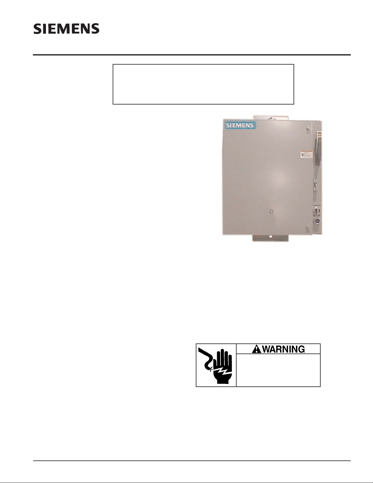
Description
Class 87 pump control panels include a Class 14 magnetic
starter with either a circuit breaker or a fusible disconnect
switch, a START push button and a HAND-STOP-AUTO selector
switch. These components are mounted in a NEMA 3R weather resistant enclosure with a gasketed door that can be easily
removed. Sizes 1 through 4 are furnished with a watertight conduit hub on top and conduit knockouts on the bottom.
The Class 87 pump control panel can be supplied with either
Class 10 ESP100 quick trip solid state overload or a ambient
temperature compensated bimetal overload.
Enclosures for Sizes 1 through 4 are furnished with pole mounting brackets: Size 5 with floor mounting legs. Size 6 is base
mounted.
Pump panel optional accessories include back-spin timers, lightning arresters, control transformers, auxiliary interlocks, pilot
lights, fuse clip kits and undervoltage relays.
Installation
1. Examine each device on the panel for shipping damage and
if any is noted, notify carrier for claim. Do not apply power
to any damaged device.
2. Operate disconnect switch or circuit breaker with external
handle to verify operation.
3. Manually operate magnetic starter to determine that moving
parts do not bind.
4. Check horsepower and current rating of motor or other load
with pump control panel rating.
5. Install in conformance with National Electric Code and any
applicable local electric codes. Install the proper size dual
element fuses in the disconnect switch (fuses are not supplied as part of pump control panels).
6. Firmly fasten enclosure to solid mounting surface.
7. Install conduits and necessary grounding means and wire
pump control panel in accordance with the wiring diagram
supplied. Joint compound or the equivalent is recommended on conduit threads to prevent water from entering pump
control panel. If top conduit hub is not used, be sure to plug
it securely to prevent entrance of water.
8. Check that all wiring is secure and does not interfere with
proper operation of any devices.
9. Check that all wiring connections are tight, including factory
connections.
10. Refer to the heater table on the door of the enclosure and
install the proper overload heaters for the specific motor
being controlled (heaters are not supplied as part of pump
control panels).
11. Make a final installation check of steps 1 through 10 and
remove any foreign material from the enclosure.
12. Close and latch door before applying power.
13. Apply power by placing the disconnect handle in the ON
position.
14. Rotate selector switch to HAND position and depress
START button.
15. Check for proper pump motor rotation. Motor rotation can
be reversed by interchanging any two (motor) leads at the
starter load connections.
General Maintenance
In many applications, the magnetic control can be expected to
be trouble free during the entire operating life of the pump.
Routine inspection and maintenance as follows will help to
insure this.
1. Periodically clean the inside of the enclosure by blowing out
dust, etc. which may have accumulated.
Hazardous voltage.
Can cause death, serious personal
injury, or property damage.
Disconnect power before working on
this equipment.
(For Engineering Reference Only - Rev. E)
IMPORTANT
THESE INSTRUCTIONS DO NOT PURPORT TO COVER ALL DETAILS OR VARIATIONS IN EQUIPMENT, NOR TO PROVIDE FOR EVERY POSSIBLE
CONTINGENCY TO BE MET IN CONNECTION WITH INSTALLATION, OPERATION OR MAINTENANCE. SHOULD FURTHER INFORMATION BE
DESIRED OR SHOULD PARTICULAR PROBLEMS ARISE WHICH ARE NOT COVERED SUFFICIENTLY FOR THE PURCHASER’S PURPOSES,THE
MATTER SHOULD BE REFERRED TO THE LOCAL SIEMENS SALES OFFICE.
THE CONTENTS OF THIS INSTRUCTION MANUAL SHALL NOT BECOME PARTOF OR MODIFY ANY PRIOR OR EXISTING AGREEMENT, COMMITMENT OR RELATIONSHIP. THE SALES CONTRACT CONTAINS THE ENTIRE OBLIGATION OF SIEMENS. THE WARRANTY CONTAINED IN
THE CONTRACT BETWEEN THE PARTIES IS THE SOLE WARRANTY OF SIEMENS. ANY STATEMENTS CONTAINED HEREIN DO NOT CREATE
NEW WARRANTIES OR MODIFY THE EXISTING WARRANTY.
For replacement parts information or an application guide, visit
our website at www.sea.siemens.com or contact your local
Siemens sales office.
Page 2
87-HFG
Page 2
May, 2002
Supersedes April, 2002
Instructions
Siemens Energy & Automation, Inc. 1000 McKee Street Batavia, Illinois 60510
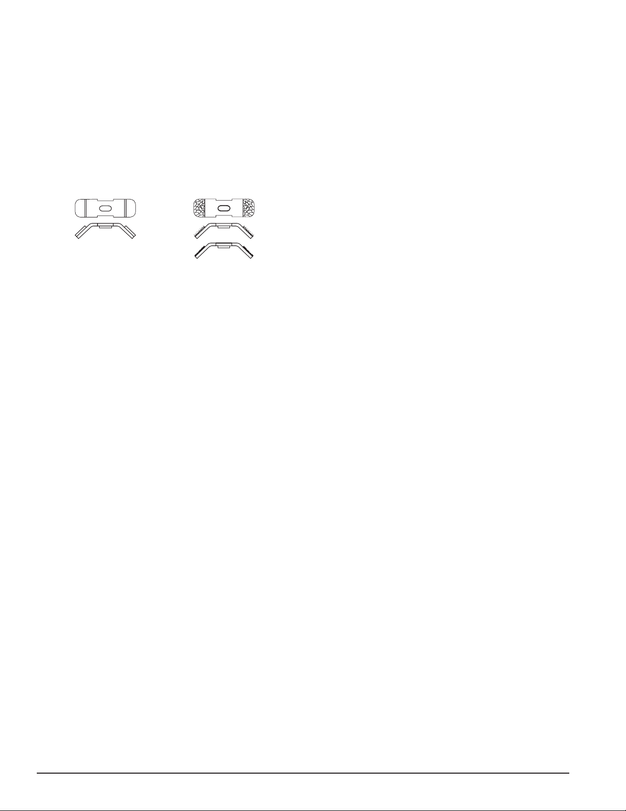
2. Periodically examine the contacts - cleaning is not required
since the contact material is a special preoxidized silver cadmium oxide alloy. Replacement is required only when the
contact material is almost worn down to the backing. A
complete pole consists of stationary and movable contacts
and a contact spring. This feature insures proper contact
mating which, in turn, provides maximum life.
3. Check magnet poles for foreign deposits and if present,
carefully clean pole faces with solvent.
4. Check all screws for tightness.
5. Depress test-trip button on overload relay and then reset
overload relay. This insures the relay’s ability to open the
control circuit if necessary.
 Loading...