

Page 1
Local Service Organization Service Manual
BE INSPIRED
SIEMENS COMMUNICATIONS LIMITED
Our innovation shapes the future
Page 2

Table of Content
CHAPTER 1
Cellular Communication
Coverage Concept 1
GSM Network Architecture 2
Subscriber Identity Module 3
SIM Application Toolkit 4
Extended GSM 900 - EGSM 4
WAP 5
CHAPTER 2
Level 2 Service Guide 6
Introduction 6
General Information 6
CL50 Series Technical Information 7
Accessories 10
CL50 Mechanical Diagram 11
Mechanical Concept 12
Hardware Concept – Block diagram 13
Hardware Description 13
Power Supply Concept 15
Battery Charging 16
CL50 Spare Parts Level 1 & Level 2 19
Disassemble the CL50 20
Assemble the CL50 24
Mobile Software Programming 30
Language Groups 34
Customer Specific Initialization 34
International Mobile Equipment Identity 34
i
Page 3
Ch
r
apte
Cellular Communication
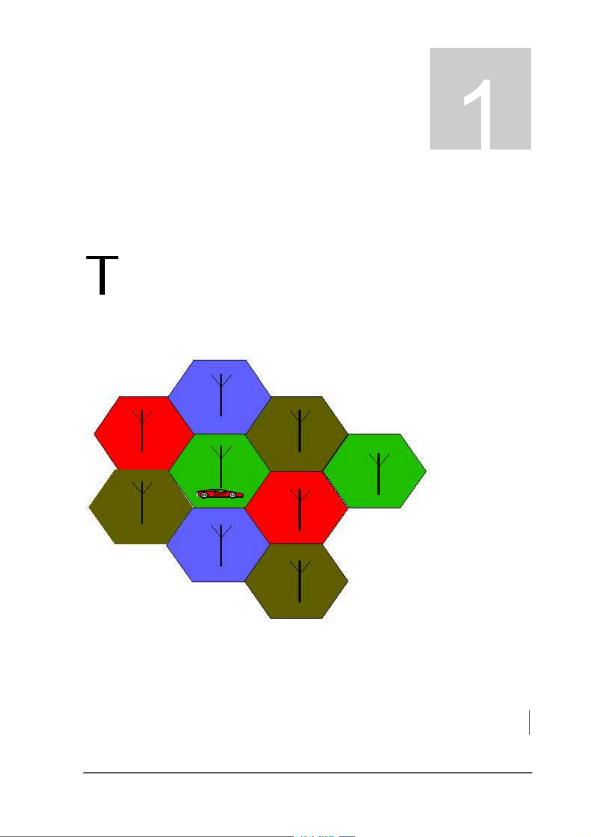
Coverage Concept.
he cellular systems is made up of numerous transmitting and receiving sites, whose
individual coverage areas partially overlap. The concept of frequency re-use, same
frequency is used by several sites, allows a high traffic density in a wide area. Due to the
limited transmission range of the terminals, cellular systems are based on a large
number of base stations on the infrastructure side, scattered over the area to cover, with each
covering a fairly small geographical zone called cell. Cells are often represented by hexagons
(see figure 1.1.).
FIGURE 1.1 CELLULAR COVERAGE REPRESENTATION.
1
Page 4
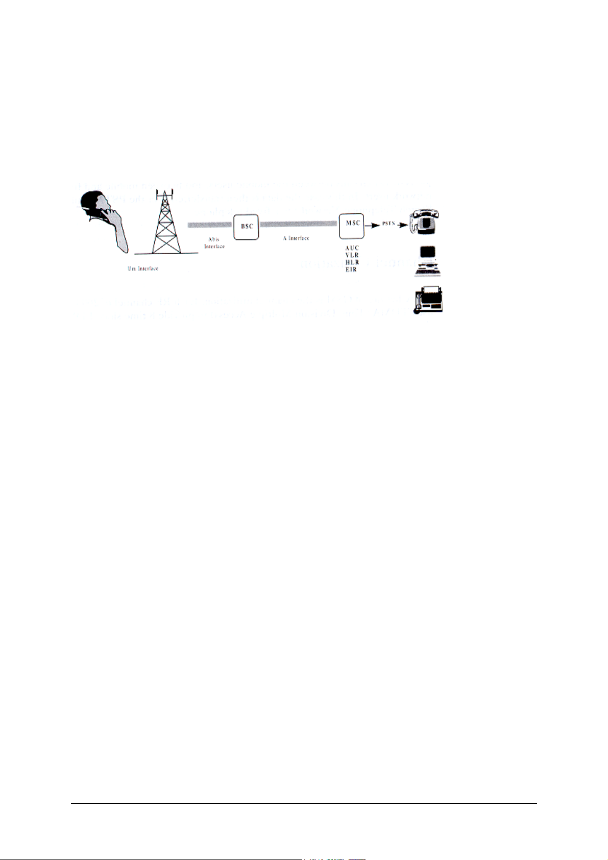
GSM Network Architecture.
GSM network can be broadly divided into three broad parts, namely:
1. Mobile Station(MS) carried by the subscriber,
2. Base Station Sub-system(BSS) which controls the radio link with the mobile station.
3. Mobile Switching Center(MSC) which performs the switching of calls between the mobile
users, and between mobile and fixed network users.
FIGURE 1.2 GSM ARCHITECTURE
Each mobile station is given a unique identity. As soon as the mobile phone is turned on, it
registers with the network and is authenticated; as such the network could always find the mobile
phone.
Larger amount of data is being exchanged to and from the following functional blocks in the MSC:
Visitor Location Register, VLR
Stores information about mobile subscribers that enter it coverage area, which is associated with
the geographical area where the mobile is currently roaming. When there is an incoming call for
the mobile, the HLR is interrogated about the present address of the VLR.
Home Location Register, HLR
A database that contains all data concerning the subscription of the mobile subscriber, i.e. their
access capabilities, subscribed services, and supplementary services. It also contains information
about the VLR that is handling the mobile station currently. When the mobile changes location,
the HLR is updated accordingly. It also provides the MSC with information about the MSC area
where the mobile is actually located to allow incoming calls to be routed immediately to the called
party.
Authentication Center, AUC
Stored information that is necessary to protect communication through the air interface against
any intrusions. The legitimacy of the subscriber is established through authentication and
ciphering, which protects the user information against unwanted disclosure.
Equipment Identity Register, EIR
An option the network operator can use to enforce security. With this feature the network can
identify defective or stolen mobile that may not be used in the network.
2
Page 5
Subscriber Identity Module (SIM)
SIM is a smart card, which has a computer, and memory chip that is permanently installed in the
mobile equipment. It comes in either the size of a credit card or smaller version known as the
plug-in SIM.
The subscriber information, which includes a unique number called the International Mobile
Subscriber Identity (IMSI) is stored in the SIM card. SIM card identifies the subscriber to the
network.
To protect the SIM card from improper use, a security feature, a four digits personal identification
number (PIN), is built in. The PIN is stored in the SIM card and can be changed by the
subscriber. PIN2 is required for additional functions available with a special SIM card (Consult the
operator for more information about the PIN 2).
A code (PUK) is provided for unlocking the SIM card if the SIM card is blocked
.
3
Page 6

SIM Application Toolkit
This is a new GSM feature that has been integrated into the GSM standards in Release 96, with
further enhancements added as part of the Release 97 feature set. This feature came about
because of a desire by Network Operators to offer differentiated services, without the need for the
Mobile Manufacturers having to build different variant for different customers. The unique service
offered by the Operator is placed as an application on the SIM and that could work on any mobile
that supports the Toolkit feature.
There is a distinct set of commands between the mobile and the SIM specifically for the Toolkit
that allows the SIM Toolkit and the mobile to communicate independently of the GSM
communication between the SIM and the mobile. Henceforth, the SIM Application Toolkit and
GSM functionality on the SIM are separated logically. The Toolkit can interact directly with the
mobile itself and adding itself to the mobile menu.
Currently, Toolkit application on the SIM and its “other half” communicate by using the Short
Message Service(SMS). “Proactive SIM” is a mechanism whereby the SIM can initiate actions to
be taken by the mobile. These actions include:
· Display text from the SIM on the Mobile display
· Send short message
· Set up a voice call to a number held by the SIM
· Set up a data call to a number and bearer capabilities held by the SIM
· Send a Supplementary Service (SS) control or Unstructured Supplementary Services Data
(USSD) string
· Play a tone in the mobile’s ear piece or ringer
· Initiate a dialogue with the user
· Provide local information from the mobile to the SIM.
· Data download to the SIM from network
· Call control by the SIM.
SIM Applications Toolkit (SAT) allows the flexibility to update the SIM, to change the services and
download new services over the air. In the SAT specification, the short message service is a key
mechanism for personalizing the SIM in each user’s GSM phone. It is designed as a client-server
application. CL50 supports SAT Class 3 specification.
When active, the name of the service may appear in the menu, and there will be sub-menu if
more than one application is active. Figure 1.4 is the SAT icon.
FIGURE 1.4 SAT ICON
Extended GSM 900, E-GSM
This is a new standard that allows Network Operators to increase their capacity through an
extended frequency. The frequency range of E-GSM is as follows:
· Mobile Transmit: 880 – 915 MHz
· Mobile Receive: 925 – 960 MHz
CL50/8008 series is a GSM Phase 2 / Phase 2+ Dualband E-GSM / GSM 1800 mobile phone.
4
Page 7
Wireless Application Protocol, WAP.
Wireless Application Protocol takes a client-server approach that uses the in-built micro-browser
to make a request, in wireless markup language (WML), for information or service. The request is
passed to a WAP Gateway, which then retrieves the information from a Internet server, in HTML
format, and translate it into WML. The requested information is then sent to from the WAP
Gateway to WAP client (mobile) using the available and most appropriate mobile network bearer
services.
Wireless Protocol Stack.
Wireless Application Environment (WAE)
Wireless Session Protocol (WSP)
Wireless Transaction Protocol (WTP)
Wireless Transport Layer Security (WTLS)
Wireless Datagram Protocol (WDP)
Bearers e.g. Data, SMS, USSD
TABLE 1..1 WAP PROTOCOL STACK
1. Wireless Application Environment
Defines the user interface on the phone. WAE contains the WML,WML script and the
wireless telephony application (WTA).
2. Wireless Session Protocol
Link the WAE to two session services – one connection oriented operating above the WTP
and a connectionless service operating above WDP.
3. Wireless Transaction Protocol
Runs on top of the datagram service and part of the standard suite of TCP/IP protocols, to
provide a simplified protocol suitable for low bandwidth mobile station.
4. Wireless Transport Layer Security
WTLS incorporates security features that are based upon the established Transport layer
Security (TLS) protocol standard, that include data integrity checks, privacy on the WAP
Gateway to client leg and authentication.
5. Wireless Datagram Protocol
Allows WAP to be bearer independent by adapting the transport layer of the under-laying
bearer. WDP presents a consistent data format to the higher layer on the WAP stack.
WAP Internet access via the CL50 is possible with the inclusion of Wireless Application Protocol
(WAP) browser 1.2.1.
5
Page 8

Ch
r
apte
Level 2 Service Guide
Introduction
The chapter is intended to help you carry out repair up to Level 2 on the CL50 series mobile
phone.
General Information
CL50 is a dual band (GSM 900 and GSM 1800) Siemens GSM clam shell.
Due to different requirements of the markets, the CL50 has different variants, which broadly
classified under International version and Asian version. Marketing name for international version
is CL50, whereas Asia version is 8008.
The CL50 and 8008 share the same phone accessories.
1
All repairs have to be carried out in an environment set up
according to ESD regulations defined in international standards.
ESD procedure is available from your Service Manager. Ask for
ASC/T001/98
6
Page 9
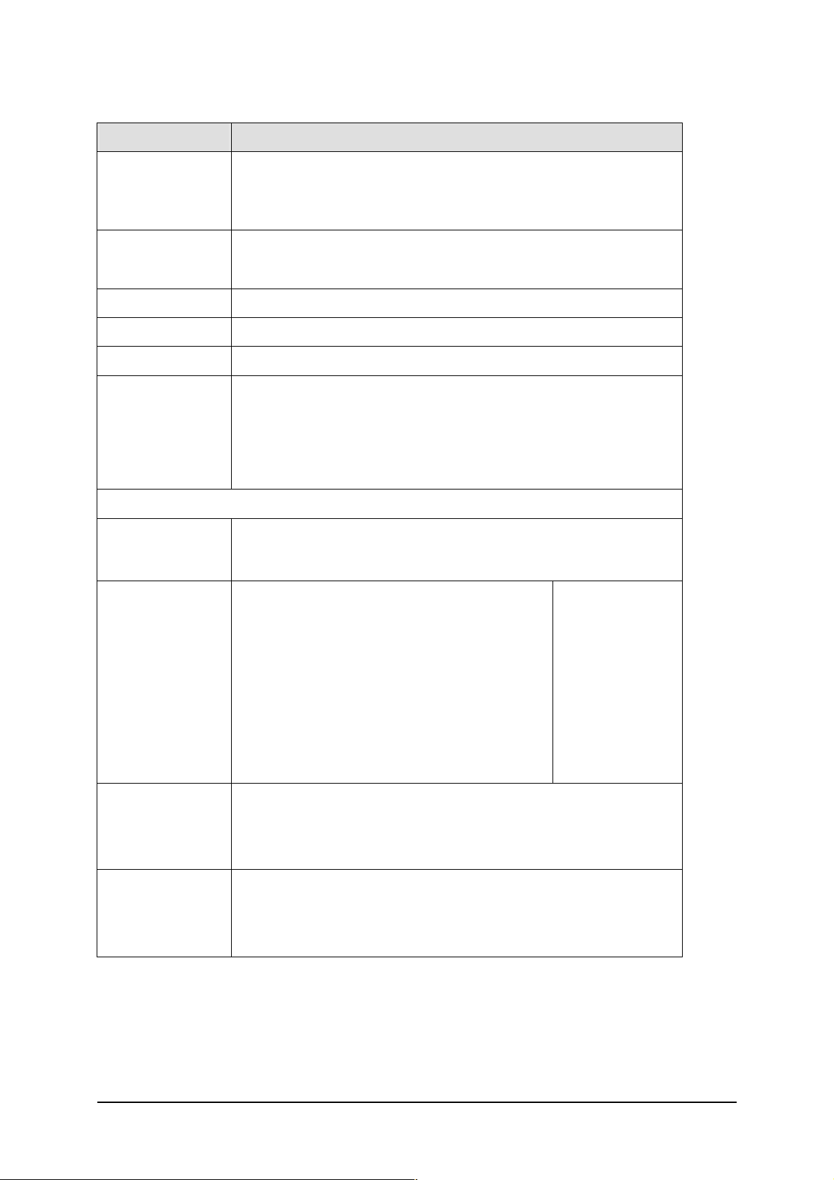
CL50 Technical Information
Spec. Desc.
· EGSM-900 (880MHz – 960MHz).
Frequency
Power
Antenna
WAP
Message
SIM Support
Display
Backlight
LED
· GSM-1800 (1710MHz – 1880MHz) also called DCS-
1800.
· EGSM-900: Power class 4
· GSM-1800: Power class 1
External Type
Version 5.0
SMS, EMS Support
· Plug in card 3V
· STK (SIM Application Tool Kit)
Class II & Class III Send USSD command
(Chinese supported)
· Internal & extermal LCD:Blue
· Keyset:Orange
· Red color is reserved for no network
service. It shall blink every 3 seconds
Internal LCD
External LCD
Status LED
· Green color is for:
· Network service available at idle mode.
It shall blink every 3 seconds
· Any call. It shall blink every 1 second
1. LED does not blink when call in
progress
· High Resolution Graphic
· 3 lines, 112 x 64 pixel
· 4 level Gray Scale
· High Resolution Graphic
· 1 lines, 96 x16 pixel
· 4 level Gray Scale
5mm x 1mm
status LED light
will be placed on
the top of the
housing, near the
antenna
7
Page 10
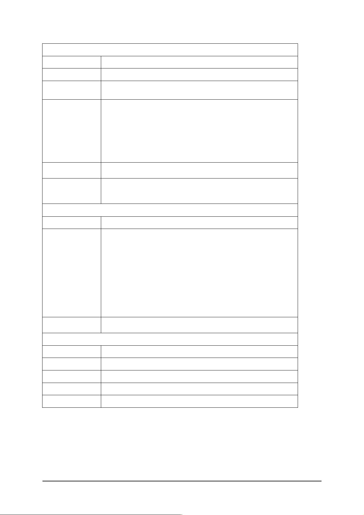
Physical Details
Dimension 73mm(L) x 39mm(W) x 22mm(D)
Volume 53 cc (approx)
Weight 80g (approx)
· 2 side keys
· 2 function keys (Send, Power / End)
Keypad
Decorate Hook
Temperature
Range
Power
Battery
Consumption
· 2 multifunctional softkeys
· 4-Way Navigation keys
· 12 numeric keys (10 numeric,*, #)
There must be a hook hole in the housing so that consumer can tie
a string to it for hanging the phone around the neck.
· -10 oC to +55 oC for normal operating
· -40 oC to +85 oC for storage
600 mAh Li-ion Battery
· Min stand-by time 220 hrs(*)
· Min talk time Best Case (DTX off, GSM900, PL19) = 3.8
hrs(*)
· Min talk time Best Case (DTX on 40%, GSM900, PL19)
= 4.5 hrs(*)
· Based on Siemens measurement method and
procedures
(*): Actual time depends on the network
Charging
Maximum charge time for empty battery (0-5% capacity) is 2 hours
for standard charger and via battery charging station
Audio
Ringer On/Off/Beep
Melody 20 embedded + 10 download + 3 compose
Melody Type YAMAHA SMAF MA1
Key tones Click/Tone/Silent
Info tones On/Off/Extended
8
Page 11

Speaker Volume Adjustable in 4 levels during call via volume keys
Silent Alert Built-in vibrator
Setting
User profiles Normal/Quiet/Noisy/Headset/Aeroplane mode/2 Empty
Group Friends/Colleague/Family/Biz Partner/VIP
Wallpaper 3 default + 2 customized + OFF
Answer Mode Any key/Key Tones/Flap
Security Codes/Only >FDN> (Operator support)/This SIM only
Other Feature:
ü Up to 50 coming/sending messages can backup from SIM card to CL50.
ü Up to 100 records can be saved on CL50.
ü Calling melody by group or person (2
ü Own greeting text
ü Intelligent Typing (T9)+Libraries
ü Two city clock
ü Alarm/Date
ü Diary
ü Mobile Internet Access
ü SMS to group
nd
priority, only apply to address book)
9
Page 12

Accessories:
Accessories
1BC9ZZZFX01 Standard Charger
1BC9ZZZFX19 Battery only Charger
1BTCZZZFX05 Battery, Li (3.7V, 600mAh)
Note:
Item highlighted in italic is Quanta Part number for Siemens.
10
Page 13

CL50 Series Mechanical Diagram
FIGURE 2.1 CL50 MECHANICAL DIAGRAM.
11
Page 14

Mechanical Concept
Please take note that the number(s) used here IS NOT the part
number, DO NOT used it in your spare parts purchase order.
Always refer to the SERVICE PART PRICE LIST
for your spare part order.
The mechanical concept of the CL50 as a clam shell is much different from other Siemens series
mobile phones.
CL50 can be divided into two main physical blocks, the display module and main function assy.
The display module is composed of internal and external LCD protected by LCD base and lens
with shielding effect. The display module will joint buzzer, receiver and top cover as LCD module
and the housing will damaged if striping the module down.
For the main function assy., there are 4 screws located on the base and 1 on the M/B.
Screwdriver (T5) and tweezers will be used as main tools to perform mechanical repair.
Inside, the CL50 consist a M/B, which carries control and RF section of the mobile, and a key
PCB and microphone directly insert into plug-in connectors to show function. The display module
and vibrator are connected to the board by the flexible cable which is inserted into a plug-in
connector. In case they are defective electrically or mechanically it can be exchanged very
quickly. DC jack cover, volume key knob and key cover can be easily taken off as well. Speaker
also can be separated from base. Make sure the speaker springs are not dirty or damaged during
repair process.
The contact points of software upgrading and connector for external RF cable are located at the
back side of the mobile. As a consequence of this, there needs a extra jig which can put in the
battery or connect to power supply after modification to perform the download and test process.
The CL50 is a dual-band mobile operating on GSM900 and
GSM1800, the antenna is an integral part of the base.
12
Page 15

Hardware Concept – Block Diagram
FIGURE 2.2 CL50 BLOCK DIAGRAM.
Digital Baseband Processor (AD6522)
The AD6522 is the central element of a new advanced, very low power GSM solution, the
AD20msp430 chip set. It can be divided into three main subsystem: Control processor
subsystem, DSP subsystem, Peripheral Function.
Interface
Universal
System Conn.
Test
SIM
DSP
ü Channel Codec
ü Channel Equalizer
ü Speech Codec
SYSTEM SRAM
Interface
Voiceband/
Baseband Codec
Display
Radio
Data
Memory
Control Processor
MCU
Accessory
Keypad/Backlight
13
Page 16

TRANSCEIVER ( CX74017 )
The receive path implements a direct down-conversion architecture that eliminates the
need for Intermediate Frequency (IF) components. The CX74017 receiver consists of
three integrated Low Noise Amplifiers (LNAs), a quadrature demodulator, tunable
receiver baseband filters, and a DC-offset correction sequencer. In the transmit path, the
device consists of an In-phase and Quadrature (I/Q) modulator within a frequency
translation loop designed to perform frequency up-conversion with high output spectral
purity. This loop also contains a phase-frequency detector, charge pump, mixer,
programmable dividers, and high power transmit Voltage Controlled Oscillators (VCOs)
with no external tank required. Except for the loop filter, the frequency synthesizer
function, including a wideband VCO, is completely on-chip.The radio frequency gain
range of GSM=20dB, DCS/PCS=22dB and baseband gain range.
VOICEBAND BASEBAND CODEC ( AD6521 )
It contains complete codecs for the conversion of voiceband signals as well as D/A-converter to
control the radio subsystem and an auxiliary A/D- converter for system monitoring purposes. The
baseband codec is a complete low power, two channel, input/output port with signal conditioning.
The transmit path consists of a GMSK modulator and two high speed DACs with output
reconstruction filters together with a ramp DAC with on-chip RAM providing the power ramp
shape. The receive path consists of two high-resolution Sigma-Delta A/D converters which
include high performance digital filters for RF-channel selection.
The voiceband codec is a complete analog front-end, which can interface directly with a
microphone and speaker. For interfacing with hand-free or external car kits, separate input and
output channels are provided.
The auxiliary section consists of D/A converters for Automatic Frequency Control (AFC) and a
current DAC (IDAC) for battery charging applications. Additionally, an auxiliary A/D converter in
included, which can be used to monitor up to six analog signals.
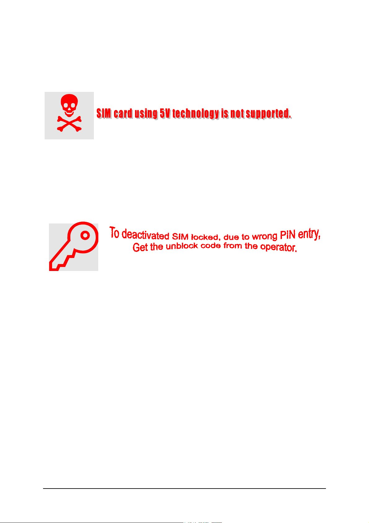
The telephone support only 1.8V and 3V SIM card
For user with 5V SIM card, he needs to upgrade the SIM card
through his service provider/network operator
14
Page 17

Power Supply Concept
The CL50 has two main power inputs:
1. Battery voltage (3.7V) connected at the battery contact
2. Charging voltage (5V) delivered by the different charger type(see Accessory List) via
DC jack at the bottom of the telephone.
Since the battery voltage is supplying the power supply ASIC, it is always needed to
operate the phone. You cannot switch on the handset if the battery voltage is not
present.
From the battery voltage, all other supply voltages are derived and controlled by the
power supply IC.
The RF power amplifier is directly connect to the battery, a bad battery with high internal
resistance can cause malfunction of the CL50 phone.
Charger(5V/400 mA)
Charging
Circuit
Power Amplifier
The IC generates the supply voltage to other as below:
SIM Card: 2.80-2.92 V/ 20mA
RTC: 2.40-2.50 V/10uA
Memory: 2.744-2.865V /60mA
Digital Core: 2.40-2.50 V/ 100mA
Analog: 2.40-2.50V/ 130mA
TCXO: 2.744-2.865V /60mA
The IC also checks the presence of the watchdog signal from the microprocessor and
provides the switching on functionality (ON_OFF button or Ignition signal).
Wrong polarity or battery voltage setting that exceed the +6.2V could
damage the phone.
15
Page 18

Over-voltage Condition
· Battery voltage
If the supply voltage rises above 6.2V, the phone will switch off and it cannot be
switched on again before the voltage is lower than 6.2V.
If the supply voltage rises above 10V, the phone can be damaged.
· Charging Current
The charging current must not rise above 1A or a track fuse in the phone will blow. As
a result charging the battery will no longer by possible.
Be careful with NON-original SIEMENS accessories or chargers.
Make sure that the charging current is limited to value below 1A.
Battery – Charging
CL50 series uses a Li 600mAH battery pack as standard battery and the supplier is
“Sanyo”.
Contact points
16
Page 19

Batt+ Batt_Temp GND
For CL50, BATT+ has a voltage level from +3.4V to 4.2V, and a BATT_TEMP contact is used for
detecting abnormal increase in temperature of the battery.
If the temperature is too high or too low, there is a high probability
that the battery is not charged. To enable the charging process
again, battery and phone needs to cools down or warm up. Battery
replacement is not required.
Avoid shorting the battery terminals.
Short Circuit Protection
For the Nickel Metal Hydride battery, a polyswitch in the battery pack protecting the battery from
short circuit and it should reset by itself after some time removing the short circuit.
For the Lithium Ion battery, it is short-circuit protected by an electronics fuse. The fuse will be
activated in case a too high current is drawn. This fuse will not reset automatically.
The resetting of the battery fuse can be done with either of the following procedures:
1. Insert the battery into the CL50 and then connect the rapid charger to the phone. Wait for
approximately 10 second, then the mobile can be turned on again.
2. Plug the battery separately into the desktop charger. The fuse is reset immediately.
Charging
The battery can be charged when it is inserted into the phone. The charging process is
completely controlled by the mobile. Charging can be done with any of the following accessory:
1. Rapid charger
2. Travel charger
17
Page 20

PHOTO 2.4 INSERT CHARGER
Please make sure the triangle mark faces down.
Deep Discharge Battery
In case of a deeply discharged battery, the voltage of the battery is too low to operate the
charging circuit and the display controller, the phone cannot be turned on and the normal
charging process cannot be started. No charging symbol is visible in the display.
In this case, charging the battery is divided into two different steps, which have to be run
subsequently:
a) Trickle charge for CL50 Phone
Trickle charge mode is automatically started if the battery voltage is below 3.0V when the
charger is connected to the mobile. The charging current in Trickle mode is appr. 10mA.
Action:
Insert battery into handset and connect travel charger to the telephone. The charging
symbol will not show in the display.
b) Normal charge
When the battery voltage is above the a.m. value (e.g. by trickle charge) the mobile will
start the normal charging mode and show a charging symbol in the display. * Always
normal charge a new battery or a deep discharged battery for more then 12 hours before
first use.
Action:
Connect charger to the telephone (see section on Charging).
The charging symbol will come up as an indication that the normal charging process has been
started by the mobile.
18
Page 21

Mobile Phone M50 Spare Parts Level 1 and Level 2 / 2.5
Swap Unit
1HYCZZZFX10 Swap units, transceiver device only
Spare Parts Level 0
1MIZZZZFX44 Battery Cover Assy.
L36197-F5012-F624 DC Jack Cover
Spare Parts Level 1
L36197-F5012-F629 LCD Module, LCD assy and Top Cover
Base Assy
L36197-F5012-F625 Keys
L36197-F5012-F627 Key Pad PCB Assy
L36197-F5012-F626 Key Cover
L36197-F5012-F628 Rubber Key Frame
L36197-F5012-F630 Microphone (including rubber)
L36197-F5012-F631 Speaker
L36197-F5012-F632 Vibration Motor (including rubber)
L36197-F5012-F633 Volume Key Knob
L36197-F5012-F634 Poron Key1
L36197-F5012-F635 Poron Key2
L36197-F5012-F636 Poron Key3
L36197-F5012-F607 Shielding cover (baseband)
L36197-F5012-F623 Shielding Cover (RF)
L36197-F5012-F608 Screw l 5.0
L36197-F5012-F609 Screw II 4.0
Spare Parts Level 2
19MBZZZFXH5 M/B PCBA Assy.
Spare Parts Level 2,5
L36197-F5012-F610 RTC Battery
L36197-F5012-F611 LCD Connector
L36197-F5012-F612 MIC Connector
L36197-F5012-F613 SIM Connector
L36197-F5012-F614 Vibrator Connector
L36197-F5012-F615 Battery Connector
L36197-F5012-F616 Key Pad Connector
L36197-F5012-F617 DC Jack
L36197-F5012-F618 Phone Jack
L36197-F5012-F619 Speaker Spring
L36197-F5012-F620 Status LED
L36197-F5012-F621 Hall IC
Documentation and Software
L36008-H6900-A1 User Guide UG1 8008 english
L36008-H6900-A2 User Guide UG2 8008 chinese simpl.
L36008-H6900-A3 User Guide UG3 8008 chinese trad.
L36008-H6900-A4 User Guide UG4 CL50 english
Note:
Item highlighted in italic is Quanta Part number for Siemens.
19
Page 22

Disassembly / Reassembly Instruction
The equipment described in this manual contains electrostatic devices
(ESDs). Damage can occur to these devices as well as components if the
appropriate handling procedure is not adhered to. The operation area
should be equipped with well protection to these components and devices.
Disassemble of the CL50
Tool: Electrical/Normal Screwdriver(T5), Tweezers
Notice: Torque (M1.6*5, blue): 0.5 ± 0.01 Kgf/cm
Torque (M1.6*4, red): 0.4 ± 0.01 Kgf/cm
Step1: Remove battery cover and 4 screws located on base assy.
[2 blue(M1.6*5)+2 red(M1.6*4)]
Step2: Separate base assy. and watch out the LCD cable.
Remove DC jack cover, volume key knob.
20
Page 23

Step3: Use tweezers to take off LCD cable carefully.
Make LCD module separate from M/B.
Step4: Remove key PCB
Step5: Open phone jack cover.
Step6: Remove the screw located on M/B.
21
Page 24

Step7: Lift up the M/B from end side.
[1 red (M1.6*4)]
Step8: Draw out vibrator and MIC pins carefully.
Step10: Remove shielding cover & pronos.
22
Page 25

Step11: Gently apply pressure under speaker down side and take out form base assy.
Step12: Separate LCD module and remove keys& key cover.
23
Page 26

Assemble of the CL50
Step1: Combine LCD module, put key cover& keys on.
Step2:Align the position and push the speaker into the hole of base.
Step3: Put shielding covers on and stick 3 pronos on.
24
Page 27

Step4: Align the rubber position and insert the MIC into M/B.
Step5: Align the position and insert the vibrator into M/B.
Step6: Slide M/B into base from front end and press the both rear side ends. Make M/B fix in the
fillister.
Step7: Tighten the screw located on M/B
25
Page 28

Step8: Combine M/B and key PCB.
[1 red(M1.6*4), red ]
Step9: Combine M/B and LCD Module
Step10: Put DC jack cover on.
26
Page 29

Step11: Put volume key knob in the side fillister.
Step12:Apply pressure on top and base to assemble all parts toghter.
Step13: Tighten the 4 screws located on base assy.
27
Page 30

[2 blue(M1.6*5)+2 red(M1.6*4)]
28
Page 31

Complete Disassembly Diagram
Complete Assembly Diagram
29
Page 32

Mobile Software Programming
Mobile Software Updating
PC
Handset
D/L Jig
RS232 Port
Battery
The software of CL50 is loaded from a PC directly. Hardware interconnection between the mobile
and the PC and D/L jig are shown above.
D/L Jig (Part Number:N/A):
30
Page 33

SW Download Process
1. Install the Service SW into PC just double click ”Setup.exe” in the folder and follow
instructions in process.
2. Launch the application while ready for connecting to handset as above. Check the file name
in the release row, which indicates the current version.
31
Page 34

3. Press the power-on key on the phone until release message is shown. The download
process will start and takes about 6~10 minutes.
32
Page 35

4. After download process is completed, remove the handset. Chose “Reset” to reload and
press the on/off button to start download again.
5. To perform mapping, the software upgrading application must be closed before launching the
mapping application. Hardware connection remains the same. Select the required mapping
set from the pull-down menu.
33
Page 36

6. Press the power-on key on the phone until release message is shown. The download
process will start and takes about 30 seconds.
34
Page 37

7. After mapping process is completed, remove the handset and connect to another. Chose
“Reset” to reload and press the on/off button to start again.
35
Page 38

Customer Mode (*#369#)
In CL50, the repair technicians can dial *#369# on handset under normal operating condition to
check or adjust the below functions.
1. Contrast
2. Baseband test
n Illumination
n Buzzer
n Vibrator
n Keypads
n RTC status
n Microphone speaker test
3. Software version
4. Auto-answer
8. DTMF-on
9. Comport
SW version definition
The format of SW name shown on handset as below
: Adjust the LCD contrast
: Check the current software version
: Valid setup when insert test SIM
: Determine if DTMF function valid during calling.
: AT-DATA/GENIE, for RD analysis only.
(DateCode)n-(TTP Version)
(Project) (Customer) (RD Version)
DCW
Date Code : YYMMNN means the SW release date
TTP version : The internal version used for RD
Project : DG1 means Dinghy
Customer : MIC means Siemens
RD Version : The internal version used for RD
DCW : D means “Dual Band”; C means “Circuit Switch Mode”;
W means “Wap”
36
Page 39

Customer Specific Initialization
International Mobile Equipment Identify, IMEI
The mobile equipment is uniquely identified by the International Mobile Equipment Identity, IMEI,
which consists of 15 digits.
IMEI=TAC+FAC+SNR+SP
TAC: 6 digits, indicating type approved
FAC: 2 digits, indicating final assembly plant
SNR: 6 digits, indicating equipment serial number for manufacturer
SP:2 digits, spare
The part number for the CL50 is SXXXXX-SXXXX-AXXX where the last 4 letters specify the
housing and software variant.
CL50 series IMEI label is accessible by removing the battery.
Re-use of IMEI label is possible by using a hair-dryer to remove the IMEI label.
On this IMEI label, Siemens has also includes the date code for production or service, which
conforms to the industrial standard DIN EN 60062. The date code comprises if 2 characters: first
character denotes the Year and the second character denotes the Month. For example, the IMEI
above show date code M3.
Year Date Code Month Date Code
2001 M December D
.2002 N January 1
2003 O February 2
Table: DIN EN 60062 DATE CODE
Languague Groups
There are only 3 languages for the CL50 in total. These languages are divided into groups as
follows
Language groups Languages Tegic Languages
International
English, Simplified
Chinese, Traditional
Chinese
China English, Simplified
Chinese, Traditional
Chinese
Taiwan English, Simplified
Chinese, Traditional
Chinese
Singapore/Malaysia/HK English, Simplified
Chinese, Traditional
Chinese
Note: Tegic- T9 Input method support in for the languages BOLD.
TABLE 2.2 SOFTWARE LANGUAGE GROUPS.
37
English, Simplified
Chinese, Traditional
Chinese
English, Simplified
Chinese, Traditional
Chinese
English, Simplified
Chinese, Traditional
Chinese
English, Simplified
Chinese, Traditional
Chinese
Page 40

For detail information, contact your Service Manager
1
Disclaimer: This content is subjected to changes without notice.
Copyright ã 2002 Siemens Pte Ltd
ICM MP CCQ ASP/ASC Customer Care Service Center,
164, Kallang Way, #04-22, Kolam Ayer Industrial Estate, Singapore 349248
Author: Lee Kian Meng.
Phone +65-8454806 • Fax +65-8426641
First Print: Aug, 02
Revised Print: N.A.
Date Print: 28 Sep 2001
The reproduction and transmission of this document to unauthorized parties is not permitted without
written authority. Offender will be liable for any damages that may arise directly or indirectly through the
misuse of the document.
38
 Loading...