

Page 1
C62
LEVEL 2.5
REPAIR DOCUMENTATION
V 1.1
V1.1 Page 1 of 51 ICM CCQ GRM
Company Confidential
Level 2,5 C62 Copyright 2002 Siemens AG 10/2003
Page 2
TABLE OF CONTENTS:
INTRODUCTION..........................................................................................................................................3
1
2 IO-CONNECTOR.............................................................. FEHLER! TEXTMARKE NICHT DEFINIERT.
3 RTC BATTERY...........................................................................................................................................11
4 TRANSISTOR SOT-323 (FOR LEDS)......................................................................................................16
TRANSISTOR SOT-323 (FOR VIBRA) ...................................................................................................21
5
FUSE .............................................................................................................................................................26
6
7 VOLTAGE SUPRESSOR ............................................................................................................................31
8 TRANSISTOR SOT-223 ..............................................................................................................................36
9 ZENER DIODE.............................................................................................................................................41
10 LED COLOR YELLOW............................................................................................................................46
V1.1 Page 2 of 51 ICM CCQ GRM
Company Confidential
Level 2,5 C62 Copyright 2002 Siemens AG 10/2003
Page 3
1 Introduction
The C62 is a triple band (EGSM900/GSM1800/GSM1900) handportable phone with a Li-Ion
battery. There are three different colour variants. The colours are Eagle White, Pigeon Blue
and Cherry Red. For every colour, there are eight different keymat variants: Latin, Chinese
Stroke, Hebrew, Cyrillic, Thai, Bopomofo, Arabic and Greek.
Partnumber on IMEI label:
C62: S30880-S9230-Axxx,
where xxx may be any number from 100, 101, 102...
This manual is intended to help you carry out repairs on level 2.5, meaning limited
component repairs. Failure highlights are documented and should be repaired in the local
workshops.
It must be noted that all repairs have to be carried out in an environment set up according to
the ESD (Electrostatic Discharge Sensitive Devices) regulations defined in international
standards.
If you have any questions regarding the repair procedures or technical questions about the
spare parts do not hesitate to contact our technical support team in Kamp-Lintfort, Germany:
Tel.: +49 2842 95 666
Fax: +49 2842 95 4302
E-mail: st-support@siemens.com
V1.1 Page 3 of 51 ICM CCQ GRM
Company Confidential
Level 2,5 C62 Copyright 2002 Siemens AG 10/2003
Page 4

2 IO-Connector
2.1 Affected Units
2.1.1 Type: C62
2.1.2 Affected IMEIs / Date Codes: All / All
2.1.3 Affected SW-Versions: All
2.2 Fault Description
2.2.1 Fault Symptoms for customers:
Charging problems.
Problems with external loudspeaker or microphone
when using a car kit.
Problems with accessories connected at the system
connector.
Problems with SW booting.
2.2.2 Fault Symptom on GSM-Tester:
This fault cannot be detected with a GSM-Tester.
2.3 Priority:
........ Mandatory
⌧ ........ Repair
........ Optional
........ Not Yet Defined
2.4 Repair Documentation
2.4.1 Description of procedure:
V1.1 Page 4 of 51 ICM CCQ GRM
Company Confidential
Level 2,5 C62 Copyright 2002 Siemens AG 10/2003
Page 5
2.4.1.1 Diagnosis
Check the system connector visually. Watch for oxidation and dry
joints!
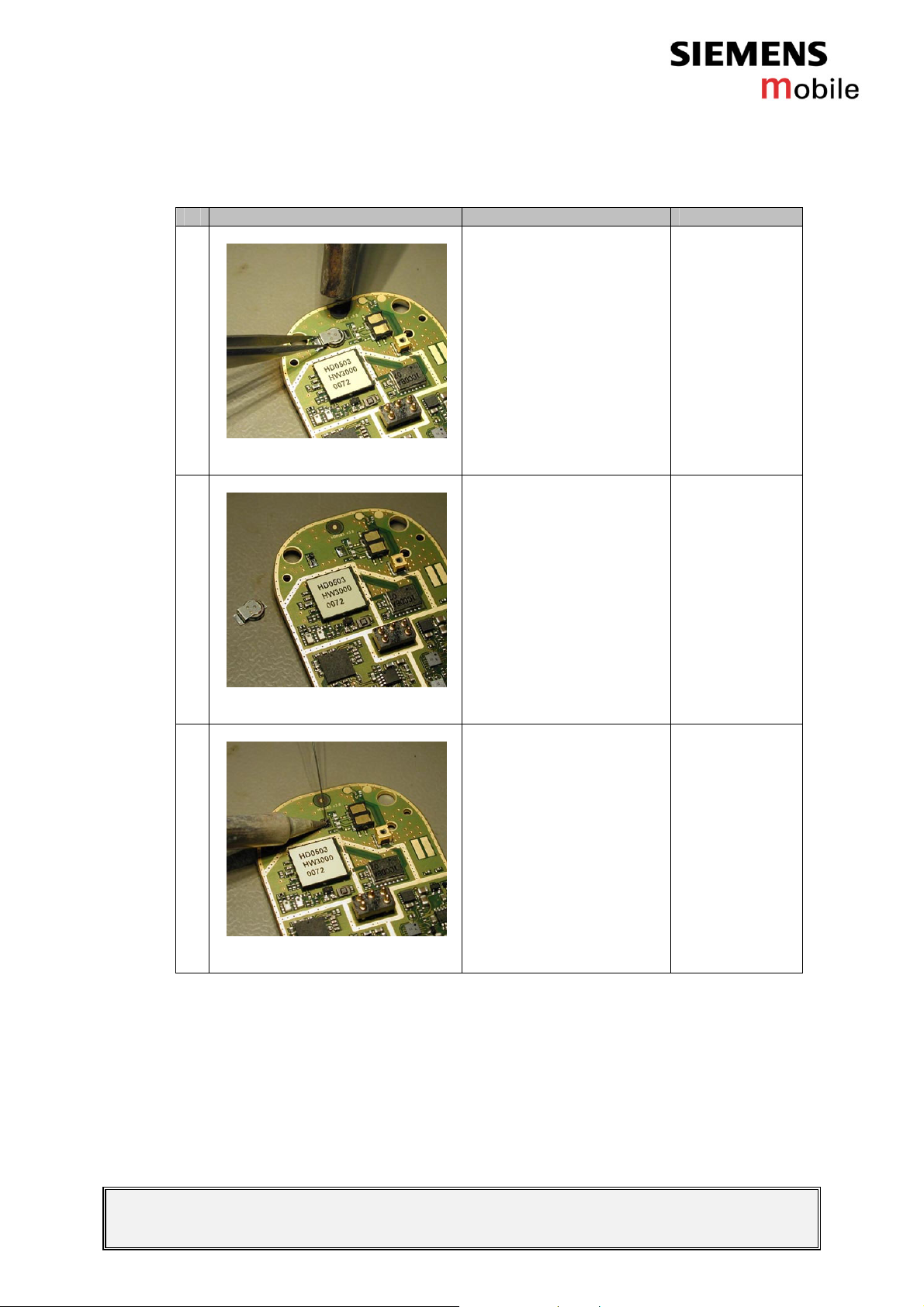
2.4.1.2 Repair by component change
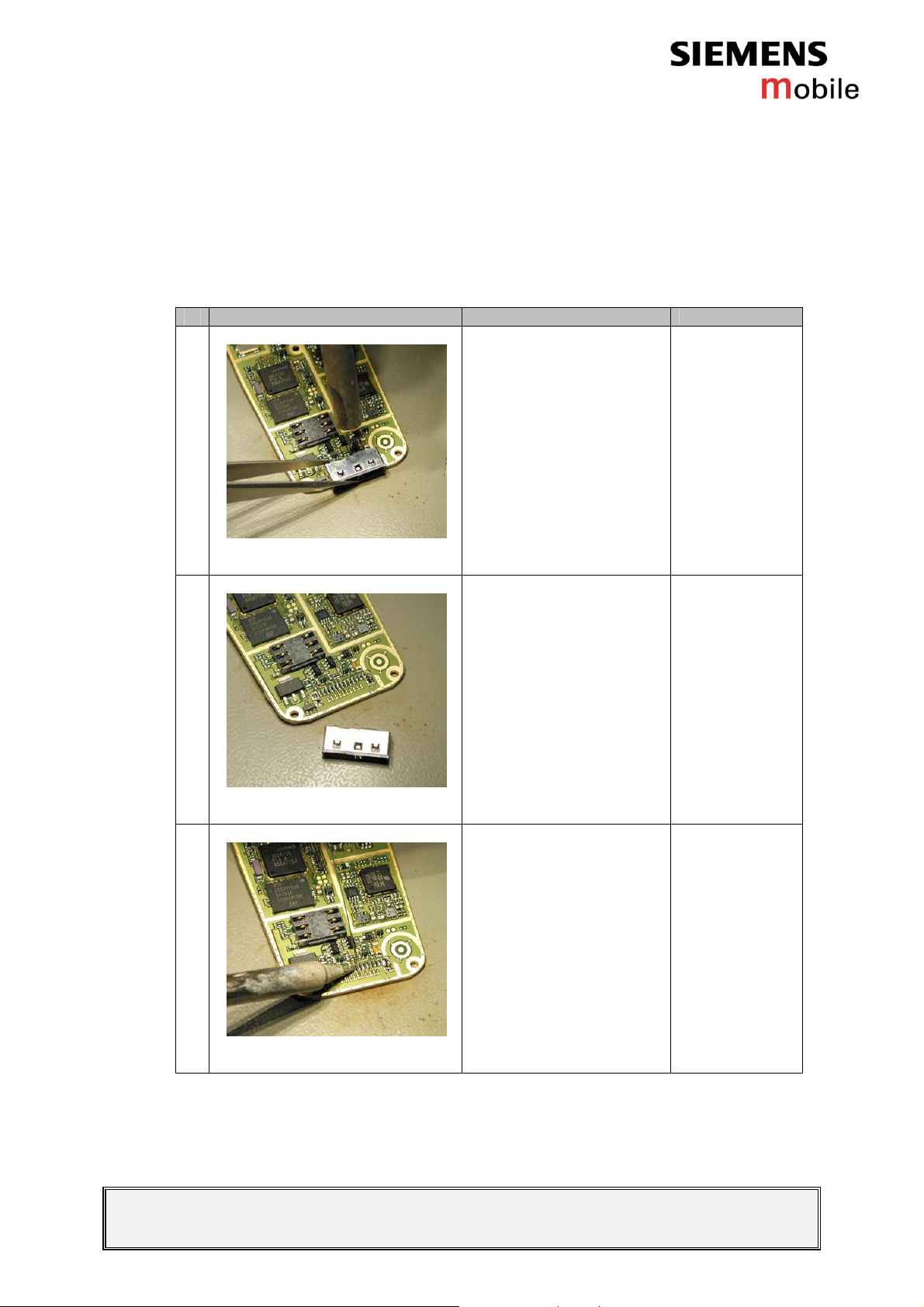
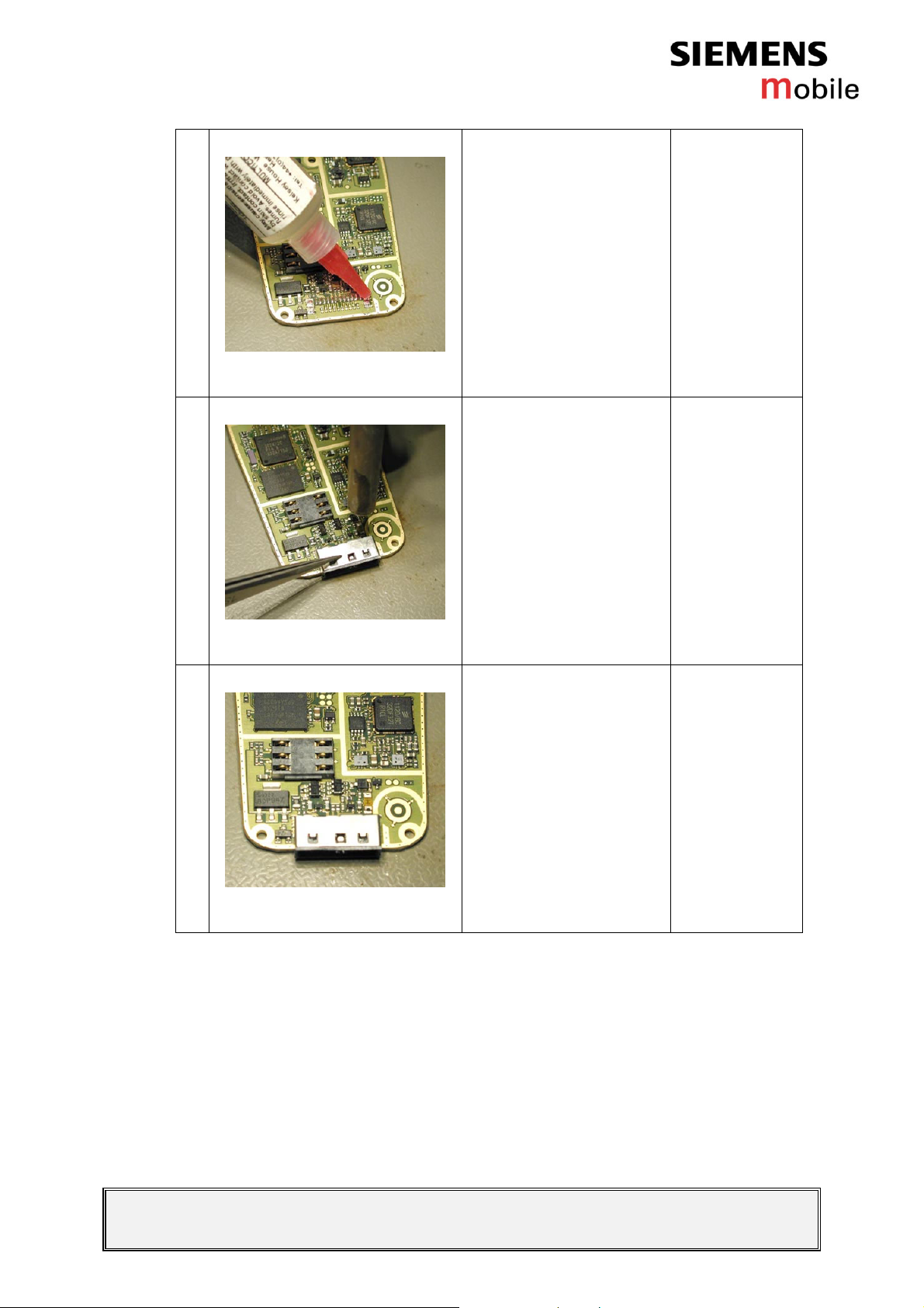
# Figure Instruction Note
1
Use a hot air blower to
remove the defective
system connector.
Avoid excessive heat!
Watch out for the
surrounding
components!!
Figure 2-1
2
Figure 2-2
3
Remove the defective
connecter.
Add solder on the pads.
Figure 2-3
V1.1 Page 5 of 51 ICM CCQ GRM
Company Confidential
Level 2,5 C62 Copyright 2002 Siemens AG 10/2003
Page 6
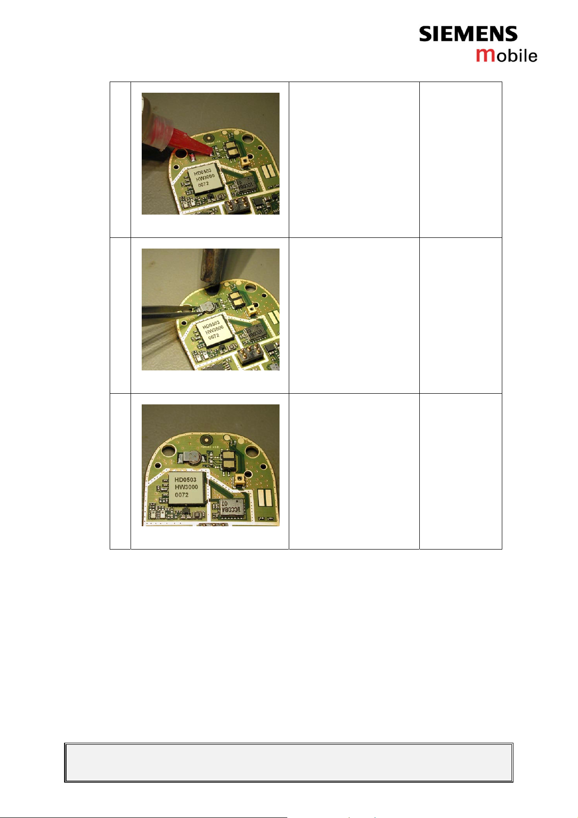
4
Figure 2-4
5
Add flux on the pads.
Re-solder the new
system connector by
using a hot air blower.
Check that the
connector is straight and
exactly in right place.
Figure 2-5
6
Figure 2-6
2.4.1.3 Repair by SW-Booting
Not possible!
New connector is in its
place.
2.4.1.4 Test
Charging problems can be discovered by measuring the voltage
between pins 1 (Power) and 2 (GND). Voltage should be between 5V
and 9,5V if system connector is working.
V1.1 Page 6 of 51 ICM CCQ GRM
Company Confidential
Level 2,5 C62 Copyright 2002 Siemens AG 10/2003
Page 7
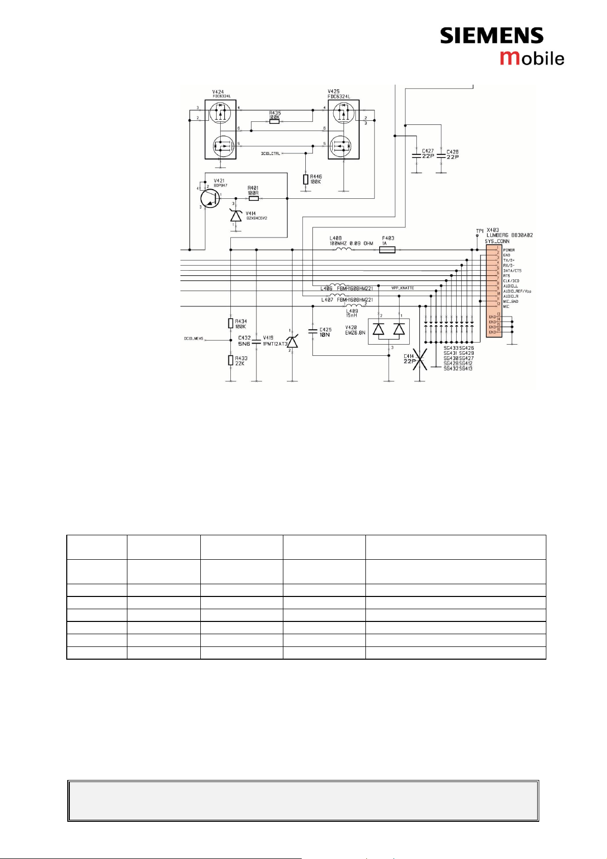
Circuit diagram of system connector
Test if accessories function well.
In order to detect an accessory when plugged into the system
connector, the following pins on the connector are used in the
detection scenario: POWER, TX/D+, RX/D-, DATA/CTS, CLK/DCD and
RTS. Table 1 shows the pins and their possible use in a detection
scenario.
Table 1: Accessory coding options
Pin No. Signal name Default level Default
1 POWER L(Z) Off Open or charge source (Set by
2 GND GND -
3 TX/D+ H(Z) Out High/Low (Set by Phone)
4 RX/D- L(Z) In Open, Tx or high (Set by accessory)
5 DATA/CTS H(Z) In Open, Tx or low (Set by accessory)
6 RTS H(Z) In Open, Tx or low (Set by accessory)
7 CLK/DCD H(Z) In Open, Tx or low (Set by accessory)
Possible coding options
direction
accessory)
The different coding options for the supported accessories can be seen
in Table 2.
V1.1 Page 7 of 51 ICM CCQ GRM
Company Confidential
Level 2,5 C62 Copyright 2002 Siemens AG 10/2003
Page 8
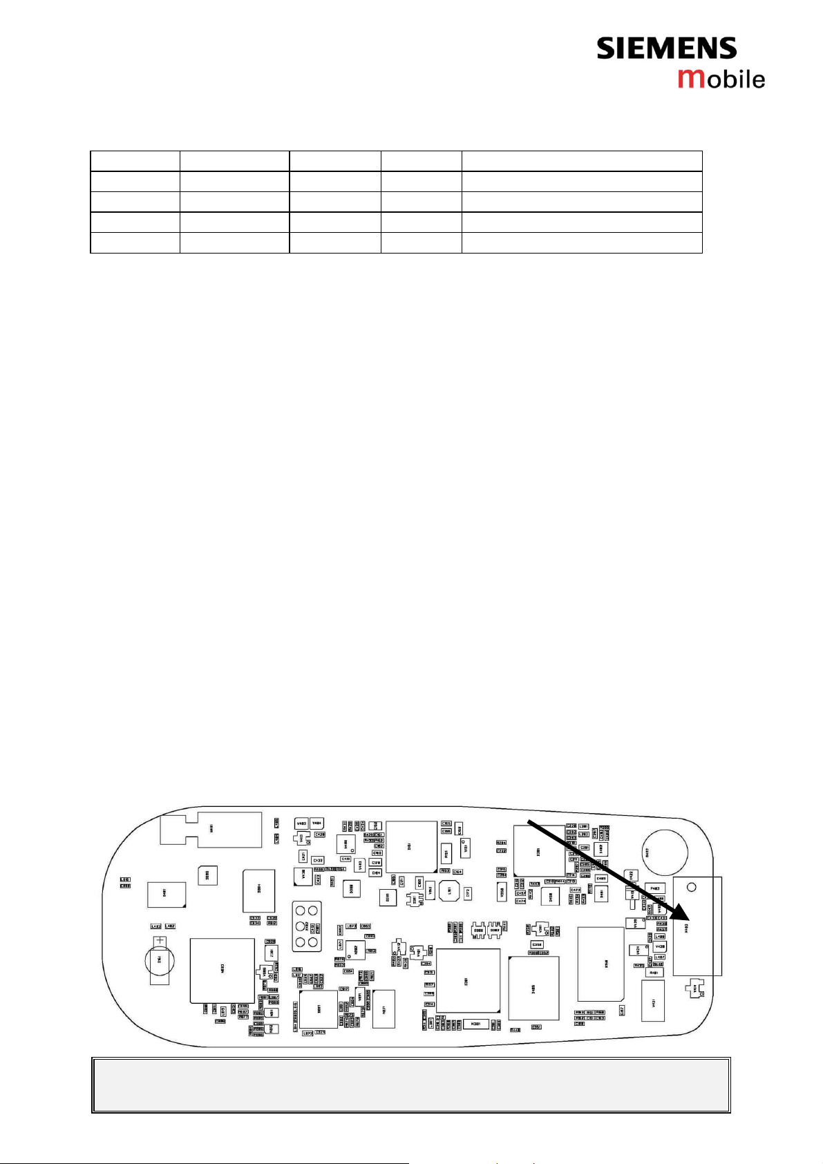
Table 2: Accessory coding table
RX/D- DATA/CTS CLK/DCD RTS Description
OPEN OPEN OPEN OPEN Default: No accessory connected
TX/D+ GND OPEN TX/D+ Headset
TX/D+ GND GND TX/D+ Headset with PTT pressed
HIGH OPEN GND OPEN Car Kit portable
2.4.2 List of needed material
2.4.2.1 Components
System connector female 12pin SMD
Part Number: L36197-F5121-F730
2.4.2.2 Jigs and Tools
Hot air blower
Tweezers
Inspection lamp
2.4.2.3 Special Tools
None
2.4.2.4 Working materials
Flux
Solder
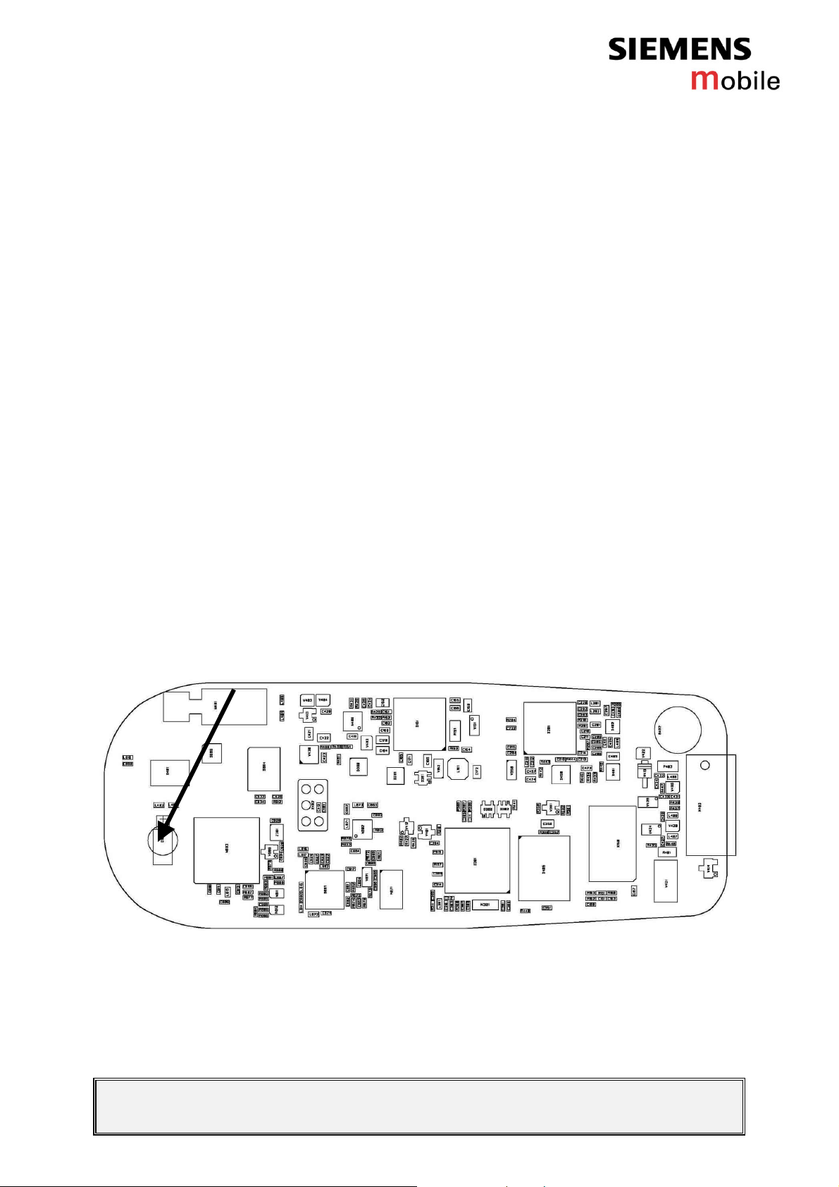
2.4.3 Drawings
Figure 1: C62 board, system connector side
V1.1 Page 8 of 51 ICM CCQ GRM
Company Confidential
Level 2,5 C62 Copyright 2002 Siemens AG 10/2003
Page 9
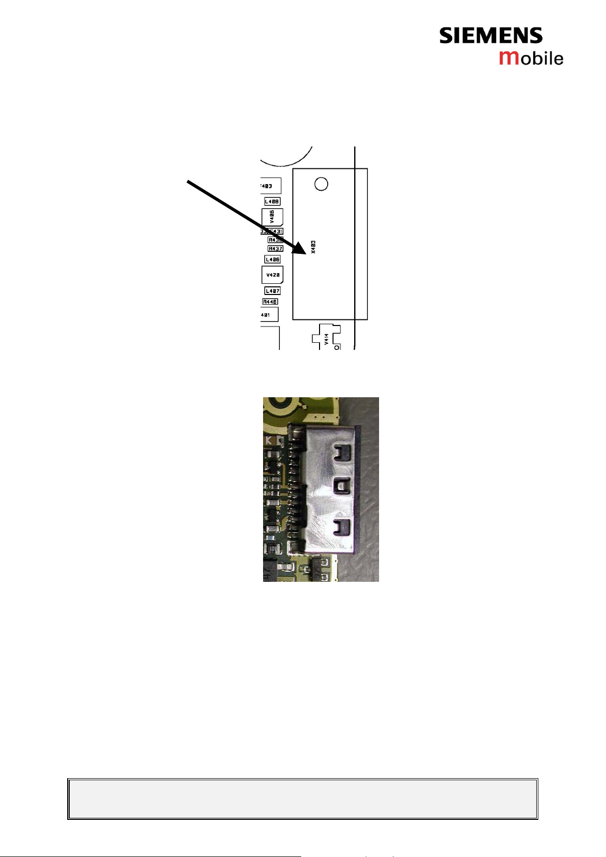
Figure 2: C62 system connector placement (top view)
Figure 3: C62 system connector
Table 3: Siemens C62 system connector pin description
V1.1 Page 9 of 51 ICM CCQ GRM
Company Confidential
Level 2,5 C62 Copyright 2002 Siemens AG 10/2003
Page 10
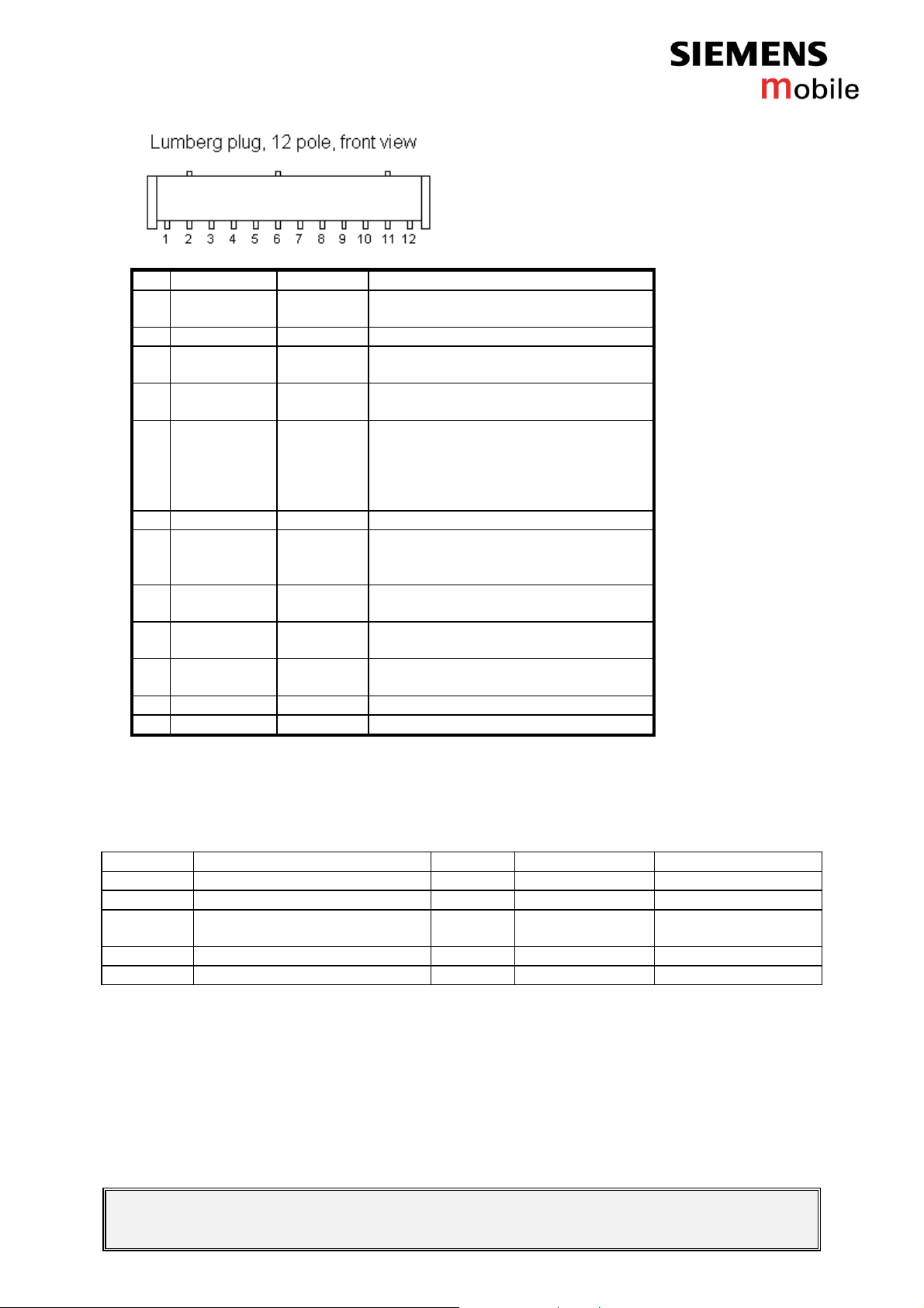
Pin Name IN/OUT Notes
1 POWER I Charging Current
2 GND Common GND
3 TX O Serial interface, used for Flash
programming and ITP commands
4 RX I Serial interface, used for Flash
programming and ITP commands
5 DATA/CTS I/O Serial interface, used for AT-
commands.
Data line for accessory bus.
Use as CTS in data operation.
Used for accessory detection
6 RTS I Used for accessory detection
7 CLK/DCD I/O Serial interface, used for AT-
commands.
Used for accessory detection
8 Audio L O Dual -ended (other end is Audio R)
output for external receiver (mono)
9 Audio_Ref/V
PP
I Used for 12V flash programming
voltage
10 Audio R O Dual -ended (other end is Audio L)
output for external receiver (mono)
11 Gnd_Micro GND external microphone
12 Micro I Input for external microphone
Table 4: Lumberg signal levels
Pin no. Signal name Level Min [V] Max [V]
3 TX/D+ VOH VOL 2.17 0 3.00 0.20
4 RX/D- VIH VIL 2.10 0 3.60 0.48
5 DATA/CTS VIH VIL
V
OH VOL
2.10 0 2.17 0 3.30 0.46 3.00 0.42
6 RTS VIH VIL 2.10 0 3.30 0.46
7 CLK/DCD VIH VIL 2.10 0 3.30 0.46
V1.1 Page 10 of 51 ICM CCQ GRM
Company Confidential
Level 2,5 C62 Copyright 2002 Siemens AG 10/2003
Page 11

3 RTC battery
3.1 Affected Units
3.1.1 Type: C62
3.1.2 Affected IMEIs / Date Codes: All / All
3.1.3 Affected SW-Versions: All
3.2 Fault Description
3.2.1 Fault Symptoms for customers:
The clock is reset when battery is switched off and on.
3.2.2 Fault Symptom on GSM-Tester:
This fault cannot be detected with a GSM-tester.
3.3 Priority:
........ Mandatory
⌧
........ Repair
........ Optional
........ Not Yet Defined
3.4 Repair Documentation
3.4.1 Description of procedure:
3.4.1.1 Diagnosis
Check the RTC battery visually. Watch for dry joints!
V1.1 Page 11 of 51 ICM CCQ GRM
Company Confidential
Level 2,5 C62 Copyright 2002 Siemens AG 10/2003
Page 12
3.4.1.2 Repair by component change
# Figure Instruction Note
1
Use a hot air blower to
remove the defective
RTC battery. Avoid
excessive heat!
Watch out for the
surrounding
components!
Figure 3-1
2
Figure 3-2
3
Figure 3-3
The defective RTC
battery is removed.
Add solder on the pads.
V1.1 Page 12 of 51 ICM CCQ GRM
Company Confidential
Level 2,5 C62 Copyright 2002 Siemens AG 10/2003
Page 13
4
Figure 3-4
5
Figure 3-5
Add flux on the pads.
Re-solder the new RTC
battery by using a hot air
blower and a soldering
iron if necessary. Check
that the RTC battery is
exactly in right place.
Watch surrounding
components!
6
Figure 3-6
3.4.1.3 Repair by SW-Booting
3.4.1.4 Test
Not possible!
Retest the handset after the repair.
If clock resets when battery is removed, RTC battery is faulty.
Measurement with voltage meter, the voltage should be 1.8V.
Note! If battery is empty, wait that it charges and voltage raises up to
1.8V.
New RTC battery is in its
place.
V1.1 Page 13 of 51 ICM CCQ GRM
Company Confidential
Level 2,5 C62 Copyright 2002 Siemens AG 10/2003
Page 14
3.4.2 List of needed material
3.4.2.1 Components
RTC-battery SMD VA6
Part Number: L36145-K1310-X293
3.4.2.2 Jigs and Tools
Hot air blower
Soldering iron
Tweezers
3.4.2.3 Special Tools
None
3.4.2.4 Working materials
Flux
Solder
3.4.3 Drawings
Figure 1: C62 board, RTC battery side
V1.1 Page 14 of 51 ICM CCQ GRM
Company Confidential
Level 2,5 C62 Copyright 2002 Siemens AG 10/2003
Page 15
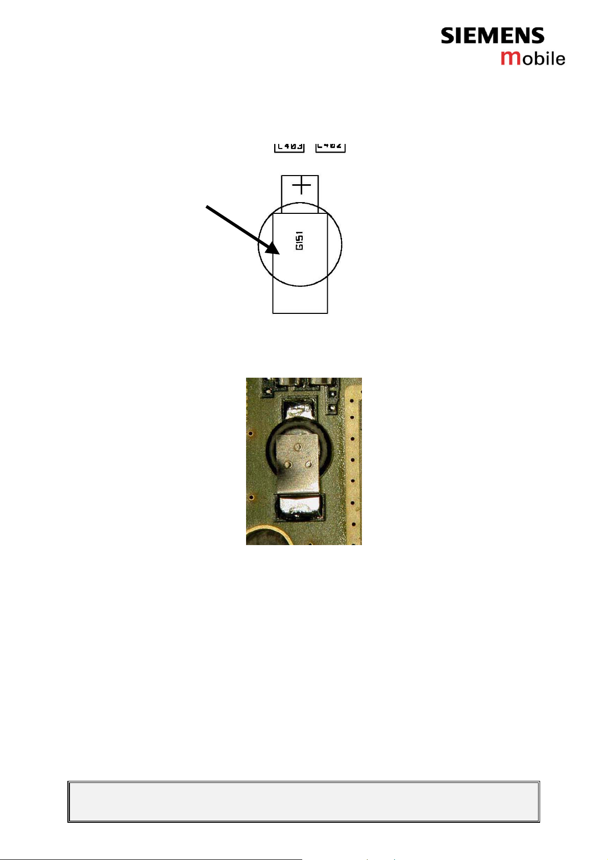
Figure 2: C62 RTC battery placement (top view)
Figure 3: C62 RTC battery
V1.1 Page 15 of 51 ICM CCQ GRM
Company Confidential
Level 2,5 C62 Copyright 2002 Siemens AG 10/2003
Page 16
4 Transistor SOT-323 (for LEDs)
4.1 Affected Units
4.1.1 Type: C62
4.1.2 Affected IMEIs / Date Codes: All / All
4.1.3 Affected SW-Versions: All
4.2 Fault Description
4.2.1 Fault Symptoms for customers:
4.2.2 Fault Symptom on GSM-Tester:
4.3 Priority:
........ Mandatory
⌧
........ Repair
........ Optional
........ Not Yet Defined
4.4 Repair Documentation
4.4.1 Description of procedure:
Display light does not work.
This fault cannot be detected with a GSM-tester.
4.4.1.1 Diagnosis
Check the transistor visually. Watch for dry joints!
V1.1 Page 16 of 51 ICM CCQ GRM
Company Confidential
Level 2,5 C62 Copyright 2002 Siemens AG 10/2003
Page 17

4.4.1.2 Repair by component change
# Figure Instruction Note
1
Use a hot air blower to
remove the defective
transistor. Avoid
excessive heat!
Watch out for the
surrounding
components!
Figure 4-1
2
Figure 4-2
3
Figure 4-3
Add solder on the pads.
Add flux on the pads.
V1.1 Page 17 of 51 ICM CCQ GRM
Company Confidential
Level 2,5 C62 Copyright 2002 Siemens AG 10/2003
Page 18

4
Figure 4-4
4.4.1.3 Repair by SW-Booting
4.4.1.4 Test
Re-solder the new
transistor by using a hot
air blower and a
soldering iron if
necessary. Watch
surrounding
components!
Not possible!
Retest the handset after the repair.
The circuit diagram of Transistor SOT-323 (for LEDs)
4.4.2 List of needed material
4.4.2.1 Components
TR NPN SOT323 SMD
Part number: L36197-F5122-F76
4.4.2.2 Jigs and Tools
Hot air blower
Soldering iron
Tweezers
V1.1 Page 18 of 51 ICM CCQ GRM
Company Confidential
Level 2,5 C62 Copyright 2002 Siemens AG 10/2003
Page 19

4.4.2.3 Special Tools
None
4.4.2.4 Working materials
Flux
Solder
4.4.3 Drawings
Figure 1: C62 board, transistor SOT323 (for LEDs) side
Figure 2: C62 transistor SOT323 (for LEDs) placement (top view)
V1.1 Page 19 of 51 ICM CCQ GRM
Company Confidential
Level 2,5 C62 Copyright 2002 Siemens AG 10/2003
Page 20

Figure 3: C62 transistor SOT323 (for LEDs)
V1.1 Page 20 of 51 ICM CCQ GRM
Company Confidential
Level 2,5 C62 Copyright 2002 Siemens AG 10/2003
Page 21

5 Transistor SOT-323 (for Vibra)
5.1 Affected Units
5.1.1 Type: C62
5.1.2 Affected IMEIs / Date Codes: All / All
5.1.3 Affected SW-Versions: All
5.2 Fault Description
5.2.1 Fault Symptoms for customers:
5.2.2 Fault Symptom on GSM-Tester:
5.3 Priority:
........ Mandatory
⌧
........ Repair
........ Optional
........ Not Yet Defined
5.4 Repair Documentation
5.4.1 Description of procedure:
Vibrator does not work.
This fault cannot be detected with a GSM-tester.
5.4.1.1 Diagnosis
Check the transistor visually. Watch for dry joints!
V1.1 Page 21 of 51 ICM CCQ GRM
Company Confidential
Level 2,5 C62 Copyright 2002 Siemens AG 10/2003
Page 22

5.4.1.2 Repair by component change
# Figure Instruction Note
1
Use a hot air blower to
remove the defective
transistor. Avoid
excessive heat!
Watch out for the
surrounding
components!
Figure 5-1
2
Figure 5-2
3
Figure 5-3
Add solder on the pads.
Add flux on the pads.
V1.1 Page 22 of 51 ICM CCQ GRM
Company Confidential
Level 2,5 C62 Copyright 2002 Siemens AG 10/2003
Page 23

4
Figure 5-4
5.4.1.3 Repair by SW-Booting
5.4.1.4 Test
Re-solder the new
transistor by using a hot
air blower and a
soldering iron if
necessary. Watch
surrounding
components!
Not possible!
Retest the handset after the repair.
- GROUND+LEFT VIBRA PAD should have VBATT (4.2V).
- COILS L404, L405 should have resistance of 1.0 Ohm.
Change V413 if vibrator does not work after replacement.
The circuit diagram of Transistor SOT-323 (for vibra)
5.4.2 List of needed material
5.4.2.1 Components
TR NPN SOT323 SMD
Part number: L36197-F5122-F76
5.4.2.2 Jigs and Tools
Hot air blower
Soldering iron
Tweezers
V1.1 Page 23 of 51 ICM CCQ GRM
Company Confidential
Level 2,5 C62 Copyright 2002 Siemens AG 10/2003
Page 24

5.4.2.3 Special Tools
None
5.4.2.4 Working materials
Flux
Solder
5.4.3 Drawings
Figure 1: C62 board, transistor SOT323 (for vibra) side
Figure 2: C62 transistor SOT323 (for vibra) placement (top
view)
V1.1 Page 24 of 51 ICM CCQ GRM
Company Confidential
Level 2,5 C62 Copyright 2002 Siemens AG 10/2003
Page 25

Figure 3: C62 transistor SOT323 (for Vibra)
V1.1 Page 25 of 51 ICM CCQ GRM
Company Confidential
Level 2,5 C62 Copyright 2002 Siemens AG 10/2003
Page 26

6 Fuse
6.1 Affected Units
6.1.1 Type: C62
6.1.2 Affected IMEIs / Date Codes: All / All
6.1.3 Affected SW-Versions: All
6.2 Fault Description
6.2.1 Fault Symptoms for customers:
6.2.2 Fault Symptom on GSM-Tester:
6.3 Priority:
........ Mandatory
⌧
........ Repair
........ Optional
........ Not Yet Defined
6.4 Repair Documentation
6.4.1 Description of procedure:
Charging does not work.
Accessories do not work.
This fault cannot be detected with a GSM-tester.
6.4.1.1 Diagnosis
Check the fuse visually. Watch for dry joints!
V1.1 Page 26 of 51 ICM CCQ GRM
Company Confidential
Level 2,5 C62 Copyright 2002 Siemens AG 10/2003
Page 27

6.4.1.2 Repair by component change
# Figure Instruction Note
1
Use a hot air blower to
remove the defective
fuse. Avoid excessive
heat!
Watch out for the
surrounding
components!
Figure 6-1
2
Figure 6-2
3
Figure 6-3
Add solder on the pads.
Add flux on the pads.
V1.1 Page 27 of 51 ICM CCQ GRM
Company Confidential
Level 2,5 C62 Copyright 2002 Siemens AG 10/2003
Page 28

4
Figure 6-4
6.4.1.3 Repair by SW-Booting
6.4.1.4 Test
Re-solder the new fuse
by using a hot air blower
and a soldering iron if
necessary. Watch
surrounding
components!
Not possible!
Retest the handset after the repair.
Measure resistance over fuse (F403), it should be 0 Ohm.
Measure transistor SOT-223 (V421) PIN1+GROUND, it should
be 6.2V (zener voltage), if it’s not, then the zener diode (V414)
is faulty.
Measure V421 PIN2+GROUND, it should be 8.3 V (charging
voltage, not charging mode), if it’s not, then the Voltage
suppressor (V419) is faulty.
Measure V421 PIN3+GROUND, it should be 5.7V (lowered
voltage), if it’s not, then the V421 is faulty.
The circuit diagram of Fuse
V1.1 Page 28 of 51 ICM CCQ GRM
Company Confidential
Level 2,5 C62 Copyright 2002 Siemens AG 10/2003
Page 29

6.4.2 List of needed material
6.4.2.1 Components
Fuse low profile 1A 1206 SMD
Part number: L36197-F5122-F79
6.4.2.2 Jigs and Tools
Hot air blower
Soldering iron
Tweezers
6.4.2.3 Special Tools
None
6.4.2.4 Working materials
Flux
Solder
6.4.3 Drawings
Figure 1: C62 board, fuse side
V1.1 Page 29 of 51 ICM CCQ GRM
Company Confidential
Level 2,5 C62 Copyright 2002 Siemens AG 10/2003
Page 30

Figure 2: C62 fuse placement (top view)
Figure 3: C62 fuse
V1.1 Page 30 of 51 ICM CCQ GRM
Company Confidential
Level 2,5 C62 Copyright 2002 Siemens AG 10/2003
Page 31

7 Voltage supressor
7.1 Affected Units
7.1.1 Type: C62
7.1.2 Affected IMEIs / Date Codes: All / All
7.1.3 Affected SW-Versions: All
7.2 Fault Description
7.2.1 Fault Symptoms for customers:
7.2.2 Fault Symptom on GSM-Tester:
7.3 Priority:
........ Mandatory
⌧
........ Repair
........ Optional
........ Not Yet Defined
7.4 Repair Documentation
7.4.1 Description of procedure:
Charging does not work.
Accessories do not work.
This fault cannot be detected with a GSM-tester.
7.4.1.1 Diagnosis
Check the voltage supressor visually. Watch for dry joints!
V1.1 Page 31 of 51 ICM CCQ GRM
Company Confidential
Level 2,5 C62 Copyright 2002 Siemens AG 10/2003
Page 32

7.4.1.2 Repair by component change
# Figure Instruction Note
1
Use a hot air blower to
remove the defective
voltage supressor. Avoid
excessive heat!
Watch out for the
surrounding
components!
Figure 7-1
2
Figure 7-2
3
Figure 7-3
Add solder on the pads.
Add flux on the pads.
V1.1 Page 32 of 51 ICM CCQ GRM
Company Confidential
Level 2,5 C62 Copyright 2002 Siemens AG 10/2003
Page 33

4
Figure 7-4
7.4.1.3 Repair by SW-Booting
7.4.1.4 Test
Re-solder the new
voltage supressor by
using a hot air blow and
a soldering iron if
necessary. Watch
surrounding
components!
Not possible!
Retest the handset after the repair.
Measure resistance over fuse (F403), it should be 0 Ohm.
Measure transistor SOT-223 (V421) PIN1+GROUND, it should
be 6.2V (zener voltage), if it’s not, then the zener diode (V414)
is faulty.
Measure V421 PIN2+GROUND, it should be 8.3 V (charging
voltage, not charging mode), if it’s not, then the Voltage
suppressor (V419) is faulty.
Measure V421 PIN3+GROUND, it should be 5.7V (lowered
voltage), if it’s not, then the V421 is faulty.
The circuit diagram of Voltage suppressor
V1.1 Page 33 of 51 ICM CCQ GRM
Company Confidential
Level 2,5 C62 Copyright 2002 Siemens AG 10/2003
Page 34

7.4.2 List of needed material
7.4.2.1 Components
Zener transient voltage supressor 12V max 1000W
Part number: L36197-F5122-F81
7.4.2.2 Jigs and Tools
Hot air blower
Soldering iron
Tweezers
7.4.2.3 Special Tools
None
7.4.2.4 Working materials
Flux
Solder
7.4.3 Drawings
Figure 1: C62 board, Voltage supressor side
V1.1 Page 34 of 51 ICM CCQ GRM
Company Confidential
Level 2,5 C62 Copyright 2002 Siemens AG 10/2003
Page 35

Figure 2: C62 Voltage supressor placement (top view)
Figure 3: C62 voltage supressor
V1.1 Page 35 of 51 ICM CCQ GRM
Company Confidential
Level 2,5 C62 Copyright 2002 Siemens AG 10/2003
Page 36

8 Transistor SOT-223
8.1 Affected Units
8.1.1 Type: C62
8.1.2 Affected IMEIs / Date Codes: All / All
8.1.3 Affected SW-Versions: All
8.2 Fault Description
8.2.1 Fault Symptoms for customers:
8.2.2 Fault Symptom on GSM-Tester:
8.3 Priority:
........ Mandatory
⌧
........ Repair
........ Optional
........ Not Yet Defined
8.4 Repair Documentation
8.4.1 Description of procedure:
Charging does not work.
This fault cannot be detected with a GSM-tester.
8.4.1.1 Diagnosis
Check the transistor visually. Watch for dry joints!
V1.1 Page 36 of 51 ICM CCQ GRM
Company Confidential
Level 2,5 C62 Copyright 2002 Siemens AG 10/2003
Page 37

8.4.1.2 Repair by component change
# Figure Instruction Note
1
Use a hot air blower to
remove the defective
transistor. Avoid
excessive heat!
Watch out for the
surrounding
components!
Figure 8-1
2
Figure 8-2
3
Figure 8-3
Add solder on the pads.
Add flux on the pads.
V1.1 Page 37 of 51 ICM CCQ GRM
Company Confidential
Level 2,5 C62 Copyright 2002 Siemens AG 10/2003
Page 38

4
Re-solder the new
transistor by using a hot
air blower and a
soldering iron if
necessary. Watch
surrounding
components!
Figure 8-4
8.4.1.3 Repair by SW-Booting
Not possible!
8.4.1.4 Test
Retest the handset after the repair.
Measure resistance over fuse (F403), it should be 0 Ohm.
Measure
transistor SOT-223 (V421) PIN1+GROUND, it should be
6.2V (zener voltage), if it’s not, then the zener diode (V414) is
faulty.
Measure V421
PIN2+GROUND, it should be 8.3 V (charging
voltage, not charging mode), if it’s not, then the Voltage
suppressor (V419) is faulty.
Measure V421 PIN3+GROUND, it should be 5.7V (lowered
voltage), if it’s not, then the V421 is faulty.
The circuit diagram of Transistor SOT-223
V1.1 Page 38 of 51 ICM CCQ GRM
Company Confidential
Level 2,5 C62 Copyright 2002 Siemens AG 10/2003
Page 39

8.4.2 List of needed material
8.4.2.1 Components
Transistor NPN SOT-223
Part number: L36197-F5122-F77
8.4.2.2 Jigs and Tools
Hot air blower
Soldering iron
Tweezers
8.4.2.3 Special Tools
None
8.4.2.4 Working materials
Flux
Solder
8.4.3 Drawings
Figure 1: C62 board, transistor SOT-223 side
V1.1 Page 39 of 51 ICM CCQ GRM
Company Confidential
Level 2,5 C62 Copyright 2002 Siemens AG 10/2003
Page 40

Figure 2: C62 transistor SOT-223 placement (top view)
Figure 3: C62 transistor SOT-223
V1.1 Page 40 of 51 ICM CCQ GRM
Company Confidential
Level 2,5 C62 Copyright 2002 Siemens AG 10/2003
Page 41

9 Zener diode
9.1 Affected Units
9.1.1 Type: C62
9.1.2 Affected IMEIs / Date Codes: All / All
9.1.3 Affected SW-Versions: All
9.2 Fault Description
9.2.1 Fault Symptoms for customers:
9.2.2 Fault Symptom on GSM-Tester:
9.3 Priority:
........ Mandatory
⌧
........ Repair
........ Optional
........ Not Yet Defined
9.4 Repair Documentation
9.4.1 Description of procedure:
Charging does not work.
This fault cannot be detected with a GSM-tester.
9.4.1.1 Diagnosis
Check the zener diode visually. Watch for dry joints!
V1.1 Page 41 of 51 ICM CCQ GRM
Company Confidential
Level 2,5 C62 Copyright 2002 Siemens AG 10/2003
Page 42

9.4.1.2 Repair by component change
# Figure Instruction Note
1
Use a hot air blower to
remove the defective
zener diode. Avoid
excessive heat!
Watch out for the
surrounding
components!
Figure 9-1
2
Figure 9-2
3
Figure 9-3
Add solder on the pads.
Add flux on the pads.
V1.1 Page 42 of 51 ICM CCQ GRM
Company Confidential
Level 2,5 C62 Copyright 2002 Siemens AG 10/2003
Page 43

4
Re-solder the new zener
diode by using a hot air
blower and a soldering
iron if necessary. Watch
surrounding
components!
Figure 9-4
9.4.1.3 Repair by SW-Booting
Not possible!
9.4.1.4 Test
Retest the handset after the repair.
Measure resistance over fuse (F403), it should be 0 Ohm.
Measure transistor SOT-223 (V421) PIN1+GROUND, it should
be 6.2V (zener voltage), if it’s not, then the zener diode (V414)
is faulty.
Measure V421 PIN2+GROUND, it should be 8.3 V (charging
voltage, not charging mode), if it’s not, then the Voltage
suppressor (V419) is faulty.
Measure V421 PIN3+GROUND, it should be 5.7V (lowered
voltage), if it’s not, then the V421 is faulty.
The circuit diagram of Zener diode
V1.1 Page 43 of 51 ICM CCQ GRM
Company Confidential
Level 2,5 C62 Copyright 2002 Siemens AG 10/2003
Page 44

9.4.2 List of needed material
9.4.2.1 Components
Zener diode 6.2V max 350mW SOT23 SMD
Part number: L36197-F5122-F78
9.4.2.2 Jigs and Tools
Hot air blower
Soldering iron
Tweezers
9.4.2.3 Special Tools
None
9.4.2.4 Working materials
Flux
Solder
9.4.3 Drawings
Figure 1: C62 board, zener diode side
V1.1 Page 44 of 51 ICM CCQ GRM
Company Confidential
Level 2,5 C62 Copyright 2002 Siemens AG 10/2003
Page 45

Figure 2: C62 zener diode placement (top view)
Figure 3: C62 zener diode
V1.1 Page 45 of 51 ICM CCQ GRM
Company Confidential
Level 2,5 C62 Copyright 2002 Siemens AG 10/2003
Page 46

10 LED color yellow
10.1 Affected Units
10.1.1 Type: C62
10.1.2 Affected IMEIs / Date Codes: All / All
10.1.3 Affected SW-Versions: All
10.2 Fault Description
10.2.1 Fault Symptoms for customers:
10.2.2 Fault Symptom on GSM-Tester:
10.3 Priority:
........ Mandatory
⌧
........ Repair
........ Optional
........ Not Yet Defined
10.4 Repair Documentation
No even light in the keymat or dark area in the
keymat.
LEDs are not lit.
This fault cannot be detected with a GSM-tester.
10.4.1 Description of procedure:
10.4.1.1 Diagnosis
Check the yellow LED visually.
Use the diode test function of a multimeter to check the status of the
diode.
V1.1 Page 46 of 51 ICM CCQ GRM
Company Confidential
Level 2,5 C62 Copyright 2002 Siemens AG 10/2003
Page 47

The typical voltage drop on the diode is 1.7V when testing the diode
function with the multimeter.
10.4.1.2 Repair by component change
# Figure Instruction Note
1
Remove the domesheet
from the PWB.
Figure 10-1
2
Figure 10-2
3
Figure 10-3
Use a hot air blower to
remove the defective
yellow LED. Avoid
excessive heat!
Watch out for the
surrounding
components!
Add solder on the pads.
V1.1 Page 47 of 51 ICM CCQ GRM
Company Confidential
Level 2,5 C62 Copyright 2002 Siemens AG 10/2003
Page 48

4
Figure 10-4
5
Figure 10-5
Add flux on the pads.
Place the LED according
to Fig.13-5, anode on
the right, cathode on the
left.
Direction of
the board in
the picture:
system
connector is at
the bottom
(See Fig.13-6)
6
Figure 10-6
7
Figure 10-7
Re-solder the new
yellow LED by using a
hot air blower and a
soldering iron if
necessary. Watch
surrounding
components!
V1.1 Page 48 of 51 ICM CCQ GRM
Company Confidential
Level 2,5 C62 Copyright 2002 Siemens AG 10/2003
Page 49

8
Figure 10-8
10.4.1.3 Repair by SW-Booting
10.4.1.4 Test
Not possible!
Retest the handset after the repair.
Adding voltage (1.8V) on one of the LED, If LEDs work well, the
light is lid.
- If single LED is empty, one can be changed (LEDs are in
parallel connection).
- If all LEDs are empty, check TR SOT-323 (V412) with
voltage meter.
- Voltage over V412 should be over 0.5V.
Mount the domesheet in
its place. Use a new
domesheet if the old one
was damaged during
removal.
Use the the
dome sheet
Jig.
F30032-P333A1
- PIN1+GROUND (when light is on) voltage should be
1.6V.
- PIN3+GROUND (when light is on) voltage should be
VBATT-1.8V (2.8V).
The circuit diagram of the LED color yellow
V1.1 Page 49 of 51 ICM CCQ GRM
Company Confidential
Level 2,5 C62 Copyright 2002 Siemens AG 10/2003
Page 50

10.4.2 List of needed material
10.4.2.1 Components
LED yellow 1.60x0.8x0.6mm SMD
Part number: L36197-F5122-F72
10.4.2.2 Jigs and Tools
Hot air blower
Soldering iron
Tweezers
10.4.2.3 Special Tools
None
10.4.2.4 Working materials
Flux
Solder
10.4.3 Drawings
Figure 1: C62 board, LED colour yellow side
V1.1 Page 50 of 51 ICM CCQ GRM
Company Confidential
Level 2,5 C62 Copyright 2002 Siemens AG 10/2003
Page 51

Figure 2: C62 LED colour yellow placement (top view)
Figure 3: C62 LED colour yellow
V1.1 Page 51 of 51 ICM CCQ GRM
Company Confidential
Level 2,5 C62 Copyright 2002 Siemens AG 10/2003
 Loading...