

Page 1

Siemens BT300 HVAC Drive
Operator's Manual
DPD01809
Building Technologies
2016-06-07
Page 2

Copyright Notice
2 | 180
Siemens Industry, Inc.
Siemens BT300 HVAC Drive
DPD01809
Building Technologies
2016-06-07
Copyright Notice
Notice
Document information is subject to change without notice by Siemens Industry, Inc.
Companies, names, and various data used in examples are fictitious unless otherwise
noted. No part of this document may be reproduced or transmitted in any form or by
any means, electronic or mechanical, for any purpose, without the express written
permission of Siemens Industry, Inc.
Warning
This equipment generates, uses, and can radiate radio frequency energy. If equipment
is not installed and used in accordance with the instructions manual, it may cause
interference to radio communications. Equipment has been tested and found to comply
within the limits for a Class B digital device pursuant to Part 15 of the FCC rules. These
limits are designed to provide reasonable protection against such interference when
operated in a commercial environment. Operation of this equipment in a residential
area is likely to cause interference. Residential area equipment users are required to
take whatever measures necessary to correct the interference at their own expense.
Service Statement
Control devices are combined to make a system. Each control device is mechanical in
nature and all mechanical components must be regularly serviced to optimize their
operation. Siemens Industry, Inc. branch offices and authorized distributors offer
Technical Support Programs that will ensure continuous, trouble-free system
performance.
For further information, contact your nearest Siemens Industry representative.
Copyright Siemens Industry, Inc.
FCC Regulations
The manual for an intentional or unintentional radiator shall caution the user that
changes or modifications not expressly approved by the party responsible could void
the user’s authority to operate the equipment.
For a Class B digital device or peripheral, the instructions furnished the user shall
include the following or similar statement, placed in a prominent location in the text of
the manual:
NOTE: This equipment has been tested and found to comply with the limits for a Class
B digital device, pursuant to part 15 of the FCC Rules. These limits are designed to
provide reasonable protection against harmful interference in a residential installation.
This equipment generates, uses and can radiate radio frequency energy and, if not installed and used in accordance with the instructions, may cause harmful interference to
radio communications. However, there is no guarantee that interference will not occur
in a particular installation. If this equipment does cause harmful interference to radio or
television reception, which can be determined by turning the equipment off and on, the
user is encouraged to try to correct the interference by one or more of the following
measures:
●
●
●
●
Reorient or relocate the receiving antenna.
Increase the separation between the equipment and receiver.
Connect the equipment into an outlet on a circuit different from that to which the
receiver is connected.
Consult the dealer or an experienced radio/TV technician for help.
Page 3

Copyright Notice
3 | 180
Siemens Industry, Inc.
Siemens BT300 HVAC Drive
DPD01809
Building Technologies
2016-06-07
To the Reader
Your feedback is important to us. If you have comments about this manual, please
submit them to: SBT_technical.editor.us.sbt@siemens.com
Credits
APOGEE is a registered trademark of Siemens Industry, Inc. Other product or
company names mentioned herein may be the trademarks of their respective owners.
Printed in the USA.
Page 4

Copyright Notice
4 | 180
Siemens Industry, Inc.
Siemens BT300 HVAC Drive
DPD01809
Building Technologies
2016-06-07
Page 5

5 | 180
Siemens Industry, Inc.
Siemens BT300 HVAC Drive
DPD01809
Building Technologies
2016-06-07
Table of contents
How to Use this Manual .............................................................................................. 9
Chapter 1 - User Interfaces on Siemens BT300 ........................................................ 11
Drive keypad .................................................................................................................. 11
Keypad buttons ................................................................................................... 11
Keypad display..................................................................................... 12
Using the keypad ................................................................................. 13
NET (Software Tool) ...................................................................................................... 15
Fieldbus ......................................................................................................................... 16
Chapter 2 - Control Board Terminal Connections ...................................................... 17
Analog Input Terminal Connections .............................................................................. 18
Analog Input 1 ..................................................................................................... 18
Analog Input 2 ..................................................................................................... 18
Digital Input Terminal Connections ............................................................................... 19
Digital Inputs 1 through 6 .................................................................................... 19
Analog Output Terminal Connections ........................................................................... 19
Analog Output 1 .................................................................................................. 19
Digital Output Terminal Connections ............................................................................. 20
Chapter 3 - Start-up Information ............................................................................... 21
Procedure and Checklist ............................................................................................... 21
Commissioning Flowchart ............................................................................................. 21
Wizards .......................................................................................................................... 22
Startup Wizard (P1.19) ........................................................................................ 22
PID Mini-Wizard (P1.17) ..................................................................................... 24
Multi-Pump Wizard (P1.18) ................................................................................. 25
Fire Mode Wizard (P1.20) ................................................................................... 25
Bypass Wizard (P1.21) ....................................................................................... 26
Chapter 4 - Parameters and Menu Structure ............................................................. 28
Quick Setup (M1) ........................................................................................................... 29
Monitor Menu (M2) ........................................................................................................ 30
Multimonitor (M2.1) ............................................................................................. 30
Basic (M2.2) ........................................................................................................ 31
Timer functions monitoring (M2.3) ...................................................................... 32
PID Controller 1 Monitoring (M2.4) ..................................................................... 33
PID Controller 2 Monitoring (M2.5) ..................................................................... 33
Multi-pump monitoring (M2.6) ............................................................................. 33
Fieldbus data monitoring (M2.8) ......................................................................... 34
Temperature inputs monitoring (M2.9) ................................................................ 35
Parameters (M3) ............................................................................................................ 35
Motor Settings (M3.1) .......................................................................................... 35
Page 6

Siemens Industry, Inc.
Siemens BT300 HVAC Drive
DPD01809
Building Technologies
2016-06-07
6 | 180
Basic Settings (M3.1.1) ........................................................................ 36
Motor Control Settings (M3.1.2) ........................................................... 36
Start/Stop setup (M3.2) ....................................................................................... 38
Start Function (P3.2.4) ......................................................................... 40
Stop Function (P3.2.5) ......................................................................... 41
I/O start/stop logic (P3.2.6) .................................................................. 41
Control reference settings (M3.3) ........................................................................ 47
Understanding Preset Frequencies ..................................................... 50
Ramp and Brakes Setup (M3.4) .......................................................................... 51
I/O Configuration (M3.5) ...................................................................................... 53
Digital Inputs (M3.5.1) .......................................................................... 53
Analog Inputs (M3.5.2)......................................................................... 57
Digital Outputs (M3.5.3) ....................................................................... 60
Analog Outputs (M3.5.4) ...................................................................... 63
Fieldbus Data Mapping (M3.6) ............................................................................ 66
Prohibited Frequencies (M3.7) ............................................................................ 69
Limit supervisions (M3.8) .................................................................................... 70
Protections (M3.9) ............................................................................................... 72
Automatic Reset (M3.10)..................................................................................... 79
Timer Functions (M3.11) ..................................................................................... 81
Time Channels ..................................................................................... 81
Intervals ............................................................................................... 81
Timers .................................................................................................. 84
Example ............................................................................................... 84
PID Controller 1 (M3.12) ..................................................................................... 85
Basic Settings (M3.12.1) ...................................................................... 85
Setpoints (M3.12.2) .............................................................................. 86
Feedbacks (M3.12.3) ........................................................................... 88
Feedforward (M3.12.4) ........................................................................ 90
Process Supervision (M3.12.5) ............................................................ 91
Pressure Loss Compensation (M3.12.6) ............................................. 92
PID Control Sequence Details ............................................................. 92
PID Controller 2 (M3.13) ..................................................................................... 97
Basic Settings (M3.13.1) ...................................................................... 98
Setpoints (M3.13.2) .............................................................................. 98
Feedback (M3.13.3) ............................................................................. 99
Process Supervision (M3.13.4) .......................................................... 100
Multi-pump (M3.14) ........................................................................................... 100
Multi-Pump ......................................................................................... 101
Fire mode (M3.16) ............................................................................................. 105
Application settings (M3.17) .............................................................................. 108
Bypass (M3.18) ................................................................................................. 108
Diagnostics (M4) .......................................................................................................... 110
Page 7

7 | 180
Siemens Industry, Inc.
Siemens BT300 HVAC Drive
DPD01809
Building Technologies
2016-06-07
Active faults (M4.1)............................................................................................ 110
Reset faults (P4.2)............................................................................................. 110
Fault History (M4.4) ........................................................................................... 110
Total Counters (M4.6) ....................................................................................... 111
Trip Counters (M4.7) ......................................................................................... 111
Software Info (M4.8) .......................................................................................... 112
I/O and Hardware (M5) ................................................................................................ 112
Basic I/O (M5.1) ................................................................................................ 112
Slot C (M5.2) ..................................................................................................... 113
Slot D (M5.3) ..................................................................................................... 113
Slot E (M5.4) ..................................................................................................... 114
Real time clock (M5.5) ...................................................................................... 114
Power unit settings (M5.6) ................................................................................ 114
Fan (M5.6.1) ...................................................................................... 114
Sine Filter (M5.6.4) ............................................................................ 115
Keypad (M5.7) ................................................................................................... 115
RS-485 (M5.8) ................................................................................................... 116
Common Settings (M5.8.1) ................................................................ 117
N2 (M5.8.3) ........................................................................................ 118
BACnet MS/TP (M5.8.3) .................................................................... 123
P1 FLN (M5.8.3) ................................................................................ 131
Modbus RTU (M5.8.3) ....................................................................... 136
Ethernet (M.5.9) ................................................................................................ 152
Common Settings (M5.9.1) ................................................................ 152
Modbus TCP (M5.9.2) ....................................................................... 153
BACnet IP (M5.9.3) ............................................................................ 158
User Settings (M6) ....................................................................................................... 162
Parameter Backup (M6.5) ................................................................................. 162
Parameter Compare (M6.6) .............................................................................. 163
Favorites (M7) ............................................................................................................. 163
User Levels (M8) ......................................................................................................... 163
Chapter 5 - Fault tracing ......................................................................................... 165
Fault Displays .............................................................................................................. 165
Fault history ................................................................................................................. 165
Fault codes .................................................................................................................. 166
Chapter 6 - Technical Information ........................................................................... 171
Product Numbers ......................................................................................................... 171
Power Ratings ............................................................................................................. 172
Interpreting Serial Numbers and Date Codes ............................................................. 172
Technical Data ............................................................................................................. 173
Control Board Technical Specifications ....................................................................... 175
Fieldbus Technical Data .............................................................................................. 176
Accessories and Replacement Parts .......................................................................... 177
Page 8

Page 9

How to Use this Manual
9 | 180
Siemens Industry, Inc.
Siemens BT300 HVAC Drive
DPD01809
Building Technologies
2016-06-07
Convention
Examples
Numbered Lists (1, 2, 3…) indicate a
procedure with sequential steps.
1. Turn OFF power to the field panel.
2. Turn ON power to the field panel.
3. Contact the local Siemens Industry representative.
Conditions that must be completed or met
before beginning a task are designated with a
⊳.
Intermediate results (what will happen
following the execution of a step), are
designated with a ⇨.
Results, which inform the user that a task was
completed successfully, are designated with a
⇨.
⊳Composer software is properly installed.
⊳A Valid license is available.
1. Select Start > Programs > Siemens > GMS >
Composer.
⇨The Project Management window displays.
2. Open an existing project or create a new one.
⇨The project window displays.
Actions that should be performed are specified
in boldface font.
Type F for Field panels.
Click OK to save changes and close the dialog box.
Error and system messages are displayed in
Courier New font.
The message Report Definition successfully
renamed displays in the status bar.
New terms appearing for the first time are
italicized.
The field panel continuously executes a user-defined set
of instructions called the
control program
.
This symbol signifies Notes. Notes provide additional
information or helpful hints.
Cross references to other information are
indicated with an arrow and the page number,
enclosed in brackets: [→92]
For more information on creating flowcharts, see
Flowcharts [→92].
Placeholders indicate text that can vary based
on your selection. Placeholders are specified
by italicized letters, and enclosed with brackets
[ ].
Type A C D H [
username
] [
field panel #]
.
How to Use this Manual
About This Manual
This manual is written for the owner and user of the BT300 HVAC Variable Speed Drive. It is designed to help you
become familiar with the BT300 HVAC Variable Speed Drive and its applications.
This section covers manual organization, document conventions and symbols used in the manual, how to access
help, related publications, and any other information that will help you use this manual.
Document Conventions
The following table lists conventions to help you use this manual in a quick and efficient manner.
Page 10
How to Use this Manual
10 | 180
Siemens Industry, Inc.
Siemens BT300 HVAC Drive
DPD01809
Building Technologies
2016-06-07
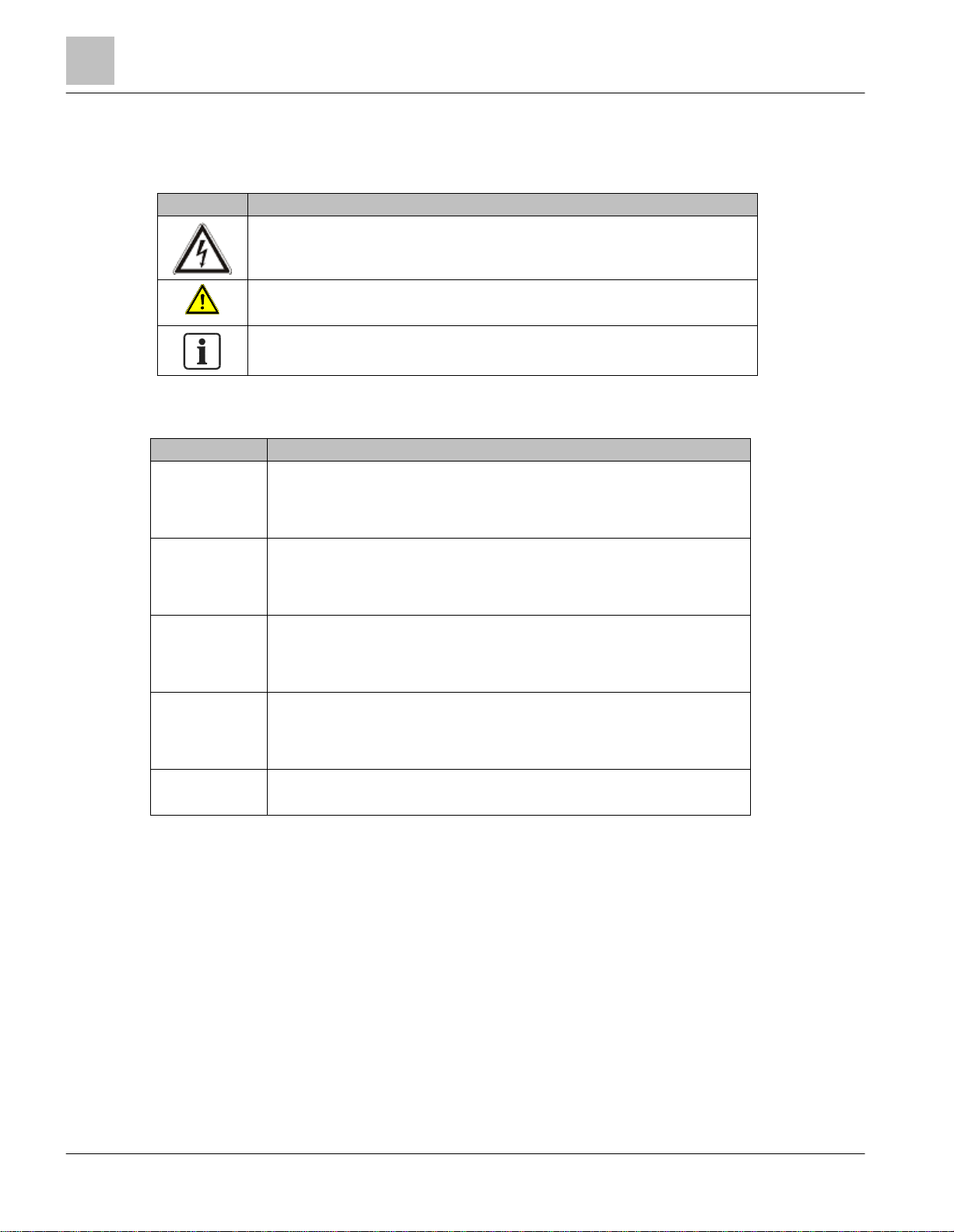
Symbol
Description
DANGER or WARNING: Dangerous voltage is present.
DANGER ou AVERTISSEMENT: Présence de tension dangereuse.
WARNING or CAUTION
AVERTISSEMENT ou ATTENTION
NOTE
REMARQUE
Warning Type
Description
DANGER
Serious injury, death, or severe equipment damage is imminent if a procedure or
instruction is not followed as specified.
Le non respect d'une procédure ou instruction peut provoquer instantanément des
blessures graves, voir mortelles, ou endommager l'équipement
WARNING
Serious injury, death, or severe equipment damage could occur if a procedure or
instruction is not followed as specified.
Le non respect d'une procédure ou instruction peut provoquer des blessures graves
voir mortelles ou endommager l'équipement.
CAUTION
Minor or moderate injury may occur if a procedure or instruction is not followed as
specified.
Le non respect d'une procédure ou instruction peut provoquer des blessures
mineures ou modérés.
NOTICE
Equipment damage or unwanted operation may occur if a procedure or instruction is
not followed as specified.
Le non respect d'une procédure ou instruction peut endommager l'équipement ou
entraîner un fonctionnement intempestif.
NOTE
Notes provide additional information or helpful hints.
Les remarques fournissent des informations supplémentaires ou des conseils utiles.
Safety Symbols
The following table lists the safety symbols used in this manual to draw attention to important information.
The following table describes the safety notices used in this manual to draw attention to important information.
Table 1: Warning Symbols.
Table 2: Warning Descriptions.
Getting Help
For more information about BT300 products, contact your local Siemens Industry representative.
Page 11
Chapter 1 - User Interfaces on Siemens BT300
Drive Keypad
11 | 180
Siemens Industry, Inc.
Siemens BT300 HVAC Drive
DPD01809
Building Technologies
2016-06-07
Chapter 1 - User Interfaces on Siemens BT300
This chapter presents the different user interfaces on Siemens BT300:
● Keypad
● Siemens NET
● Fieldbus
Drive Keypad
The control keypad with graphical interface is the interface between the Siemens BT300 HVAC Drive and the user.
With the control keypad it is possible to control the speed of a motor, to supervise the state of the equipment and
to set the variable frequency driver's parameters.
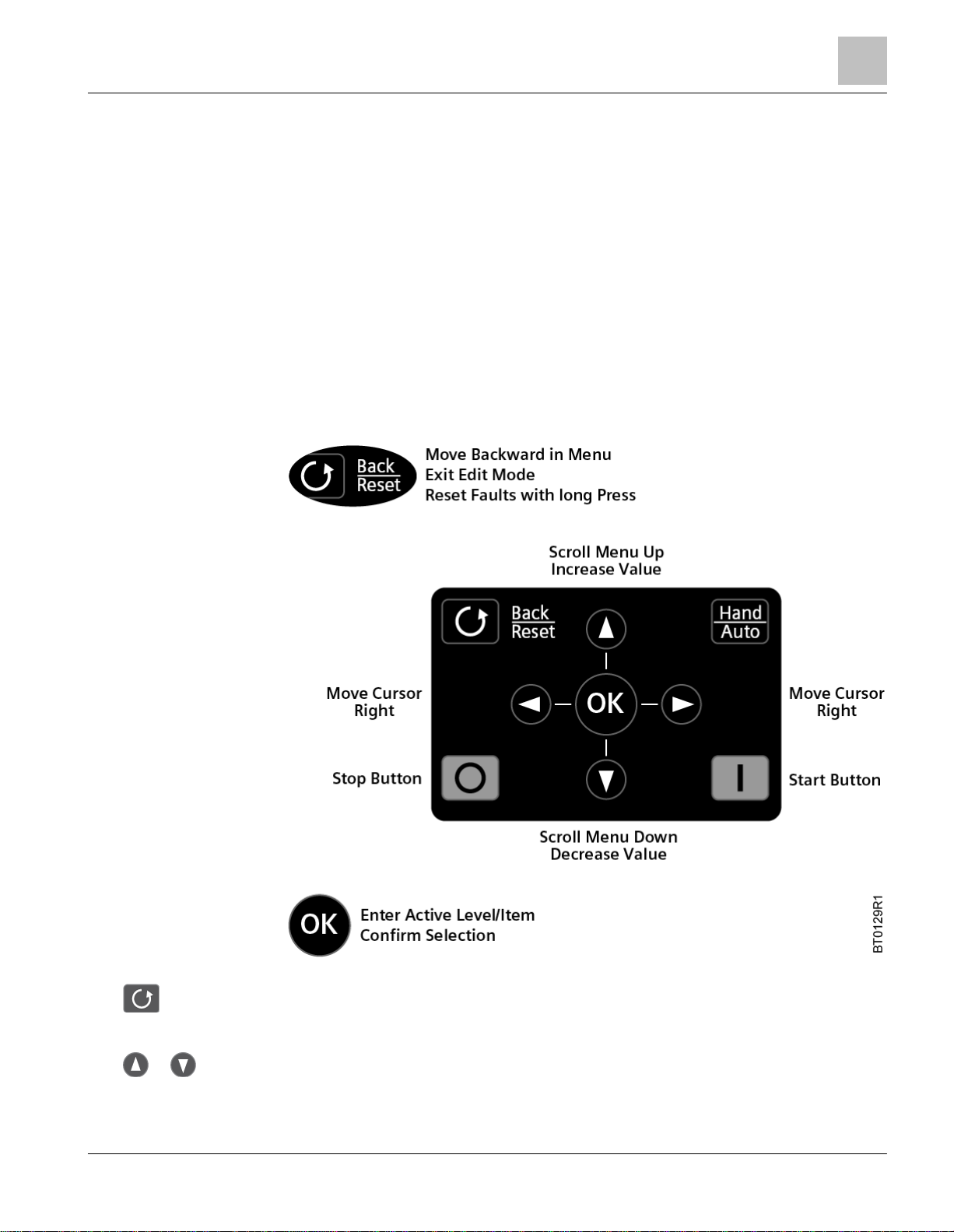
Keypad Buttons
The keypad features nine buttons used to configure and control the drive.
● This button (back/reset) allows you to move backwards in the menu, backup a step when using a wizard,
● or These buttons allow you to scroll up (or down) in the menu or increase (or decrease) a parameter
Figure 1: Keypad Buttons.
exit the edit mode, or reset a fault (when held for approximately one second).
value when editing.
Page 12
Chapter 1 - User Interfaces on Siemens BT300
Drive Keypad
12 | 180
Siemens Industry, Inc.
Siemens BT300 HVAC Drive
DPD01809
Building Technologies
2016-06-07
● or These buttons allow you to move the cursor left (or right) when editing a parameter value.
● This button allows you to move to the next step when using a wizard, select an item in the menu, or
select a setting for a parameter when editing.
● This button allows you to quickly access the Control Page and to easily change between the Hand
(Keypad) or Auto mode of operation. If an Electronic Bypass is present, this button provides access to the
drive-off bypass functions.
● This button allows you to start the drive in Keypad (Hand) mode of operation.
● This button allows you to stop the drive in Keypad (Hand) mode of operation. This button can also be
used as an emergency stop (unless limited by the Keypad Stop Button [P3.2.3]).
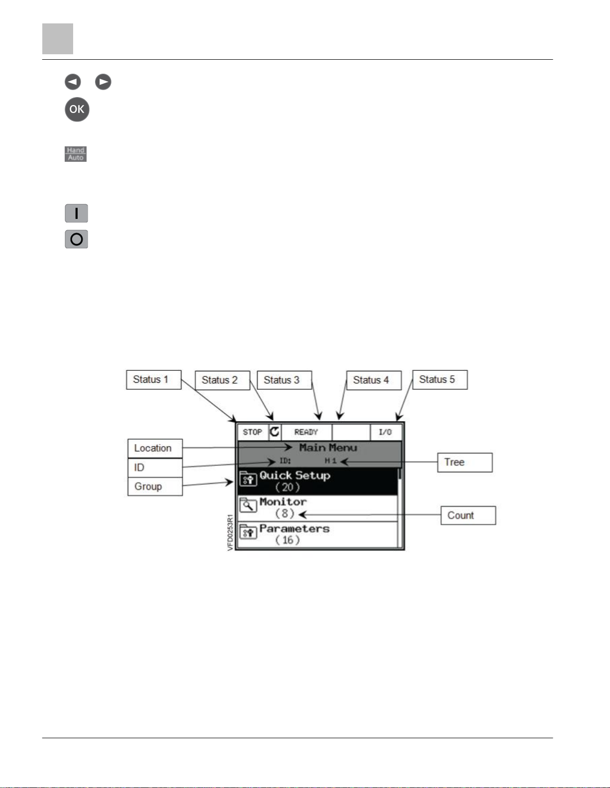
Keypad Display
The keypad display indicates the status of the motor and the drive and any irregularities in motor or drive functions.
On the display, you can view information about the present location in the menu structure and the item displayed.
See
Chapter 4
Several pieces of information are available on the display at any given moment. Five status fields are provided
across the top of the display, as well as the location/parameter selected. Group information is also available.
These fields are:
● Status 1: Indicates the drive’s run status.
● Status 2: Indicates the drive’s run direction.
● Status 3: Indicates if the drive is READY to run, NOT READY to run, in FAULT, or in BYPASS (if Electronic
Bypass is enabled).
● Status 4: Indicates if the drive is in ALARM.
● Status 5: Indicates the current control place, such as I/O, FB, KEYPAD, PC, or OFF (if Electronic Bypass is
enabled).
● Location: Indicates the Menu name, Sub-menu name, or parameter name that is currently selected.
for a comprehensive view of the menu structure.
Figure 2: Keypad Display.
Page 13

Chapter 1 - User Interfaces on Siemens BT300
Drive Keypad
13 | 180
Siemens Industry, Inc.
Siemens BT300 HVAC Drive
DPD01809
Building Technologies
2016-06-07
NOTE:
This field always shows standard English digits regardless of the language selected
by Language Selections (P6.1).
NOTES:
1. Some parameters cannot be changed when the drive is in the Run state.
2. Some parameters require a power cycle to implement changes.
NOTE:
You can move from digit-to-digit using the or buttons if the value is
numerical.
● ID: Indicates the parameter ID (if applicable) for the parameter selected.
● Tree: Indicates the menu, sub-menu, or parameter tree structure number.
● Group: Indicates the group, sub-group, or parameter name that is in the list. The highlight represents the
selected item.
● Count: Indicates the count of items listed in the group or sub-group.
The data on the control keypad are arranged in menus and sub-menus. Use the UP and DOWN arrows to
move between the menus. Enter the group/item by pressing the button and return to the previous level by
pressing the Back/Reset button.
Using the Keypad
This section covers the editing of parameter values, resetting of faults, accessing the control page, obtaining help
related to parameters, and configuring the items for the Favorites menu.
Editing Values
Change the value of a parameter by using the following procedure:
1. Locate the parameter. See
2. Highlight the parameter and complete one of the following:
Press the button to enter the parameter choice menu, which contains Edit, Help, and Add To (or
Remove From) Favorites. Highlight Edit and press the button a second time.
Press the button to enter directly into the parameter editing mode.
3. Set the new value using the or buttons.
Chapter 4
for parameter details.
Page 14

Chapter 1 - User Interfaces on Siemens BT300
Drive Keypad
14 | 180
Siemens Industry, Inc.
Siemens BT300 HVAC Drive
DPD01809
Building Technologies
2016-06-07
NOTE:
Remove the external control signal before resetting the fault to prevent unintentional
restart of the drive.
NOTE:
The default setting for Fault Reset Close (P3.5.1.9) is Digital Input 6 (DigIN SlotA.6).
4. Confirm the change with the button or ignore the change by returning to the previous level with the
button.
5. To exit a parameter, press the button.
Resetting a Fault
When a fault has occurred, there are four ways to reset the fault:
● If fieldbus communication is in use, command the Reset Fault object.
● If a digital input is programmed for Fault Reset Close (P3.5.1.9) or Fault Reset Open (P3.5.1.10), toggle the
digital input.
● Press and hold the button on the keypad for one second.
● Enter the Diagnostics (M4) menu, enter Reset Faults (P4.2) parameter, and select Reset Faults.
See
Chapter 6
for further information on fault diagnostics.
Control Places
A
control place
own parameter for selecting the frequency reference source. In Hand, the control place is the keypad (by default).
The auto control place is determined by the setting in Auto Control Place (P1.15 or P3.2.1). The selected control
place is displayed on the keypad in the area marked Status 5 (see
is the source of control where the drive can be started and stopped. Every control place has its
Figure 2
).
Auto Control Place
I/O A, I/O B, and fieldbus can be used as auto control places.
● I/O A and fieldbus have the lowest priority and can be chosen with Auto Control Place (P3.2.1).
● I/O B can bypass the auto control place selected using a digital input. The digital input is selected with I/O B
Control Force (P3.5.1.5).
● The keypad is always used as a control place while in Hand Control.
Selection of Hand from Auto
1. From any screen in the menu structure, press the button.
2. Use the or buttons to highlight Hand and press the button.
3. When Activate displays, press the button to confirm.
Page 15

Chapter 1 - User Interfaces on Siemens BT300
NET (Software Tool)
15 | 180
Siemens Industry, Inc.
Siemens BT300 HVAC Drive
DPD01809
Building Technologies
2016-06-07
Selecting Auto from Hand
1. From any screen in the menu structure, press the button.
2. Use the or buttons to highlight Auto and press the button.
3. When Activate displays, press the button to confirm.
Accessing the Control Page
The Control Page enables easy operation and monitoring of the most essential values. It contains the setpoint (in
hertz) and four additional pieces of information (output frequency, energy counter, motor current, and motor power)
that you can charge.
1. From any screen in the menu structure, press the button.
2. Use the or buttons to highlight Control Page and press the button.
3. When Activate displays, press the button to confirm.
Help
The graphical keypad features instant help, and information displays for various items.
All parameters offer an instant help display. Select Help and press the button.
Text information is also available for faults, alarms and the Start-up Wizard.
Adding an Item to Favorites
At times, you may need to refer to certain parameter values or other items. Instead of locating them one-by-one in
the menu structure, you can add them to a folder called Favorites, where they can easily be reached.
To remove an item from Favorites, see Favorites (M7) [➙ 163] in
Chapter 4
.
NET (Software Tool)
NET is a personal computer tool used for commissioning and maintaining the BT300 HVAC Drive. Contact your
local Siemens Representative to obtain a copy of the Siemens NET Tool.
The tool includes the following features:
● Parameterization, monitoring, drive information, data logging, and so on.
● Integrated software download tool--Siemens LoadTool.
● RS-422 and Ethernet support.
● Windows 7 support.
● Multiple languages: English, Chinese, Czech, Danish, Dutch, Finnish, French, German, Italian, Polish,
Portuguese, Romanian, Russian, Slovak, Spanish, Swedish, and Turkish.
● Connection can be made using the USB/RS-422 cable (Part Number BT300-CABLE) or any standard
Category 5 Ethernet cable.
● USB/RS-422 drivers are automatically installed during the Siemens NET installation.
● When the connection is made, Siemens NET automatically finds the connected drive.
Page 16

Chapter 1 - User Interfaces on Siemens BT300
Fieldbus
16 | 180
Siemens Industry, Inc.
Siemens BT300 HVAC Drive
DPD01809
Building Technologies
2016-06-07
NOTE:
See the software’s Help menu for more information on using Siemens NET.
Fieldbus
The BT300 HVAC Drive has both RS-485 communication and Ethernet protocols built into the core product; there
are no special order requirements for obtaining the desired protocols. The RS-485 protocols are: APOGEE-P1,
BACnet MS/TP, Johnson N2, and Modbus RTU. The Ethernet protocols are: BACnet IP and Modbus TCP. The
Echelon LonWorks protocol is available using an option card (Part Number: BT300-LONWORKS).
The built-in RS-485 protocols are documented in section
documented in the
Ethernet
section in Chapter 4. The Echelon LonWorks is documented in
Drive LonWorks Option Board Installation and User’s Manual
RS-485
(DPD01157).
in Chapter 4. The built-in Ethernet protocols are
Siemens BT300 HVAC
Page 17
Chapter 2 - Control Board Terminal Connections
Fieldbus
17 | 180
Siemens Industry, Inc.
Siemens BT300 HVAC Drive
DPD01809
Building Technologies
2016-06-07
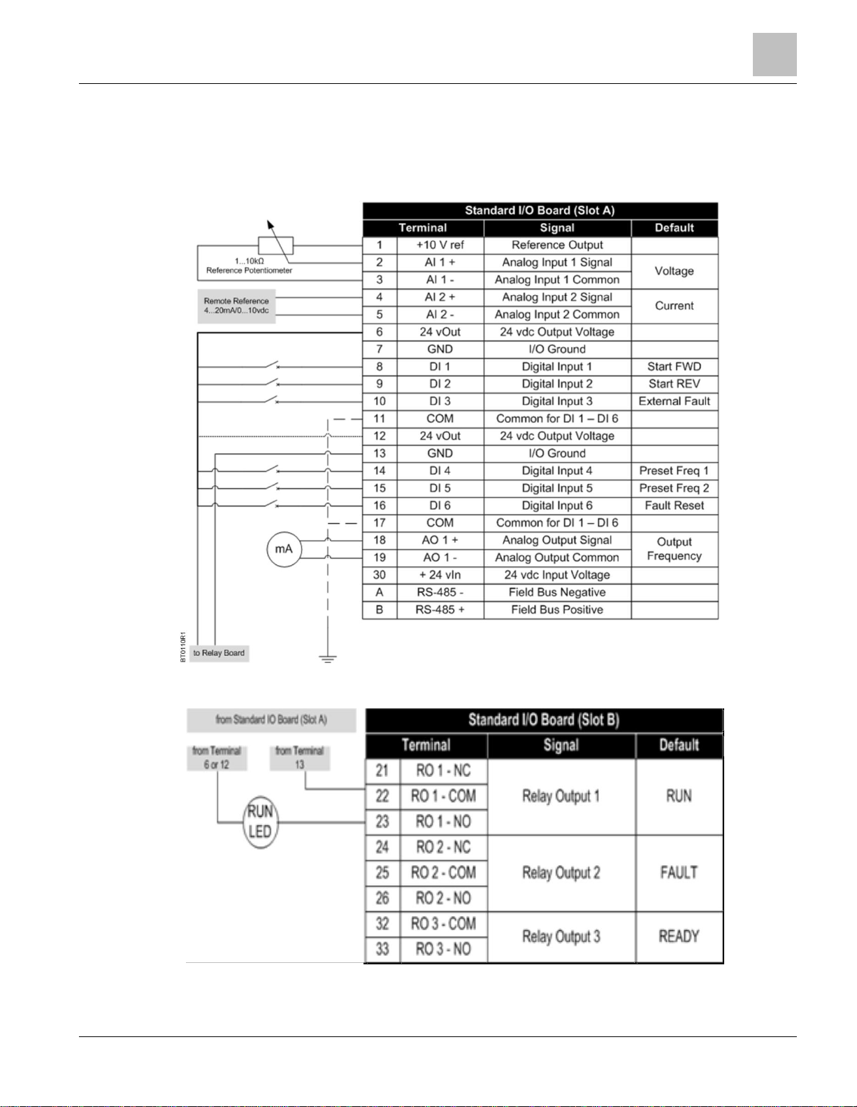
Chapter 2 - Control Board Terminal Connections
The control board terminals are located on the control module. The control module is identical for all sizes of the
BT300 HVAC Drive. It contains the keypad, terminals, and the control processor of the drive.
Connect the control wiring to the BT300 control terminals per the site-specific drawings.
Figure 3: Slot A Terminal Connections.
Figure 4: Slot B Terminal Connections.
Page 18
Chapter 2 - Control Board Terminal Connections
Analog Input Terminal Connections
18 | 180
Siemens Industry, Inc.
Siemens BT300 HVAC Drive
DPD01809
Building Technologies
2016-06-07
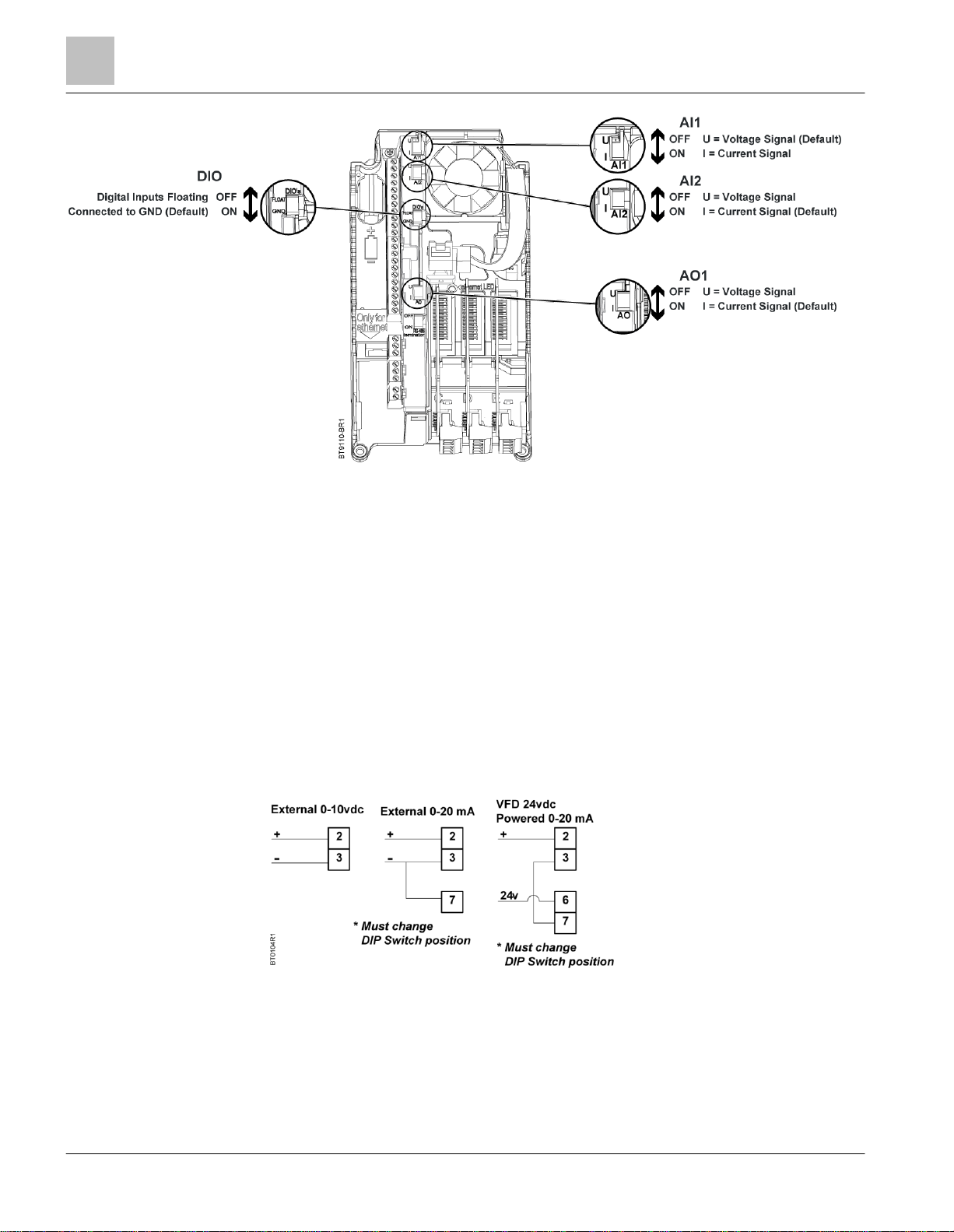
Figure 5: I/O-Related DIP Switches.
Analog Input Terminal Connections
The BT300 HVAC Drive consists of two analog inputs built on Slot A. When using analog inputs, the DIP switches
must be correctly set and the analog inputs correctly configured before enabling them.
When using an analog input for speed reference, the signal is automatically scaled for Minimum Frequency (P3.3.1)
to Maximum Frequency (P3.3.2) in accordance with the signal range (for example, on a 0 to 10 Vdc signal, 0V
represents Minimum Frequency and 10V represents Maximum Frequency). This scaling can be modified. See the
analog input parameters listed in
Analog Input 1
By default, Analog Input 1 is configured for a 0 to 10 Vdc signal source. The wiring is shown below. See Figure 5
for the location of the AI1 DIP switch. The DIP switch is set to the U (voltage) position at the factory. AI1 Signal
Range (P3.5.2.3) is used for programming the signal range of the analog input. Possible settings are 0 to 10 Vdc/0
to 20 mA or 2 to 10 Vdc/4 to 20 mA.
Chapter 3
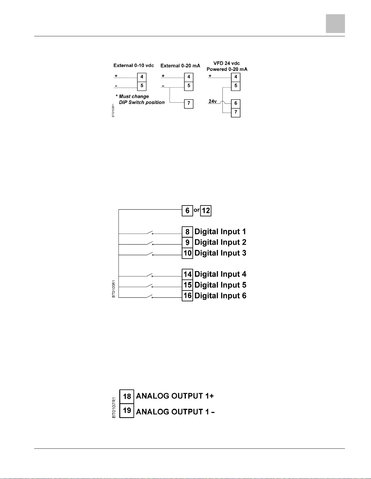
Figure 6: Analog Input 1 Terminal Connections.
.
Analog Input 2
By default, Analog Input 2 is configured for a 4 to 20 mA signal source. The wiring is shown below. See Figure 5
for the location of the AI2 DIP switch. The DIP switch is set to the I (current) position at the factory. AI2 Signal
Page 19
Chapter 2 - Control Board Terminal Connections
Digital Input Terminal Connections
19 | 180
Siemens Industry, Inc.
Siemens BT300 HVAC Drive
DPD01809
Building Technologies
2016-06-07
Range (P3.5.2.9) is used for programming the signal range of the analog input. Possible settings are 0 to 10 Vdc/0
to 20 mA or 2 to 10 Vdc/4 to 20 mA.
Figure 7: Analog Input 2 Terminal Connections.
Digital Input Terminal Connections
The BT300 HVAC Drive consists of six digital inputs built on Slot A. When using digital inputs, the DIP switch must
be correctly set and digital inputs correctly configured before enabling them.
Digital Inputs 1 through 6
See Figure 5 for the location of the DIO DIP switch. The DIP switch is set to the GND (Grounded) position at the
factory.
Figure 8: Digital Input Terminal Connections.
Analog Output Terminal Connections
The BT300 HVAC consists of one analog output built on Slot A. When using the analog output, the DIP switch
must be correctly set and the analog output correctly configured.
Analog Output 1
By default, Analog Output 1 is configured for a 4 to 20 mA signal. The wiring is shown below. See Figure 5 for the
location of the AO1 DIP switch. The DIP switch is set to the I (current) position at the factory.
Figure 9: Analog Output 1 Terminal Connections.
Page 20
Chapter 2 - Control Board Terminal Connections
Digital Output Terminal Connections
20 | 180
Siemens Industry, Inc.
Siemens BT300 HVAC Drive
DPD01809
Building Technologies
2016-06-07
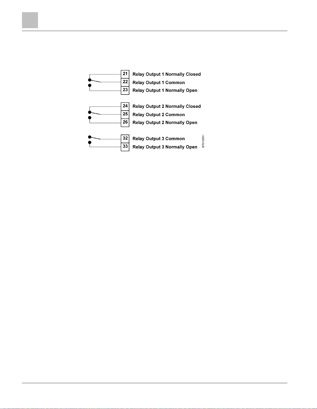
Digital Output Terminal Connections
The BT300 HVAC Drive consists of three digital (relay) outputs built on Slot B. See Figure 5 for the location of the
DIO DIP switch. When using the digital outputs, the DIP switch must be correctly set and digital outputs correctly
configured.
Figure 10: Digital Output Terminal Connections.
Page 21
Chapter 3 - Start-up Information
Procedure and Checklist
21 | 180
Siemens Industry, Inc.
Siemens BT300 HVAC Drive
DPD01809
Building Technologies
2016-06-07
There are several pre-checks that should be completed prior to powering up and commissioning the
BT300 HVAC Drive. See
the BT300 Startup Procedure and Checklist
(125-1006) for more details.
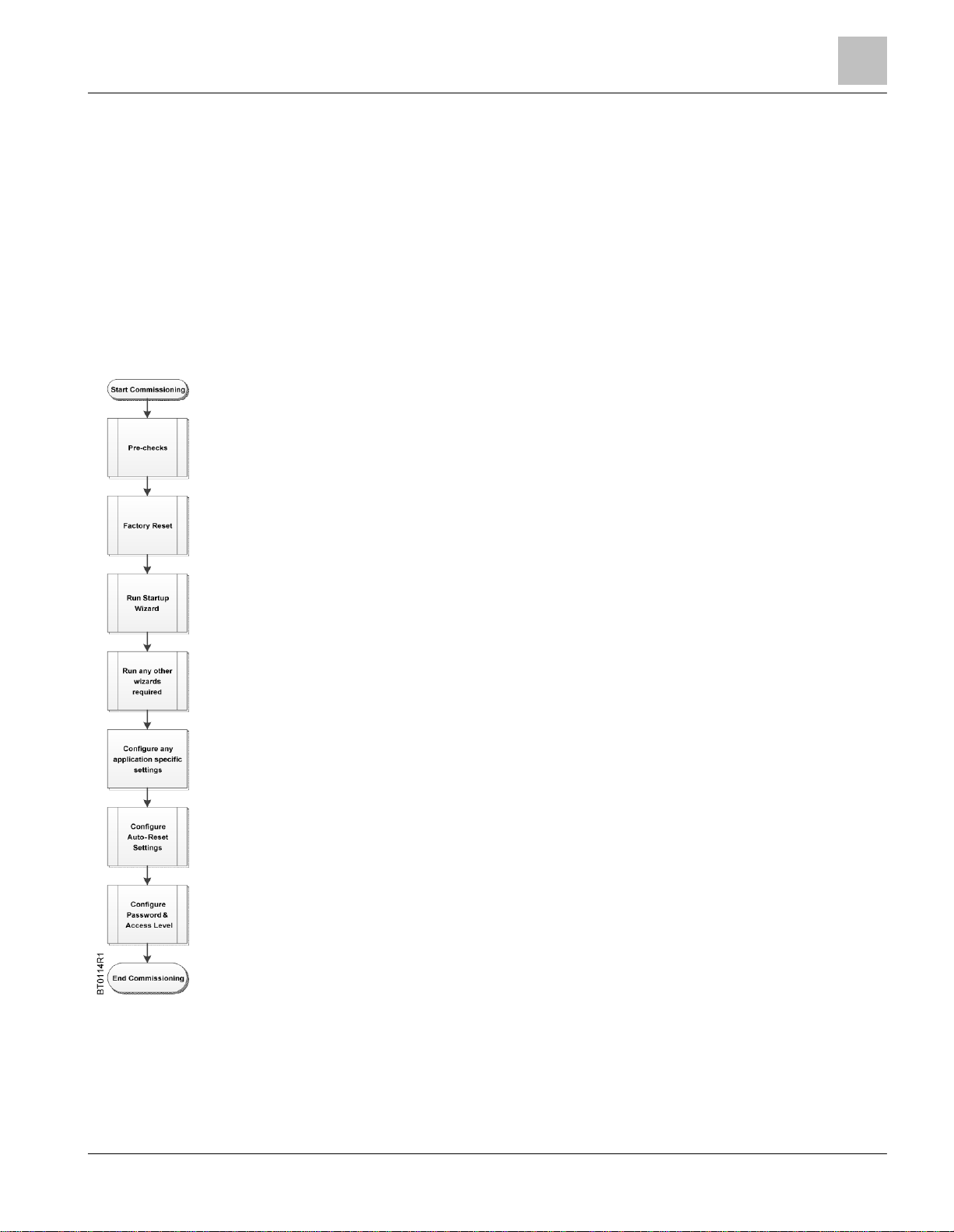
This step should be completed on all drives at start-up to ensure a good, known starting point. Select:
User Settings (M6) > Parameter Backup (M6.5) > Restore Factory Defaults (P6.5.1).
This step should be completed on all drives at start-up. This will be automatically started at the end of
the Factory Reset. Select: Quick Setup > Startup Wizard (P1.19), if necessary.
If any other wizards are needed, select one of the following:
Quick Setup > PID Mini-Wizard (M1.17) > Quick Setup/Multi-Pump Wizard (M1.20)
Quick Setup > Startup Wizard (M1.19) > Quick Setup/Fire Mode Wizard (M1.20)
Quick Setup > Bypass Wizard (M1.21)
Any other application-specific settings should be completed at this time.
Even if enabled during the Startup Wizard, the Auto-Reset should be configured for the site’s
requirements. There are several parameters to configure in this menu. Review all parameters.
Select: Parameters (M3) > Automatic Reset (M3.10)
This forces the Monitor, Favorites, and User Level menus only. This prevents unauthorized
parameterization through the keypad.
Select: User Levels (M8) > Access Code (P8.2). Set to desired access code (such as 4521).
User Levels (M8)/User Level (P8.1). Set to Monitoring.
To return to edit menus, select: User Levels (M8) > User Level (P8.1), and set to Normal. Enter the
Access code when prompted.
Chapter 3 - Start-up Information
Procedure and Checklist
To provide the most reliable drive available, and to avoid any extra costs related to loss or reduction of warranty
coverage, a factory-certified specialist should complete the startup procedures covered in the
and Checklist
(125-1006).
Commissioning Flowchart
Table 3: Commissioning Flowchart.
Startup Procedure
Page 22

Chapter 3 - Start-up Information
Wizards
22 | 180
Siemens Industry, Inc.
Siemens BT300 HVAC Drive
DPD01809
Building Technologies
2016-06-07
Step
Parameter/Question
Settings
1
Language Selections (P6.1)
Select the icon for the language you want applied to the keypad. This
varies depending upon the language package installed.
2
Daylight Saving (P5.5.5)
Select the Daylight Saving Rule
1 = Off
2 = EU
3 = US
4 = Russia
3
Time (P5.5.2)
Specify the current time of day in the following format: hh:mm:ss where
h = hour, m = minute, s = seconds.
4
Year (P5.5.4)
Specify the current year in the following format: yyyy where
yyyy = 4-digit year.
5
Date (P5.5.3)
Specify the current date in the following format: dd.mm where
dd = 2-digit day, mm = 2-digit month.
6
Startup Wizard?
Specify if the Startup Wizard should be activated: Yes, No
Step
Parameter/Question
Settings
7
Fan or Pump
(Application Type)
Pump
Automatically sets the following:
Accel Time 1 (P1.13) = 30
Decel Time 1 (P1.14) = 30
Start Function (P3.2.4) = Ramping
Stop Function (P3.2.5) = Ramping
Fan
Automatically sets the following:
Accel Time 1 (P1.13) = 120
Decel Time 1 (P1.14) = 120
Start Function (P3.2.4) = Flying Start
Stop Function (P3.2.5) = Coast to Stop
8
Motor Nom Voltg (P3.1.1.1)
Defines nominal motor voltage from motor nameplate data.
9
Motor Nom Freq (P3.1.1.2)
Defines nominal motor frequency from motor nameplate data.
Wizards
Wizards are available in the Quick Setup (M1) menu. The wizards assist you with various start-up and
commissioning functions. There are five wizards available in the BT300 HVAC Drive that prompt for essential
information needed for the following:
● Start-up Wizard - Easy commissioning of the drive.
● PID Mini-Wizard - Proper configuration of internal PID Loop Controller 1.
● Multi-Pump Wizard - Proper configuration of the Multi-pump application.
● Fire-Mode Wizard - Proper configuration of the Fire-mode.
● Bypass Wizard - Proper configuration of the bypass options (if connected).
Startup Wizard (P1.19)
The Startup Wizard prompts you for the essential information needed by the drive so that it can start controlling the
output as desired. Once power is connected to the BT300 HVAC Drive, the Startup Wizard should run
automatically. If it is not running, it can be activated in the Quick Setup (M1) menu or by completing Restore
Factory Defaults (P6.5.1)
The following steps are required to successfully complete the Startup Wizard:
If the option Yes is selected for Startup Wizard (recommended), you will be prompted for the following values:
Page 23

Chapter 3 - Start-up Information
Wizards
23 | 180
Siemens Industry, Inc.
Siemens BT300 HVAC Drive
DPD01809
Building Technologies
2016-06-07
Step
Parameter/Question
Settings
10
Motor Nom Speed (P3.1.1.3)
Defines nominal motor speed from motor nameplate data.
11
Motor Nom Currnt (P3.1.1.4)
Defines nominal motor current from motor nameplate data.
12
Motor Cos Phi (P3.1.1.5)
(Power Factor)
Defines nominal motor Cos Phi (power factor) from motor nameplate
data.
13
Motor Nom Power (P3.1.1.6)
Defines nominal motor power from motor nameplate data.
14
Min Frequency (P3.3.1)
Minimum allowed frequency reference.
15
Max Frequency (P3.3.2)
Maximum allowed frequency reference.
16
I/O Ctrl Ref (P3.3.3)
Selects location of frequency setpoint source when in I/O A control. In
the following list of possible settings, the main setpoint is selected:
1= Preset Freq 0
2 = Keypad Reference
3 = Fieldbus
4 = AI1
5 = AI2
6 = AI1+AI2
7 = PID 1 Reference
8 = Motor Potentiometer
17
Accel Time (P3.4.2)
Defines the time required to increase output frequency from 0 to Max
Frequency (P3.3.1).
18
Decel Time (P3.4.3)
Defines the time required to decrease output frequency from Max
Frequency (P3.3.1) to 0 frequency.
19
Ctrl Place Auto (P3.2.1)
Start/Stop commands are given differently depending upon the control
place. This parameter defines whether the Start/Stop command is
controlled by digital inputs as defined in Control Signal 1 A (P3.5.1.1)
and Control Signal 2 A (P3.5.1.2) in accordance with the I/O A
Start/Stop Logic (P3.2.6) or if the Start/Stop command is controlled by
the Fieldbus that is in use.
Settings:
0 = I/O Control (control is from the physical I/O, PID control, or time
channels)
1 = Fieldbus (control is from the configured fieldbus found in Ethernet
or RS-485 settings).
20
Automatic Reset (P3.10.1)
Determines if the Automatic Reset feature can be used.
21
Start Function (P3.2.4)
Defines the start function of the drive.
0 = Ramping Start
1 = Flying Start
22
Stop Function (P3.2.5)
Defines the stop function of the drive.
0 = Coast to Stop
1 = Ramping Stop
23
Motor Switch (P3.1.2.2)
Prevents the drive from tripping when a motor switch is located
between the drive and motor.
0 = No
1 = Yes
24
Bypass Wizard (P1.21)
Enable parameter for the Bypass Wizard. This wizard can be activated
during the Startup Wizard.
The Startup Wizard is now complete.
Page 24

Chapter 3 - Start-up Information
Wizards
24 | 180
Siemens Industry, Inc.
Siemens BT300 HVAC Drive
DPD01809
Building Technologies
2016-06-07
Step
Parameter/Question
Settings
1
Process unit selection (P3.12.1.4)
Several selections, see P3.12.1.4.
Step
Parameter/Question
Settings
2
Process Unit Min (P3.12.1.5)
Varies
3
Process Unit Max (P3.12.1.6)
Varies
4
Process Unit Decimals (P3.12.1.7)
Range: 0 to 4
5
Feedback 1 Source Selection (P3.12.3.3)
Several selections, see P3.12.3.3.
Step
Parameter/Question
Settings
6
Analog Input Signal Range
0 to 10V/0 to 20 mA
2 to 10V/4 to 20 mA
7
Error Inversion (P3.12.1.8)
Reverse Acting
Direct Acting
8
Setpoint Source Selection (P3.12.2.4)
Several selections, see P3.12.3.4.
Step
Parameter/Question
Settings
9
Analog Input Signal Range
0 to 10V/0 to 20 mA
2 to 10V/4 to 20 mA
10
Keypad SP1 (P3.12.2.1) or Keypad SP2
(P3.12.2.2)
Varies
11
Sleep Function?
No
Yes
Step
Parameter/Question
Settings
12
Sleep Frequency Limit 1 (P3.13.2.7)
Varies
13
Sleep Delay 1 (P3.12.2.8)
Varies
14
Wake-up Level 1 (P3.12.2.9)
Varies
PID Mini-Wizard (P1.17)
The PID Mini-Wizard is activated in the Quick Setup (M1) menu. This wizard will assist with configuring the drive
for use with the PID Controller 1 in a “one-feedback/one-setpoint” mode. The control place will be I/O A and the
default process unit is %.
The following steps are required to successfully complete the PID Mini-Wizard:
If a process unit other than % is selected, the following questions display. Otherwise, the wizard jumps directly to
Step 5:
If one of the analog input signals is selected, Step 6 displays. Otherwise, the wizard jumps directly to Step 7.
If one of the analog input signals is selected, Step 9 displays. If the either of the options Keypad SP1 or Keypad
SP2 is selected, then Step 10 displays. Otherwise, the wizard jumps directly to Step 11.
If the option Yes is selected for Sleep Function, you will be prompted for the sleep function settings:
The PID Mini-Wizard is now complete.
Page 25

Chapter 3 - Start-up Information
Wizards
25 | 180
Siemens Industry, Inc.
Siemens BT300 HVAC Drive
DPD01809
Building Technologies
2016-06-07
Step
Parameter/Question
Settings
1 – 14
Same as PID Mini-Wizard
15
Number of Motors (P3.14.1)
1 to 4
16
Interlock Function (P3.14.2)
Not Used
Enabled
17
Auto-change (P3.14.4)
Disabled
Enabled
Step
Parameter/Question
Settings
18
Include FC (P3.14.3)
Disabled
Enabled
19
Auto-change Interval (P3.14.5)
0.0 to 3000.0 h
20
Auto-change Frequency Limit (P3.14.6)
0.0 to 60.0 Hz
21
Bandwidth (P3.14.8)
0 to 100%
22
Bandwidth Delay (P3.14.9)
0 to 3600 s
NOTE:
The warranty is void if the Fire Mode function is activated. Test Mode can be used to
test the Fire Mode function without voiding the warranty. Read important information
about the password and warranty issues in Chapter 4 before you proceed.
Multi-Pump Wizard (P1.18)
The Multi-Pump Wizard is activated in the Quick Setup (M1) menu. This wizard assists with configuring the drive for
use with PID Controller 1, and then asks the most important questions for setting up a multi-pump system.
The following steps are required to successfully complete the Multi-Pump Wizard:
If the Auto-change function is enabled, the following will display. Otherwise, the wizard jumps directly to Step 21:
After this, the keypad displays the digital input and relay output configuration done by the application. It is
recommended that these values are written down for future reference.
The Multi-Pump Wizard is now complete.
Fire Mode Wizard (P1.20)
The Fire Mode feature of the drive is designed to place the drive in a mode that ignores all commands from the
keypad, fieldbuses, and the personal computer tool. In addition, the drive will ignore all alarms and faults of the
drive and continue providing frequency to the attached motor. This is designed for instances when the destruction of
equipment is better than loss of life. The Fire Mode feature can be operated so that the PID loop is still in control of
the attached motor. The Fire Mode Wizard allows for easy commissioning of the Fire Mode function.
The Fire Mode Wizard is activated in the Quick Setup (M1) menu. The wizard assists with configuring the drive for
use with the Fire Mode feature.
Test Mode can be used to test the Fire Mode function without voiding the warranty.
The Fire Mode Wizard can be initiated by choosing Activate for Fire Mode Wizard (P1.20) in the Quick Setup (M1)
Menu.
The following steps are required to successfully complete the Fire-Mode Wizard:
Page 26

Chapter 3 - Start-up Information
Wizards
26 | 180
Siemens Industry, Inc.
Siemens BT300 HVAC Drive
DPD01809
Building Technologies
2016-06-07
Step
Parameter/Question
Settings
1
Fire Mode Frequency Source (P3.16.5)
Several selections; see P3.16.5.
Step
Parameter/Question
Settings
2
Fire Mode Frequency (P3.16.4)
Range: 0 to Maximum Frequency (P1.9)
3
Signal Activation?
Open Contact
Closed Contact
4
Fire Mode Activation Open (P3.16.2)
Or
Fire Mode Activation Close (P3.16.3)
Choose the digital input to activate Fire Mode.
5
Fire Mode Reverse (P3.16.6)
Choose the digital input to activate the reverse command in
Fire Mode.
DigIN Slot0.1 = FORWARD
DigIN Slot0.2 = REVERSE
6
Fire Mode Password (P3.16.1)
Choose the password to enable the Fire Mode Function.:
1234 = Test Mode
1002 = Enable Fire Mode
Step
Parameter/Question
Settings
1
Select the Bypass (P3.17.4) mode
Electronic
Conventional
Disabled
If Fire Mode Frequency is selected, the following will display. Otherwise, the wizard jumps directly to Step 3:
The Fire Mode Wizard is now complete.
Bypass Wizard (P1.21)
The Bypass Wizard is activated in the Quick Setup (M1) menu. The wizard assists with configuring the drive for use
with the Conventional or Electronic Bypass options. If the Electronic Bypass option is selected, additional features
can be enabled, if desired. The standard I/O is re-mapped for use with the Electronic Bypass option. Additional
parameters are available when the Electronic Bypass option is enabled.
The following steps are required to successfully complete the Bypass Wizard:
If Conventional is selected, the following changes occur automatically, the wizard completes, and the message:
Bypass Wizard is now complete. Press OK to continue. displays.
● Control Signal 2 A (P3.5.1.2) is set to DigIN Slot0.1 to disable the reverse command on Digital Input 2.
● Run Interlock 2 (P3.5.1.13) is set to DigIN SlotA.2 to enable the run interlock on Digital Input 2. The status of
the Output Contactor (M2) is factory-wired to digital input 2.
● Preset Freq Sel0 (P3.5.1.15) is set to DigIN Slot0.1 to disable the Preset Frequency Selection 0 on Digital Input
4.
● Overload (P3.5.1.53) is set to DigIN SlotA.5 to enable the overload on Digital Input 5. The status of the
Overload is factory-wired to Digital Input 5.
If Electronic is selected, the following change occurs automatically:
Overload (P3.5.1.53) is set to DigIN SlotA.5 to enable the overload on Digital Input 5. The status of the Overload is
factory-wired to Digital Input 5.
The wizard continues with the following steps:
Page 27

Chapter 3 - Start-up Information
Wizards
27 | 180
Siemens Industry, Inc.
Siemens BT300 HVAC Drive
DPD01809
Building Technologies
2016-06-07
Step
Parameter/Question
Settings
2
Bypass Delay (P3.18.1) Time
Defines the amount of time between the unit being
placed into Bypass mode and the M1 contactor closing.
Range: 1 to 30 s
3
Essential Services* (P3.18.5)
Enabled
Disabled
Step
Parameter/Question
Settings
4
Essential Services Activation (P3.5.1.52)
DigIN SlotA.6
5
Remote Bypass* (P3.18.6)
Enabled
Disabled
Step
Parameter/Question
Settings
6
Command Source (P3.5.1.1)
Fieldbus CTRL
I/O Control
7
Interlock* (P3.2.11)
Enabled
Disabled
Step
Parameter/Question
Settings
8
Interlock Delay (P3.2.12)
Range: 0 to 120 s
9
Auto Bypass* (P3.18.2)
Enabled
Disabled
Step
Parameter/Question
Settings
10
Auto Bypass Delay (P3.18.4)
Range: 0 to 30 s
11
Fault Selection (P3.18.3)
Select faults to enable auto Bypass:
Any Fault
Undervoltage
Overvoltage
Overcurrent
AI Low
Unit Temperature
Motor Overtemp
External Fault
Underload Fault
If Enabled is selected for Essential Services, Step 4 displays. Otherwise, the wizard jumps directly to Step 5.
If Enabled is selected for Remote Bypass, Step 6 displays. Otherwise, the wizard jumps directly to Step 7.
If Enabled is selected for Interlock, Step 8 displays. Otherwise, the wizard jumps directly to Step 9.
If Enabled is selected for Auto Bypass, Step 10 displays. Otherwise, the wizard jumps directly to Step 11.
* Feature of the Electronic Bypass Option. For more details, see
The Bypass Wizard is now complete. The following message displays: Bypass Wizard is now complete.
Press OK to continue.
If Disabled is selected, no changes occur and the wizard completes The following message displays: Bypass
Wizard is now complete. Press OK to continue.
For more information on the bypass options, see the
Instructions
(DPD01375) and the
BT300 Bypass Operator’s Manual
BT300 Variable Frequency Drive Bypass Installation
BT300 Variable Frequency Drive Bypass Operator’s Manual
(DPD01391)
(DPD01391).
Page 28

Chapter 4 - Parameters and Menu Structure
Wizards
28 | 180
Siemens Industry, Inc.
Siemens BT300 HVAC Drive
DPD01809
Building Technologies
2016-06-07
Quick Setup (M1)
All basic parameters
required to quickly setup
the BT300 VFD for
operation and all available
wizards.
P1.17 PID Mini-Wizard
Diagnostics (M4)
Diagnostics information such
as active faults, fault history
and counters.
M4.1 Active Faults
P1.18 Multi-Pump Wizard
M4.2 Reset Faults
P1.19 Startup Wizard
M4.3 Fault History
P1.20 Fire Mode Wizard
M4.4 Total Counters
P1.21 Bypass Wizard
M4.5 Trip Counters
Monitor (M2)
Access to the Multimonitor display and
parameters used for
monitoring.
M2.1 Multimonitor
M4.6 Software Info
M2.2 Basic
I/O and Hardware (M5)
Parameters for status of I/O,
real time clock, keypad, and
fieldbus configuration.
M5.1 Basic IO
M2.3 Timer Functions
M5.2 Slot C
M2.4 PID Controller 1
M5.3 Slot D
M2.5 PID Controller 2
M5.4 Slot E
M2.6 Multi-Pump
M5.5 Real Time Clock
M2.8 Fieldbus Data
M5.6 Power Unit Settings
M2.9 Temp. Inputs
M5.7 Keypad
Parameters (M3)
Parameters used for
basic and advanced
configuration
requirements.
M3.1 Motor Settings
M5.8 RS-485
M3.2 Start/Stop Setup
M5.8.1 Common Settings
M3.3 References
M5.8.3 BACnet MSTP1
M3.4 Ramps and Brakes
M5.8.3 Modbus RTU1
M3.5 I/O Config
M5.8.3 N21
M3.5.1 Digital Inputs
M5.8.3 P11
M3.5.2 Analog Inputs
M5.9 Ethernet
M3.5.3 Digital Outputs
M5.9.1 Common Settings
M3.5.4 Analog Outputs
M5.9.2 Modbus TCP
M3.6 Fieldbus DataMap
M5.9.3 BACnet IP
M3.7 Prohibit Freq
User Settings (M6)
User information such as
keypad language selection,
parameter backup/restore, and
drive name.
M6.1 Language Selection
M3.8 Limit Superv
M6.5 Parameter Backup
M3.9 Protections
M6.6 Parameter Compare
M3.10 Automatic Reset
M6.7 Drive Name
M3.11 Timer Function
Favorites (M7)
List of user-defined parameter
list.
M3.12 PID Controller 1
M3.13 PID Controller 2
M3.14 Multi-Pump
User Levels (M8)
Restricts the visibility of
parameters
P8.1 User Level
M3.16 Fire Mode
P8.2 Access Code
M3.17 Appl. Setttings
M3.18 Bypass2
1 Displayed based on value of Protocol (P5.8.1.1)
2 Displayed based on value of Bypass (P3.17.4)
Chapter 4 - Parameters and Menu Structure
All information and parameters are organized in a menu structure:
Page 29

Chapter 4 - Parameters and Menu Structure
Quick Setup (M1)
29 | 180
Siemens Industry, Inc.
Siemens BT300 HVAC Drive
DPD01809
Building Technologies
2016-06-07
Structure
Parameter
Unit
ID
Description
P1.1
Motor Nom Voltg
V
110
Defines nominal motor voltage from motor nameplate data.
Also see
Menu Structure P3.1.1.1
.
P1.2
Motor Nom Freq
Hz
111
Defines nominal motor frequency from motor nameplate data.
Also see
Menu Structure P3.1.1.2.
P1.3
Motor Nom Speed
rpm
112
Defines nominal motor speed from motor nameplate data.
Also see
Menu Structure P3.1.1.3
.
P1.4
Motor Nom Currnt
A
113
Defines nominal motor current from motor nameplate data.
Also see
Menu Structure P3.1.1.4
.
P1.5
Motor Cos Phi
120
Defines nominal motor Cos Phi (power factor) from motor nameplate data.
Also see
Menu Structure P3.1.1.5
.
P1.6
Motor Nom Power
hp
116
Defines nominal motor power from motor nameplate data.
Also see
Menu Structure P3.1.1.6.
P1.7
Current Limit
A
107
Defines maximum current limit for motor. Suggested to use Motor Nominal
Current (P1.4) multiplied by motor service factor from motor nameplate data.
Also see
Menu Structure P3.1.1.7.
P1.8
Min Frequency
Hz
101
Sets minimum motor frequency at which motor will run irrespective of
frequency setpoint.
Also see
Menu Structure P3.3.1.
P1.9
Max Frequency
Hz
102
Sets maximum motor frequency at which motor will run irrespective of
frequency setpoint.
Also see
Menu Structure P3.3.2.
P1.10
I/O A Ctrl Ref
117
Selects location of frequency setpoint source when in I/O A control. In the
following list of possible settings, the main setpoint is selected:
1= Preset Freq 0
2 = Keypad Reference
3 = Fieldbus
4 = AI1
5 = AI2
6 = AI1+AI2
7 = PID 1 Reference
8 = Motor Potentiometer
Also see
Menu Structure P3.3.3.
P1.11
Preset Freq 1
Hz
105
Used according to state of digital input defined for Preset Frequency
Selection 1 (P3.5.1.16). Decoding mode chosen with Preset Frequency Mode
(P3.3.10). Also see
Menu Structure P3.3.12
.
P1.12
Preset Freq 2
Hz
106
Used according to state of digital inputs Preset Frequency Selection 2
(P3.5.1.17). Decoding mode chosen with Preset Frequency Mode (P3.3.10).
Also see
Menu Structure P3.3.13
.
P1.13
Accel Time 1
s
103
Time allowed for motor to accelerate from a standstill (0) up to Maximum
Frequency (P1.9).
This parameter can also be found in Menu Structure P3.4.2
P1.14
Decel Time 1
s
104
Time allowed for motor to decelerate from Maximum Frequency (P1.9) to a
standstill (0). Also see
Menu Structure P3.4.3
.
Quick Setup (M1)
The Quick Setup parameter group is a collection of parameters that are the most commonly used during installation
and commissioning. They are collected in the first parameter group so that they can be found quickly and easily.
However, they can be also be reached and edited in the actual parameter groups. Changing a parameter value in
the Quick Setup group also changes the value of this parameter in its actual group.
The Quick Setup parameters are presented in the following table:
Table 4: Quick Setup Parameters.
Page 30

Chapter 4 - Parameters and Menu Structure
Monitor Menu (M2)
30 | 180
Siemens Industry, Inc.
Siemens BT300 HVAC Drive
DPD01809
Building Technologies
2016-06-07
Structure
Parameter
Unit
ID
Description
P1.15
Ctrl. Place Auto
172
Start/Stop commands are given differently depending upon the control place.
This parameter defines whether the Start/Stop command is controlled by
digital inputs as defined in Control Signal 1 A (P3.5.1.1) and Control Signal 2
A (P3.5.1.2) in accordance with the I/O A Start/Stop Logic (P3.2.6) or if the
Start/Stop command is controlled by the Fieldbus that is in use.
Settings:
0 = I/O Control (control is from the physical I/O, PID control, or time channels)
1 = Fieldbus (control is from the configured fieldbus found in Ethernet or RS485 settings)
Also see
Menu Structure P3.2.1
.
P1.16
Automatic Reset
731
Enable parameter for the Automatic Reset function of the drive. This feature
is configured in the Parameters (M3) … Automatic Reset (M3.10) menu.
Also see
Menu Structure P3.10.1
.
P1.17
PID Mini-Wizard
1803
Enable parameter for the PID Mini-Wizard. This wizard assists with the
configuration of the PID Controller 1 using a single feedback and single
setpoint.
P1.18
MultiPump Wizard
Enable parameter for the Multi-Pump Wizard. This wizard assists with the
configuration of the Multi-Pump function of the drive. The PID Mini Wizard will
precede this wizard.
P1.19
Startup Wizard
1171
Enable parameter for the Startup Wizard. This wizard assist with the essential
information required for drive operation.
This wizard is automatically enabled after Restore Factory Defaults (P6.5.1) is
activated.
P1.20
Fire Mode Wizard
1672
Enable parameter for the Fire Mode Wizard.
P1.21
Bypass Wizard
1823
Enable parameter for the Bypass Wizard. This wizard can be activated during
the Startup Wizard.
Menu and Parameter Group
Description
Multimonitor (M2.1)
Display of 9 monitored values.
Basic (M2.2)
Display of basic drive monitoring parameters.
Timer Functions (M2.3)
Display of timer function specific monitoring parameters.
PID Controller 1 (M2.4)
Display of PID Controller 1 specific monitoring parameters.
PID Controller 2 (M2.5)
Display of PID Controller 2 specific monitoring parameters.
Multi-Pump (M2.6)
Display of Multi-Pump specific monitoring parameters.
Fieldbus Data (M2.8)
Display of Mapped Fieldbus Data monitoring parameters.
Temp. Inputs (M2.9)
Display of connected temperature inputs.
Monitor Menu (M2)
The Siemens BT300 HVAC Drive allows you to monitor actual values, parameters, and signals as well as status
and measurements. Some of the monitored values are customizable.
Multimonitor (M2.1)
On the Multi-Monitor page, you can collect nine values to monitor. The display fields can be changed by selecting
the display field to be changed with the and arrow buttons, and then pressing the button. Scroll
Table 5: Monitor Menu.
Page 31

Chapter 4 - Parameters and Menu Structure
Monitor Menu (M2)
31 | 180
Siemens Industry, Inc.
Siemens BT300 HVAC Drive
DPD01809
Building Technologies
2016-06-07
NOTE:
Only Standard I/O board statuses are available in the Monitor menu. Statuses for all
I/O board signals can be found as raw data in the I/O and Hardware (M5) menu.
Structure
Parameter
Unit
ID
Description
M2.2.1
Output Frequency
Hz 1 Displays the actual output frequency.
M2.2.2
FreqReference
Hz
25
Displays the actual frequency reference (setpoint).
M2.2.3
Motor Speed
rpm 2 Displays the actual motor speed.
M2.2.4
Motor Current
A 3 Displays the actual motor current.
M2.2.5
Motor Torque
% 4 Displays the calculated motor torque.
M2.2.7
Motor Power
% 5 Total power consumption of the drive in %
M2.2.8
Motor Power
hp
73
Total power consumption of the drive in kW or hp
M2.2.9
Motor Voltage
V 6 Voltage feed to the motor
M2.2.10
DC-Link Voltage
V 7 Voltage available on the DC Link
M2.2.11
Unit Temperature
ºF 8 Heat sink temperature
M2.2.12
MotorTemperature
% 9 Calculated motor temperature
M2.2.13
Analog Input 1
%
59
Signal of used range in %
M2.2.14
Analog Input 2
%
60
Signal of used range in %
M2.2.15
Analog Output 1
%
81
Signal of used range in %
M2.2.16
Motor PreHeat
1228
0 = Off
1 = Heating (feeding DC current)
M2.2.17
DriveStatusWord
43
Bit coded status of the drive
B1 = Ready
B2 = Run
B3 = Fault
B6 = Run Enable
B7 = Alarm Active
B10 = DC Current (in stop)
B11 = DC Brake Active
B12 = Run Request
B13 = Motor Regulator Active
M2.2.18
Last ActiveFault
37
Fault code of last activated fault that has not been reset.
See Fault Codes
.
through the list of items until the desired value to be monitored is highlighted. Items with a checkmark are already
actively displayed in the multimonitor display. With an item chosen, press the button again to add to the
display field.
Basic (M2.2)
The basic monitoring values are the actual values of selected parameters and signals as well as statuses and
measurements. Different applications may have different statuses and different numbers of monitoring values.
The basic monitoring values are presented in the following table:
Table 6: Monitoring Menu Items.
Page 32

Chapter 4 - Parameters and Menu Structure
Monitor Menu (M2)
32 | 180
Siemens Industry, Inc.
Siemens BT300 HVAC Drive
DPD01809
Building Technologies
2016-06-07
Structure
Parameter
Unit
ID
Description
M2.2.19
FireMode Status
1597
0 = Disabled
1 = Enabled
2 = Activated (Enabled & DI)
3 = Test Mode
M2.2.20
DIN StatusWord1
56
B0 = SlotA.1…B5 = SlotA.6
B6 = SlotB.1…B11 = SlotB.6
B12 = SlotC.1…B15 = SlotC.4
M2.2.21
DIN StatusWord2
57
B0 = SlotC.5…B1 = SlotC.6
B2 = SlotD.1…B7 = SlotD.6
B8 = SlotE.1…B13 = SlotE.4
M2.2.22
MotCurrent1Deci.
45
Motor current monitor value with fixed number of decimals and less filtering. For
example, can be used for fieldbus purpose to always get the right value
regardless of frame size, or monitoring when less filtering time is needed for
motor current.
M2.2.23
Appl.StatusWord1
89
Bit coded application status word 1
B0 = Interlock1
B1 = Interlock2
B5 = I/O A Control Active
B6 = I/O B Control Active
B7 = Fieldbus Control Active
B8 = Hand Control Active
B9 = PC Control Active
B10 = Preset Freq Active
B12 = FireMode Active
B13 = PreHeat Active
M2.2.24
Appl.StatusWord2
90
Bit coded application status word 2
B0 = Acc/Dec Prohibited
B1 = MotorSwitch Active
M2.2.25
kWhTripCounter Low
1054
Energy counter with kWh output (low word)
M2.2.26
kWhTripCounter High
1067
# of times energy counter has spun around (high word)
M2.2.27
Appl.StatusWord3
1851
Bit coded application status word 3
M2.2.28
Safety StatusWord
1852
Bit coded Safety Status Word
M2.2.29
Bypass Runtime
h
1850
Bypass Running Hours
Structure
Parameter
Unit
ID
Description
M2.3.1
TC 1, TC 2, TC 3
1441
Status of the three time channels
M2.3.2
Interval 1
1442
Status of timer interval
M2.3.3
Interval 2
1443
Status of timer interval
M2.3.4
Interval 3
1444
Status of timer interval
M2.3.5
Interval 4
1445
Status of timer interval
M2.3.6
Interval 5
1446
Status of timer interval
Timer functions monitoring (M2.3)
The timer functions monitoring values and the actual values of the timer functions and the real time clock. See
Timer Functions (M3.11).
Table 7: Monitoring of Timer Functions.
Page 33

Chapter 4 - Parameters and Menu Structure
Monitor Menu (M2)
33 | 180
Siemens Industry, Inc.
Siemens BT300 HVAC Drive
DPD01809
Building Technologies
2016-06-07
Structure
Parameter
Unit
ID
Description
M2.3.7
Timer 1
s
1447
Remaining time on timer (if active)
M2.3.8
Timer 2
s
1448
Remaining time on timer (if active)
M2.3.9
Timer 3
s
1449
Remaining time on timer (if active)
M2.3.10
Real Time Clock
1450
Current Time of Day
Structure
Parameter
Unit
ID
Description
M2.4.1
PID1 Setpoint
Varies
20
Setpoint for the PID controller for the attached motor
M2.4.2
PID1 Feedback
Varies
21
Feedback for the PID controller for the attached motor
M2.4.3
PID1 Error
Varies
22
Error value of the PID controller for the attached motor
M2.4.4
PID1 Output
%
23
Output of the PID controller for the attached motor
M2.4.5
PID1 Status
24
0 = Stopped
1 = Running
3 = Sleep Mode
4 = In dead band
Structure
Parameter
Unit
ID
Description
M2.5.1
PID2 Setpoint
Varies
83
Setpoint for the PID controller for the external device (AO)
M2.5.2
PID2 Feedback
Varies
84
Feedback for the PID controller for the external device (AO)
M2.5.3
PID2 Error
Varies
85
Error value of the PID controller for the external device (AO)
M2.5.4
PID2 Output
%
86
Output of the PID controller for the external device (AO)
M2.5.5
PID2 Status
87
0 = Stopped
1 = Running
4 = In dead band
PID Controller 1 Monitoring (M2.4)
The PID Controller 1 monitoring values are the actual values of the first PID controller, which is used to control the
speed of the motor that is physically connected to the drive’s output. See
The PID Controller 1 monitoring values are presented in the following table:
Table 8: PID1-Controller Value Monitoring.
PID Controller 1 (M3.12).
PID Controller 2 Monitoring (M2.5)
The PID Controller 2 monitoring values are the actual values of the second PID controller, which is used for external
devices that require PID loop control. See
PID Controller 2 (M3.13).
The PID Controller 2 monitoring values are presented in the following table:
Table 9: PID2-Controller Value Monitoring.
Multi-pump monitoring (M2.6)
The Multi-Pump monitoring values are the actual values related to the use of several drives/motors. See
(M3.14).
The Multi-Pump monitoring values are presented in the following table:
Multi-Pump
Page 34

Chapter 4 - Parameters and Menu Structure
Monitor Menu (M2)
34 | 180
Siemens Industry, Inc.
Siemens BT300 HVAC Drive
DPD01809
Building Technologies
2016-06-07
Structure
Parameter
Unit
ID
Description
M2.6.1
Motors Running
30
The number of motors running at the moment when Multi-Pump functionality is used.
M2.6.2
Autochange
1114
If an autochange is requested,
requested
means that the autochange time has elapsed
and the drive is waiting until the rest of the autochange criteria is fulfilled. For example,
output frequency of controlled drive and number of running motors.
Structure
Parameter
Unit
ID
Description
M2.8.1
FB Control Word
874
Fieldbus control word used by application in bypass mode/format. Depending on the
fieldbus type or profile the data might be modified before sent to the application.
M2.8.2
FB Speed Reference
Hz
875
Speed reference scaled between minimum and maximum frequency at the moment it
was received to the application. Minimum and maximum frequency might have been
changed after the reference was received without affecting the reference.
M2.8.3
FB Data In 1
876
Raw value of process data in 32-bit signed format.
M2.8.4
FB Data In 2
877
Raw value of process data in 32-bit signed format.
M2.8.5
FB Data In 3
878
Raw value of process data in 32-bit signed format.
M2.8.6
FB Data In 4
879
Raw value of process data in 32-bit signed format.
M2.8.7
FB Data In 5
880
Raw value of process data in 32-bit signed format.
M2.8.8
FB Data In 6
881
Raw value of process data in 32-bit signed format.
M2.8.9
FB Data In 7
882
Raw value of process data in 32-bit signed format.
M2.8.10
FB Data In 8
883
Raw value of process data in 32-bit signed format.
M2.8.11
FB Status Word
864
Fieldbus status word sent by application in bypass mode/format. Depending on the
fieldbus type or profile the data might be modified before sent to the fieldbus.
M2.8.12
FB Speed Actual
%
865
Actual speed in %. 0 and 100% corresponds to minimum and maximum frequency
respectively. This is continuously updated depending on the momentary min and max
frequency and output frequency.
M2.8.13
FB Data Out 1
866
Raw value of process data out 32-bit signed format.
M2.8.14
FB Data Out 2
867
Raw value of process data out 32-bit signed format.
M2.8.15
FB Data Out 3
868
Raw value of process data out 32-bit signed format.
M2.8.16
FB Data Out 4
869
Raw value of process data out 32-bit signed format.
M2.8.17
FB Data Out 5
870
Raw value of process data out 32-bit signed format.
M2.8.18
FB Data Out 6
871
Raw value of process data out 32-bit signed format.
M2.8.19
FB Data Out 7
872
Raw value of process data out 32-bit signed format.
M2.8.20
FB Data Out 8
873
Raw value of process data out 32-bit signed format.
Table 10: Multi-Pump Monitoring.
Fieldbus data monitoring (M2.8)
The Fieldbus Data monitoring values are shown for debugging purposes. See
The Fieldbus Data monitoring values are presented in the following table:
Table 11: Fieldbus Data Monitoring.
Fieldbus Data Mapping (M3.6).
Page 35

Chapter 4 - Parameters and Menu Structure
Parameters (M3)
35 | 180
Siemens Industry, Inc.
Siemens BT300 HVAC Drive
DPD01809
Building Technologies
2016-06-07
Structure
Parameter
Unit
ID
Description
M2.9.1
Temp Input 1
ºF
50
Measured value of temperature input 1.
M2.9.2
Temp Input 2
ºF
51
Measured value of temperature input 2.
M2.9.3
Temp Input 3
ºF
52
Measured value of temperature input 3.
Menu and Parameter group
Description
Motor Settings (M3.1)
Basic and advanced motor settings.
Start/Stop Setup (M3.2)
Start and stop functions.
References (M3.3)
Frequency references setup.
Ramps and Brakes (M3.4)
Acceleration and deceleration setup.
I/O Config (M3.5)
Input/Output (I/O) configuration.
Fieldbus DataMap (M3.6)
Fieldbus data out setup.
Prohibited Freq (3.7)
Prohibited frequencies setup.
Limit Superv (M3.8)
Programmable limit controllers.
Protections (M3.9)
Protections configuration.
Automatic Reset (M3.10)
Automatic reset after fault setup.
Timer Functions (M3.11)
Setup of time of day operation based on real time clock.
PID Controller 1 (M3.12)
Configuration of PID Controller 1. Used for motor control or external usage.
PID Controller 2 (M3.13)
Configuration of PID Controller 2. Used for external usage.
Multi-Pump (M3.14)
Configuration for multi-pump usage.
Fire Mode (M3.16)
Configuration for fire mode usage.
Appl. Settings (M3.17)
Parameters for regional settings and application.
ByPass (M3.18)
Parameters for Electronic Bypass option (when used).
Temperature inputs monitoring (M2.9)
The Temperature Inputs monitoring values are the actual values of the temperature inputs connected using slot C,
D, or E. If no sensor is available, the monitoring values do not exist.
The Temperature Inputs monitoring values are presented in the following table:
Table 12: Temperature Inputs Monitoring.
Parameters (M3)
The Parameters group is a collection of parameters that are used during installation and commissioning. The
parameters group is used for configuration of the application in better detail than the Startup Wizard alone.
The parameters menu and application contain the following parameter groups:
Table 13: Parameter Groups.
Motor Settings (M3.1)
This structure contains basic (such as motor nameplate data) and advanced (such as pre-heat function) motor
settings.
Page 36

Chapter 4 - Parameters and Menu Structure
Parameters (M3)
36 | 180
Siemens Industry, Inc.
Siemens BT300 HVAC Drive
DPD01809
Building Technologies
2016-06-07
Structure
Parameter
Unit
Min
Max
Default
ID
Description
P3.1.1.1
Motor Nom Voltg
V
Varies
Varies
Varies
110
Defines nominal motor voltage from
motor nameplate data.
Also see
Menu Structure P1.1.
P3.1.1.2
Motor Nom Freq
Hz 8 320
60
111
Defines nominal motor frequency
from motor nameplate data. Also
see
Menu Structure P1.2.
P3.1.1.3
Motor Nom Speed
rpm
24
19200
Varies
112
Defines nominal motor speed from
motor nameplate data. Also see
Menu Structure P1.3.
P3.1.1.4
Motor Nom Currnt
A
Varies
Varies
Varies
113
Defines nominal motor current from
motor nameplate data. Also see
Menu Structure P1.4.
P3.1.1.5
Motor Cos Phi
0.3 1 Varies
120
Defines nominal motor Cos Phi
(power factor) from motor
nameplate data. Also see
Menu
Structure P1.5.
P3.1.1.6
Motor Nom Power
hp
Varies
Varies
Varies
116
Defines nominal motor power from
motor nameplate data. Also see
Menu Structure P1.6.
P3.1.1.7
Current Limit
A
Varies
Varies
Varies
107
Defines maximum current limit for
motor. Suggested to use Motor
Nominal Current (P3.1.1.4)
multiplied by motor service factor
from motor nameplate data. Also
see
Menu Structure P1.7.
P3.1.1.8
Motor Type
IM
PMM
IM
650
Selection of the motor type as
follows:
0 = IM = Asynchronous Induction
Motor
1 = PMM = PM Synchronous Motor
Structure
Parameter
Unit
Min
Max
Default
ID
Description
P3.1.2.1
Switching Freq
kHz
1.5
Varies
Varies
601
Motor noise can be minimized using a
high switching frequency. Increasing the
switching frequency reduces the
capacity of the drive. It is recommended
to use a lower frequency when the motor
cable is long in order to minimize
capacitive currents in the cable.
P3.1.2.2
Motor Switch
No
Yes
No
653
Prevents the drive from tripping when a
motor switch is located between the
drive and motor.
0 = No
1 = Yes
P3.1.2.4
Zero Freq Voltg
% 0 40
Varies
606
Defines the zero frequency voltage of
the U/f curve.
Basic Settings (M3.1.1)
Table 14: Basic Motor Settings.
Motor Control Settings (M3.1.2)
Table 15: Motor Control Settings.
Page 37

Chapter 4 - Parameters and Menu Structure
Parameters (M3)
37 | 180
Siemens Industry, Inc.
Siemens BT300 HVAC Drive
DPD01809
Building Technologies
2016-06-07
Structure
Parameter
Unit
Min
Max
Default
ID
Description
P3.1.2.5
Preheat Function
Not Used
Temp Limit
Not Used
1225
Defines the use of the PreHeat Function
(P3.1.2.5).
0 = Not Used
1 = Always in Stop State
2 = Controlled by Digital Input
3 = Temp Limit (based on Heat Sink)
P3.1.2.6
Preheat TempLimit
ºF
-20
80 0 1226
Defines the temperature the heat sink
falls below for pre-heating the motor and
drive when PreHeat Function (P3.1.2.5)
is set to Temp Limit.
P3.1.2.7
Preheat Current
A 0 .5*IL
Varies
1227
Defines the DC current to be use for preheating the motor and drive when
PreHeat Function (P3.1.2.5) is set to
Stop State.
P3.1.2.9
U/f Ratio Select
Linear
Squared
Varies
108
Type of U/F curve between zero
frequency and the field weakening point.
0 = Linear
1 = Squared
P3.1.2.15
Over Volt Contr
Disabled
Enabled
Enabled
607
Enable parameter for the over voltage
controller. When enabled, the drive
acceleration and speed can be modified
by the controller to prevent the drive
from tripping.
P3.1.2.16
Under Volt Contr
Disabled
Enabled
Enabled
608
Enable parameter for the over voltage
controller. When enabled, the drive
acceleration and speed can be modified
by the controller to prevent the drive
from tripping.
P3.1.2.17
StatorVoltAdjust
%
50
150
100
659
Parameter for adjusting stator voltage in
permanent magnet motors.
P3.1.2.18
Energy Optimization
Disabled
Enabled
Disabled
666
Enable parameter to have the drive
search for the minimum motor current in
order to save energy and to lower the
motor noise.
P3.1.2.19
Flying Start Options
Both
Directions
FreqRefDirection
Both
Directions
1590
0 = Shaft direction is searched in both
directions.
1 = Shaft direction is searched in
setpoint direction only.
Selection
Number
Selection Name
Description
0
Linear
The voltage of the motor changes linearly as a function of output frequency from zero frequency voltage
(P3.1.2.4) to the field weakening point (FWP) voltage at FWP frequency. This default setting should be
used if there is no special need for another setting.
1
Squared
The voltage of the motor changes from zero point voltage (P3.1.2.4) following a squared curve form from
zero to the field weakening point. The motor runs under-magnetized below the field weakening point and
produces less torque. Squared U/f ratio can be used in applications where torque demand is proportional to
the square of the speed (for example, in centrifugal fans and pumps).
U/f ratio selection (P3.1.2.9)
Table 16: Ratio Selections.
Page 38

Chapter 4 - Parameters and Menu Structure
Parameters (M3)
38 | 180
Siemens Industry, Inc.
Siemens BT300 HVAC Drive
DPD01809
Building Technologies
2016-06-07
Figure 11: Linear and Squared Change of Motor Voltage.
Over-voltage controller (P3.1.2.15) and Under-voltage controller (P3.1.2.16)
These parameters allow the under-/overvoltage controllers to be switched out of operation. This may be useful, for
example, if the mains supply voltage varies more than -15% to +10% and the application will not tolerate this over/under-voltage. In this case, the regulator controls the output frequency taking the supply fluctuations into account.
Over-voltage and Under-voltage controllers are enabled by default.
Start/Stop setup (M3.2)
The start/stop commands are given from different locations depending on the selected control place.
Auto Control Place I/O A: Start, stop, and reverse commands are controlled by two digital inputs chosen with
Control Signal 1 A (P3.5.1.1) and Control Signal 2 A (P3.5.1.2). The functionality/logic for these inputs is selected
with I/O A Start/Stop Logic (P3.2.6). The I/O B Control Force (P3.5.1.5) will determine when the Auto Control Place
I/O B is in use.
Auto Control Place I/O B: Start, stop, and reverse commands are controlled by two digital inputs chosen with
Control Signal 1 B (P3.5.1.3) and Control Signal 2 B (P3.5.1.4). The functionality/logic for these inputs is selected
with I/O B Start/Stop Logic (P3.2.7). The I/O B Control Force (P3.5.1.5) will determine when the Auto Control Place
I/O B is in use.
Keypad (Hand) Control Place: Start and stop commands come from the keypad buttons, while the direction of the
rotation is selected by Keypad Direction (P3.3.7). The speed of the motor is controlled from the keypad buttons or
by setting Keypad Reference (P3.3.6). The Keypad Control Reference Selection (P3.3.5) must be set to a value of
Keypad Reference for this work as stated.
Fieldbus Control Place: Start, stop, and reverse commands come from the fieldbus. The functionality/logic for the
start/stop is selected with Fieldbus Start Logic (P3.2.8). The speed of the motor is controlled as selected with
Fieldbus Control Reference Selection (P3.3.9).
Page 39

Chapter 4 - Parameters and Menu Structure
Parameters (M3)
39 | 180
Siemens Industry, Inc.
Siemens BT300 HVAC Drive
DPD01809
Building Technologies
2016-06-07
Structure
Parameter
Unit
Min
Max
Default
ID
Description
P3.2.1
Ctrl. Place Auto
I/O Control
Fieldbus Ctrl
I/O
Control
172
Start/Stop commands are given
differently depending upon the
control place. This parameter
defines whether the Start/Stop
command is controlled by digital
inputs as defined in Control Signal
1 A (P3.5.1.1) and Control Signal 2
A (P3.5.1.2) in accordance with the
I/O A Start/Stop Logic (P3.2.6) or if
the Start/Stop command is
controlled by the fieldbus that is in
use.
Settings:
0 = I/O Control
(control is from the
physical I/O, PID control, or time
channels)
1 = Fieldbus
(control is from the
configured fieldbus found in
Ethernet or RS-485 settings)
P3.2.2
Hand/Auto
Auto
Hand
Auto
211
Defines the operational mode of the
unit.
0 = Auto (controlled with I/O or
fieldbus)
1 = Hand (controlled with keypad)
P3.2.3
KeypadStopButton
No
Yes
No
114
Defines the operational status of
the keypad stop button as follows:
0 = No (stop button is not functional
in all control places)
1 = Yes (stop button functions in all
control places)
P3.2.4
Start Function
Ramping
Flying Start
Varies
505
Defines the start function of the
drive.
0 = Ramping Start
1 = Flying Start
P3.2.5
Stop Function
Coasting
Ramping
Coasting
506
Defines the stop function of the
drive.
0 = Coast to Stop
1 = Ramping Stop
P3.2.6
I/O A Logic
Forw-Back
Start-Rev
(edge)
ForwBack
300
See
I/O Table.
P3.2.7
I/O B Logic
Forw-Back
Start-Rev
(edge)
ForwBack
363
Same as I/O A Logic (P3.2.6). I/O B
Ctrl Force (P3.5.1.5) is used to
determine when this logic is
followed.
P3.2.8
FB Start Logic
Rising edge
State
Rising
Edge
889
Defines the start logic when Ctrl.
Place Auto (P3.2.1) is set to
FieldbusCTRL.:
0 = Rising edge required
1 = State
P3.2.9
Start Delay
Disabled
Enabled
Disabled
14063
Enable parameter for a delayed
start. If enabled, the drive will not
start when a start is active until the
amount of time defined in Start
Delay Time (P3.2.10) has passed.
Table 17: Start/Stop Parameters.
Page 40

Chapter 4 - Parameters and Menu Structure
Parameters (M3)
40 | 180
Siemens Industry, Inc.
Siemens BT300 HVAC Drive
DPD01809
Building Technologies
2016-06-07
Structure
Parameter
Unit
Min
Max
Default
ID
Description
P3.2.10
Start Delay Time
s 0 320 0 14064
Defines the delay time before the
drive will start after command is
issued. Start Delay (P3.2.9) must
be enabled.
P3.2.11
Mot. Interlock Start
Disabled
Enabled
Disabled
1811
Enable point for the interlock
application. If enabled, the drive will
energized the relay output defined
for DmprIntlckLogic when a start is
active. The drive will not start until
Run Interlock 1 (P3.5.1.12) and
Run Interlock 2 (P3.5.1.13) become
active if Mot. InterlockTimeout
(P3.1.12) is set to 0. Otherwise will
activate after the time defined in
Mot. InterlockTimeout (P3.1.12)
P3.2.12
Mot. InterlockTimeout
s 0 120 0 1816
Defines the amount of time the
drive will wait for the interlock
feedback to be given before
starting.
0 = No timeout time used. Unit will
wait indefinitely for the feedback
before starting the drive.
> 0 = Unit will only wait this time for
the feedback, then start the drive.
P3.2.13
Run Interlock Proof
14060
Defines the run interlock proof
timeout time. If Run Interlock 1
(P3.5.1.12) or Run Interlock 2
(P3.5.1.13) do not activate within
the time defined, the response
action defined in Run Interlock Fault
(P3.9.29) will occur. This requires
Mot. Interlock Start (P3.2.11) to be
enabled.
Selection
Name
Description
0
Ramping
After the Start command, the speed of the motor is accelerated according to the set acceleration
parameters to frequency setpoint.
1
Flying Start
After the Start command, the drive quickly adjusts the output frequency until the actual motor
speed has been found. Then the motor ramps to the frequency setpoint.
Start Function (P3.2.4)
Table 18: Start Function.
Page 41

Chapter 4 - Parameters and Menu Structure
Parameters (M3)
41 | 180
Siemens Industry, Inc.
Siemens BT300 HVAC Drive
DPD01809
Building Technologies
2016-06-07
Selection
number
Selection name
Description
0
Coasting
The motor is allowed to stop on its own inertia. The control by the drive is discontinued and the drive
current drops to zero as soon as the stop command is given.
1
Ramp
After the Stop command, the speed of the motor is decelerated according to the set deceleration
parameters to zero speed.
Logic
Operation Description
0
Ctrl Signal 1 A (P3.5.1.1) = Start Forward
Ctrl Signal 2 A (P3.5.1.2)= Start Reverse
Ctrl Signal 1 B (P3.5.1.3) = Start Forward
Ctrl Signal 2 B (P3.5.1.4) = Start Reverse
1
Ctrl Signal 1 A (P3.5.1.1) = Start Forward (Edge)
Ctrl Signal 2 A (P3.5.1.2) = Start Reverse (Edge
Ctrl Signal 1 B (P3.5.1.3) = Inverted Stop
Ctrl Signal 2 B (P3.5.1.4) = Inverted Stop
2
Ctrl Signal 1 A (3.5.1.1) = Forward (Edge)
Ctrl Signal 2 A (3.5.1.2) = Backward (Edge)
Ctrl Signal 1 B (3.5.1.3) = Forward (Edge)
Ctrl Signal 2 B (3.5.1.4) = Backward (Edge)
3
Ctrl Signal 1 A (P3.5.1.1) = Start
Ctrl Signal 2 A (P3.5.1.2) = Reverse
Ctrl Signal 1 B (P3.5.1.3) = Start
Ctrl Signal 2 B (P3.5.1.4) = Reverse
4
Ctrl Signal 1 A (P3.5.1.1) = Start (Edge)
Ctrl Signal 2 A (P3.5.1.2) = Reverse
Ctrl Signal 1 B (P3.5.1.3) = Start (Edge)
Ctrl Signal 2 B (P3.5.1.4) = Reverse
Stop Function (P3.2.5)
Table 19: Stop Function.
I/O start/stop logic (P3.2.6)
Values 0 through 4 offer possibilities to control the starting and stopping of the drive with a digital signal connected
to digital inputs. CS = Control signal.
Table 20: I/O Logic.
The selections including the text 'edge' shall be used to exclude the possibility of an unintentional start when, for
example, power is connected, re-connected after a power failure, after a fault reset, after the drive is stopped by
Run Enable (Run Enable = False) or when the control place is changed to I/O control.
NOTE: The Start/Stop contact must be opened before the motor can be started.
The used stop mode is
Coasting
in all examples.
Page 42

Chapter 4 - Parameters and Menu Structure
Parameters (M3)
42 | 180
Siemens Industry, Inc.
Siemens BT300 HVAC Drive
DPD01809
Building Technologies
2016-06-07
Logic
Selection Name
Note
0
CS1: Forward
CS2: Backward
The functions take place when the contacts are closed.
1
Control signal (CS) 1 activates causing the
output frequency to rise. The motor runs
forward.
8
Run enable signal is set to FALSE, which
drops the frequency to 0. The run enable
signal is configured with RunEnable
(P3.5.1.11).
2
CS2 activate, but has no effect on the output
frequency because the first selected direction
has the highest priority.
9
Run enable signal is set to TRUE, which
causes the frequency to rise towards the set
frequency because CS1 is still active.
3
CS1 is inactivated which causes the direction
to start changing (FWD to REV) because CS2
is still active.
10
Keypad stop button is pressed and the
frequency fed to the motor drops to 0. (This
signal only works if KeypadStopButton
[P3.2.3] = Yes)
4
CS2 inactivates and the frequency fed to the
motor drops to 0.
11
The drive starts through pressing the Start
button on the keypad.
5
CS2 activates again causing the motor to
accelerate (REV) towards the set frequency.
12
The keypad stop button is pressed again to
stop the drive.
6
CS2 inactivates and the frequency fed to the
motor drops to 0.
13
The attempt to start the drive through
pressing the Start button is not successful
because CS1 is inactive.
7
CS1 activates and the motor accelerates
(FWD) towards the set frequency.
Figure 12: I/O A Start/Stop logic = 0.
Table 21: Legend to I/O A Start/Stop logic = 0.
Page 43

Chapter 4 - Parameters and Menu Structure
Parameters (M3)
43 | 180
Siemens Industry, Inc.
Siemens BT300 HVAC Drive
DPD01809
Building Technologies
2016-06-07
Logic
Selection Name
Note
1
CS1: Forward (edge)
CS2: Inverted stop
1
Control signal (CS) 1 activates causing the
output frequency to rise. The motor runs
forward.
6
CS1 activates and the motor accelerates
(FWD) towards the set frequency because
the Run enable signal has been set to TRUE.
2
CS2 inactivates causing the frequency to drop
to 0.
7
Keypad stop button is pressed and the
frequency fed to the motor drops to 0. (This
signal only works if KeypadStopButton
[P3.2.3] = Yes)
3
CS1 activates causing the output frequency to
rise again. The motor runs forward.
8
CS1 activates causing the output frequency
to rise again. The motor runs forward.
4
Run enable signal is set to FALSE, which
drops the frequency to 0. The run enable
signal is configured with Run Enable
(P3.5.1.10).
9
CS2 inactivates causing the frequency to
drop to 0.
5
Start attempt with CS1 is not successful
because Run enable signal is still FALSE.
Figure 13: I/O A Start/Stop logic = 1.
Table 22: Legend to IO A Start/Stop logic = 1.
Page 44

Chapter 4 - Parameters and Menu Structure
Parameters (M3)
44 | 180
Siemens Industry, Inc.
Siemens BT300 HVAC Drive
DPD01809
Building Technologies
2016-06-07
Logic
Selection Name
Note
2
CS1: Forward (edge)
CS2: Backward (edge)
Used to exclude the possibility of an unintentional start. The Start/Stop contact must be opened
before the motor can be restarted.
1
Control signal (CS) 1 activates causing the
output frequency to rise. The motor runs
forward.
7
CS1 activates and the motor accelerates
(FWD) towards the set frequency
2
CS2 activates, but has no effect on the output
frequency because the first selected direction
has the highest priority.
8
Run enable signal is set to FALSE, which
drops the frequency to 0. The run enable
signal is configured with RunEnable
(P3.5.1.11).
3
CS1 is inactivated which causes the direction
to start changing (FWD to REV) because CS2
is still active.
9
Run enable signal is set to TRUE, which,
unlike if value 0 is selected for this
parameter, has no effect because rising edge
is required to start even if CS1 is active.
4
CS2 inactivates and the frequency fed to the
motor drops to 0.
10
Keypad stop button is pressed and the
frequency fed to the motor drops to 0. (This
signal only works if KeypadStopButton
[P3.2.3] = Yes).
5
CS2 activates again causing the motor to
accelerate (REV) towards the set frequency.
11
CS1 is opened and closed again which
causes the motor to start.
6
CS2 inactivates and the frequency fed to the
motor drops to 0.
12
CS1 inactivates and the frequency fed to the
motor drops to 0.
Figure 14: I/O A Start/Stop logic = 2.
Table 23: Legend to I/O A Start/Stop logic = 2.
Page 45

Chapter 4 - Parameters and Menu Structure
Parameters (M3)
45 | 180
Siemens Industry, Inc.
Siemens BT300 HVAC Drive
DPD01809
Building Technologies
2016-06-07
Logic
Selection Name
Note
3
CS1: Start
CS2: Reverse
1
Control signal (CS) 1 activates causing the
output frequency to rise. The motor runs
forward.
7
Run enable signal is set to FALSE, which
drops the frequency to 0. The run enable
signal is configured with Run Enable
(P3.5.1.11).
2
CS2 activates which causes the direction to
start changing (FWD to REV).
8
Run enable signal is set to TRUE, which
causes the frequency to rise towards the set
frequency because CS1 is still active.
3
CS2 is inactivated which causes the direction
to start changing (REV to FWD) because CS1
is still active.
9
Keypad stop button is pressed and the
frequency fed to the motor drops to 0. (This
signal only works if KeypadStopButton
[P3.2.3] = Yes).
4
Also CS1 inactivates and the frequency drops
to 0.
10
The drive starts through pressing the Start
button on the keypad.
5
Despite the activation of CS2, the motor does
not start because CS1 is inactive.
11
The drive is stopped again with the stop
button on the keypad.
6
CS1 activates causing the output frequency to
rise again. The motor runs forward because
CS2 is inactive.
12
The attempt to start the drive through
pressing the Start button is not successful
because CS1 is inactive.
Figure 15: I/O A Start/Stop logic = 3.
Table 24: Legend to I/O A Start/Stop logic = 3.
Page 46

Chapter 4 - Parameters and Menu Structure
Parameters (M3)
46 | 180
Siemens Industry, Inc.
Siemens BT300 HVAC Drive
DPD01809
Building Technologies
2016-06-07
Logic
Selection Name
Note
4
CS1: Start (edge)
CS2: Reverse
Used to exclude the possibility of an unintentional start. The Start/Stop contact must be opened
before the motor can be restarted.
1
Control signal (CS) 1 activates causing the
output frequency to rise. The motor runs
forward because CS2 is inactive.
7
Run enable signal is set to FALSE, which drops the
frequency to 0. The run enable signal is configured
with Run Enable (P3.5.1.11).
2
CS2 activates which causes the direction to
start changing (FWD to REV).
8
Before a successful start can take place, CS1 must
be opened and closed again.
3
CS2 is inactivated which causes the direction
to start changing (REV to FWD) because CS1
is still active.
9
Keypad stop button is pressed and the frequency
fed to the motor drops to 0. (This signal only works
if KeypadStopButton [P3.2.3] = Yes).
4
Also CS1 inactivates and the frequency drops
to 0.
10
Before a successful start can take place, CS1 must
be opened and closed again.
5
Despite the activation of CS2, the motor does
not start because CS1 is inactive.
11
CS1 inactivates and the frequency drops to 0.
6
CS1 activates causing the output frequency to
rise again. The motor runs forward because
CS2 is inactive.
Figure 16: I/O A Start/Stop logic = 4.
Table 25: Legend to I/O A Start/Stop logic = 4.
Page 47

Chapter 4 - Parameters and Menu Structure
Parameters (M3)
47 | 180
Siemens Industry, Inc.
Siemens BT300 HVAC Drive
DPD01809
Building Technologies
2016-06-07
Structure
Parameter
Unit
Min
Max
Default
ID
Description
P3.3.1
Min Frequency
Hz 0 Parameter P3.3.2
0
101
Minimum allowed frequency
reference
P3.3.2
Max Frequency
Hz
Parameter
P3.3.1
320
60
102
Maximum allowed frequency
reference
P3.3.3
I/O A Ctrl Ref
PresetFreq0
Motor Pot Ref
AI1 + AI2
117
Selects location of frequency setpoint
source when in I/O A control. In the
following list of possible settings, the
main setpoint is selected:
1 = Preset Freq 0
2 = Keypad Reference
3 = Fieldbus
4 = AI1
5 = AI2
6 = AI1+AI2
7 = PID 1 Reference
8 = Motor Potentiometer
Also see M1.10.
P3.3.4
I/O B Ctrl Ref
PresetFreq0
Motor Pot Ref
AI1
131
Selects location of frequency setpoint
source when in I/O B control. In the
following list of possible settings, the
main setpoint is selected:
1 = Preset Freq 0
2 = Keypad Reference
3 = Fieldbus
4 = AI1
5 = AI2
6 = AI1+AI2
7 = PID 1 Reference
8 = Motor Potentiometer
I/O B Ref Force (P3.5.1.6) is used to
determine when this reference is to
be followed.
P3.3.5
Keypad Ctrl Ref
PresetFreq0
Motor Pot Ref
Keypad Ref
121
Defines the location of Keyboard
Control Reference:
1 = Preset Freq 0
2 = Keypad Reference
3 = Fieldbus
4 = AI1
5 = AI2
6 = AI1+AI2
7 = PID 1 Reference
8 = Motor Potentiometer
Control reference settings (M3.3)
The frequency reference source is programmable for all control places except the computer, which always takes the
reference from the PC tool.
Auto Control Place I/O A: The source of frequency reference can be selected with I/O Control Reference A
Selection (P3.3.3). The I/O B Reference Force (P3.5.1.6) will determine when the I/O Control Reference B is in use.
Auto Control Place I/O B: The source of frequency reference can be selected with I/O Control Reference B
Selection (P3.3.4). The I/O B Reference Force (P3.5.1.6) will determine when the I/O Control Reference B is in use.
Keypad (Hand) Control Place: The source of the frequency reference can be selected with Keypad Control
Reference Selection (P3.3.5). If set to a value of Keypad Reference; then the keypad buttons or Keypad Reference
(P3.3.6) can be used to set the frequency reference.
Fieldbus Control Place: The source of the frequency reference can be selected with Fieldbus Control Reference
Selection (P3.3.9).
Table 26: Control Reference Settings.
Page 48

Chapter 4 - Parameters and Menu Structure
Parameters (M3)
48 | 180
Siemens Industry, Inc.
Siemens BT300 HVAC Drive
DPD01809
Building Technologies
2016-06-07
Structure
Parameter
Unit
Min
Max
Default
ID
Description
P3.3.6
Keypad
Reference
Hz 0 Parameter P3.3.2
0
184
Defines the frequency reference
when in HAND (keypad) mode of
operation.
P3.3.7
Keypad Direction
Forward
Reverse
Forward
123
Defines the motor rotation when in
HAND (keypad) mode of operation
0 = Forward
1 = Reverse
P3.3.8
KeypadRefCopy
Copy Ref
Run
No Copying
Copy Ref
Run
181
Defines the function of Run State &
Reference copy when switching to
Keypad control.
0 = Copy Reference
1 = Copy Ref & Run State
2 = No Copy
P3.3.9
FieldbusCtrl Ref
PresetFreq0
Motor Pot Ref
Fieldbus
122
Defines the location of Fieldbus
Control Reference:
1 = Preset Freq 0
2 = Keypad Reference
3 = Fieldbus
4 = AI1
5 = AI2
6 = AI1+AI2
7 = PID 1 Reference
8 = Motor Potentiometer
P3.3.10
PresetFreqMode
Binary Coded
Number of inputs
Binary Coded
182
Defines the preset frequency mode to
be used:
0 = Binary Coded
1 = Number of inputs. Preset freq
selected according to number of
digital inputs.
P3.3.11
Preset Freq 0
Hz
Parameter
P1.8 or
P3.3.1
Parameter
P1.9 or P3.3.2
5
180
Defines the frequency to be used
when I/O A Ctrl Ref (P3.3.3), I/O B
Ctrl Ref (P3.3.4), Keypad Ctrl Ref
(P3.3.5) and/or FieldbusCtrl Ref
(P3.3.9) is set to a value of Preset
Freq 0.
P3.3.12
Preset Freq 1
Hz
Parameter
P1.8 or
P3.3.1
Parameter
P1.9 or P3.3.2
10
105
Defines the frequency to be used
when the following occurs:
1. PresetFreqMode (P3.3.10) is set to
Binary Coded and
Preset Freq Sel0 (P3.5.1.15) is
activated.
Preset Freq Sel1 (P3.5.1.16) is deactivated.
Preset Freq Sel2 (P3.5.1.17) is deactivated.
2. PresetFreqMode (P3.3.10) is set to
Number of Inputs &
Preset Freq Sel0 (3.5.1.15) is
activated.
Preset Freq Sel1 (3.5.1.16) is deactivated.
Preset Freq Sel2 (3.5.1.17) is deactivated.
Page 49

Chapter 4 - Parameters and Menu Structure
Parameters (M3)
49 | 180
Siemens Industry, Inc.
Siemens BT300 HVAC Drive
DPD01809
Building Technologies
2016-06-07
Structure
Parameter
Unit
Min
Max
Default
ID
Description
P3.3.13
Preset Freq 2
Hz
Parameter
P1.8 or
P3.3.1
Parameter
P1.9 or P3.3.2
15
106
Defines the frequency to be used
when the following occurs:
1. PresetFreqMode (P3.3.10) is set to
Binary Coded and
Preset Freq Sel0 (P3.5.1.15) is deactivated.
Preset Freq Sel1 (P3.5.1.16) is
activated.
Preset Freq Sel2 (P3.5.1.17) is deactivated.
2. PresetFreqMode (P3.3.10) is set to
Number of Inputs &
Preset Freq Sel0 (P3.5.1.15) is deactivated.
Preset Freq Sel1 (P3.5.1.16) is
activated.
Preset Freq Sel2 (P3.5.1.17) is deactivated.
P3.3.14
Preset Freq 3
Hz
Parameter
P1.8 or
P3.3.1
Parameter
P1.9 or P3.3.2
20
126
Defines the frequency to be used
when the following occurs:
1. PresetFreqMode (P3.3.10) is set to
Binary Coded &
Preset Freq Sel0 (P3.5.1.15) is
activated.
Preset Freq Sel1 P(3.5.1.16) is
activated.
Preset Freq Sel2 (P3.5.1.17) is deactivated.
2. PresetFreqMode (P3.3.10) is set to
Number of Inputs &
Preset Freq Sel0 (P3.5.1.15) is deactivated.
Preset Freq Sel1 (P3.5.1.16) is deactivated.
Preset Freq Sel2 (P3.5.1.17) is
activated.
P3.3.15
Preset Freq 4
Hz
Parameter
P1.8 or
P3.3.1
Parameter
P1.9 or P3.3.2
25
127
Defines the frequency to be used
when the following occurs:
1. PresetFreqMode (P3.3.10) is set to
Binary Coded &
Preset Freq Sel0 (P3.5.1.15) is deactivated.
Preset Freq Sel1 (P3.5.1.16) is deactivated.
Preset Freq Sel2 (P3.5.1.17) is
activated.
P3.3.16
Preset Freq 5
Hz
Parameter
P1.8 or
P3.3.1
Parameter
P1.9 or P3.3.2
30
128
Defines the frequency to be used
when the following occurs:
1. PresetFreqMode (P3.3.10) is set to
Binary Coded &
Preset Freq Sel0 (P3.5.1.15) is
activated.
Preset Freq Sel1 (P3.5.1.16) is deactivated.
Preset Freq Sel2 (P3.5.1.17) is
activated.
Page 50

Chapter 4 - Parameters and Menu Structure
Parameters (M3)
50 | 180
Siemens Industry, Inc.
Siemens BT300 HVAC Drive
DPD01809
Building Technologies
2016-06-07
Structure
Parameter
Unit
Min
Max
Default
ID
Description
P3.3.17
Preset Freq 6
Hz
Parameter
1.8 or P3.3.1
Parameter
1.9 or P3.3.2
40
129
Defines the frequency to be used
when the following occurs:
1. PresetFreqMode (P3.3.10) is set to
Binary Coded &
Preset Freq Sel0 (P3.5.1.15) is deactivated.
Preset Freq Sel1 (P3.5.1.16) is
activated.
Preset Freq Sel2 (P3.5.1.17) is
activated.
P3.3.18
Preset Freq 7
Hz
Parameter
P1.8 or
P3.3.1
Parameter
P1.9 or P3.3.2
50
130
Defines the frequency to be used
when the following occurs:
1. PresetFreqMode (P3.3.10) is set to
Binary Coded &
Preset Freq Sel0 (P3.5.1.15) is
activated.
Preset Freq Sel1 (P3.5.1.16) is
activated.
Preset Freq Sel2 (P3.5.1.17) is
activated.
P3.3.19
PresetAlarmFreq
Hz
Parameter
P1.8 or
P3.3.1
Parameter
P1.9 or P3.3.2
25
183
Defines the frequency to be followed
when fault responses (found in
Protections [P3.9]) are defined for
Alarm + Preset Freq.
AI Low Fault (P3.9.1)
FieldbusComm Flt (P3.9.19)
P3.3.20
MotPot Ramp
Time
Hz/s
0.1
500
10
331
Rate of change in the motor
potentiometer reference when
increased or decreased.
P3.3.21
MotPot Reset
No Reset
Powered down
Stop State
367
Motor potentiometer frequency
reference reset logic
0 = No Reset
1 = Reset if stop state
2 = Reset if powered down
Selection
number
Selection name
Note
0
Binary coded
Combine activated inputs according to the table below to choose
the Preset frequency needed.
1
Number (of inputs
used)
You can apply the
Preset frequencies
1 to 3, depending on how
many of the inputs assigned for
Preset frequency selections
are
active.
Understanding Preset Frequencies
Preset frequency mode (P3.3.10)
You can use the preset frequency parameters to define certain frequency references in advance. These references
are then applied by activating/deactivating the digital inputs connected to parameters Preset frequency selection 0
(P3.5.1.15), Preset frequency selection 1 (P3.5.1.16) and Preset frequency selection 2 (P3.5.1.17). Two different
logics can be selected:
Table 27: Preset Frequency Logic.
Page 51

Chapter 4 - Parameters and Menu Structure
Parameters (M3)
51 | 180
Siemens Industry, Inc.
Siemens BT300 HVAC Drive
DPD01809
Building Technologies
2016-06-07
Required Action
For use with 1/O Control Reference (P3.3.3), Preset Freg0 is selected.
Activated Frequency
Preset Frequency 0 (P3.3.11)
B2 (P3.5.1.17)
B1 (P3.5.1.16)
B0 (P3.5.1.15)
Off
Off
On
Preset Frequency 1 (P3.3.12)
Off
On
Off
Preset Frequency 2 (P3.3.13)
Off
On
On
Preset Frequency 3 (P3.3.14)
On
Off
Off
Preset Frequency 4 (P3.3.15)
On
Off
On
Preset Frequency 5 (P3.3.16)
On
On
Off
Preset Frequency 6 (P3.3.17)
On
On
On
Preset Frequency 7 (P3.3.18)
Required Action
For use with 1/O Control Reference (P3.3.3), Preset Freq0 is selected.
Activated Frequency
Preset Frequency 0 (P3.3.11)
B2 (P3.5.1.17)
B1 (P3.5.1.16)
B0 (P3.5.1.15)
Off
Off
On
Preset Frequency 1 (P3.3.12)
Off
On
Off
Preset Frequency 2 (P3.3.13)
On
Off
On
Preset Frequency 3 (P3.3.14)
NOTE:
Ramp 2 always has higher priority and is used if a digital input for Accel/Decel Time
Selection (P.5.1.33) is activated.
Binary Coded Operation
The values of the preset frequencies are automatically limited between the Minimum Frequency (P3.3.1) and
Maximum Frequency (P3.3.2). The following table displays the operation to select the preset frequencies:
Table 28: Preset Frequencies 1 Through 7.
Number of Inputs Operation
The values of the preset frequencies are automatically limited between the Minimum Frequency (P3.3.1) and
Maximum Frequency (P3.3.2). The following table displays the operation to select the preset frequencies:
Table 29: Number of Inputs Used: Preset Frequencies 1 through 3.
Ramp and Brakes Setup (M3.4)
Two ramps are available (two sets of acceleration times, deceleration times, and ramp shapes). The second ramp
can be activated using a digital input.
The ramps and brakes settings are presented in the following table:
Page 52

Chapter 4 - Parameters and Menu Structure
Parameters (M3)
52 | 180
Siemens Industry, Inc.
Siemens BT300 HVAC Drive
DPD01809
Building Technologies
2016-06-07
Structure
Parameter
Unit
Min
Max
Default
ID
Description
P3.4.1
Ramp 1 Shape
s 0 10 0 500
S-curve time ramp 1.
P3.4.2
Accel Time 1
s
0.1
3000
20
103
Defines the time required to
increase output freq from 0 to Max
Frequency (P3.3.1).
P3.4.3
Decel Time 1
s
0.1
3000
20
104
Defines the time required to
decrease output freq from Max
Frequency (P3.3.1) to 0 frequency.
P3.4.4
Ramp 2 Shape
s 0 10 0 501
S-curve time ramp 2.
P3.4.5
Accel Time 2
s
0.1
3000
10
502
Defines the time required to
increase output freq from 0 to Max
Frequency (P3.3.1).
P3.4.6
Decel Time 2
s
0.1
3000
10
503
Defines the time required to
decrease output freq from Max
Frequency (P3.3.1) to 0 frequency.
P3.4.7
StartMagnTime
s 0 600 0 516
Defines the time for how long DC
current is fed to motor before
acceleration starts.
P3.4.8
StartMagnCurrent
A
Varies
Varies
Varies
517
Defines the DC current to be used
at start of the motor.
P3.4.9
DC Time Stop
s 0 600 0 508
Determines if braking is ON or OFF
and the braking time of the DC
brake when the motor is stopping.
P3.4.10
DC Brake Current
A
Varies
Varies
Varies
507
Defines the current injected into the
motor during DC braking.
0 = Disabled
P3.4.11
DC BrakeFreqStop
Hz
0.1
10
1.5
515
The output frequency at which the
DC braking is applied.
P3.4.12
Flux Braking
Disabled
Enabled
Disabled
520
Settings:
0 = Disabled
1 = Enabled
P3.4.13
FluxBrakeCurrent
A 0 Varies
Varies
519
Defines the current level for Flux
braking.
Table 30: Ramp and Brakes Settings.
Ramp 1 shape (P3.4.1)
The start and end of acceleration and deceleration ramps can be smoothed with this parameter. Setting value 0
gives a linear ramp shape which causes acceleration and deceleration to act immediately to the changes in the
reference signal.
Setting value 0.1 to 10 seconds for this parameter produces an S-shaped acceleration/deceleration. The
acceleration time is determined with Accel Time 1 (P3.4.2) and Decel Time 1 (P3.4.3). See the following figure.
These parameters are used to reduce mechanical erosion and current spikes when the reference is changed.
Page 53

Chapter 4 - Parameters and Menu Structure
Parameters (M3)
53 | 180
Siemens Industry, Inc.
Siemens BT300 HVAC Drive
DPD01809
Building Technologies
2016-06-07
NOTE:
Flux braking converts the energy into heat at the motor, and should be used
intermittently to avoid motor damage.
NOTE:
The status of the digital inputs can be monitored in the multimonitor (M2.1) view, or in
the I/O and Hardware (M5) menu.
Figure 17: Acceleration/Deceleration (S-shaped).
Flux braking (P3.4.12)
Instead of DC braking, flux braking is a useful way to raise the braking capacity in cases where additional brake
resistors are not needed.
When braking is needed, the frequency is reduced and the flux in the motor is increased, which in turn increases
the motor's capability to brake. Unlike DC braking, the motor speed remains controlled during braking.
The flux braking can be set ON or OFF.
I/O Configuration (M3.5)
The I/O configuration is used to attach features/functions of the drive to the controlling I/O or control source. There
are four I/O configuration areas: Digital Inputs, Digital Outputs, Analog Inputs, and Analog Outputs.
Digital Inputs (M3.5.1)
The digital inputs are very flexible to use. Parameters are functions/features that are connected to the required
digital input terminals. The digital inputs are represented by the slot they exist on. For example, DigIN Slot A.2
means the second digital input on slot A (basic I/O). It is possible for the function/feature to be always disabled (or
enabled) by using the virtual slot0. For example, to leave a parameter as normally open all the time, it would be
programmed as DigIN Slot0.1. Likewise, to leave a parameter as normally closed all the time, it would be
programmed as DigIN Slot0.2.
It is also possible to connect the digital inputs to time channels which are also represented as terminals. For
example, to run the drive in reverse in accordance with the first time channel, it would be programmed as
TimeChannel.1.
Page 54

Chapter 4 - Parameters and Menu Structure
Parameters (M3)
54 | 180
Siemens Industry, Inc.
Siemens BT300 HVAC Drive
DPD01809
Building Technologies
2016-06-07
Structure
Parameter
Default
ID
Description
P3.5.1.1
Ctrl Signal 1 A
(Start Forward)
DigIN SlotA.1
403
Defines the location for selection of Control Signal 1 A as defined by
I/O A Logic (P3.2.6) [Start Forward]
Possible settings are as follows:
TimeChannel.#
DigIN Slot0.#
DigIN SlotA.#
DigIN SlotC.#
DigIN SlotD.#
DigIN SlotE.#
Where # is the channel number or occurrence number.
NOTE:
Slot C, D, and E available if option cards are installed and
contain Digital Input type objects.
P3.5.1.2
Ctrl Signal 2 A
(Start Reverse)
DigIN SlotA.2
404
Defines the location for selection of Control Signal 2 A as defined by
I/O A Logic (P3.2.6) [Start Reverse].
Possible settings are the same as Ctrl Signal 1 A (P3.5.1.1).
P3.5.1.3
Ctrl Signal 1 B
(Start Forward)
DigIN Slot0.1
423
Defines the location for selection of Control Signal 1 B as defined by
I/O B Logic (P3.2.7) [Start Forward].
Possible settings are the same as Ctrl Signal 1 A (P3.5.1.1).
P3.5.1.4
Ctrl Signal 2 B
(Start Reverse)
DigIN Slot0.1
424
Defines the location for selection of Control Signal 2 B as defined by
I/O B Logic (P3.2.7) [Start Reverse].
Possible settings are the same as Ctrl Signal 1 A (P3.5.1.1).
P3.5.1.5
I/O B Ctrl Force
DigIN Slot0.1
425
Defines the location to determine when I/O B Logic (P3.2.7) should
be followed.
Open Contact = I/O A Logic (P3.2.6) is followed.
Contact Closure = I/O B Logic (P3.2.7) is followed.
P3.5.1.6
I/O B Ref Force
DigIN Slot0.1
343
Defines the location to determine when I/O B Ctrl Ref (P3.3.4)
should be followed.
Open Contact = I/O A Ctrl Ref (P3.3.3) is followed.
Contact Closure = I/O B Ctrl Ref (P3.3.4) is followed.
P3.5.1.7
Ext Fault Close
DigIN SlotA.3
405
Defines the location to monitor to generate response to External
Fault (P3.9.2) on contact closure.
Open Contact = OK
Contact Closure = External Fault Active
P3.5.1.8
Ext Fault Open
DigIN Slot0.2
406
Defines the location to monitor to generate response to External
Fault (P3.9.2) on contact open.
Open Contact = External Fault Active
Contact Closure = OK
P3.5.1.9
Fault Reset Close
DigIN SlotA.6
414
Defines the location of fault reset on contact closure (rising edge).
Contact Closure = Reset
P3.5.1.10
Fault Reset Open
DigIN Slot0.1
213
Defines the location of fault reset on open contact (falling edge).
Open Contact = Reset
P3.5.1.11
Run Enable
DigIN Slot0.2
407
Defines the location of the run enable.
Open Contact = Disabled = NOT READY
Contact Closure = Enabled = READY
The VFD is stopped according to the Stop Function (P3.2.5).
NOTE: When fieldbus is used, refer to FB Run Enable (P3.6.9).
P3.5.1.12
Run Interlock 1
DigIN Slot0.2
1041
Defines the input monitored for proof of the interlock application
when Mot. Interlock Start (P3.2.11) is enabled.
The drive cannot be started if any of the interlocks are open. This
function can be used for a damper interlock, preventing the drive
from starting with the damper closed.
The digital inputs settings are presented in the following table:
Table 31: Digital Inputs Settings.
Page 55

Chapter 4 - Parameters and Menu Structure
Parameters (M3)
55 | 180
Siemens Industry, Inc.
Siemens BT300 HVAC Drive
DPD01809
Building Technologies
2016-06-07
Structure
Parameter
Default
ID
Description
P3.5.1.13
Run Interlock 2
DigIN Slot0.2
1042
Defines the input monitored for proof of the interlock application
when Mot. Interlock Start (P3.2.11) is enabled.
The Drive cannot be started if any of the interlocks are open. This
function can be used for a damper interlock, preventing the Drive
from starting with the damper closed.
P3.5.1.14
PreHeat ON
DigIN Slot0.1
1044
Used when Preheat Function (P3.1.2.5) is set to 2
0 = No action
1 = Used motor preheat DC current in Stop state
P3.5.1.15
Preset Freq Sel0
DigIN SlotA.4
419
Defines the location for the binary selector 0 used with
PresetFreqMode (P3.3.10), and Preset Freq 1 (P3.3.12), through
Preset Freq 7 (P3.3.18).
P3.5.1.16
Preset Freq Sel1
DigIN SlotA.5
420
Defines the location for the binary selector 0 used with
PresetFreqMode (P3.3.10), and Preset Freq 1 (P3.3.12), through
Preset Freq 7 (P3.3.18).
P3.5.1.17
Preset Freq Sel2
DigIN Slot0.1
421
Defines the location for the binary selector 0 used with
PresetFreqMode (P3.3.10), and Preset Freq 1 (P3.3.12), through
Preset Freq 7 (P3.3.18).
P3.5.1.18
Timer 1
DigIN Slot0.1
447
Defines the location to the rising edge to start timer 1 as
programmed in Timer Functions (P3.11) menu structure.
P3.5.1.19
Timer 2
DigIN Slot0.1
448
Defines the location to the rising edge to start timer 2 as
programmed in Timer Functions (P3.11) menu structure.
P3.5.1.20
Timer 3
DigIN Slot0.1
449
Defines the location to the rising edge to start timer 3 as
programmed in Timer Functions (P3.11) menu structure.
P3.5.1.21
Disable Timer Funct.
DigIN Slot0.1
1499
Enable parameter for all timer functions including Intervals 1-5 and
Timer 1-3 (programmable in Timer Functions (P3.11) menu
structure).
Contact closure = Timer functions and reset timers disabled
Open Contact = Timer functions and reset timers enabled
P3.5.1.22
PID1 Boost SP
DigIN Slot0.1
1047
Defines the location for applying boost to PID1 setpoint.
Contact closure = Boost
Open Contact = No Boost
P3.5.1.23
PID1 Select SP
DigIN Slot0.1
1046
Defines the location to determine which setpoint is to be used with
PID1.
Open Contact = Setpoint 1
Contact Closure = Setpoint 2
P3.5.1.24
PID2 Start Signal
DigIN Slot0.2
1049
Parameter will have no effect if PID2 controller is not enabled in the
basic menu for PID2.
Open Contact = PID2 in stop mode
Contact Closure = PID2 regulating
P3.5.1.25
PID2 Select SP
DigIN Slot0.1
1048
Defines the location to determine which setpoint is to be used with
PID2.
Open Contact = Setpoint 1
Contact Closure = Setpoint 2
P3.5.1.26
Interlock 1
DigIN Slot0.1
426
Defines the location for the interlock feedback for motor 1 when
using the multi-pump feature.
P3.5.1.27
Interlock 2
DigIN Slot0.1
427
Defines the location for the interlock feedback for motor 2 when
using the multi-pump feature.
P3.5.1.28
Interlock 3
DigIN Slot0.1
428
Defines the location for the interlock feedback for motor 3 when
using the multi-pump feature.
P3.5.1.29
Interlock 4
DigIN Slot0.1
429
Defines the location for the interlock feedback for motor 4 when
using the multi-pump feature.
Page 56

Chapter 4 - Parameters and Menu Structure
Parameters (M3)
56 | 180
Siemens Industry, Inc.
Siemens BT300 HVAC Drive
DPD01809
Building Technologies
2016-06-07
Structure
Parameter
Default
ID
Description
P3.5.1.30
Interlock 5
DigIN Slot0.1
430
Defines the location for the interlock feedback for motor 5 when
using the multi-pump feature.
P3.5.1.31
MotPot UP
DigIN Slot0.1
418
Defines the location for the motor potentiometer reference that will
be used to increase the speed.
Contact closure = increase speed setpoint.
P3.5.1.32
MotPot Down
DigIN Slot0.1
417
Defines the location for the motor potentiometer reference that will
be used to decrease the speed
Contact closure = decrease speed setpoint
P3.5.1.33
Acc/Dec Time Sel
DigIN Slot0.1
408
Defines the location for accel/decel time selection.
Open Contact = Ramp 1 shape (P3.4.1), Accel1 (P3.4.2), and
Decel1 (P3.4.3) to be followed
Contact Closure = Ramp 2 shape (P3.4.4), Accel2 (P3.4.5), and
Decel 2 (P3.4.6) to be followed
P3.5.1.34
Fieldbus Ctrl
DigIN Slot0.1
411
Defines the location to force control place to fieldbus.
Open Contact = I/O Control
Contact closure = Fieldbus Control
P3.5.1.39
FireMode Activ.Open
DigIN Slot0.2
1569
Defines location of fire mode activation on contact opening.
Open Contact = Fire Mode Active
Contact Closure = No Action
Also see Menu Structure P3.16.2.
P3.5.1.40
FireMode Activ.Close
DigIN Slot0.1
1619
Defines location of fire mode activation on contact closing.
Open Contact = No Action
Contact Closure = Fire Mode Active
Also see Menu Structure P3.16.3.
P3.5.1.41
FireMode Reverse
DigIN Slot0.1
1618
Defines location of the reverse command when fire mode is active
as defined by FireMode Activ.Open (P3.16.2) or FireMode
Activ.Close (P3.16.3).
Open Contact = Forward
Contact Closure = Reverse
NOTE: This function has no effect in normal mode of operation.
Also see Menu Structure P3.16.6.
P3.5.1.42
Keypad CTRL
DigIN Slot0.1
410
Defines the location monitored to force the Control Place to Keypad.
P3.5.1.43
Reset kWh Counter
DigIN Slot0.1
1053
Defines the location of the kWh trip counter reset.
P3.5.1.44
Remote Safety 1*
DigIN SlotA.2
1814
Defines the location of the remote safety.
P3.5.1.45
Remote Safety 2*
DigIN SlotA.3
1815
Defines the location of the remote safety.
P3.5.1.46
Remote Safety 3*
DigIN Slot0.2
1819
Defines the location of the remote safety.
P3.5.1.47
Remote Safety 4*
DigIN Slot0.2
1820
Defines the location of the remote safety.
P3.5.1.48
Remote Safety 5*
DigIN Slot0.2
1821
Defines the location of the remote safety.
P3.5.1.49
Remote Safety 6*
DigIN Slot0.2
1822
Defines the location of the remote safety.
P3.5.1.50
Remote Safety 7*
DigIN Slot0.2
1823
Defines the location of the remote safety.
P3.5.1.51
Remote Safety 8*
DigIN Slot0.2
1824
Defines the location of the remote safety.
P3.5.1.52
Essential Services*
DigIN Slot0.1
1827
Defines the location of the essential service activation signal.
NOTE: Requires EssentServEnable (P3.18.5) to be enabled to take
effect.
P3.5.1.53
Overload
(Accessible when
Bypass (P3.17.4) =
Electronic or
Conventional
DigIN SlotA.5
1825
Defines the location of the bypass overload relay.
NOTE: Is it not recommended to change this value. The overload
relay is factory wired to digital input 5 on all Conventional and
Electronic Bypass options.
*Accessible only when Bypass (P3.17.4) is set to a value of Electronic.
Page 57

Chapter 4 - Parameters and Menu Structure
Parameters (M3)
57 | 180
Siemens Industry, Inc.
Siemens BT300 HVAC Drive
DPD01809
Building Technologies
2016-06-07
NOTE:
The status of the analog inputs can be monitored in the Multimonitor (M2.1) view, or
in the I/O and Hardware (M5) menu.
Structure
Parameter
Unit
Min
Max
Default
ID
Description
P3.5.2.1
AI1 Signal Sel
AnIN SlotA.1
377
Defines the location of the signal to
be used as analog input 1.
P3.5.2.2
AI1 Filter Time
s 0 300 1 378
Defines the time it takes to reach
63% of a step change in the analog
input signal defined by AI1 Signal
Sel (P3.5.2.1).
When this parameter is given a
value > 0, the function that filters
out disturbances from the incoming
analog signal is activated.
NOTE: Long filtering time makes
the regulation response slower.
P3.5.2.3
AI1 Signal Range
0-10V/
0-20 mA
2-10V/
4-20 mA
0-10V/
0-20 mA
379
Defines the signal range for the
analog input defined by AI1 Signal
Sel (P3.5.2.1). Ranges are as
follows:
0 = 0 to 10 Vdc/0 to 20 mA
1 = 2 to 10 Vdc 4 to 20 mA
NOTE: This setting can be
bypassed by using AI1 Custom Min
(P3.5.2.4) and AI1 Custom Max
(P3.5.2.5).
P3.5.2.4
AI1 Custom Min
%
-160
160 0 380
Defines the custom minimum to be
used for bypassing the AI1 Signal
Range (P3.5.2.3).
P3.5.2.5
AI1 Custom Max
&
-160
160
100
381
Defines the custom maximum to be
used for bypassing the AI1 Signal
Range (P3.5.2.3).
P3.5.2.6
AI1 Signal Inv
Normal
Inverted
Normal
387
Defines the operation of the analog
input 1 signal as follows:
Normal = 0V or 0 mA = 0%, 10V or
20 mA = 100%.
Inverted = 0V or 0 mA = 100%, 10V
or 20 mA = 0%.
P3.5.2.7
AI2 Signal Sel
AnIN SlotA.2
388
Defines the location of the signal to
be used as analog input 2.
P3.5.2.8
AI2 Filter Time
s 0 300 1 389
Defines the time it takes to reach
63% of a step change in the analog
input signal defined by AI2 Signal
Sel (P3.5.2.7).
Analog Inputs (M3.5.2)
The analog inputs are very flexible to use. Parameters are functions/features that connect to the required analog
input terminals. The analog inputs are represented by the slot they exist on. Analog inputs 1 and 2 exist by default
on SlotA. For example, AI 1 Signal Selection (P3.5.2.1) would connect analog input 1 when set as AnIN SlotA.1.
The analog inputs settings are presented in the following table:
Table 32: Analog Inputs Settings.
Page 58

Chapter 4 - Parameters and Menu Structure
Parameters (M3)
58 | 180
Siemens Industry, Inc.
Siemens BT300 HVAC Drive
DPD01809
Building Technologies
2016-06-07
Structure
Parameter
Unit
Min
Max
Default
ID
Description
P3.5.2.9
AI2 Signal Range
0-10V/020mA
2-10V/420mA
0-10V/020mA
390
Defines the signal range for the
analog input defined by AI2 Signal
Sel (P3.5.2.7). Ranges are as
follows:
0 = 0 to 10 Vdc/0 to 20 mA
1 = 2 to 10 Vdc / 4..20 mA
NOTE: This setting can be
bypassed by using AI2 Custom Min
(P3.5.2.10) and AI2 Custom Max
(P3.5.2.11).
P3.5.2.10
AI2 Cutom Min
%
-160
160 0 391
Defines the custom minimum to be
used for bypassing the AI2 Signal
Range (P3.5.2.9).
P3.5.2.11
AI2 Custom Max
&
-160
160
100
392
Defines the custom maximum to be
used for bypassing the AI2 Signal
Range (P3.5.2.9).
P3.5.2.12
AI2 Signal Inv
Normal
Inverted
Normal
398
Defines the operation of the analog
input 2 signal as follows:
Normal = 0V or 0 mA = 0%, 10V or
20 mA = 100%
Inverted = 0V or 0 mA = 100%, 10V
or 20 mA = 0%
P3.5.2.13
AI3 Signal Sel
AnIN Slot0.1
141
Defines the location of the signal to
be used as analog input 3.
P3.5.2.14
AI3 Filter Time
s 0 300 1 142
Defines the time it takes to reach
63% of a step change in the analog
input signal defined by AI3 Signal
Sel (P3.5.2.13).
P3.5.2.15
AI3 Signal Range
0-10V/020mA
2-10V/420mA
0-10V/
0-20 mA
143
Defines the signal P3.5.2.13).
Ranges are as follows:
0 = 0 to 10 Vdc/0 to 20 mA
1 = 2 to 10 Vdc/4 to 20 mA
NOTE: This setting can be
bypassed by using AI3 Custom Min
(P3.5.2.16) and AI3 Custom Max
(P3.5.2.17).
P3.5.2.16
AI3 Cutom Min
%
-160
160 0 144
Defines the custom minimum to be
used for bypassing the AI3 Signal
Range (P3.5.2.15).
P3.5.2.17
AI3 Custom Max
&
-160
160
100
145
Defines the custom maximum to be
used for bypassing the AI3 Signal
Range (P3.5.2.15).
P3.5.2.18
AI3 Signal Inv
Normal
Inverted
Normal
151
Defines the operation of the analog
input 3 signal as follows:
Normal = 0V or 0 mA = 0%, 10V or
20 mA = 100%
Inverted = 0V or 0 mA = 100%, 10V
or 20m A = 0%
P3.5.2.19
AI4 Signal Sel
AnIN Slot0.1
152
Defines the location of the signal to
be used as analog input 4.
P3.5.2.20
AI4 Filter Time
s 0 300 1 153
Defines the time it takes to reach
63% of a step change in the analog
input signal defined by AI4 Signal
Sel (P3.5.2.19).
Page 59

Chapter 4 - Parameters and Menu Structure
Parameters (M3)
59 | 180
Siemens Industry, Inc.
Siemens BT300 HVAC Drive
DPD01809
Building Technologies
2016-06-07
Structure
Parameter
Unit
Min
Max
Default
ID
Description
P3.5.2.21
AI4 Signal Range
0-10V/
0-20mA
2-10V/
4-20mA
0-10V/
0-20mA
154
Defines the signal range for the
analog input defined by AI4 Signal
Sel (P3.5.2.19). Ranges are as
follows:
0 = 0 to 10 Vdc/0 to 20 mA
1 = 2 to 10 Vdc/4 to 20 mA
NOTE: This setting can be
bypassed by using AI4 Custom Min
(P3.5.2.22) and AI4 Custom Max
(P3.5.2.23).
P3.5.2.22
AI4 Cutom Min
%
-160
160 0 155
Defines the custom minimum to be
used for bypassing the AI4 Signal
Range (P3.5.2.21).
P3.5.2.23
AI4 Custom Max
&
-160
160
100
156
Defines the custom maximum to be
used for bypassing the AI4 Signal
Range (P3.5.2.21).
P3.5.2.24
AI4 Signal Inv
Normal
Inverted
Normal
162
Defines the operation of the analog
input 4 signal as follows:
Normal = 0V or 0 mA = 0%, 10V or
20 mA = 100%
Inverted = 0V or 0 mA = 100%, 10V
or 20 mA = 0%
P3.5.2.25
AI5 Signal Sel
AnIN Slot0.1
188
Defines the location of the signal to
be used as analog input 5.
P3.5.2.26
AI5 Filter Time
s 0 300 1 189
Defines the time it takes to reach
63% of a step change in the analog
input signal defined by AI5 Signal
Sel (P3.5.2.25).
P3.5.2.27
AI5 Signal Range
0-10V/
0-20 mA
2-10V/
4-20 mA
0-10V/
0-20 mA
190
Defines the signal range for the
analog input defined by AI5 Signal
Sel (P3.5.2.25). Ranges are as
follows:
0 = 0 to 10 Vdc/0 to 20 mA
1 = 2 to 10 Vdc/4 to 20 mA
NOTE: This setting can be
bypassed by using AI5 Custom Min
(P3.5.2.28) and AI5 Custom Max
(P3.5.2.29).
P3.5.2.28
AI5 Cutom Min
%
-160
160 0 191
Defines the custom minimum to be
used for bypassing the AI5 Signal
Range (P3.5.2.27).
P3.5.2.29
AI5 Custom Max
&
-160
160
100
192
Defines the custom maximum to be
used for bypassing the AI5 Signal
Range (P3.5.2.27).
P3.5.2.30
AI5 Signal Inv
Normal
Inverted
Normal
198
Defines the operation of the analog
input 5 signal as follows:
Normal = 0Vor 0 mA = 0%, 10V or
20 mA = 100%
Inverted = 0V or 0 mA = 100%, 10V
or 20 mA = 0%
P3.5.2.31
AI6 Signal Sel
AnIN Slot0.1
199
Defines the location of the signal to
be used as analog input 6.
Page 60

Chapter 4 - Parameters and Menu Structure
Parameters (M3)
60 | 180
Siemens Industry, Inc.
Siemens BT300 HVAC Drive
DPD01809
Building Technologies
2016-06-07
Structure
Parameter
Unit
Min
Max
Default
ID
Description
P3.5.2.32
AI6 Filter Time
s 0 300 1 200
Defines the time it takes to reach
63% of a step change in the analog
input signal defined by AI6 Signal
Sel (P3.5.2.31).
P3.5.2.33
AI6 Signal Range
0-10V/
0-20mA
2-10V/
4-20 mA
0-10V/
0-20 mA
201
Defines the signal range for the
analog input defined by AI6 Signal
Sel (P3.5.2.31). Ranges are as
follows:
0 = 0 to 10 Vdc/0 to 20 mA
1 = 2 to 10 Vdc/4 to 20 mA
NOTE: This setting can be
bypassed by using AI6 Custom Min
(P3.5.2.34) and AI6 Custom Max
(P3.5.2.35).
P3.5.2.34
AI6 Cutom Min
%
-160
160 0 203
Defines the custom minimum to be
used for bypassing the AI6 Signal
Range (P3.5.2.33).
P3.5.2.35
AI6 Custom Max
&
-160
160
100
204
Defines the custom maximum to be
used for bypassing the AI6 Signal
Range (P3.5.2.33).
P3.5.2.36
AI6 Signal Inv
Normal
Inverted
Normal
209
Defines the operation of the analog
input 6 signal as follows:
Normal = 0V or 0 mA = 0%, 10V or
20 mA = 100%
Inverted = 0V or 0 mA = 100%, 10V
or 20 mA = 0%
NOTE:
The status of the Digital/Relay Outputs can be monitored in the Multimonitor (M2.1)
view, or in the I/O and Hardware (M5) menu.
Structure
Parameter
Unit
Min
Max
Default
ID
Description
P3.5.3.2.1
RO1 Function
None
Remote Start
Run
11001
See
Basic RO Functions Table
.
P3.5.3.2.2
RO1 ON Delay
s 0 320 0 11002
Defines the amount of time that will
pass before the relay output will
energize (ON) after trigger of the
RO1 Function (P3.5.3.2.1).
P3.5.3.2.3
RO1 OFF Delay
s 0 320 0 11003
Defines the amount of time that will
pass before the relay output will deenergize (OFF) after trigger of the
RO1 Function (P3.5.3.2.1).
Digital Outputs (M3.5.3)
The digital/relay outputs are very flexible to use. Parameters are functions/features that are connected to the
required digital/relay output terminals. The digital outputs are configured by the slot they exist on. If no expansion
board exists, then the option does not populate with data.
Digital outputs, slot B (Basic)
Table 33: Digital Outputs, Slot B.
Page 61

Chapter 4 - Parameters and Menu Structure
Parameters (M3)
61 | 180
Siemens Industry, Inc.
Siemens BT300 HVAC Drive
DPD01809
Building Technologies
2016-06-07
Structure
Parameter
Unit
Min
Max
Default
ID
Description
P3.5.3.2.4
RO2 Function
None
Remote Start
General
Fault
11004
See
Basic RO Functions Table
.
P3.5.3.2.5
RO2 ON Delay
s 0 320 0 11005
Defines the amount of time that will
pass before the relay output will
energize (ON) after trigger of the
RO2 Function (P3.5.3.2.4).
P3.5.3.2.6
RO2 OFF Delay
s 0 320 0 11006
Defines the amount of time that will
pass before the relay output will deenergize (OFF) after trigger of the
RO2 Function (P3.5.3.2.4).
P3.5.3.2.7
RO3 Function
None
Remote Start
Ready
11007
See
Basic RO Functions Table
.
Selection
Selection name
Description
0
Not used
1
Ready
The variable frequency drive is ready to operate.
2
Run
The variable frequency drive operates (motor is running).
3
General fault
A fault trip has occurred.
4
General fault inverted
A fault trip has
not
occurred.
5
General alarm
6
Reversed
The reverse command has been selected.
7
At speed
The output frequency has reached the set reference.
8
Motor regulator activated
One of the limit regulators (for example, current limit or torque limit) is
activated.
9
Preset frequency active
The preset frequency has been selected with digital input.
10
Keypad control active
Keypad control mode selected.
11
I/O control B active
I/O control place B selected.
12
Limit supervision 1
Activates if the signal value falls below or exceeds the set supervision
limit (P3.8.3 or P3.8.7) depending on the selected function.
13
Limit supervision 2
14
Start command active
Start command is active.
15
Reserved
16
Fire mode ON
17
RTC timer 1 control
Time channel 1 is used.
18
RTC timer 2 control
Time channel 2 is used.
19
RTC timer 3 control
Time channel 3 is used.
20
FB Control WordB.13
21
FB Control WordB.14
22
FB Control WordB.15
23
PID1 in Sleep mode
Basic RO functions
Table 34: Basic RO Functions.
Page 62

Chapter 4 - Parameters and Menu Structure
Parameters (M3)
62 | 180
Siemens Industry, Inc.
Siemens BT300 HVAC Drive
DPD01809
Building Technologies
2016-06-07
Selection
Selection name
Description
24
Reserved
25
PID1 supervision limits
PID1 feedback value is beyond supervision limits.
26
PID2 supervision limits
PID2 feedback value is beyond supervision limits.
27
Motor 1 control
Contactor control for
Multi-pump
function.
28
Motor 2 control
Contactor control for
Multi-pump
function.
29
Motor 3 control
Contactor control for
Multi-pump
function.
30
Motor 4 control
Contactor control for
Multi-pump
function.
31
Reserved
(Always open.)
32
Reserved
(Always open.)
33
Reserved
(Always open.)
34
Maintenance warning
35
Maintenance fault
36
Thermistor fault
37
Motor switch
38
Bypass active
Selects relay output for the Bypass active signal. This signal is on when
the drive is in Bypass mode.
39
Bypass running
Selects relay output terminal for Bypass contactor control.
40
Drive active
Selects relay output for the Drive active signal. This signal is on when
the drive is in Drive mode.
41
Drive output contactor
Controls the Drives Output contactor.
42
Overload Fault
Selects relay output for the Overload fault signal. This signal is on when
the Overload fault is active.
43
Essential Services active
Selects relay output for the Essential services signal.
44
Auto Bypass active
Selects relay output for the Auto Bypass active signal
45
Interlock Proofing
Selects relay output for the Interlock Proofing signal.
46
Interlock Proofed
Selects relay output for the Interlock Proofed signal.
47
Stop Forced
Selects relay output for the Local Stop Forced from keypad signal.
48
Remote Start
Selects relay output for the Remote Start signal
Slot C (M3.5.3.3)
If an expansion I/O board that contains a digital/relay output exists in slot C, then this section will be populated with
parameters to represent that I/O.
Page 63

Chapter 4 - Parameters and Menu Structure
Parameters (M3)
63 | 180
Siemens Industry, Inc.
Siemens BT300 HVAC Drive
DPD01809
Building Technologies
2016-06-07
Structure
Parameter
Unit
Min
Max
Default
ID
Description
P3.5.3.3.1
RO1 Function
None
Remote Start
None
12001
See
Basic RO Functions Table
.
P3.5.3.3.2
RO2 Function
None
Remote Start
None
12002
P3.5.3.3.3
RO3 Function
None
Remote Start
None
12003
P3.5.3.3.4
RO4 Function
None
Remote Start
None
12004
P3.5.3.3.5
RO5 Function
None
Remote Start
None
12005
P3.5.3.3.6
RO6 Function
None
Remote Start
None
12006
Structure
Parameter
Unit
Min
Max
Default
ID
Description
P3.5.3.4.1
RO1 Function
None
Remote Start
None
13001
See
Basic RO Functions Table
.
P3.5.3.4.2
RO2 Function
None
Remote Start
None
13002
P3.5.3.4.3
RO3 Function
None
Remote Start
None
13003
P3.5.3.4.4
RO4 Function
None
Remote Start
None
13004
P3.5.3.4.5
RO5 Function
None
Remote Start
None
13005
P3.5.3.4.6
RO6 Function
None
Remote Start
None
13006
Structure
Parameter
Unit
Min
Max
Default
ID
Description
P3.5.3.5.1
RO1 Function
None
Remote Start
None
14001
See
Basic RO Functions Table
.
P3.5.3.5.2
RO2 Function
None
Remote Start
None
14002
P3.5.3.5.3
RO3 Function
None
Remote Start
None
14003
P3.5.3.5.4
RO4 Function
None
Remote Start
None
14004
P3.5.3.5.5
RO5 Function
None
Remote Start
None
14005
P3.5.3.5.6
RO6 Function
None
Remote Start
None
14006
Slot D (M3.5.3.4)
If an expansion I/O board that contains a digital/relay output exists in slot D, then this section will be populated with
parameters to represent that I/O.
Table 35: Digital Outputs, Slot C.
Table 36: Digital Outputs, Slot D.
Slot E (M3.5.3.5)
If an expansion I/O board that contains a digital/relay output exists in slot E, then this section will be populated with
parameters to represent that I/O.
Analog Outputs (M3.5.4)
The analog outputs are very flexible to use. Parameters are functions/features that are connected to the required
analog output terminals. The analog outputs are configured by the slot they exist on. If no expansion board exists,
then the option does not populate with data.
Table 37: Digital Outputs, Slot E.
Page 64

Chapter 4 - Parameters and Menu Structure
Parameters (M3)
64 | 180
Siemens Industry, Inc.
Siemens BT300 HVAC Drive
DPD01809
Building Technologies
2016-06-07
NOTE:
The status of the Analog Outputs can be monitored in the Multimonitor (P2.1) view, or
in the I/O and Hardware (M5) menu.
Structure
Parameter
Unit
Min
Max
Default
ID
Description
P3.5.4.1.1
AO1 Function
0% Test
ProcessDataIn8
Output
Frequency
10050
See
AO Functions Table
.
P3.5.4.1.2
AO1 Filter Time
s 0 300 1 10051
Filter time of analog output signal
0 = No filtering
P3.5.4.1.3
AO1 Min Signal
0 Vdc/0 mA
2 Vdc/4 mA
0 Vdc/0 mA
10052
Settings:
0 = 0 Vdc/0 mA
1 = 2 Vdc/4 mA
P3.5.4.1.4
AO1 MinScale
Varies
Varies
Varies
10053
Min Scale in process unit.
P3.5.4.1.5
AO1 MaxScale
Varies
Varies
Varies
10054
Max Scale in process unit
Settings
Description
0
0% Test
AO is not used. 0 output.
1
100% Test
AO is max. 10 Vdc or 20 mA output.
2
Output Frequency
Track the Output Frequency based on 0 to Max Frequency (P3.3.2).
3
Freq Reference
Track the Frequency Reference base on 0 to Max Frequency (P3.3.2).
4
Motor Speed
Track the Motor Speed based on 0 to Motor Nom Speed (P3.1.1.3).
5
Output Current
Track the Output Current based on 0 to Motor Nom Currnt (P3.1.1.4).
6
Motor Torque
Track the Motor Torque based on 0 to TnMotor.
7
Motor Power
Track the Motor Power based on 0 to PnMotor.
8
Motor Voltage
Track the Motor Voltage based on 0 to VnMotor.
9
DC Link Voltage
Track the DC Link Voltage based on 0 - 1000 Vdc.
10
PID 1 Output
Track the PID1 Output based on 0 - 100%
11
PID 2 Output
Track the PID2 Output based on 0 - 100%.
12
Process Data In 1
Track the Process Data In 1 where 5000 = 50.00%.
13
Process Data In 2
Track the Process Data In 2 where 5000 = 50.00%.
14
Process Data In 3
Track the Process Data In 3 where 5000 = 50.00%.
15
Process Data In 4
Track the Process Data In 4 where 5000 = 50.00%.
16
Process Data In 5
Track the Process Data In 5 where 5000 = 50.00%.
17
Process Data In 6
Track the Process Data In 6 where 5000 = 50.00%.
18
Process Data In 7
Track the Process Data In 7 where 5000 = 50.00%.
19
Process Data In 8
Track the Process Data In 8 where 5000 = 50.00%.
Slot A Basic (M3.5.4.1)
Table 38: Analog Outputs, Slot A (Basic).
Table 39: Analog Output Functions.
Page 65

Chapter 4 - Parameters and Menu Structure
Parameters (M3)
65 | 180
Siemens Industry, Inc.
Siemens BT300 HVAC Drive
DPD01809
Building Technologies
2016-06-07
Structure
Parameter
Unit
Min
Max
Default
ID
Description
P3.5.4.3.1
AO1 Function
0% Test
ProcessDataIn8
0% Test
12050
See
AO Functions Table.
P3.5.4.3.2
AO1 Filter Time
s 0 300 1 12051
Filter time of analog output signal
0 = No filtering
P3.5.4.3.3
AO1 Min Signal
0 Vdc/0 mA
2 Vdc/4 mA
0 Vdc/0 mA
12052
Settings:
0 = 0 Vdc/0 mA
1 = 2 Vdc/4 mA
P3.5.4.3.4
AO1 MinScale
Varies
Varies
Varies
12053
Min Scale in process unit.
P3.5.4.3.5
AO1 MaxScale
Varies
Varies
Varies
12054
Max Scale in process unit
P3.5.4.3.6
AO2 Function
0% Test
ProcessDataIn8
0% Test
12055
See
AO Functions Table.
P3.5.4.3.7
AO2 Filter Time
s 0 300 1 12056
Filter time of analog output signal
0 = No filtering
P3.5.4.3.8
AO2 Min Signal
0 Vdc/0 mA
2 Vdc/4 mA
0 Vdc/0 mA
12057
Settings:
0 = 0 Vdc/0 mA
1 = 2 Vdc/4 mA
P3.5.4.3.9
AO2 MinScale
Varies
Varies
Varies
12058
Min Scale in process unit.
P3.5.4.3.10
AO2 MaxScale
Varies
Varies
Varies
12059
Max Scale in process unit
Structure
Parameter
Unit
Min
Max
Default
ID
Structure
P3.5.4.4.1
AO1 Function
0% Test
ProcessDataIn8
0% Test
13050
See
AO Functions Table.
P3.5.4.4.2
AO1 Filter Time
s 0 300 1 13051
Filter time of analog output signal
0 = No filtering
P3.5.4.4.3
AO1 Min Signal
0 Vdc/0 mA
2 Vdc/4 mA
0 Vdc/0 mA
13052
Settings:
0 = 0 Vdc/ mA
1 = 2 Vdc/4 mA
P3.5.4.4.4
AO1 MinScale
Varies
Varies
Varies
13053
Min Scale in process unit.
P3.5.4.4.5
AO1 MaxScale
Varies
Varies
Varies
13054
Max Scale in process unit
P3.5.4.4.6
AO2 Function
0% Test
ProcessDataIn8
0% Test
13055
See
AO Functions Table.
P3.5.4.4.7
AO2 Filter Time
s 0 300 1 13056
Filter time of analog output signal
0 = No filtering
P3.5.4.4.8
AO2 Min Signal
2 Vdc/0 mA
2 Vdc/4 mA
0 Vdc/0 mA
13057
Settings:
0 = 0 Vdc/0 mA
1 = 2 Vdc/4 mA
P3.5.4.4.9
AO2 MinScale
Varies
Varies
Varies
13058
Min Scale in process unit.
P3.5.4.4.10
AO2 MaxScale
Varies
Varies
Varies
13059
Max Scale in process unit
Slot C (M3.5.4.3)
If an expansion I/O board that contains an analog output exists in slot C, then this section will be populated with
parameters to represent that I/O.
Table 40: Analog Outputs, Slot C.
Slot D (M3.5.4.4)
If an expansion I/O board that contains an analog output exists in slot C, then this section will be populated with
parameters to represent that I/O.
Table 41: Analog Outputs, Slot D.
Page 66

Chapter 4 - Parameters and Menu Structure
Parameters (M3)
66 | 180
Siemens Industry, Inc.
Siemens BT300 HVAC Drive
DPD01809
Building Technologies
2016-06-07
Structure
Parameter
Unit
Min
Max
Default
ID
Description
P3.5.4.5.1
AO1 Function
0% Test
ProcessDataIn8
0% Test
14050
See Table
AO Functions.
P3.5.4.5.2
AO1 Filter Time
s 0 300 1 14051
Filter time of analog output signal
0 = No filtering
P3.5.4.5.3
AO1 Min Signal
0 Vdc/0 mA
2 Vdc/4 mA
0 Vdc/0 mA
14052
Settings:
0 = 0 Vdc/0 mA
1 = 2 Vdc/4 mA
P3.5.4.5.4
AO1 MinScale
Varies
Varies
Varies
14053
Min Scale in process unit.
P3.5.4.5.5
AO1 MaxScale
Varies
Varies
Varies
14054
Max Scale in process unit
P3.5.4.5.6
AO2 Function
0% Test
ProcessDataIn8
0% Test
14055
SeeTable
AO Functions
.
P3.5.4.5.7
AO2 Filter Time
s 0 300 1 14056
Filter time of analog output signal
0 = No filtering
P3.5.4.5.8
AO2 Min Signal
0 Vdc/0 mA
2 Vdc/4 mA
0 Vdc/0 mA
14057
Settings:
0 = 0 Vdc/0 mA
1 = 2 Vdc/4 mA
P3.5.4.5.9
AO2 MinScale
Varies
Varies
Varies
14058
Min Scale in process unit.
P3.5.4.5.10
AO2 MaxScale
Varies
Varies
Varies
14059
Max Scale in process unit
Slot E (M3.5.4.5)
If an expansion I/O board that contains an analog output exists in slot C, then this section will be populated with
parameters to represent that I/O.
Table 42: Analog Outputs, Slot E.
Fieldbus Data Mapping (M3.6)
Fieldbus data In/Out mappings provide further information over the fieldbus that is not available in the current object
mappings. Data sent to the fieldbus can be chosen with a parameter ID number, and the data is scaled to an
unsigned 16-bit format according to the format on the keypad. For example, 25.5 on the keypad becomes 255 over
the fieldbus data mapping.
The fieldbus data mapping settings are presented in the following table:
Page 67

Chapter 4 - Parameters and Menu Structure
Parameters (M3)
67 | 180
Siemens Industry, Inc.
Siemens BT300 HVAC Drive
DPD01809
Building Technologies
2016-06-07
Structure
Parameter
Unit
Min
Max
Default
ID
Description
P3.6.1
FB DataOut 1 Sel
0 35000
Output Frequency (1)
852
Defines the data to be sent to the
fieldbus as FB DataOut 1. This is
chosen with the parameter ID. The
data is scaled to unsigned 16-bit
format according to the format on
the keypad.
For example, this parameter is set
to a value of 1 which is Output
Frequency (P2.2.1) ID 1. If the
keypad is displaying 25.5 Hz, then
the data over the FB will be 255.
BACnet = AV_20
P1 = Subpoint 50
P3.6.2
FB DataOut 2 Sel
0 35000
Motor Speed (2)
853
Defines the data to be sent to the
fieldbus as FB DataOut 2. See
FBDataOut 1 Sel (P3.6.1) for
further details.
BACnet = AV_21
P1 = Subpoint 51
P3.6.3
FB DataOut 3 Sel
0 35000
Current (45)
854
Defines the data to be sent to the
fieldbus as FB DataOut 3. Refer to
FBDataOut 1 Sel (P3.6.1) for
further details.
BACnet = AV_22
P1 = Subpoint 52
P3.6.4
FB DataOut 4 Sel
0 35000
Torque (4)
855
Defines the data to be sent to the
fieldbus as FB DataOut 4. See
FBDataOut 1 Sel (P3.6.1) for
further details.
BACnet = AV_23
P1 = Subpoint 53
P3.6.5
FB DataOut 5 Sel
0 35000
Power (5)
856
Defines the data to be sent to the
fieldbus as FB DataOut 5. Refer to
FBDataOut 1 Sel (P3.6.1) for
further details.
BACnet = AV_24
P1 = Subpoint 54
P3.6.6
FB DataOut 6 Sel
0 35000
Voltage (6)
857
Defines the data to be sent to the
fieldbus as FB DataOut 6. See
FBDataOut 1 Sel (P3.6.1) for
further details.
BACnet = AV_25
P1 = Subpoint 55
P3.6.7
FB DataOut 7 Sel
0 35000
DC Link (7)
858
Defines the data to be sent to the
fieldbus as FB DataOut 7. See
FBDataOut 1 Sel (P3.6.1) for
further details.
BACnet = AV_26
P1 = Subpoint 56
Table 43: Fieldbus Data Mapping Settings.
Page 68

Chapter 4 - Parameters and Menu Structure
Parameters (M3)
68 | 180
Siemens Industry, Inc.
Siemens BT300 HVAC Drive
DPD01809
Building Technologies
2016-06-07
Structure
Parameter
Unit
Min
Max
Default
ID
Description
P3.6.8
FB DataOut 8 Sel
0 35000
Last Fault (37)
859
Defines the data to be sent to the
fieldbus as FB DataOut 8. See
FBDataOut 1 Sel (P3.6.1) for
further details.
BACnet = AV_27
P1 = Subpoint 57
P3.6.9
FB Run Enable
Disabled
Enabled
Enabled
1829
Defines the run enable when in
fieldbus control.
NOTE: When fieldbus is not in use,
see Run Enable (P3.5.1.11)
For example, to provide the PID1 Feedback over the fieldbus. Complete the following:
Set Fieldbus Data Out 1 Selection (P3.6.1) can be set to a value of 21 [which represents PID Feedback (P2.4.2)].
Page 69

Chapter 4 - Parameters and Menu Structure
Parameters (M3)
69 | 180
Siemens Industry, Inc.
Siemens BT300 HVAC Drive
DPD01809
Building Technologies
2016-06-07
Structure
Parameter
Unit
Min
Max
Default
ID
Description
P3.7.1
Range 1 Low Lim
Hz 0 320 0 509
Defines the low limit of the first
prohibited frequency. The drive will
change its accel/decel time by the
RampTimeFactor (P3.7.7) while
within the range of this low limit and
the Range 1 High Lim (P3.7.2).
NOTE: The drive will not control
within these ranges, it will either be
faster or slower, but never within
the range defined.
P3.7.2
Range 1 High Lim
Hz 0 320 0 510
Defines the high limit of the first
prohibited frequency. The drive will
change its accel/decel time by the
RampTimeFactor (P3.7.7) while
within the range of this high limit
and the Range 1 Low Lim (P3.7.1).
NOTE: The drive will not control
within these ranges; it will either be
faster or slower, but never within
the range defined.
P3.7.3
Range 2 Low Lim
Hz 0 320 0 511
Defines the low limit of the second
prohibited frequency. See Range 1
Low Lim (P3.7.1) for further details.
P3.7.4
Range 2 High Lim
Hz 0 320 0 512
Defines the high limit of the second
prohibited frequency. See Range 1
High Lim (P3.7.2) for further details.
P3.7.5
Range 3 Low Lim
Hz 0 320 0 513
Defines the low limit of the third
prohibited frequency. See Range 1
Low Lim (P3.7.1) for further details.
P3.7.6
Range 3 High Lim
Hz 0 320 0 514
Defines the high limit of the third
prohibited frequency. See Range 1
High Lim (P3.7.2) for further details.
P3.7.7
RampTimeFactor
0.1
10 1 518
Defines the multiplier of the
currently selected ramp time (accel
time 1/2 and decel time 1/2)
between the prohibited frequency
limits.
Prohibited Frequencies (M3.7)
In some systems it may be necessary to avoid certain frequencies due to mechanical resonance problems. By
setting up prohibited frequencies, these ranges are skipped.
The prohibited frequencies settings are presented in the following table:
Table 44: Prohibited Frequencies Settings.
Example:
A resonance noise is occurring on an air handling unit when the drive speed is around
75% (45 Hz). Complete the following:
1. Set Prohibited Frequency Range 1 Low Limit (P3.7.1) to a value of 44.5.
2. Set Prohibited Frequency Range 1 High Limit (P3.7.2) to a value of 45.5.
Page 70

Chapter 4 - Parameters and Menu Structure
Parameters (M3)
70 | 180
Siemens Industry, Inc.
Siemens BT300 HVAC Drive
DPD01809
Building Technologies
2016-06-07
NOTE:
The drive will still ramp through these speeds, but will not control within this range.
The speed at which the drive ramps through this range can be changed by the Ramp
Time Factor (P3.7.7) to make it faster.
For example. If Acceleration Time 1 (P3.4.2) is set to a value of 120, Minimum
Frequency (P3.3.1) is set to a value of 0, and Maximum Frequency (P3.3.2) is set to a
value of 60; then it takes 2 seconds to speed up 1 hertz. If Ramp Time Factor
(P3.7.7) is set to a value of 2, then it takes 1 second to speed up 1 hertz when within
the range as defined by Prohibited Frequency Range 1 Low Limit (P3.7.1) and
Prohibited Frequency Range 1 High Limit (P3.7.2)
Structure
Parameter
Unit
Min
Max
Default
ID
Description
P3.8.1
Superv1 Item
Output
Frequency
Analog Input 2
Output Frequency
1431
Defines the drive data to supervise for
Superv1 Mode (P3.8.2) in accordance
with the Superv1 Limit (P3.8.3) with
deadband defined with Superv1 Hyst
(P3.8.4)
0 = Output Frequency
1 = Frequency Reference
2 = Motor Current
3 = Motor Torque
4 = Motor Power
5 = DC-Link Voltage
6 = Analog Input 1
7 = Analog Input 2
NOTE:
A relay output can be triggered
in accordance with this supervised item.
Set Relay Output Function to a value of
Superv1 Lmt.
P3.8.2
Superv1 Mode
Not Used
High Limit
Not Used
1432
Defines the type of supervision of the
Superv1 Item (P3.8.1) in accordance
with the Superv1 Limit (P3.8.3) with
deadband defined with Superv1 Hyst
(P3.8.4)
0 = Not used
1 = Low Limit Supervision
2 = High Limit Supervision
P3.8.3
Superv1 Limit
Varies
-200
200
25
1433
Defines the limit that Superv1 Item
(P3.8.1) is compared to, which
determines if Superv1 Mode (P3.8.2)
has occurred. Unit of measure displays
automatically.
P3.8.4
Superv1 Hyst
Varies
-200
200 5 1434
Defines the deadband of Superv1 Item
(P3.8.1).
Limit supervisions (M3.8)
Two signal values can be selected for supervision. High or low limits are supervised.
The limit supervisions settings are presented in the following table:
Table 45: Limit Supervisions Settings.
Page 71

Chapter 4 - Parameters and Menu Structure
Parameters (M3)
71 | 180
Siemens Industry, Inc.
Siemens BT300 HVAC Drive
DPD01809
Building Technologies
2016-06-07
Structure
Parameter
Unit
Min
Max
Default
ID
Description
P3.8.5
Superv2 Item
Output
Frequency
Analog Input 2
Output Frequency
1435
Defines the drive data to supervise for
Superv2 Mode (P3.8.6) in accordance
with the Superv2 Limit (P3.8.7) with
deadband defined with Superv2 Hyst
(P3.8.8)
Refer to
Superv1 Item
(P3.8.1) for
settings.
NOTE:
A relay output can be triggered
in accordance with this supervised item.
Set Relay Output Function to a value of
Superv2 Lmt.
P3.8.6
Superv2 Mode
Not Used
High Limit
Not Used
1436
Defines the type of supervision of the
Superv2 Item (P3.8.5) in accordance
with the Superv2 Limit (P3.8.7) with
deadband defined with Superv2 Hyst
(P3.8.8)
0 = Not used
1 = Low Limit Supervision
2 = High Limit Supervision
P3.8.7
Superv2 Limit
Varies
-200
200
25
1437
Defines the limit that Superv2 Item
(P2.8.5) is compared to, which
determines if Superv2 Mode (P3.8.6)
has occurred. Unit of measure appears
automatically.
P3.8.8
Superv2 Hyst
Varies
-200
200 5 1438
Defines the deadband of Superv1 Item
(P3.8.5).
Example:
To energize relay output 1 when the motor output current has reached 4 amps and have the drive act like a current
transducer (CT). Complete the following:
1. Set Supervision Item 1 Selection (P3.8.1) to a value of Motor Current.
2. Set Supervision Item 1 Mode (P3.8.2) to a value of High Limit.
3. Set Supervision Item 1 Limit (P3.8.3) to a value of 4.
4. Set RO1 Function (P3.5.3.2.1) to a value of LimSuperv1.
Page 72

Chapter 4 - Parameters and Menu Structure
Parameters (M3)
72 | 180
Siemens Industry, Inc.
Siemens BT300 HVAC Drive
DPD01809
Building Technologies
2016-06-07
Structure
Parameter
Unit
Min
Max
Default
ID
Description
P3.9.1
AI Low Fault
No Action
Fault, Coast
No Action
700
Defines the response to a low analog input
signal. Response settings are as follows:
0 = No Action
1 = Alarm
2 = Alarm and run to PresetAlarmFreq
(P3.3.19)
3 = Fault
(stop according to stop mode)
4 = Fault
(stop by coasting)
P3.9.2
External Fault
No Action
Fault, Coast
Fault
701
Defines the response to activation of an
Ext Fault Close (P3.5.1.7) or Ext Fault
Open (P3.5.1.8). Response settings are as
follows:
0 = No Action
1 = Alarm
2 = Fault
(stop according to stop mode)
3 = Fault
(stop by coasting)
P3.9.3
InputPhaseFault
3-phase
1-phase
3-phase
730
Defines the input phase support.
0 = 3-phase support
1 = 1-phase support
NOTE
: If single phase supply is used, 1-
phase support must be selected.
P3.9.4
Undervoltage Flt
Fault Stored
No History
Fault Stored
727
Defines if the under-voltage fault is stored
in the fault history or not.
0 = Fault Stored
1 = No History
P3.9.5
OutputPhase Flt
No Action
Fault, Coast
Fault
702
Defines the response to an output phase
loss. Response settings are as follows:
0 = No Action
1 = Alarm
2 = Fault
(stop according to stop mode)
3 = Fault
(stop by coasting)
P3.9.6
Motor Therm Prot
No Action
Fault, Coast
Fault
704
Defines the response to a motor thermal
protection. Response settings are as
follows:
0 = No Action
1 = Alarm
2 = Fault
(stop according to stop mode)
3 = Fault
(stop by coasting)
P3.9.7
MotAmbient Temp
ºF
-4
212
104
705
Defines the ambient temperature that is to
generate a response to a Motor Thermal
Protection fault as defined by Motor Therm
Prot (P3.9.6.
P3.9.8
ZeroSpeedCooling
% 5 150
60
706
Defines the cooling factor at zero speed in
relation to the point where the motor is
running at nominal speed without external
cooling.
P3.9.9
ThermTimeConst
min 1 200
Varies
707
The time constant is the time within which
the calculated thermal stage has reached
63% of its final value.
P3.9.10
MotThermLoadbil
% 0 150
100
708
Motor thermal loadability states how much
the motor can be thermally loaded.
Protections (M3.9)
Protections define the way the drive is to respond to conditions that can occur in the drive.
Table 46: Protections Settings.
Page 73

Chapter 4 - Parameters and Menu Structure
Parameters (M3)
73 | 180
Siemens Industry, Inc.
Siemens BT300 HVAC Drive
DPD01809
Building Technologies
2016-06-07
Structure
Parameter
Unit
Min
Max
Default
ID
Description
P3.9.11
MotorStall Flt
0 3 0 709
Defines the response to a motor stall.
Response settings are as follows:
0 = No Action
1 = Alarm
2 = Fault
(stop according to stop mode)
3 = Fault
(stop by coasting)
P3.9.12
Stall Current
A 0 2*IH
IH
710
For a stall stage to occur, the current must
have exceeded this limit.
P3.9.13
Stall Time Limit
s 1 120
15
711
This is the maximum time allowed for a
stall stage.
P3.9.14
Stall Freq.Limit
Hz 1 Parameter
P1.9 or
P3.3.2
25
712
For a stall stage to occur, the output
frequency must have remained below this
limit for a certain time.
P3.9.15
Underload Flt
0 3 0 713
Defines the response to an underload.
Response settings are as follows:
0 = No Action
1 = Alarm
2 = Fault
(stop according to stop mode)
3 = Fault
(stop by coasting)
P3.9.16
UL FieldweakLoad
%
10
150
50
714
This parameter gives the value for the min
torque allowed when the output frequency
is above the field weakening point.
P3.9.17
UL ZeroFreq.Load
% 5 150
10
715
This parameter gives the value for the min
torque allowed with zero frequency.
P3.9.18
UL Time Limit
s 2 600
20
716
This is the maximum time allowed for an
underload state to exist.
P3.9.19
FieldbusComm Flt
No Action
4
Fault
733
Defines the response to a fieldbus
communications signal loss. Response
settings are as follows:
0 = No Action
1 = Alarm
2 = Alarm and run to PresetAlarmFreq
(P3.3.19)
3 = Fault
(stop according to stop mode)
4 = Fault
(stop by coasting)
P3.9.20
SlotComm Flt
No Action
Fault, Coast
Fault
734
Defines the response to an option card slot
communications failure. Response settings
are as follows:
0 = No Action
1 = Alarm
2 = Fault
(stop according to stop mode)
3 = Fault
(stop by coasting)
P3.9.21
Thermistor Fault
No Action
Fault, Coast
No Action
732
Defines the response to a thermistor
failure. Response settings are as follows:
0 = No Action
1 = Alarm
2 = Fault
(stop according to stop mode)
3 = Fault
(stop by coasting)
NOTE
: It is recommend to set to a value of
Fault (according to stop mode) if a BT300OPT-B4-V option card is installed.
Page 74

Chapter 4 - Parameters and Menu Structure
Parameters (M3)
74 | 180
Siemens Industry, Inc.
Siemens BT300 HVAC Drive
DPD01809
Building Technologies
2016-06-07
Structure
Parameter
Unit
Min
Max
Default
ID
Description
P3.9.22
PID1 Supervision
No Action
Fault, Coast
Fault
749
Defines the response to a PID1 fault.
Response settings are as follows:
0 = No Action
1 = Alarm
2 = Fault
(stop according to stop mode)
3 = Fault
(stop by coasting)
P3.9.23
PID2 Supervision
No Action
Fault, Coast
Fault
757
Defines the response to a PID2 fault.
Response settings are as follows:
0 = No Action
1 = Alarm
2 = Fault
(stop according to stop mode)
3 = Fault
(stop by coasting)
P3.9.25
TempFault Signal
Not Used
TempInput1
-3
Not Used
739
Defines the source signal to monitor for
TempAlarm Limit (P3.9.26) and TempFault
Limit (P3.9.27) triggering.
Settings:
0 = Not used
1 = Temperature Input 1
2 = Temperature Input 2
3 = Temperature Input 3
4 = Temperature Inputs 1 & 2
5 = Temperature Inputs 2 & 3
6 = Temperature Inputs 1 & 3
P3.9.26
TempAlarm Limit
-30
200
130
741
Defines the temperature that TempFault
Signal (P3.9.25) must reach for triggering
an alarm.
P3.9.27
TempFault Limit
-30
200
155
742
Defines the temperature that TempFault
Signal (P3.9.25) must reach for triggering a
fault.
P3.9.28
TempFault Response
No Action
Fault, Coast
Fault
740
Defines the response action when
TempFault Signal (P3.9.25) has past
TempFault Limit (P3.9.27). Response
settings are as follows:
0 = No Action
1 = Alarm
2 = Fault
(stop according to stop mode)
3 = Fault
(stop by coasting)
P3.9.29
Run Interlock Flt
No Action
Fault, Coast
No Action
14061
Defines the response action to a Run
Interlock Fault. This requires Mot. Interlock
Start (P3.2.11) to be enabled, Run
Interlock 1 (P3.5.1.12) or Run Interlock 2
(P3.5.1.13) to be defined to a digital input
and a value defined for Run Interlock Proof
(P3.2.13) other than 0.
Response to external fault (P3.9.2)
An alarm message or a fault action and message is generated by an external fault signal in one of the
programmable digital inputs (DI3 by default) using parameters Ex Fault Close (P3.5.1.7) and Ex Fault Open
(P3.5.1.8). The information can also be programmed into any of the relay outputs.
Motor thermal protection (P3.9.6 through P3.9.10)
The motor thermal protection protects the motor from overheating. The drive is capable of supplying higher than
nominal current to the motor. If the load requires this high current, there is a risk that the motor will thermally
Page 75

Chapter 4 - Parameters and Menu Structure
Parameters (M3)
75 | 180
Siemens Industry, Inc.
Siemens BT300 HVAC Drive
DPD01809
Building Technologies
2016-06-07
NOTE:
The calculated model does not protect the motor if the airflow to the motor is reduced
by a blocked air intake grill. The model starts from zero if the control board is powered
off
overload. This commonly happens at low frequencies. At low frequencies, the cooling effect of the motor is reduced
as well as its capacity. If the motor is equipped with an external fan, the load reduction at low speeds is small.
The motor thermal protection is based on a calculated model and uses the output current of the drive to determine
the load on the motor. The motor thermal protection can be adjusted with parameters. The thermal current IT
specifies the load current above which the motor is overloaded. This current limit is a function of the output
frequency.
The thermal stage of the motor can be monitored on the keypad display.
Motor thermal zero speed cooling (P3.9.8)
Defines the cooling factor at zero speed in relation to the point where the motor is running at nominal speed without
external cooling. See the Table
The default value is set assuming that there is no external fan cooling the motor. If an external fan is used this
parameter can be set to 90% (or even higher).
If you change Motor nominal current (P3.1.1.4), this parameter is automatically restored to the default value.
Setting this parameter does not affect the maximum output current of the drive which is determined by Current Limit
(P3.1.1.7) alone.
The corner frequency for the thermal protection is 70% of the Motor nominal frequency (P3.1.1.2).
Protections Settings
in the
Protections (M3.9)
section.
Figure 18: Motor thermal current IT curve.
Motor thermal time constant (P3.9.9)
The time constant is the time within which the calculated thermal stage has reached 63% of its final
value. The bigger the frame and/or the slower the speed of the motor, the longer the time constant.
The motor thermal time is specific to the motor design and it varies between different motor
manufacturers. The default value of the parameter varies from size to size.
If the motor's t6-time (t6 is the time in seconds the motor can safely operate at six times the rated current) is known
(given by the motor manufacturer), the time constant parameter can be set based on it. As a rule of thumb, the
motor thermal time constant in minutes is equal to 2*t6. If the drive is in stop stage, the time constant is internally
increased to three times the set parameter value. The cooling in stop stage is based on convection and the time
constant is increased. See Figure
Motor Temperature Calculation
.
Page 76

Chapter 4 - Parameters and Menu Structure
Parameters (M3)
76 | 180
Siemens Industry, Inc.
Siemens BT300 HVAC Drive
DPD01809
Building Technologies
2016-06-07
NOTE:
To guarantee desired operation, this limit must be set below the current limit.
Motor thermal load (P3.9.10)
Setting the value to 130% means that the nominal temperature will be reached with 130% of the motor’s nominal
current.
Figure 19: Motor Temperature Calculation.
Stall Protection (P3.9.11 through P3.9.14)
The motor stall protection protects the motor from short-time overload situations such as one caused by a stalled
shaft. The reaction time of the stall protection can be set shorter than that of the motor thermal protection. The stall
state is defined with two parameters: Stall Current (P3.9.12) and Stall Frequency Limit (P3.9.14). If the current is
higher than the set limit and the output frequency is lower than the set limit, the stall state is true. There is actually
no real indication of the shaft rotation. Stall protection is a type of over-current protection.
Stall current (P3.9.12)
The current can be set to 0.0…2*IL. For a stall stage to occur, the current must have exceeded this limit. See the
following figure. If Motor current limit (P3.1.1.7) is changed, this parameter is automatically calculated to 90% of the
current limit.
Page 77

Chapter 4 - Parameters and Menu Structure
Parameters (M3)
77 | 180
Siemens Industry, Inc.
Siemens BT300 HVAC Drive
DPD01809
Building Technologies
2016-06-07
Figure 20: Stall characteristics settings.
Stall time limit (P3.9.13)
This time can be set between 1.0 and 120.0s.
This is the maximum time allowed for a stall stage. The stall time is counted by an internal up/down counter.
If the stall time counter value goes above this limit, the protection will cause a trip (see
Protection
‘[P3.9.11]).
Figure 21: Stall time count.
Parameters of Stall
Under-load protection (P3.9.15 through P3.9.18)
The motor under-load protection ensures that there is load on the motor when the drive is running. If the motor
loses its load, there might be a problem in the process (for example, a broken belt or a dry pump).
Motor under-load protection can be adjusted by setting the under-load curve with Field Weakening Area Load
(P3.9.16) and Zero Frequency Load (P3.9.17). The under-load curve is a squared curve set between the zero
frequency and the field weakening point. The protection is not active below 5 Hz (the under-load time counter is
stopped).
Page 78

Chapter 4 - Parameters and Menu Structure
Parameters (M3)
78 | 180
Siemens Industry, Inc.
Siemens BT300 HVAC Drive
DPD01809
Building Technologies
2016-06-07
The torque values for setting the under-load curve are set in percentage which refers to the nominal torque of the
motor. The motor’s name plate data, parameter motor nominal current and drives nominal current IL are used to
find the scaling ratio for the internal torque value. If other than a nominal motor is used with the drive, the accuracy
of the torque calculation decreases.
Under-load protection: Field weakening area load (P3.9.16)
The torque limit can be set between 10.0 and150.0% × TnMotor.
This parameter gives the value for the minimum torque allowed when the output frequency is above the field
weakening point. See the following figure.
If you change Motor Nom Currnt (P3.1.1.4), this parameter is automatically restored to the default value.
Figure 22: Setting of minimum load.
Under-load protection: Time limit (P3.9.18)
This time can be set between 2.0 and 600.0 s.
This is the maximum time allowed for an under-load state to exist. An internal up/down counter counts the
accumulated under-load time. If the under-load counter value goes above this limit the protection will cause a trip
according to Underload Flt (P3.9.15). If the drive is stopped the under-load counter is reset to zero.
Page 79

Chapter 4 - Parameters and Menu Structure
Parameters (M3)
79 | 180
Siemens Industry, Inc.
Siemens BT300 HVAC Drive
DPD01809
Building Technologies
2016-06-07
Structure
Parameter
Unit
Min
Max
Default
ID
Description
P3.10.1
Automatic Reset
Disabled
Enabled
Disabled
731
Determines if the Automatic Reset
feature can be used.
P3.10.2
Restart Function
Flying Start
Start
Function
Start
Function
719
Start mode for Automatic Reset
activation:
0 = Flying Start
1 = According to Start Function
(P3.2.4)
P3.10.3
Wait Time
s
0.1
10000
30
717
Wait time before first reset is
executed.
P3.10.4
Trial Time
s 0 10000
330
718
When the trial time has elapsed,
and the fault is still active, the drive
will trip on fault.
P3.10.5
Number of Trials
1 10
10
759
Number of restart attempts
(irrespective of fault type).
P3.10.6
Undervoltage Flt
No
Yes
Yes
720
Determines if the automatic reset
feature can reset when an
undervoltage fault condition occurs.
P3.10.7
OverVoltage Flt
No
Yes
Yes
721
Determines if the automatic reset
feature can reset when an
overvoltage fault condition occurs.
P3.10.8
OverCurrent Flt
No
Yes
Yes
722
Determines if the automatic reset
feature can reset when an
overcurrent fault condition occurs.
P3.10.9
AI Low Fault
No
Yes
Yes
723
Determines if the automatic reset
feature can reset when an analog
input low signal condition occurs.
Figure 23: Underload time counter function.
Automatic Reset (M3.10)
The Automatic Reset settings define how the automatic reset feature operates as well as what faults are allowed to
be reset automatically.
The automatic reset settings are presented in the following table:
Page 80

Chapter 4 - Parameters and Menu Structure
Parameters (M3)
80 | 180
Siemens Industry, Inc.
Siemens BT300 HVAC Drive
DPD01809
Building Technologies
2016-06-07
Structure
Parameter
Unit
Min
Max
Default
ID
Description
P3.10.10
UnitOverTemp Flt
No
Yes
Yes
724
Determines if the automatic reset
feature can reset when a unit over
temperature fault condition occurs.
P3.10.11
MotorOverTempFlt
No
Yes
Yes
725
Determines if the automatic reset
feature can reset when a motor
over temperature fault condition
occurs.
P3.10.12
External Fault
No
Yes
No
726
Determines if the Automatic Reset
feature can reset when this fault
occurs.
P3.10.13
Underload Flt
No
Yes
No
738
Determines if the Automatic Reset
feature can reset when this fault
occurs.
P3.10.14
Rem Safety Flt
No
Yes
No
728
Determines if the Automatic Reset
feature can reset when this fault
occurs.
P3.10.15
Run Interlock Flt
No
Yes
No
14062
Determines if the Automatic Reset
feature can reset when this fault
occurs.
NOTE:
Automatic reset is allowed for certain faults only. By giving the parameters
Undervoltage flt (P3.10.6) to Wait Time (P3.10.13) the value 0 or 1 you can either
allow or deny the automatic reset after the respective faults.
Automatic reset (P3.10.1)
Activate the
Automatic reset
after fault with this parameter.
Wait time (P3.10.3), Trial time (P3.10.4), and Number of trials (P3.10.5)
The Automatic reset function keeps resetting the faults appearing during the time set with this parameter. If the
number of faults during the trial time exceeds the value of Number of Trials (P3.10.5), a permanent fault is
generated. Otherwise, the fault is cleared after the trial time has elapsed and the next fault starts the trial time
count again.
Number of Trials (P3.10.5) determines the maximum number of automatic fault reset attempts during the trial time
set by this parameter. The time count starts from the first auto-reset. The maximum number is independent of the
fault type.
Page 81

Chapter 4 - Parameters and Menu Structure
Parameters (M3)
81 | 180
Siemens Industry, Inc.
Siemens BT300 HVAC Drive
DPD01809
Building Technologies
2016-06-07
Figure 24: Automatic reset function.
Timer Functions (M3.11)
The timer functions (time channels) in the BT300 drive allow you to program functions to be controlled by the
internal RTC (Real Time Clock). Almost every function that can be controlled by a digital input can also be
controlled by a time channel. Instead of having an external PLC or Field Panel controlling a digital input, you can
internally program the closed and opened intervals of the input.
Time Channels
The on/off logic for the time channels is configured by assigning intervals and/or timers to them. One time channel
can be controlled by many intervals or timers by assigning as many of these as needed to the time channel.
Intervals
Every interval is given an ON Time and OFF Time. This is the daily time that the interval will be active during the
days set with From Day and To Day. For example, the settings below indicate that the interval is active from
7:00 A.M. to 9:00 A.M. every weekday (Monday through Friday). The time channel this interval is assigned to will
be seen as a closed virtual digital input during that period.
ON Time: 07:00:00
OFF Time: 09:00:00
From Day: Monday
To Day: Friday
Page 82

Chapter 4 - Parameters and Menu Structure
Parameters (M3)
82 | 180
Siemens Industry, Inc.
Siemens BT300 HVAC Drive
DPD01809
Building Technologies
2016-06-07
Structure
Parameter
Unit
Min
Max
Default
ID
Description
P3.11.1.1
ON Time
hh:mm:ss
0:00:00
23:59:59
1464
ON Time
Defines the time ON is issued to
the time the channel defined in
AssignToChannel (P3.11.1.5) on
the day of week defined in From
Day (P3.11.1.3) to and including
day defined in To Day
(P3.11.1.4).
P3.11.1.2
OFF Time
hh:mm:ss
0:00:00
23:59:59
1465
OFF Time
Defines the time OFF is issued to
the time channel defined in
AssignToChannel (P3.11.1.5) on
the day of week defined in From
Day (P3.11.1.3) to and including
day defined in To Day
(P3.11.1.4).
P3.11.1.3
From Day
Sunday
Saturday
1466
From Day
Defines the beginning day of the
week the ON Time (P3.11.1.1)
and OFF Time (P3.11.1.2) are
issued to the unit.
0 = Sunday
1 = Monday
2 = Tuesday
3 = Wednesday
4 = Thursday
5 = Friday
6 = Saturday
P3.11.1.4
To Day
Sunday
Saturday
1467
To Day
Defines the ending day of the
week the ON Time (P3.11.1.1)
and OFF Time (P3.11.1.2) are
issued to the unit.
0 = Sunday
1 = Monday
2 = Tuesday
3 = Wednesday
4 = Thursday
5 = Friday
6 = Saturday
P3.11.1.5
AssignToChannel
Not Used
Time
Channel 3
1468
AssignToCha
nnel
Defines the affected time channel
of the ON Time (P3.11.1.1) and
OFF Time (P3.11.1.2)
0 = Not used
1 = Time Channel 1
2 = Time Channel 2
3 = Time Channel 3
Interval 1 (M3.11.1)
Table 47: Interval 1.
Page 83

Chapter 4 - Parameters and Menu Structure
Parameters (M3)
83 | 180
Siemens Industry, Inc.
Siemens BT300 HVAC Drive
DPD01809
Building Technologies
2016-06-07
Structure
Parameter
Unit
Min
Max
Default
ID
Description
P3.11.2.1
ON Time
hh:mm:ss
0:00:00
23:59:59
0:00:00
1469
See description for P3.11.1.1
P3.11.2.2
OFF Time
hh:mm:ss
0:00:00
23:59:59
0:00:00
1470
See description for P3.11.1.2
P3.11.2.3
From Day
Sunday
Saturday
Sunday
1471
See description for P3.11.1.3
P3.11.2.4
To Day
Sunday
Saturday
Sunday
1472
See description for P3.11.1.4
P3.11.2.5
AssignToChannel
Not Used
Time Channel 3
Not Used
1473
See description for P3.11.1.5
Structure
Parameter
Unit
Min
Max
Default
ID
Description
P3.11.3.1
ON Time
hh:mm:ss
0:00:00
23:59:59
0:00:00
1474
See description for P3.11.1.1
P3.11.3.2
OFF Time
hh:mm:ss
0:00:00
23:59:59
0:00:00
1475
See description for P3.11.1.2
P3.11.3.3
From Day
Sunday
Saturday
Sunday
1476
See description for P3.11.1.3
P3.11.3.4
To Day
Sunday
Saturday
Sunday
1477
See description for P3.11.1.4
P3.11.3.5
AssignToChannel
Not Used
Time Channel 3
Not Used
1478
See description for P3.11.1.5
Structure
Parameter
Unit
Min
Max
Default
ID
Description
P3.11.4.1
ON Time
hh:mm:ss
0:00:00
23:59:59
0:00:00
1479
See description for P3.11.1.1
P3.11.4.2
OFF Time
hh:mm:ss
0:00:00
23:59:59
0:00:00
1480
See description for P3.11.1.2
P3.11.4.3
From Day
Sunday
Saturday
Sunday
1481
See description for P3.11.1.3
P3.11.4.4
To Day
Sunday
Saturday
Sunday
1482
See description for P3.11.1.4
P3.11.4.5
AssignToChannel
Not Used
Time Channel 3
Not Used
1483
See description for P3.11.1.5
Structure
Parameter
Unit
Min
Max
Default
ID
Description
P3.11.5.1
ON Time
hh:mm:ss
0:00:00
23:59:59
0:00:00
1484
See description for P3.11.1.1
P3.11.5.2
OFF Time
hh:mm:ss
0:00:00
23:59:59
0:00:00
1485
See description for P3.11.1.2
P3.11.5.3
From Day
Sunday
Saturday
Sunday
1486
See description for P3.11.1.3
P3.11.5.4
To Day
Sunday
Saturday
Sunday
1487
See description for P3.11.1.4
P3.11.5.5
AssignToChannel
Not Used
Time Channel 3
Not Used
1488
See description for P3.11.1.5
Interval 2 (M3.11.2)
Interval 3 (M3.11.3)
Table 48: Interval 2.
Table 49: Interval 3.
Interval 4 (M3.11.4)
Interval 5 (M3.11.5)
Table 50: Interval 4.
Table 51: Interval 5.
Page 84

Chapter 4 - Parameters and Menu Structure
Parameters (M3)
84 | 180
Siemens Industry, Inc.
Siemens BT300 HVAC Drive
DPD01809
Building Technologies
2016-06-07
Structure
Parameter
Unit
Min
Max
Default
ID
Description
P3.11.6.1
Duration
s 0 72000
0
1489
Defines the amount of time to added to
AssignToChannel (P3.11.6.2)
P3.11.6.2
AssignToChannel
Not Used
Time Channel 3
Not Used
1490
Defines the affected time channel (1-3)
for the timer.
0 = Not used
1 = Time Channel 1
2 = Time Channel 2
3 = Time Channel 3
Structure
Parameter
Unit
Min
Max
Default
ID
Description
P3.11.7.1
Duration
s 0 72000
0
1491
See description for P3.11.6.1
P3.11.7.2
AssignToChannel
Not Used
Time Channel 3
Not Used
1492
See description for P3.11.6.2
Structure
Parameter
Unit
Min
Max
Default
ID
Description
P3.11.8.1
Duration
s 0 72000
0
1491
See description for P3.11.6.1
P3.11.8.2
AssignToChannel
Not Used
Time Channel 3
Not Used
1494
See description for P3.11.6.2
Timers
Timers can be used to set a time channel as active during a certain time by commanding from a digital input (or a
time channel). For example, the settings below will set the timer as active when Digital Input 1 on slotA is closed
and kept active for 30 seconds after it opened.
Duration: 30s
Timer: DigIN SlotA.1
Timer 1 (M3.11.6)
Table 52: Timer 1.
Timer 2 (M3.11.7)
Table 53: Timer 2.
Timer 3 (M3.11.8)
Table 54: Timer 3.
Example
Problem:
We have a variable frequency drive for air conditioning in a warehouse. It needs to run between 7:00 A.M. until
5:00 P.M. on weekdays, and 9:00 A.M. until 1:00 P.M. on weekends. Additionally, the drive must be manually
forced to run outside working hours if there are people in the building, and must continue to run for 30 minutes
afterwards.
Page 85

Chapter 4 - Parameters and Menu Structure
Parameters (M3)
85 | 180
Siemens Industry, Inc.
Siemens BT300 HVAC Drive
DPD01809
Building Technologies
2016-06-07
Structure
Parameter
Unit
Min
Max
Default
ID
Description
P3.12.1.1
Gain % 0
1000
100
118
Defines the proportional gain of the
PID loop.
P3.12.1.2
Integration Time
s 0 600 1 119
Defines the integration time of the
PID loop.
P3.12.1.3
Derivation Time
s 0 100 0 132
Defines the derivation time of the
PID loop.
Solution:
Set up two intervals: one for weekdays, and one for weekends. A timer is also needed for activation outside the
normal office hours. The example configuration is completed as follows:
1. Interval 1 (used for the weekdays)
– Set ON Time (P3.11.1.1) to a value of 07:00:00.
– Set OFF Time (P3.11.1.2) to a value of 17:00:00.
– Set From Day (P3.11.1.3) to a value of Monday.
– Set To Day (P3.11.1.4) to a value of Friday.
– Set Assign to Channel (P3.11.1.5) to a value of Time Channel 1.
2. Interval 2 (used for the weekends)
– Set ON Time (P3.11.2.1) to a value of 09:00:00.
– Set OFF Time (P3.11.2.2) to a value of 13:00:00.
– Set From Day (P3.11.2.3) to a value of Saturday.
– Set To Day (P3.11.2.4) to a value of Sunday.
– Set Assign to Channel (P3.11.2.5) to a value of Time Channel 1.
3. Timer 1 (used for the override operation outside of normal office hours)
– Set Duration (P3.11.6.1) to a value of 1800 (30 minutes).
– Set Assign to Channel (P3.11.6.2) to a value of Time Channel 1.
– Set Timer 1 (P3.5.1.18) to a value of DigIN Slot A.1.
4. Control Source (location of the start/stop)
Set Control Signal 1 A (P3.5.1.1) to a value of TimeChannel.1.
PID Controller 1 (M3.12)
The PID Controller 1 settings are used to configure the first PID controller, which controls the speed of the
motor that is physically connected to the drive’s output.
PID Controller 1 consists of the following settings:
● Basic Settings
● Setpoints
● Feedback
● Feedforward
● Soft Fill
● Process Supervision
● Pressure Loss Compensation
Basic Settings (M3.12.1)
Table 55: Basic Settings.
Page 86

Chapter 4 - Parameters and Menu Structure
Parameters (M3)
86 | 180
Siemens Industry, Inc.
Siemens BT300 HVAC Drive
DPD01809
Building Technologies
2016-06-07
Structure
Parameter
Unit
Min
Max
Default
ID
Description
P3.12.1.4
ProcessUnitSel.
% F % 1036
See Table
Process Unit Selection
.
P3.12.1.5
ProcessUnitMin
Varies
Varies
Varies
0
1033
Defines the minimum of the range
for the process unit.
P3.12.1.6
ProcessUnitMax
Varies
Varies
Varies
100
1034
Defines the maximum of the range
for the process unit.
P3.12.1.7
ProcessUnitDeci.
0 4 2 1035
Defines the number of positions
after the decimal place that will
display.
P3.12.1.8
Error Inversion
Reverse
Acting
Direct Acting
Reverse
Acting
340
Defines the action of the PID loop.
0 = Reverse Acting (Fdbk < Stpt = >
Increase PID Output)
1 = Direct Acting (Fdbk < Stpt = >
Decrease PID Output)
P3.12.1.9
Dead Band
Varies
Varies
Varies
0
1056
Defines the dead band area around
the setpoint in process units. The
PID output is locked if the feedback
stays within the dead band area for
the Dead Band Delay (P3.12.1.10)
P3.12.1.10
Dead Band Delay
s 0 320 0 1057
Defines the time for dead band.
Unit Unit Unit Unit
0 % 10
kg/h
20
kW
30
ft3/h 1 1/min
11
m3/s
21 C 31
in wg
2
rpm
12
m3/min
22
gal/s
32
ft wg 3 ppm
13
m3/h
23
gal/min
33
PSI 4 pps
14
m/s
24
gal/h
34
lb/in2
5
l/2
15
mbar
25
lb/s
35
hp 6 l/min
16
bar
26
lb/min
36 F 7
l/h
17
Pa
27
lb/h 8 kg/s
18
kPa
28
ft3/s 9 kg/min
19
mVS
29
ft3/min
Structure
Parameter
Unit
Min
Max
Default
ID
Description
P3.12.2.1
Keypad SP 1
Varies
Varies
Varies
0
167
Defines the primary keypad setpoint
if selected by SP1 Source
(P3.12.2.4).
P3.12.2.2
Keypad SP 2
Varies
Varies
Varies
0
168
Defines the secondary keypad
setpoint if selected by SP1 Source
(P3.12.2.4).
P3.12.2.3
Ramp Time
s 0 300 0 1068
Defines the rising and falling ramp
times for setpoint changes.
Setpoints (M3.12.2)
Table 56: Process Units Selection.
Table 57: Setpoints.
Page 87

Chapter 4 - Parameters and Menu Structure
Parameters (M3)
87 | 180
Siemens Industry, Inc.
Siemens BT300 HVAC Drive
DPD01809
Building Technologies
2016-06-07
Structure
Parameter
Unit
Min
Max
Default
ID
Description
P3.12.2.4
SP 1 Source
Not Used
Test
Sequence
Keypad
SP1
332
See Table
Setpoint Source
.
AIs and ProcessDataIn's are
handled as percent and scaled
according to Setpoint Min and
Setpoint Max.
NOTE: ProcessDataIn uses two
decimals.
P3.12.2.5
SP 1 Minimum
%
-200
200 0 1069
Minimum value of Setpoint at
Analog Signal Minimum.
P3.12.2.6
SP 1 Maximum
%
-200
200
100
1070
Maximum value of Setpoint at
Analog Signal Maximum.
P3.12.2.7
SP 1 Sleep Freq
Hz 0 320 0 1016
Define the frequency at which
Sleep Mode activates.
P3.12.2.8
SP 1 Sleep Delay
s 0 3000 0 1017
Minimum amount of time the
frequency has to remain below
Sleep Level before the drive is
stopped.
P3.12.2.9
SP 1 WakeUpLevel
Varies
0
1018
Defines the level for the PID
feedback value wake-up
supervision.
P3.12.2.10
SP 1 Boost
x
-2 2 1
1071
Setpoint can be boosted with a
digital input.
P3.12.2.11
SP 2 Source
Not Used
Test
Sequence
Keypad
SP2
431
See description for
SP 1 Source
(P3.12.2.4)
P3.12.2.12
SP 2 Minimum
%
-200
200 0 1073
Minimum value of Setpoint at
Analog Signal Minimum.
P3.12.2.13
SP 2 Maximum
%
-200
200
100
1074
Maximum value of Setpoint at
Analog Signal Maximum.
P3.12.2.14
SP 2 Sleep Freq
Hz 0 320 0 1075
Define the frequency at which
Sleep Mode activates.
P3.12.2.15
SP 2 Sleep Delay
s 0 3000 0 1076
Minimum amount of time the
frequency has to remain below
Sleep Level before the drive is
stopped.
P3.12.2.16
SP 2 WakeUpLevel
Varies
0
1077
Defines the level for the PID
feedback value wake-up
supervision.
P3.12.2.17
SP 2 Boost
x
-2 2 1
1078
Setpoint can be boosted with a
digital input.
Settings
Description
0
Not Used
Setpoint is not used.
1
Keypad Setpoint 1
Use keypad setpoint 1.
2
Keypad Setpoint 2
Use keypad setpoint 2.
3
AI1
Use analog input 1.
4
AI2
Use analog input 2.
Table 58: Setpoint Source.
Page 88

Chapter 4 - Parameters and Menu Structure
Parameters (M3)
88 | 180
Siemens Industry, Inc.
Siemens BT300 HVAC Drive
DPD01809
Building Technologies
2016-06-07
Settings
Description
5
AI3
Use analog input 3.
6
AI4
Use analog input 4.
7
AI5
Use analog input 5.
8
AI6
Use analog input 6.
9
ProcessDataIn1
Use ProcessDataIn1.
10
ProcessDataIn2
Use ProcessDataIn2.
11
ProcessDataIn3
Use ProcessDataIn3.
12
ProcessDataIn4
Use ProcessDataIn4.
13
ProcessDataIn5
Use ProcessDataIn5.
14
ProcessDataIn6
Use ProcessDataIn6.
15
ProcessDataIn7
Use ProcessDataIn7.
16
ProcessDataIn8
Use ProcessDataIn8.
17
Test Sequence
Structure
Parameter
Unit
Min
Max
Default
ID
Description
P3.12.3.1
Function
Source1
Mean
Source1
333
Settings:
1 = Only Source 1 in use
2 = SQRT(Source1); (Flow =
ConstantxSQRT[Pressure])
3 = SQRT(Source1-Source2)
4 = SQRT(Source1) +
SQRT(Source2)
5 = Source1 + Source2
6 = Source1 - Source2
7 = Min(Source1, Source2)
8 = Max(Source1, Source2)
9 = Mean(Source1, Source2)
P3.12.3.2
Gain % -1000
1000
100
1058
Used with selection 2 in Feedback
Function (P3.12.3.1)
P3.12.3.3
FB 1 Source
Not Used
ProcessDataI
n8
AI2
334
SeeTable
Feedback Sources
.
AIs and ProcessDataIn are handled
as % and scaled according to
feedback min & max.
NOTE: ProcessDataIn settings use
two decimal places.
P3.12.3.4
FB 1 Minimum
%
-200
200 0 336
Minimum value at Analog Signal
Minimum.
Feedbacks (M3.12.3)
Table 59: Feedback.
Page 89

Chapter 4 - Parameters and Menu Structure
Parameters (M3)
89 | 180
Siemens Industry, Inc.
Siemens BT300 HVAC Drive
DPD01809
Building Technologies
2016-06-07
Structure
Parameter
Unit
Min
Max
Default
ID
Description
P3.12.3.5
FB 1 Maximum
%
-200
200
100
337
Maximum value at Analog Signal
Maximum.
P3.12.3.6
FB 2 Source
Not Used
ProcessDataI
n8
Not Used
335
See
FB 1 Source (P3.12.3.3)
.
P3.12.3.7
FB 2 Minimum
%
-200
200 0 338
Minimum value at Analog Signal
Minimum.
P3.12.3.8
FB 2 Maximum
%
-200
200
100
339
Maximum value at Analog Signal
Maximum.
Settings
Description
0
Not Used
Setpoint is not used.
1
AI1
Use analog input 1.
2
AI2
Use analog input 2.
3
AI3
Use analog input 3.
4
AI4
Use analog input 4.
5
AI5
Use analog input 5.
6
AI6
Use analog input 6.
7
ProcessDataIn1
Use ProcessDataIn1.
8
ProcessDataIn2
Use ProcessDataIn2.
9
ProcessDataIn3
Use ProcessDataIn3.
10
ProcessDataIn4
Use ProcessDataIn4.
11
ProcessDataIn5
Use ProcessDataIn5.
12
ProcessDataIn6
Use ProcessDataIn6.
13
ProcessDataIn7
Use ProcessDataIn7.
14
ProcessDataIn8
Use ProcessDataIn8.
Table 60: Feedback Sources.
Page 90

Chapter 4 - Parameters and Menu Structure
Parameters (M3)
90 | 180
Siemens Industry, Inc.
Siemens BT300 HVAC Drive
DPD01809
Building Technologies
2016-06-07
Structure
Parameter
Unit
Min
Max
Default
ID
Description
P3.12.4.1
Function
Source1
Mean
Source1
1059
Settings:
1 = Only Source 1 in use
2 = SQRT(Source1); (Flow =
ConstantxSQRT(Pressure))
3 = SQRT(Source1-Source2)
4 = SQRT(Source1) +
SQRT(Source2)
5 = Source1 + Source2
6 = Source1 - Source2
7 = Min(Source1, Source2)
8 = Max(Source1, Source2)
9 = Mean(Source1, Source2)
P3.12.4.2
Gain % -100
100
100
1060
Used with selection 2 in Feedforward
Function (P3.12.4.1)
P3.12.4.3
FF 1 Source
Not Used
ProcessDataIn8
Not Used
1061
Settings:
0 = Not used
1 = AI1
2 = AI2
3 = AI3
4 = AI4
5 = AI5
6 = AI6
7 = ProcessDataIn1
8 = ProcessDataIn2
9 = ProcessDataIn3
10 = ProcessDataIn4
11 = ProcessDataIn5
12 = ProcessDataIn6
13 = ProcessDataIn7
14 = ProcessDataIn8
AIs and ProcessDataIn are handled
as % and scaled according to
feedback min and max.
NOTE: ProcessDataIn settings use
two decimal places.
P3.12.4.4
FF 1 Minimum
%
-200
200 0 1062
Minimum value at Analog Signal
Minimum.
P3.12.4.5
FF 1 Maximum
%
-200
200
100
1063
Maximum value at Analog Signal
Maximum.
P3.12.4.6
FF 2 Source
Not Used
ProcessDataIn8
Not Used
1064
See
FF 1 Source (P3.12.4.3)
.
P3.12.4.7
FF 2 Minimum
%
-200
200 0 1065
Minimum value at Analog Signal
Minimum.
P3.12.4.8
FF 2 Maximum
%
-200
200
100
1066
Maximum value at Analog Signal
Maximum.
Feedforward (M3.12.4)
Table 61: Feedforward.
Page 91

Chapter 4 - Parameters and Menu Structure
Parameters (M3)
91 | 180
Siemens Industry, Inc.
Siemens BT300 HVAC Drive
DPD01809
Building Technologies
2016-06-07
Structure
Parameter
Unit
Min
Max
Default
ID
Description
P3.12.5.1
Enable Superv
Disabled
Enabled
Disabled
735
Settings:
0 = Disabled
1 = Enabled
P3.12.5.2
Upper Limit
Varies
Varies
Varies
Varies
736
Upper actual/process value
supervision.
P3.12.5.3
Lower Limit
Varies
Varies
Varies
Varies
758
Lower actual/process value
supervision.
P3.12.5.4
Delay
s 0 30000
0
737
If the desired value is not reached
within this time, a fault or alarm is
created.
Process Supervision (M3.12.5)
Table 62: Process Supervision.
Page 92

Chapter 4 - Parameters and Menu Structure
Parameters (M3)
92 | 180
Siemens Industry, Inc.
Siemens BT300 HVAC Drive
DPD01809
Building Technologies
2016-06-07
Structure
Parameter
Unit
Min
Max
Default
ID
Description
P3.12.6.1
Enable SP 1
Disabled
Enabled
Disabled
1189
Enables the drive to raise or lower
the setpoint depending on output
frequency. SP 1 Max Comp.
(P3.12.6.2) is the compensation at
maximum frequency. This can be
used with incorrectly placed
sensors. For example, if a pressure
sensor is placed far away from the
wanted pressure and the error in
the measurement is in proportion to
the flow/output frequency.
0 = Disabled
1 = Enabled
P3.12.6.2
SP 1 Max Comp.
%
-214748.36
214748.36
0
1190
Value added proportionally to the
frequency.
Setpoint Compensation = SP 1 Max
Comp. (P3.12.6.2) * (Output
Frequency [M2.2.1]) - Min
Frequency [P3.3.1])/(Max
Frequency [P3.3.2] - Min Frequency
[P3.3.1])
P3.12.6.3
Enable SP 2
Varies
Disabled
Enabled
Disabled
1191
Enables the drive to raise or lower
the setpoint depending on output
frequency. SP 2 Max Comp.
(P3.12.6.2) is the compensation at
maximum frequency. This can be
used with incorrectly placed
sensors. For example, if a pressure
sensor is placed far away from the
wanted pressure and the error in
the measurement is in proportion to
the flow/output frequency.
0 = Disabled
1 = Enabled
P3.12.6.4
SP 2 Max Comp.
%
-214748.36
214748.36
0
1192
Value added proportionally to the
frequency.
Setpoint Compensation = SP 2 Max
Comp. (P3.12.6.4) * (Output
Frequency [M2.2.1] - Min
Frequency [P3.3.1] / Max
Frequency [P3.3.2] - Min Frequency
[P3.3.1].)
Pressure Loss Compensation (M3.12.6)
Table 63: Pressure Loss Compensation.
PID Control Sequence Details
Dead band hysteresis (P3.12.1.9) and Dead band delay (P3.12.1.10)
The PID controller output is locked if the actual value stays within the dead band area around the reference for a
predefined time. This function prevents unnecessary movement and wear on actuators and valves.
Page 93

Chapter 4 - Parameters and Menu Structure
Parameters (M3)
93 | 180
Siemens Industry, Inc.
Siemens BT300 HVAC Drive
DPD01809
Building Technologies
2016-06-07
11105.emf
Dead band (P3.12.1.9)
Reference
Dead band delay (P3.12.1.10)
Output locked
Actual value
Figure 25: Dead band.
Sleep frequency limit 1 (P3.12.2.7), Sleep delay 1 (P3.12.2.8), and Wake-up level 1 (P3.12.2.9)
This function puts the drive into sleep mode if the frequency stays below the sleep limit for a longer period than
that set with the Sleep Delay (P3.12.2.8). This means that the start command remains on, but the run request is
turned off. When the actual value goes below or above the wake-up level depending on the set acting mode, the
drive will activate the run request again, if the start command is still on.
Page 94

Chapter 4 - Parameters and Menu Structure
Parameters (M3)
94 | 180
Siemens Industry, Inc.
Siemens BT300 HVAC Drive
DPD01809
Building Technologies
2016-06-07
11106.emf
Actual value
Wake-up level
(P3.12.2.9)
Frequency
Sleep limit
(P3.12.2.7)
Sleep delay
(P3.12.2.8)
SleepRegulating mode Regulating mode
Figure 26: Sleep limit, Sleep delay, Wake-up level.
Feedforward function (P3.12.4.1)
Feedforward usually needs accurate process models, but in some cases, a gain + offset type of feedforward is
enough. The feedforward part does not use any feedback measurements of the actual controlled process value
(water level in the following Example). Siemens feedforward control uses other measurements which are
indirectly affecting the controlled process value.
Example:
You are controlling the water level of a tank by means of flow control. The desired water level has been defined
as a setpoint and the actual level as feedback. The control signal acts on the incoming flow.
Think of the outflow as a disturbance that can be measured. Based on the measurements of the disturbance, you
can try to compensate for this disturbance with a simple feedforward control (gain and offset) which is added to
the PID output.
This way, the controller will react much faster to changes in the outflow than if you had just measured the level.
Page 95

Chapter 4 - Parameters and Menu Structure
Parameters (M3)
95 | 180
Siemens Industry, Inc.
Siemens BT300 HVAC Drive
DPD01809
Building Technologies
2016-06-07
11108.emf
Regulating mode
Upper limit
P3.12.5.2)
Lower limit
(P3.12.5.3)
Actual value
Delay (P3.12.5.4)
Alarm or fault
Reference
Figure 27: Feedforward Control.
Enable process supervision (P3.12.5.1)
Upper and lower limits around the reference are set. When the actual value goes above or below, a counter starts
counting up towards the Delay (P3.12.5.4). When the actual value is within the allowed area, the same counter
counts down instead. Whenever the counter is higher than the Delay, an alarm or fault (depending on the selected
response) is generated.
Figure 28: Process Supervision.
Page 96

Chapter 4 - Parameters and Menu Structure
Parameters (M3)
96 | 180
Siemens Industry, Inc.
Siemens BT300 HVAC Drive
DPD01809
Building Technologies
2016-06-07
Pressure Loss Compensation
Figure 29: Position of Pressure Sensor.
If pressurizing a long pipe with many outlets, the best place for the sensor is probably halfway down the pipe
(Position 2). However, sensors may, for example, be placed directly after the pump. This will give the right
pressure directly after the pump, but farther down in the pipe the pressure will drop depending on the flow.
Enable Setpoint 1 (P3.12.6.1), and Setpoint 1 max compensation (P3.12.6.2)
The sensor is placed in Position 1. The pressure in the pipe will remain constant when we have no flow. However,
with flow, the pressure will drop farther down in the pipe. This can be compensated by raising the setpoint as the
flow increases. In this case, the flow is estimated by the output frequency and the setpoint is linearly increased with
the flow as in the figure below.
Page 97

Chapter 4 - Parameters and Menu Structure
Parameters (M3)
97 | 180
Siemens Industry, Inc.
Siemens BT300 HVAC Drive
DPD01809
Building Technologies
2016-06-07
Figure 30: Enable Setpoint 1 for Pressure Loss Compensation.
PID Controller 2 (M3.13)
The PID Controller 2 settings configure the second PID controller, which controls an external device.
The PID Controller 2 consists of the following settings:
● Basic Settings
● Setpoints
● Feedback
● Process Supervision
Page 98

Chapter 4 - Parameters and Menu Structure
Parameters (M3)
98 | 180
Siemens Industry, Inc.
Siemens BT300 HVAC Drive
DPD01809
Building Technologies
2016-06-07
Structure
Parameter
Unit
Min
Max
Default
ID
Description
P3.13.1.1
Enable PID
Disabled
Enabled
Disabled
1630
Enable parameter for the second
PID controller.
P3.13.1.2
Output in Stop
% 0 100 0 1100
The output value of the PID control
in % of its maximum output value
while it is stopped using Digital
Input.
P3.13.1.3
Gain % 0
1000
100
1631
Defines the proportional gain of the
PID loop.
P3.13.1.4
Integration Time
s 0 600 1 1632
Defines the integration time of the
PID loop.
P3.13.1.5
Derivation Time
s 0 100 0 1633
Defines the derivation time of the
PID loop.
P3.13.1.6
ProcessUnitSel.
% F % 1635
See Table
Process Unit Selection
.
P3.13.1.7
ProcessUnitMin
Varies
Varies
Varies
0
1664
Defines the minimum of the range
for the process unit.
P3.13.1.8
ProcessUnitMax
Varies
Varies
Varies
100
1665
Defines the maximum of the range
for the process unit.
P3.13.1.9
ProcessUnitDeci.
0 4 2 1666
Defines the number of positions
after the decimal place that is to be
displayed.
P3.13.1.10
Error Inversion
Normal
Inverted
Normal
1636
Defines the action of the PID loop.
0 = Reverse Acting (Fdbk < Stpt = >
Increase PID Output)
1 = Direct Acting (Fdbk < Stpt = >
Decrease PID Output)
P3.13.1.11
Dead Band
Varies
Varies
Varies
0
1637
Defines the dead band area around
the setpoint in process units. The
PID output is locked if the feedback
stays within the dead band area for
the Dead Band Delay (P3.13.1.12).
P3.13.1.12
Dead Band Delay
s 0 320 0 1638
Defines the time for dead band.
Structure
Parameter
Unit
Min
Max
Default
ID
Description
P3.13.2.1
Keypad SP 1
Varies
Varies
Varies
0
1640
Defines the primary keypad setpoint
if selected by SP1 Source
(P3.13.2.4).
P3.13.2.2
Keypad SP 2
Varies
Varies
Varies
0
1641
Defines the secondary keypad
setpoint if selected by SP1 Source
(P3.13.2.4).
P3.13.2.3
Ramp Time
s 0 300 0 1642
Defines the rising and falling ramp
times for setpoint changes.
Basic Settings (M3.13.1)
Table 64: PID Controller 2 Basic Settings.
Setpoints (M3.13.2)
Table 65: PID Controller 2 Setpoints.
Page 99

Chapter 4 - Parameters and Menu Structure
Parameters (M3)
99 | 180
Siemens Industry, Inc.
Siemens BT300 HVAC Drive
DPD01809
Building Technologies
2016-06-07
Structure
Parameter
Unit
Min
Max
Default
ID
Description
P3.13.2.4
SP 1 Source
Not Used
Test
Sequence
Keypad
SP1
1643
See Table
Setpoint Sources
.
AIs and ProcessDataIn settings are
handled as percent and scaled
according to Setpoint Min and
Setpoint Max.
NOTE: Settings 9 through 16 use
two decimal places.
P3.13.2.5
SP 1 Minimum
%
-200
200 0 1644
Minimum value of Setpoint at
Analog Signal Minimum.
P3.13.2.6
SP 1 Maximum
%
-200
200
100
1645
Maximum value of Setpoint at
Analog Signal Maximum.
P3.13.2.7
SP 2 Source
Not Used
Test
Sequence
Not Used
1646
See
SP1 Source (P3.13.2.4).
P3.13.2.8
SP 2 Minimum
%
-200
200 0 1647
Minimum value of Setpoint at
Analog Signal Minimum.
P3.13.2.9
SP 2 Maximum
%
-200
200
100
1648
Maximum value of Setpoint at
Analog Signal Maximum.
Structure
Parameter
Unit
Min
Max
Default
ID
Description
P3.13.3.1
Function
Source1
Mean
Source1
1650
Settings:
1 = Only Source 1 in use
2 = SQRT(Source1); (Flow =
ConstantxSQRT(Pressure))
3 = SQRT(Source1-Source2)
4 = SQRT(Source1) + SQRT(Source2)
5 = Source1 + Source2
6 = Source1 - Source2
7 = Min(Source1, Source2)
8 = Max(Source1, Source2)
9 = Mean(Source1, Source2)
P3.13.3.2
Gain % -1000
1000
100
1651
Used with selection 2 in Feedback
Function (P3.12.3.1)
P3.13.3.3
FB 1 Source
Not Used
ProcessDataIn8
AI1
1652
See Table
Feedback Sources
.
AIs and ProcessDataIn settings are
handled as % and scaled according to
feedback min and max.
NOTE: Settings 7 through 14 use two
decimal places.
P3.13.3.4
FB 1 Minimum
%
-200
200 0 1653
Minimum value at Analog Signal
Minimum.
P3.13.3.5
FB 1 Maximum
%
-200
200
100
1654
Maximum value at Analog Signal
Maximum.
P3.13.3.6
FB 2 Source
Not Used
ProcessDataIn8
AI2
1655
See
FB 1 Source (P3.12.3.3)
.
P3.13.3.7
FB 2 Minimum
%
-200
200 0 1656
Minimum value at Analog Signal
Minimum.
P3.13.3.8
FB 2 Maximum
%
-200
200
100
1657
Maximum value at Analog Signal
Maximum.
Feedback (M3.13.3)
Table 66: PID Controller 2 Feedback.
Page 100

Chapter 4 - Parameters and Menu Structure
Parameters (M3)
100 | 180
Siemens Industry, Inc.
Siemens BT300 HVAC Drive
DPD01809
Building Technologies
2016-06-07
Structure
Parameter
Unit
Min
Max
Default
ID
Description
P3.13.4.1
Enable Superv
Disabled
Enabled
Disabled
1659
Settings:
0 = Disabled
1 = Enabled
P3.13.4.2
Upper Limit
Varies
Varies
Varies
Varies
1660
Upper actual/process value
supervision.
P3.13.4.3
Lower Limit
Varies
Varies
Varies
Varies
1661
Lower actual/process value
supervision.
P3.13.4.4
Delay
s 0 30000
0
1662
If the desired value is not reached
within this time, a fault or alarm is
created.
Structure
Parameter
Unit
Min
Max
Default
ID
Description
P3.14.1
Number of Motors
1 4 1 1001
Defines the total number of motors
to be used with the multi-pump
function.
P3.14.2
Interlock Funct.
Disabled
Enabled
Disabled
1032
Enables parameter for the interlock
function to be used with the multipump function. Interlocks are used
to tell the system if a motor is
connected or not.
0 = Disabled
1 = Enabled
P3.14.3
Include FC
Disabled
Enabled
Enabled
1028
Defines if the motor connected to
the drive is included in the autochange function or not.
0 = Disabled (Not included)
1 = Enabled (included)
P3.14.4
Autochange
Disabled
Enabled
Disabled
1027
Disable/enable rotation of starting
order and priority of motors.
0 = Disabled
1 = Enabled
P3.14.5
Autoch Interval
h 0 3000
48
1029
Defines the time between auto
change in accordance with
Autoch:FreqLim (P3.14.6) and
AutochMotorLimit (P3.14.7).
Process Supervision (M3.13.4)
Table 67: PID Controller 2 Process Supervision.
Multi-pump (M3.14)
The Multi-Pump functionality controls up to four motors (pumps or fans) with PID Controller 1. The drive is
connected to one motor which is the regulating motor. This motor connects and disconnects the other motors
to/from the mains using contactors controlled with relays when needed, to maintain the correct setpoint.
The Auto-Change function controls the order/priority in which the motors are started to guarantee their equal wear.
The controlling motor can be included in the Auto-Change and interlock logic, or it may be selected to always
function as Motor 1. Motors can be taken out of use momentarily (for example, for service). This is completed
using the interlock function.
The Multi-Pump settings are presented in the following table:
Table 68: Multi-pump Settings.
 Loading...