

Page 1

BT 200 04/00 English
BT 200
Physical Bus Test Device
for PROFIBUS-DP
Table of Contents
1 DESCRIPTION .............................................. 2
2 COMMISSIONING ......................................... 4
3 NORMAL MODE ........................................... 5
3.1 WIRING TEST ........................................................6
RROR MESSAGES OF THE WIRING TEST.................7
3.2 E
4 SPECIALIST MODE .................................... 10
4.1 OPERATOR CONTROL ..........................................10
4.2 STATION (RS 485) TEST .....................................12
RANCH TEST.....................................................13
4.3 B
ISTANCE...........................................................15
4.4 D
4.5 REFLECTION TEST...............................................16
ERVICE.............................................................17
4.6 S
5 LOG MODE ................................................. 18
6 SAMPLE APPLICATIONS .......................... 20
7 MAINTENANCE AND TROUBLE-
SHOOTING..................................................... 24
7.1 CHARGING STATUS OF THE BATTERY ....................24
HANGING THE BATTERY .....................................24
7.2 C
ELF-TESTS........................................................25
7.3 S
7.4 ERROR CORRECTION TABLE.................................26
8 ACCESSORIES AND REPLACEM ENT
PARTS ............................................................ 27
9 TECHNICAL DATA ..................................... 28
(S)J31069-D0075-U001-A2-6318 Page 1
Page 2

English 04/00 BT 200
1 Description
Purpose of the BT 200
The BT 200 offers diagnostics for PROFIBUSDP systems without having to use additional
measuring aids (e.g., PC or oscilloscope).
BT 200 - version 2
Version 2 of the BT 200 offers additional
functions.
• Log function
• 6-language user interface
• Test of the PROFIBUS-DP master inter-
face
• Indication of the master’s address
• Wiring test with stations connected
• New, reasonably-priced compact char-
ging device
(S)J31069-D0075-U001-A2-6318Page 2
Page 3
BT 200 04/00 English
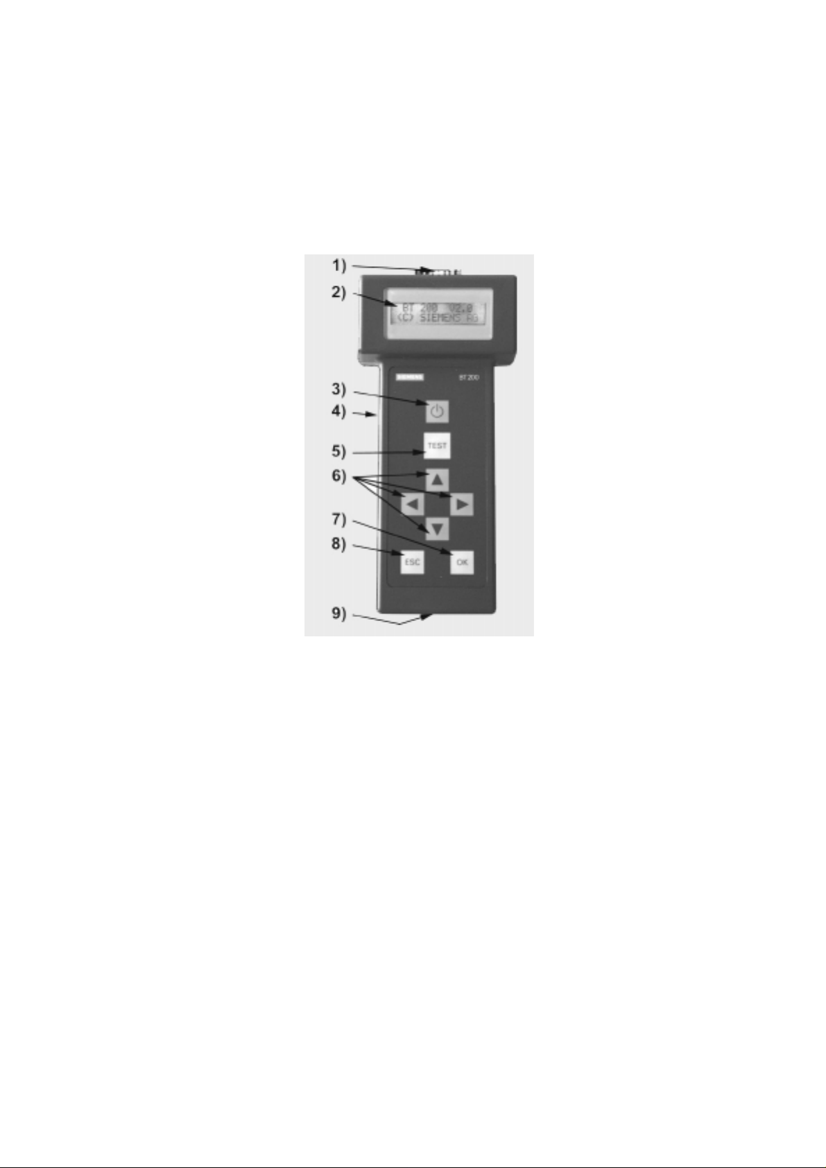
Operator control elements and display
Fig. 1 BT 200 operator control elements and display
1) PROFIBUS-DP connection (9-pin sub D)
2) LC display (2 x 16 characters )
3) ON/OFF button
4) Charging socket for plug connector/charging device
5) TEST key (start test)
6) CURSOR keys
7) OK key (various functions)
8) ESCAPE key (terminate)
9) Charging contacts for charging device
(S)J31069-D0075-U001-A2-6318 Page 3
Page 4

English 04/00 BT 200
2 Commissioning
Before initial commissioning , chec k your delivery, and charge the battery.
Scope of delivery
The delivery includes:
- 1 BT 200
- 1 battery
- 1 test plug connector (wiring test)
- 1 test cable, length: 2 m (station test)
- 1 user’s guide
Charging the battery
- Open the battery compartment (see
chapter on changing the battery), and
check to determine whether the battery is
installed. Install the battery if necessary.
- Charge battery of the BT 200 via char-
ging shell (approx. 4 hours).
U Attention!
The battery is always delivered uncharged.
The charging shell is not included and must
be ordered separately.
- Measuring cannot be performed during
the charging procedure.
(S)J31069-D0075-U001-A2-6318Page 4
Page 5
BT 200 04/00 English
3 Normal Mode
The BT 200 is turned on with the ON/OFF
button.
Keep the ON/OFF button pressed until you
see a reaction on the display.
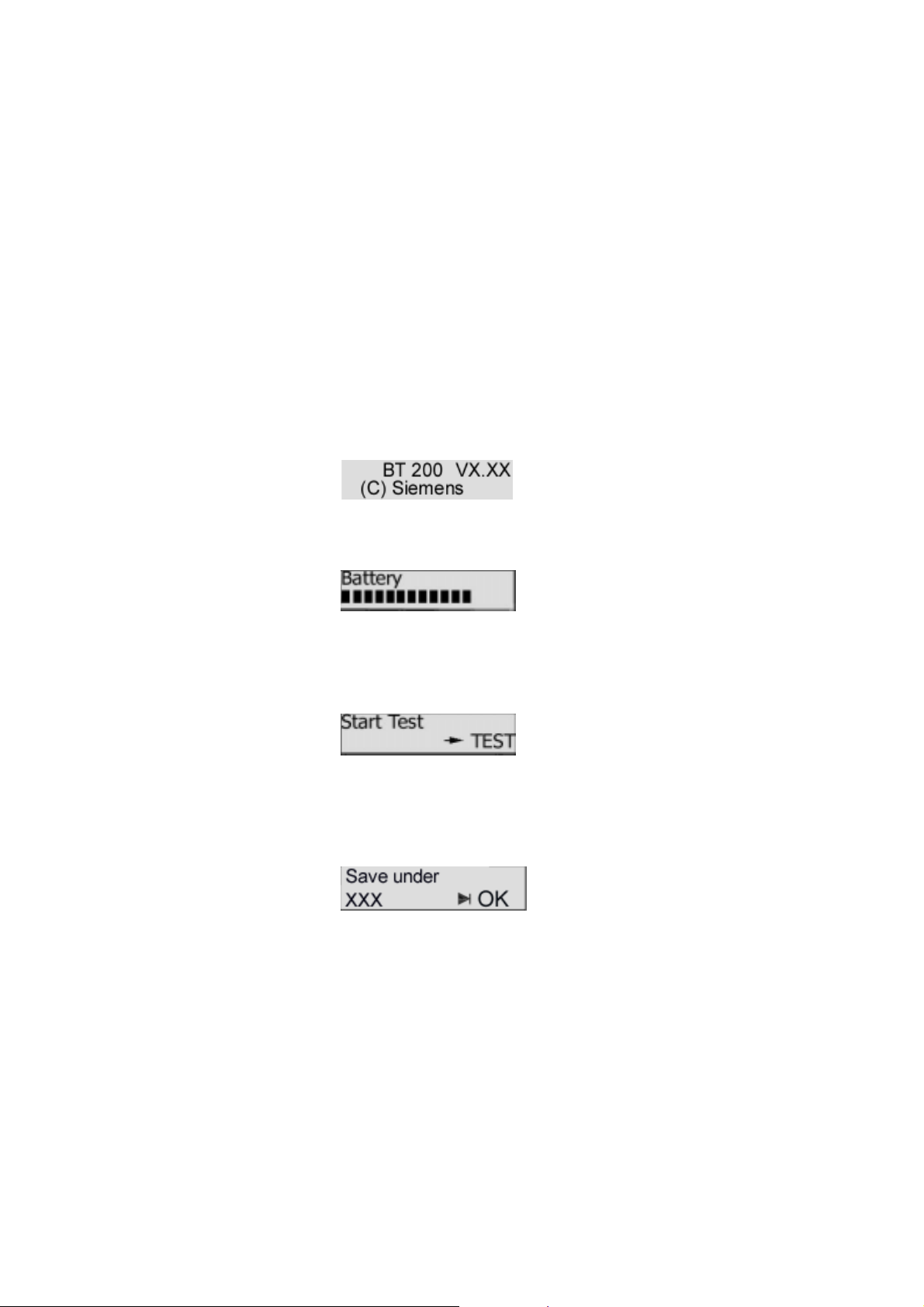
Standby display
The following display appears for approx. 2
seconds after the device is turned on.
Battery display
The battery capacity display is then shown for
approx. 2 seconds.
Operational display
After the battery display disappears, the BT
200 assumes normal mode and displays the
start screen for the wiring test.
Only the wiring test can be performed in normal mode.
When the BT 200 is in log mode (the cursor
looks different), an extra screen appears after
each test.
Energy saver mode
If no keys are pressed for approx. 3 minutes
and no measurements are being performed,
the BT 200 goes off automatically.
(S)J31069-D0075-U001-A2-6318 Page 5
Page 6
English 04/00 BT 200
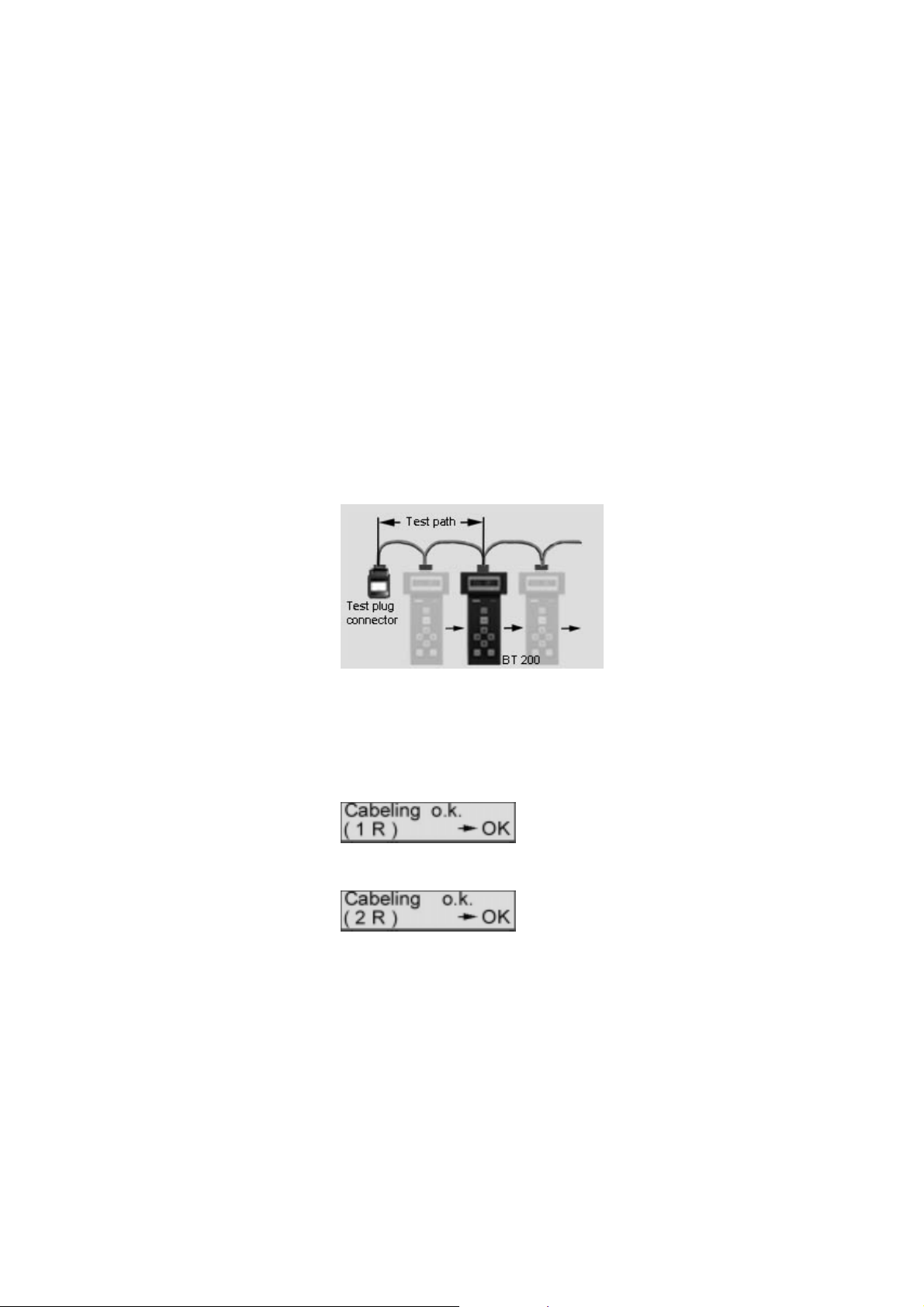
3.1 Wiring Test
Principle of measuring
The wiring test for a bus segment is performed between the BT 200 and the test plug
connector. During the installation phase, a
test can be performed from connector to connector. See figure 2. The test connector is
always installed on the one end of the bus
segment.
Short circuits can also be determined outside
the test path. The bus segment may only be
equipped with a terminating resistor at the
beginning and at the end.
Fig. 2 S t ep-by-step measuring principle
Performing the test
The test can be performed with or without
stations connected.
The test is started by pressing the TEST key.
One of the following two messages is displayed if the test was concluded successfully.
For one terminating resistor (as long as installation has not been completed, only one
terminal resistor is present)
After installation has been concluded, two resistors must be inserted.
The test is concluded by pressing the OK key,
and a new wiring test can be started.
The wiring test can also be concluded or terminated at any time by pressing the ESC key.
(S)J31069-D0075-U001-A2-6318Page 6
Page 7
BT 200 04/00 English
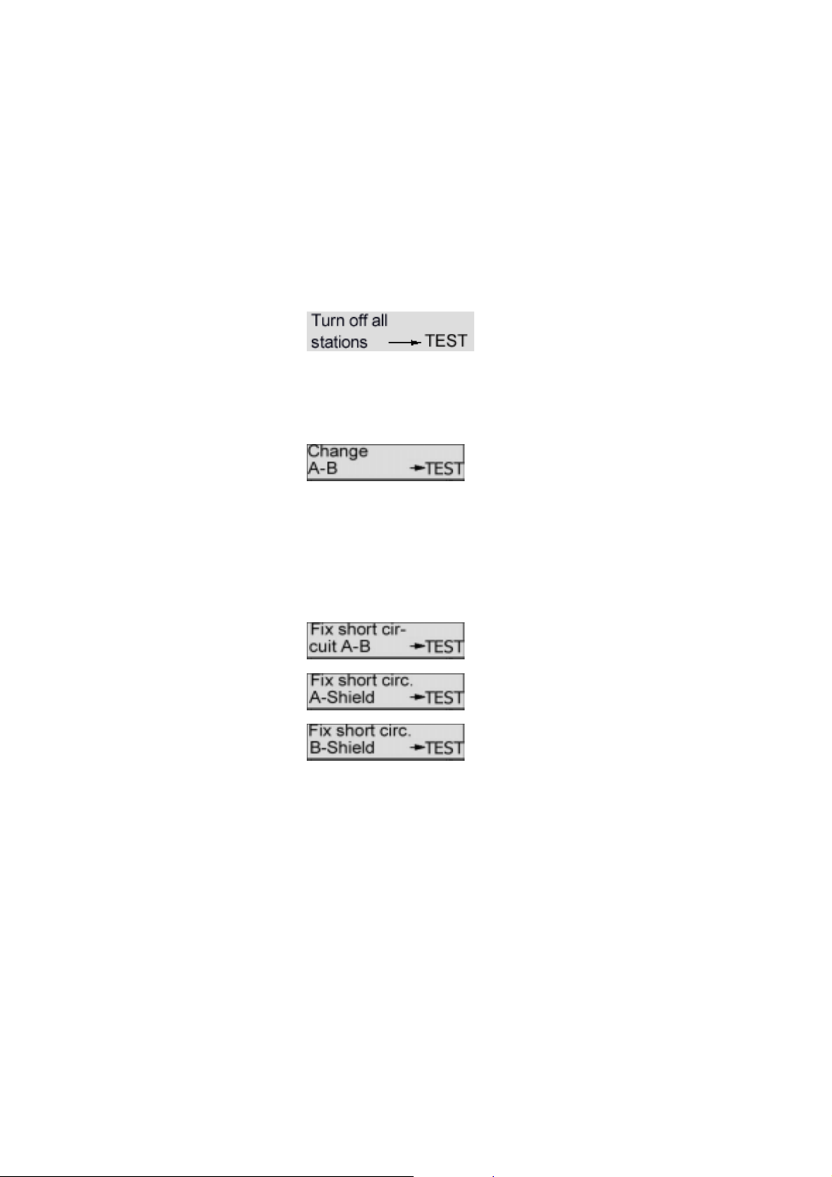
3.2 Error Messages of the Wiring Test
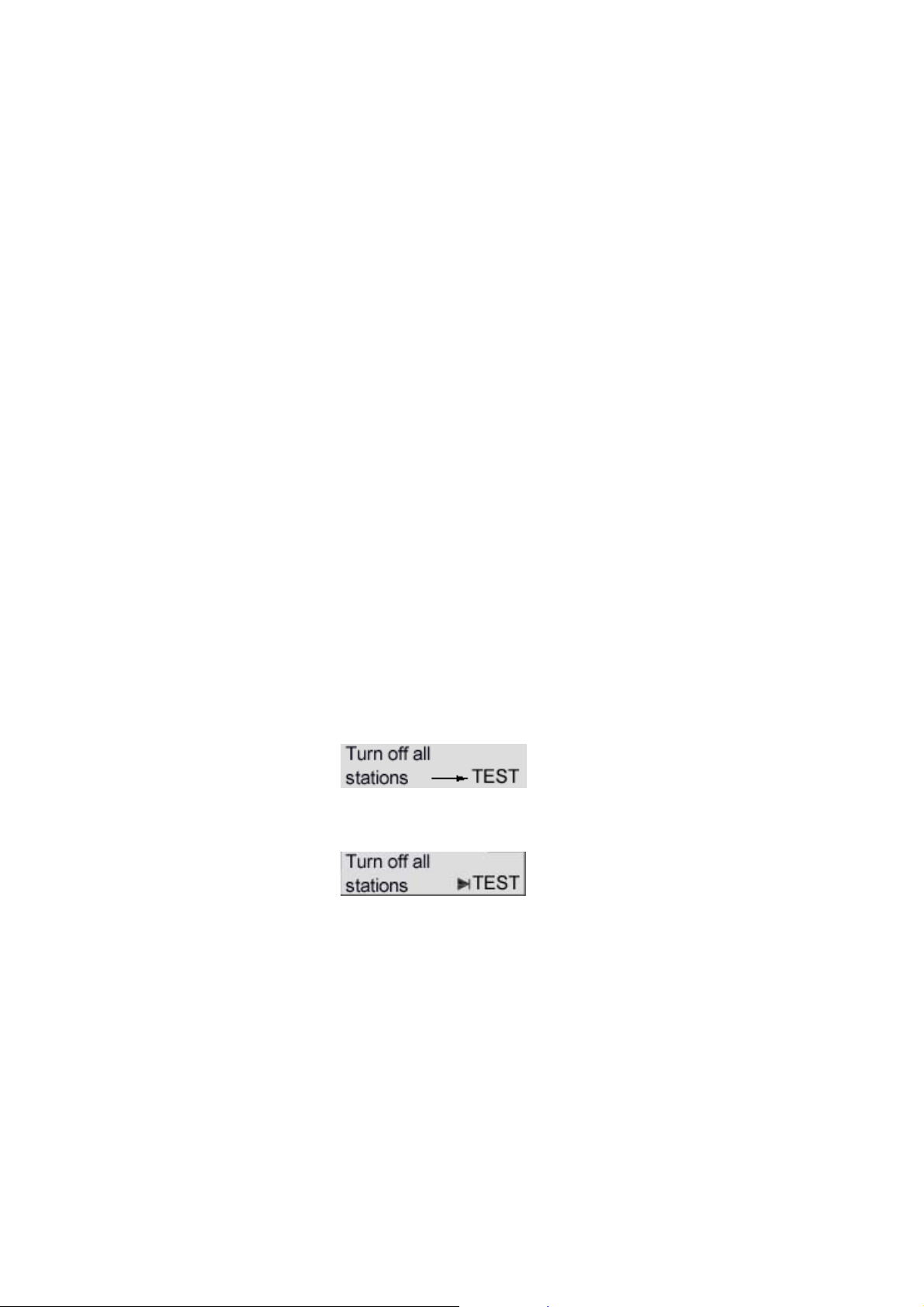
Station test
Check to determine whether the power supply
has been turned off for all stations and power
components.
Wire mix-up
Exchange the cores in the corresponding plug
connector.
U The wiring test must be performed each
time a new PROFIBUS plug connector is
connected. Otherwise an even number
of wire mix-ups will not be recognized.
Short circuit
Locate and correct the short circuit.
A frequent cause (e.g., of shield short circuits)
is the incorrect application of shield braiding in
the plug connectors.
(S)J31069-D0075-U001-A2-6318 Page 7
Page 8
English 04/00 BT 200
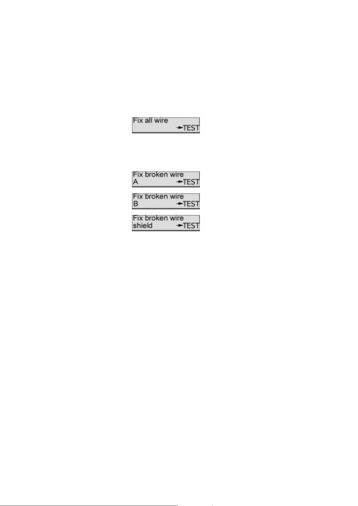
Line or shield break
Possible error causes:
• Interruption of several cores
• Interruption of cores and shield
• Test plug connector not connected
To obtain a correct measuring result for shield
break, the shield may not be connected with
ground.
With all four messages, first check the plug
connectors/connections in question. If these
are okay, replace the line.
(S)J31069-D0075-U001-A2-6318Page 8
Page 9
BT 200 04/00 English
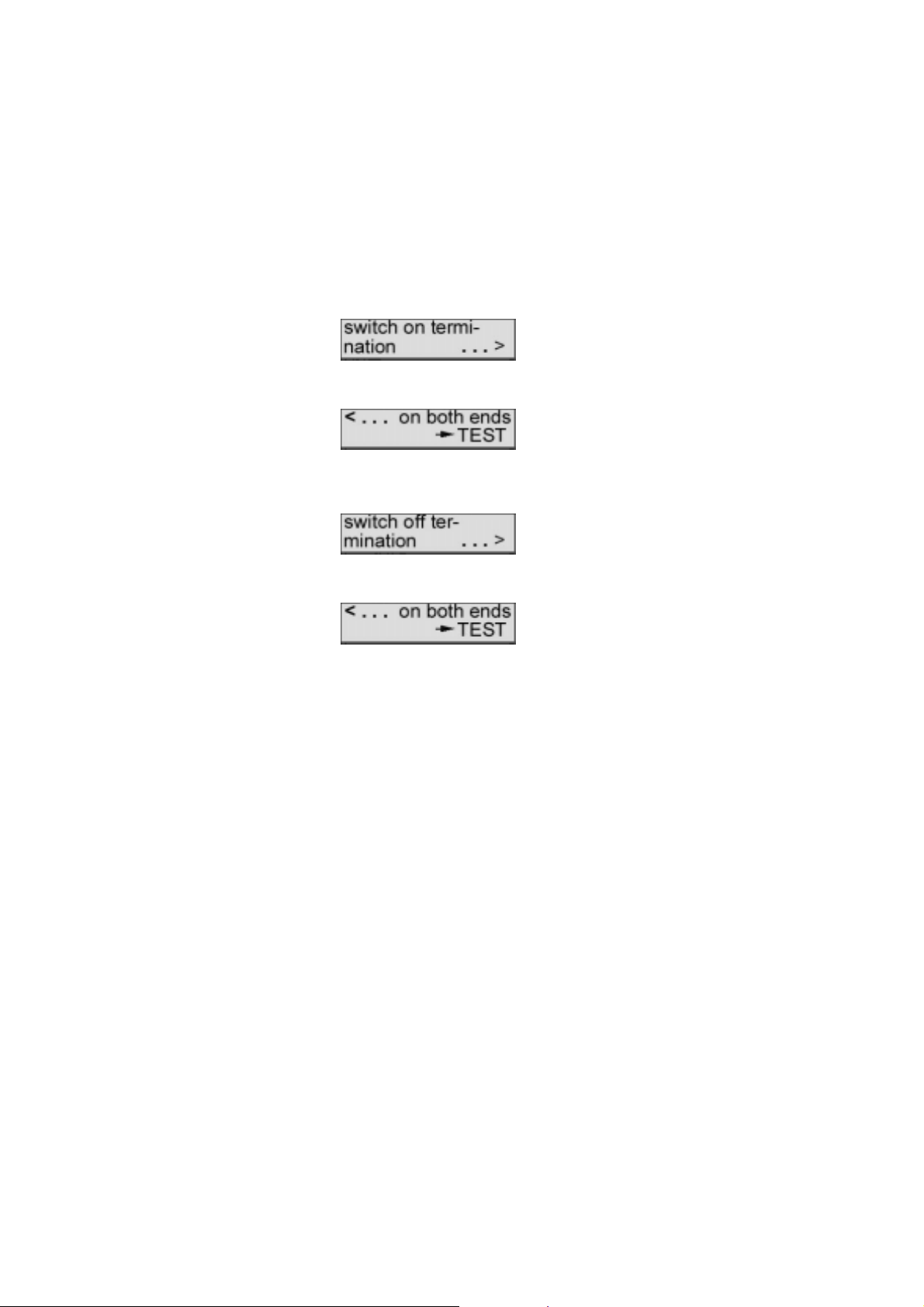
None or more than two terminating resistors
Page with the "→""←" keys.
Place a terminating resistor at the beginning
and end of the bus segment.
Page with the "→""←" keys.
Remove or deactivate all terminating resistors
except the two at the beginning and end of
the bus segment.
(S)J31069-D0075-U001-A2-6318 Page 9
Page 10
English 04/00 BT 200
4 Specialist Mode
You can switch from normal mode to specialist mode by pressing ESC and OK at the same time.
The following functions are available in specialist mode.
- Wiring test. See normal mode.
- Station test (RS 485 test)
- Branch test
- Distance measurement
- Reflection test
- Service menu
4.1 Operator Control
The BT 200 is menu-controlled via the input
keys of the sealed keyboard (figure 1).
Cursor
The current cursor position in the display is
shown as a flashing arrow and indicates the
function which is being performed.
If the BT200 is in log mode, the cursor position is shown with a modified arrow.
(S)J31069-D0075-U001-A2-6318Page 10
Page 11
BT 200 04/00 English
Menu items
Menu items are selected with the cursor and
activated with the OK key. The ESC key can
be used to terminate a running function or to
jump back to the higher-level menu item.
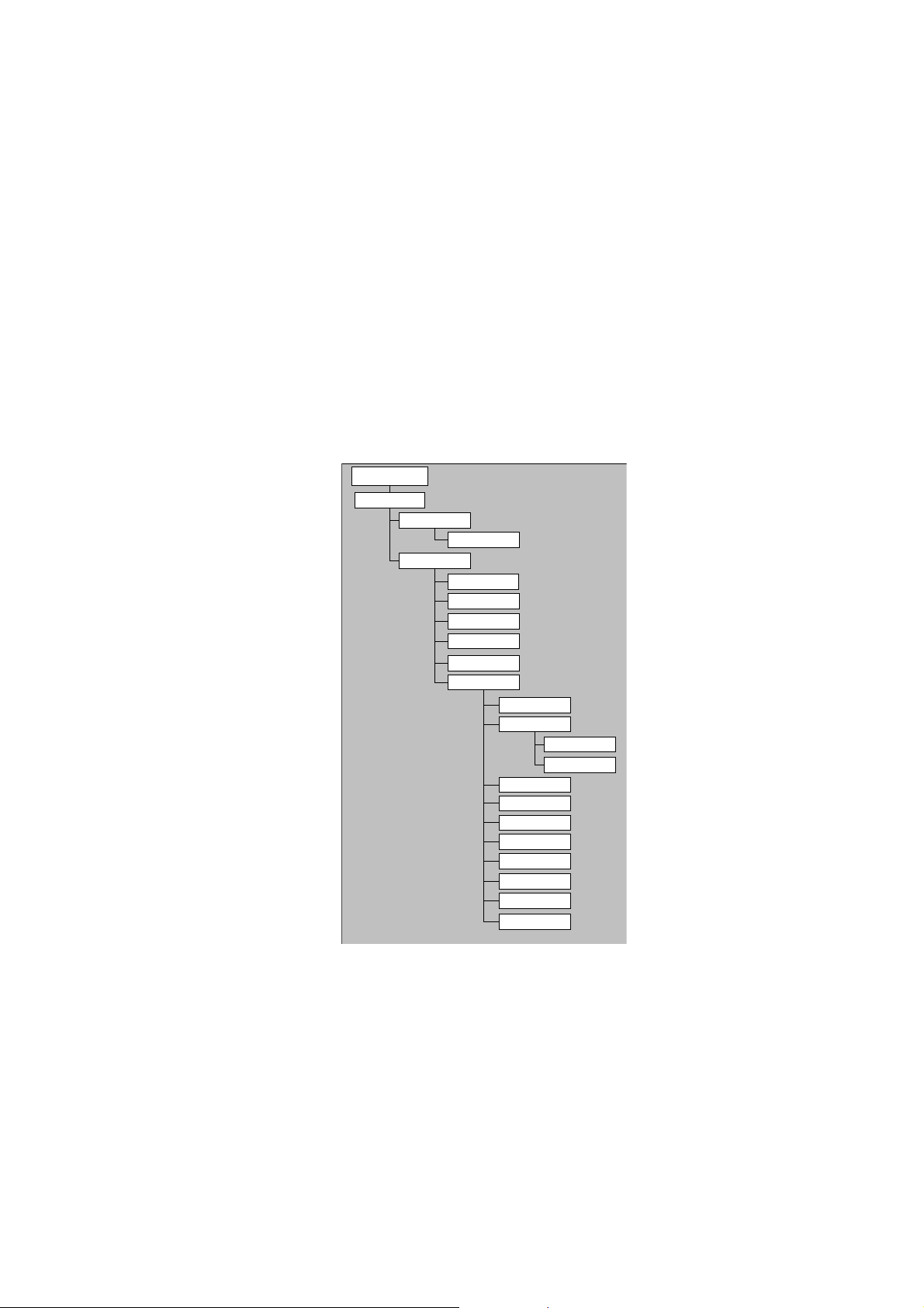
Menu structure
START
Battery test
N mode
s comde
(Normal mode)
Wiring
(Specalist mode)
Wiring
RS485
Branch
Distance
Reflection
SERVICE
(Test)
(Test)
(Test)
(Test)
(Measurement)
(Test)
(Settings)
Language
Settings
Baud rate
Resistance
Log mode
Communication
Battery
Contrast
Calibration
Deleting
FW version
Self test
Fig. 3 Menu st ructure
(S)J31069-D0075-U001-A2-6318 Page 11
Page 12
English 04/00 BT 200
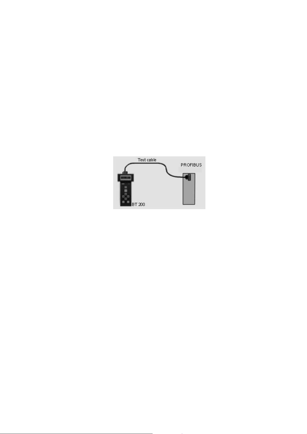
4.2 Station (RS 485) Test
This test is used to test the RS 485 interface
of a single slave or master.
Performing the test
Disconnect bus connector from the station.
Establish point-to-point connection between
station and BT 200. See figure 4.
U Only the included test cable may be used for
this connection.
station
Fig. 4 P oi n t -to-point connection
Turn on the station since the test must be
performed with an active station. The master
must be in "RUN" mode.
Start station test.
Set address of the station to be tested as
shown below.
Test results
Possible test results are listed below.
- RS 485 okay (slave okay)
- RS 485 defective. (No continuous signal
receipt; repeat test.)
- No response (nothing at all received)
- 5 V : (corresponding measured value)
- RTS signal (YES or NO)
(S)J31069-D0075-U001-A2-6318Page 12
Page 13
BT 200 04/00 English
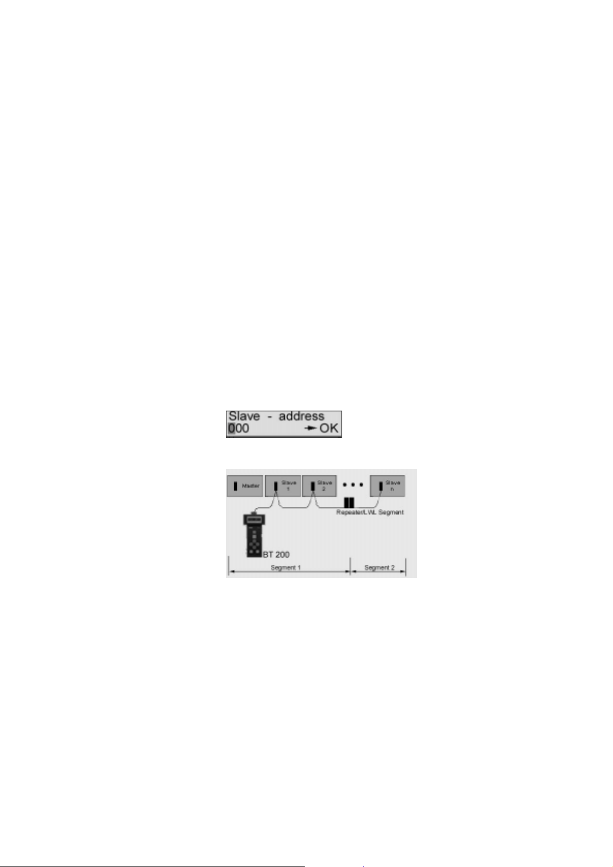
4.3 Branch Test
This can be used to check the availability of
all slaves on PROFIBUS or to address an in-
dividual slave.
The branch test can also be performed beyond repeaters/LWL.
Performing the test
Disconnect all masters from the bus (e.g., PG,
OP and CP). See figure 5.
Caution: The bus termination must remain
ensured.
Connect BT 200 to the bus.
Set the baud rate configured on the bus on
the BT 200.
Set the desired address for individual slave
test.
Set address to "000" for the total test.
Confirm with OK the address (slave or master) which was detected by the BT 200.
Fig. 5 Measuri ng pri nc i pl e of the branc h test
(S)J31069-D0075-U001-A2-6318 Page 13
Page 14
English 04/00 BT 200
Test results
During the total branch test, each available
slave is indicated in a list of available stations
(i.e., LIFE LIST).
- LIFE LIST
For an individual test
- No response (e.g., no station with this
bus address on the bus.)
- Faulty station (e.g., a slave number has
been assigned twice.)
(S)J31069-D0075-U001-A2-6318Page 14
Page 15

BT 200 04/00 English
4.4 Distance
Distance measurement can only detect lines
longer than 15 m. No distance measurement
can be performed when repeaters are used.
Performing the test
Turn off the power supply of all bus stations.
Connect test plug connector to one end of the
line and the BT 200 to the other end. (Turn
off resistor for BT 200.)
Start distance measurement.
After the start, the BT 200 requests three values which must be entered on the keyboard.
- Loop resistance (default = 110 Ω/km)
The default value can be changed via
menu item Service.
- Number of 12-Mbaud plug connec-
tors/devices with longitudinal inductivity
- Resistance value per connector/device
(default = 0.32 Ω)
After entry of the last value and confirmation
with OK, measurement is performed.
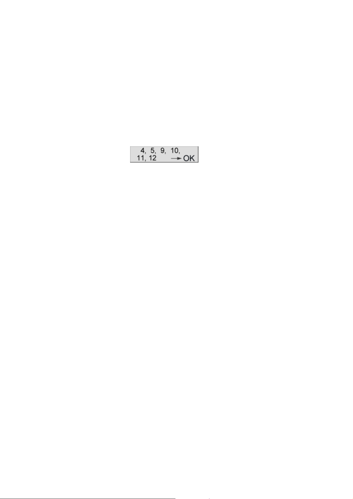
Measurement results
The following appears on the display.
The following error messages can occur during measurement.
- No resistor inserted.
- Display "0 m" (no plausible length deter-
mined)
- More than 1 resistor inserted.
Possible causes of errors:
- Distance < 15 m
- Stub lines, located on the measuring path
Correct the error, and repeat the measurement.
(S)J31069-D0075-U001-A2-6318 Page 15
Page 16
English 04/00 BT 200
4.5 Reflection Test
The reflection test can be used to determine a
faulty location (e.g., short circuit) or to confirm
the distance measurement (not via repeater).
Reflections can occur, for example, in the following situations:
- Stub lines exist.
- Too many terminating resistors have be-
en inserted, or none have been inserted.
- Change to a wrong type of cable occurs
within the measuring path.
Performing the test
Disconnect master from the bus, and make
sure that:
- the bus termination has power
- no bus communication occurs
- no test plug connector is connected.
Connect BT 200 to one end of the line.
Start reflection measurement.
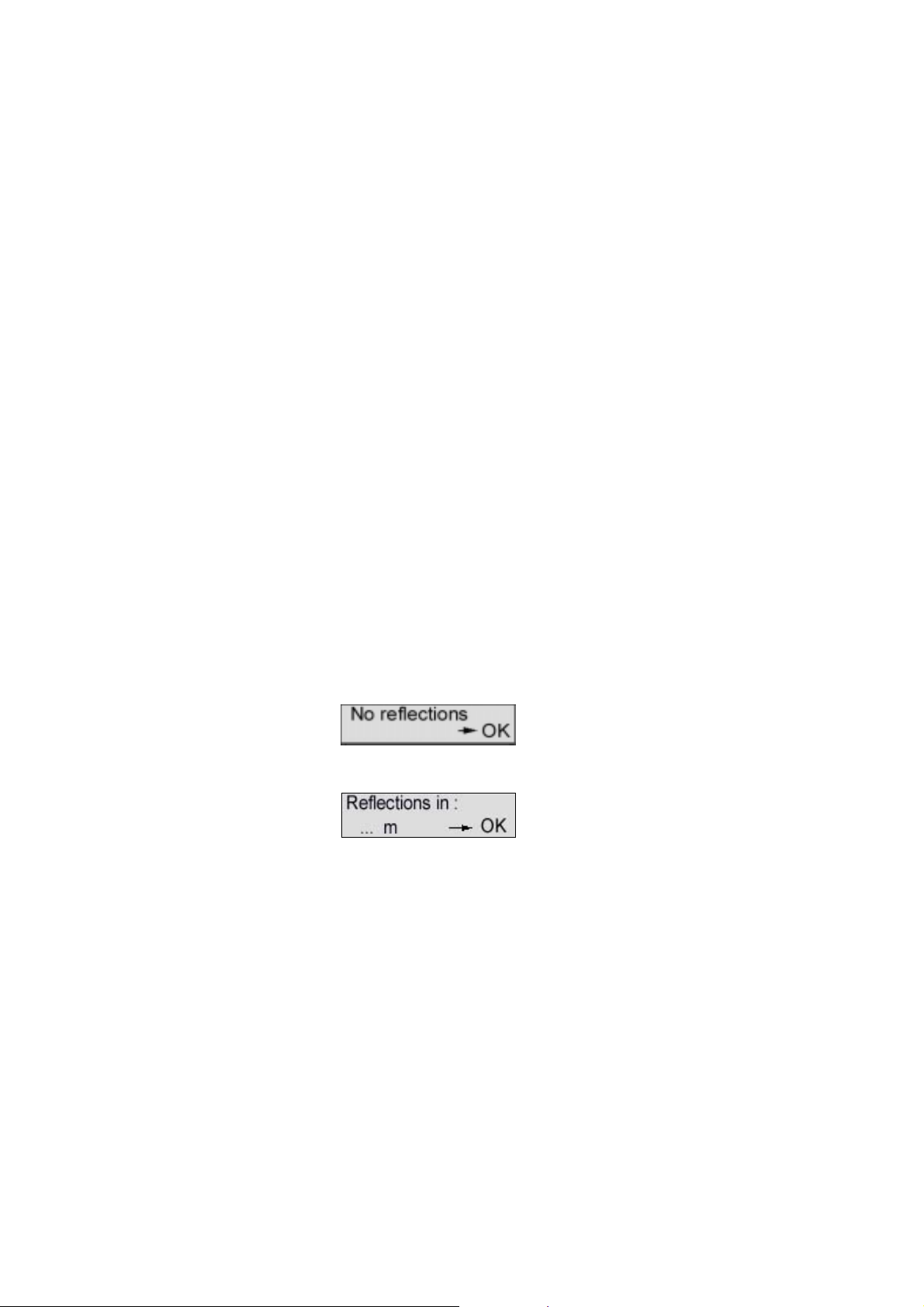
Test results
If no reflection (i.e., fault) is detected, the following message appears.
If a reflection is detected, the following message appears.
The number in the display specifies the distance in meters from the measuring point to
the faulty point.
If the distance of the reflection measurement
corresponds to a previous distance measurement, this distance measurement is confirmed. The wiring of the bus segment which
was measured is correct.
(S)J31069-D0075-U001-A2-6318Page 16
Page 17
BT 200 04/00 English
4.6 Service
Settings
The following settings can be changed in the
Service menu.
- Language (German/English/French/
- Italian/Spanish/Portuguese)
- Loop resistance (50 to 200 Ω/km)
- Baud rate (9600 baud to 12 Mbaud)
- Contrast (↑↓)
- Log mode (on/off)
Communication
Activate the interface for data transmission for
the log function.
Displays
The Service menu gives you the following information.
- Firmware version
- Battery capacity
Hardware test
This tests the internal hardware.
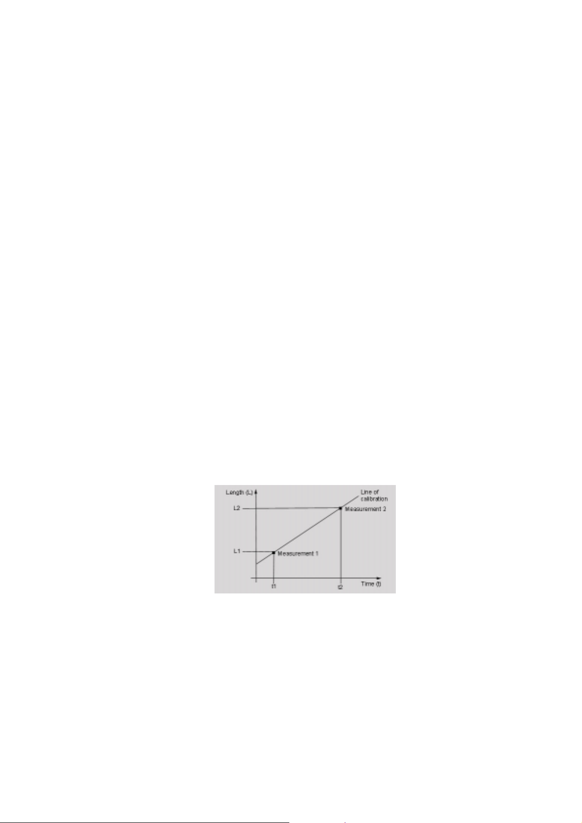
Calibration
Calibration is not necess ary when the standard type-A PROFIBUS cable is used.
The accuracy of distance and reflection measurement is achieved by calibration with 2 test
cables of different known lengths.
Fig. 6 P rinciple of calibration
(S)J31069-D0075-U001-A2-6318 Page 17
Page 18
English 04/00 BT 200
5 Log Mode
In log mode, performed tests are stored on
the BT 200. Later this inform ation can be
transferred over a serial interface to a PC with
log SW.
Log mode can be enabled and disabled in the
SERVICE menu.
Log mode remains set even when the BT 200
is turned off. This mode remains on until the
setting in the SERVICE menu is changed
again.
An identifier (X0 ..X999) is assigned to each
test to be stored on the BT 200.
The following table shows the maximum
number of tests which can be stored and their
identifiers.
Type of Test ID Letter Max. Number
Wiring test V 128
Station test T 128
Branch test S 10
Distance meas. E 10
Reflection test R 10
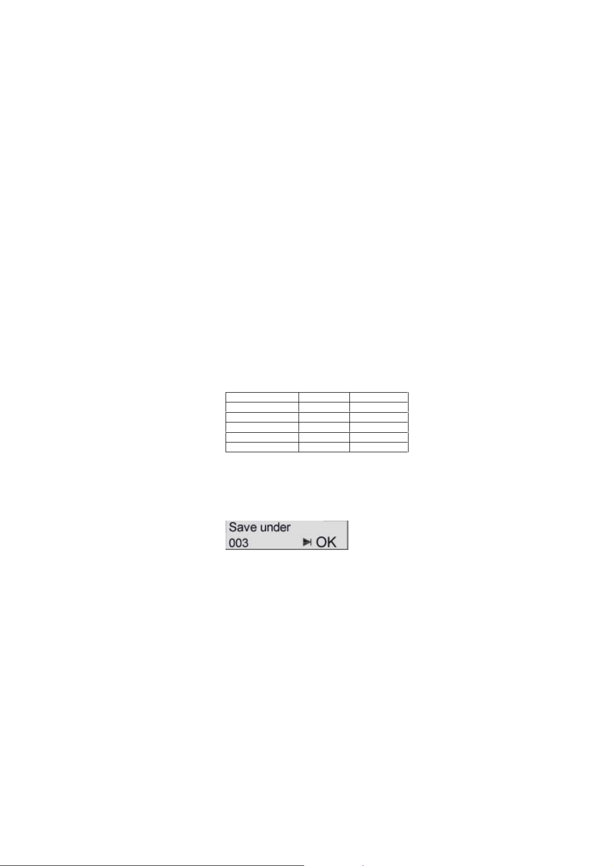
Storing the tests
After each test, the following prompt with the
next available identifier appears on the display.
The identifier can be changed with the cursor
or accepted with OK.
If you manually enter an identifier which has
already been assigned, it will be overwritten.
(S)J31069-D0075-U001-A2-6318Page 18
Page 19
BT 200 04/00 English
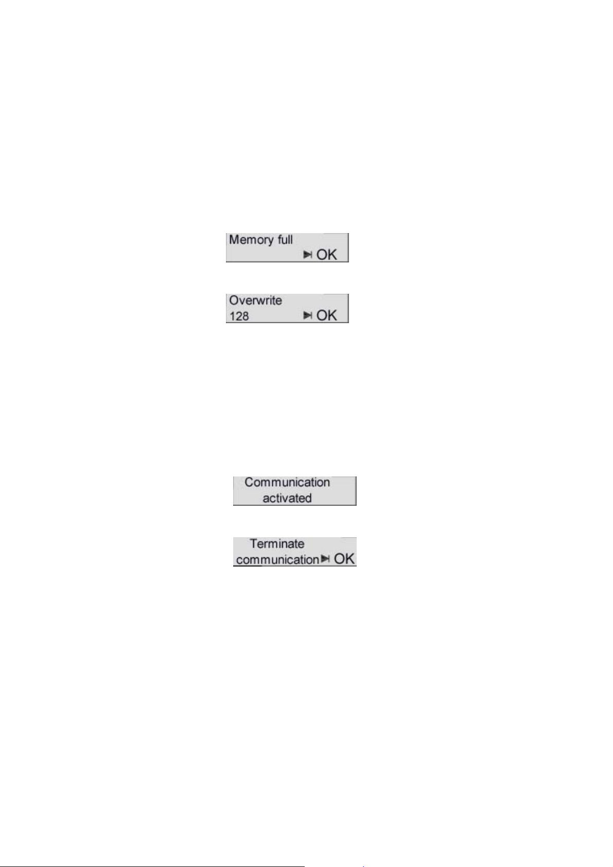
Memory full
This display appears when the maximum
number of tests to be stored is reached.
After you confirm with OK, the last selected
identifier appears which you can then
overwrite.
This identifier cannot be changed. The last
test result is overwritten.
Transferring tests to a PC
The test data are stored in non-volatile memory (i.e., they can be transferred to the PC
even after the BT 200 is turned off).
Before starting the transmission to the PC,
connect the included "log" cable to a COM
interface of the PC and to the 9-pin sub D
socket of the BT 200.
The transmission is activated with the
SERVICE menu and indicated on the display.
Communication can be terminated with the
ESC key. The following display appears.
OK terminates communication.
ESC terminates "termination" of communication.
Deleting the test data
The test data can be deleted with the
SERIVCE menu.
(S)J31069-D0075-U001-A2-6318 Page 19
Page 20
English 04/00 BT 200
6 Sample Applications
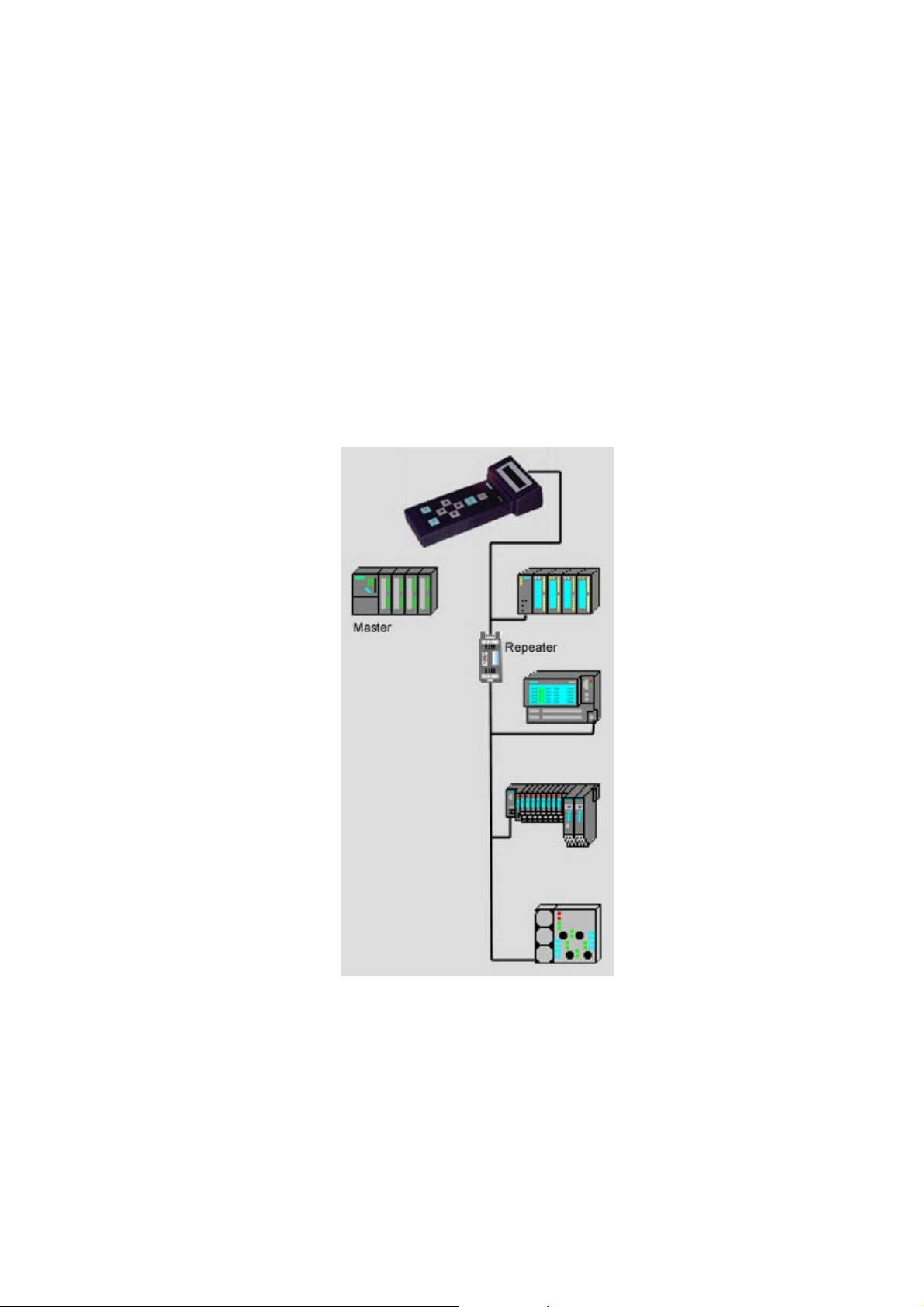
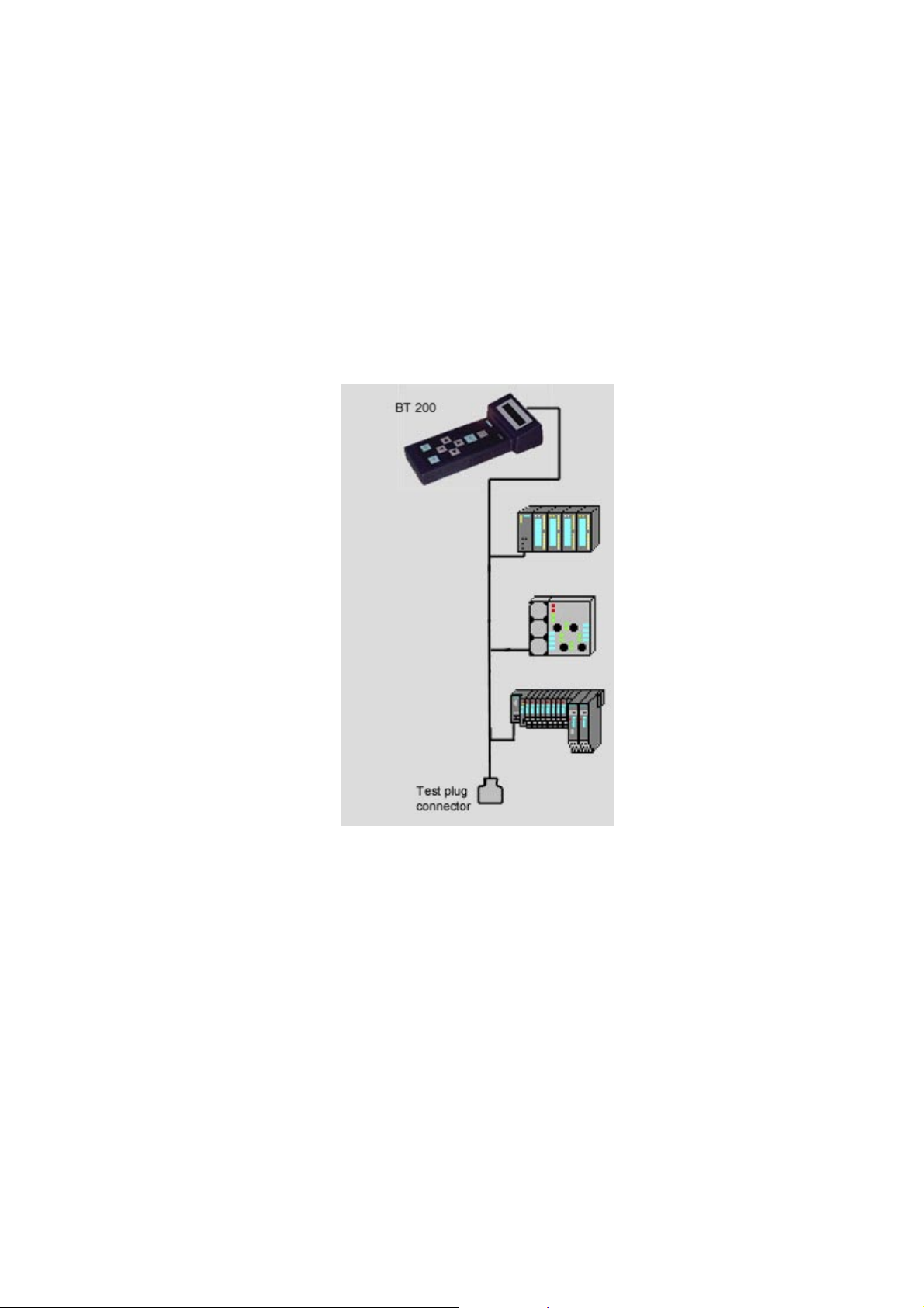
Testing the complete PROFIBUS-DP
• No master may be connected to the bus.
• The "life list" can also be generated with a re-
peater and optical paths.
• Parts of the system can be tested in advance
without the master for their bus functionality.
Fig. 7 S am pl e test 1
(S)J31069-D0075-U001-A2-6318Page 20
Page 21
BT 200 04/00 English
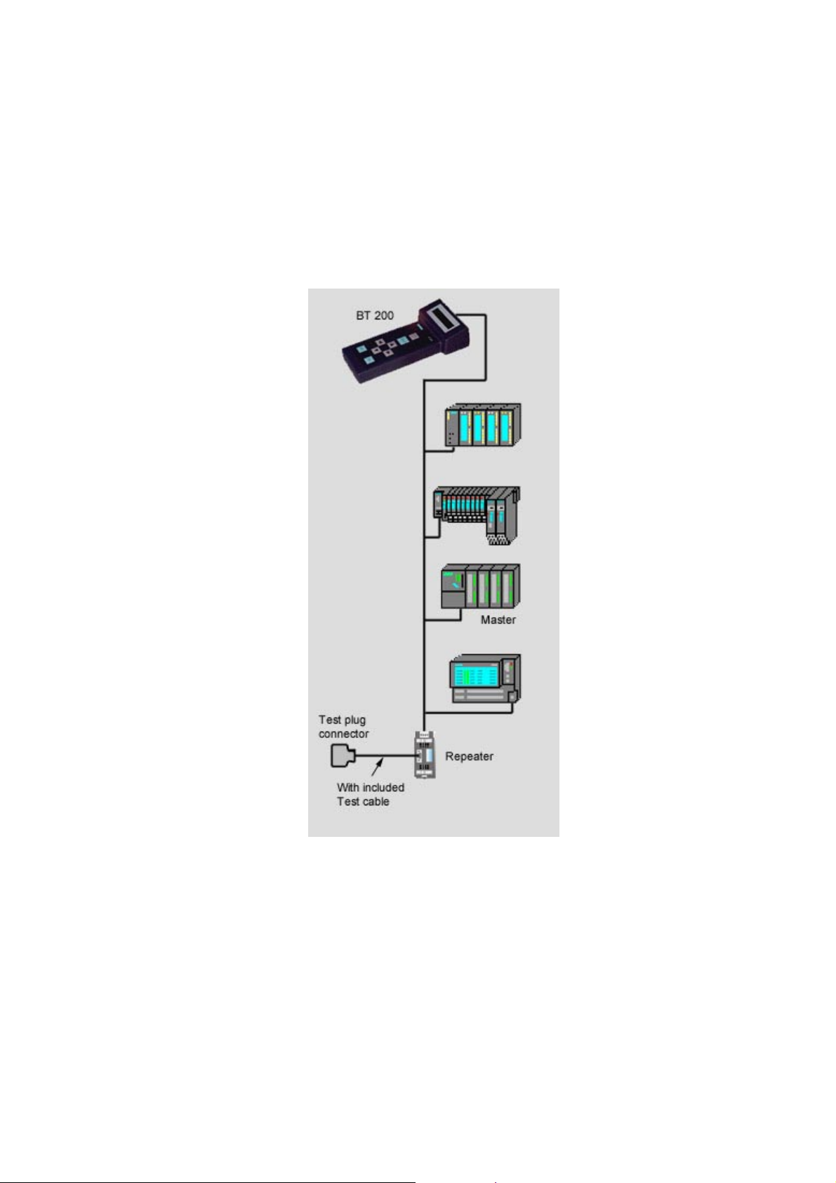
Wiring test for connected stations
• Stations no longer need to be removed from the
bus.
(Stations must be powered down!)
(Measurement not possible over repeater)
Fig. 8 S am pl e test 2
(S)J31069-D0075-U001-A2-6318 Page 21
Page 22
English 04/00 BT 200
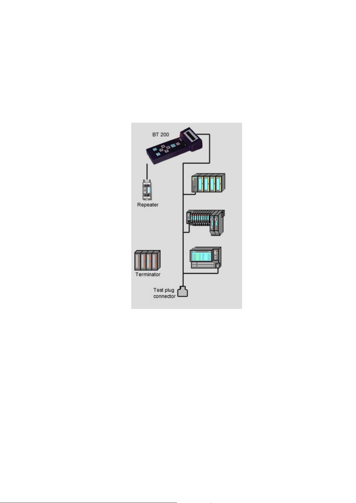
Wiring test of a segment via PG socket on the
repeater
Fig. 9 S am pl e test 3
(S)J31069-D0075-U001-A2-6318Page 22
Page 23
BT 200 04/00 English
Wiring test of a segment behind a repeater and
with terminator
Fig. 10 Sample test 4
(S)J31069-D0075-U001-A2-6318 Page 23
Page 24
English 04/00 BT 200
7 Maintenance and Trouble-
Shooting
7.1 Charging Status of the Battery
The charging status of the battery is indicated
for approximately 2 seconds during startup.
This display then disappears.
The charging status can also be indicated via
the service menu during operation.
If the battery goes dead during operation, the
charging status begins to flash.
Standard values
If you want to reset all values to their status
on delivery, keep both cursor keys pressed
for approx. three seconds after switch-on.
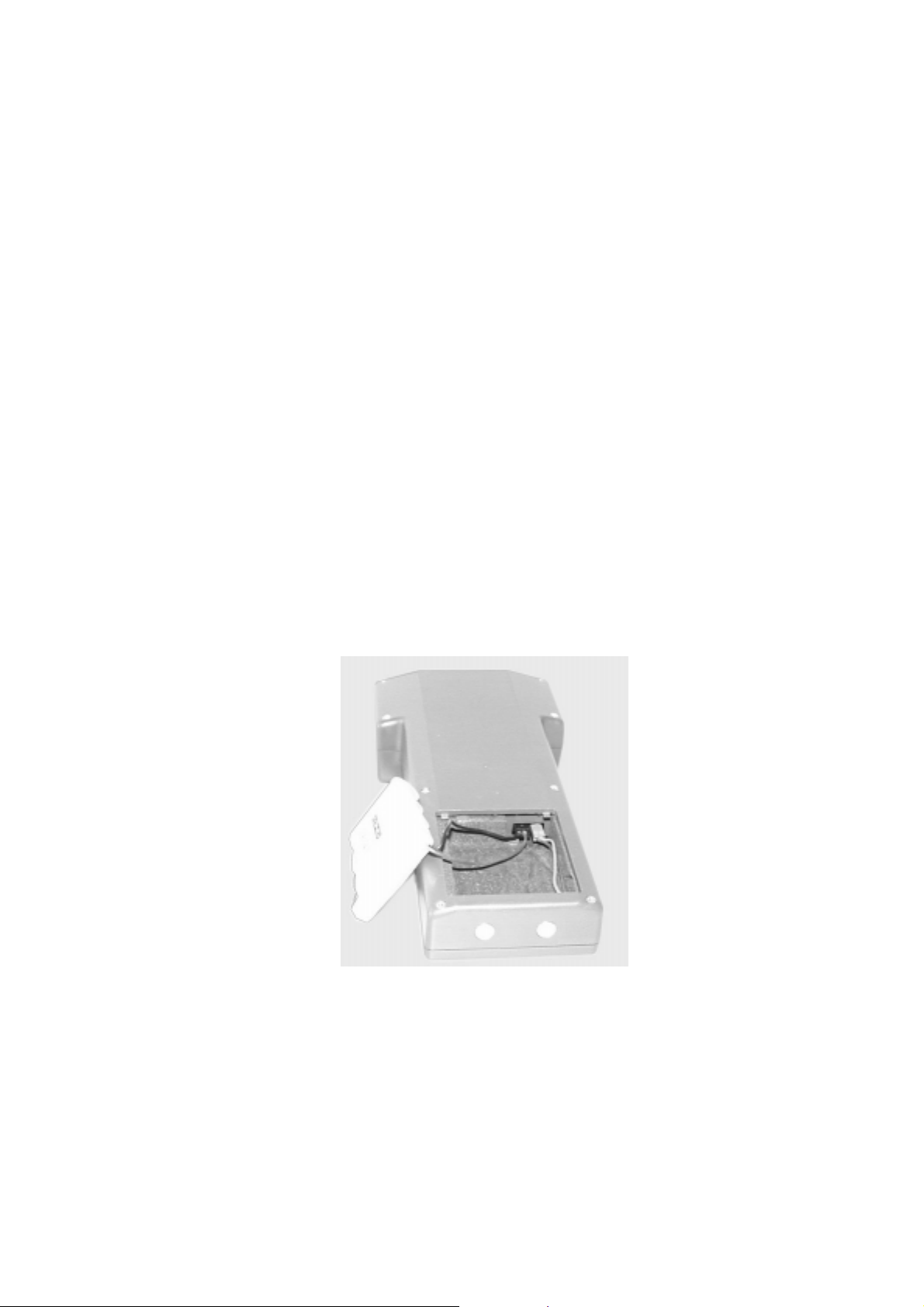
7.2 Changing the Battery
Fig. 11 Changing the battery
(S)J31069-D0075-U001-A2-6318Page 24
Page 25

BT 200 04/00 English
7.3 Self-Tests
The BT 200 performs self-tests automatically
and on request (hardware test).
- Internal RS 485 driver test
The test is performed each time the station and branch test is called.
- RAM test
A cyclic RAM test is performed.
- Flash EPROM test
A cyclic EPROM test is performed.
- RS 485 driver test
The individual tests (e.g., RAM test, flash
EPROM test and display key test) can also be
selected in specialist mode via service menu HW test.
If an error is detected during the self-test, you
must proceed as shown in the error correc-
tion table.
(S)J31069-D0075-U001-A2-6318 Page 25
Page 26

English 04/00 BT 200
7.4 Error Correction Table
Fault during startup
Display Fault Reason Effect Correc-
tion
None No dis-
play after
switch-on
If possible:
"internal
error"
message
Fault during operation
Display Fault Reason Effect Correc-
Battery
display
flashes
before.
None Device
Internal
driver
defect
After
switchon, "internal
error"
message
appears.
Device
goes off.
goes off.
Internal
driver is
defective.
Battery
dead
RAM/
EPROM
error
display/
keyboard
defective
Battery is
dead.
Time with
no user
activity
was
exceeded.
HW defect
Hardware
does not
start up.
No measuring
possible
No measuring
possible
None Press
No station/
branch
test
possible
Charge
battery
or install
new
battery.
Replace
BT 200.
tion
Charge
battery/
install
new
one.
ON/
OFF
button.
Replace
BT 200.
(S)J31069-D0075-U001-A2-6318Page 26
Page 27
BT 200 04/00 English
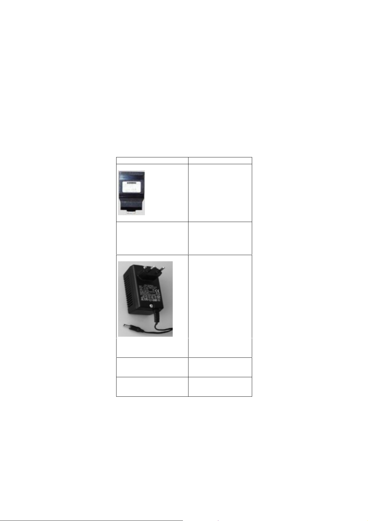
8 Accessories and Replacement
Parts
The following components can be ordered under
their MLFB number.
Designation/Picture MLFB Number
Test connector
6EP8106-0AC20
Log kit
for Win95/98/NT4
• CD-ROM in
Ger/Eng/French
• Cable
6ES7193-8MA00-0AA0
Plug-in charger w. power
pack for: 230 V AC
110 V AC
Battery with connection
cable
Test-cable station test
9-pin sub D on
9-pin sub D (1 to 1)
(S)J31069-D0075-U001-A2-6318 Page 27
6ES7193-8LA00-0AA0
6ES7193-8LB00-0AA0
6EP8106-HA01
6EP8106-OHC01
Page 28

English 04/00 BT 200
9 Technical Data
General
Dimensions 210 * 100 * 55 mm
Weight 400 g
Battery capacity
Life
Voltage supply NiCd, 4.8 V battery
Display LCD, 2 * 16 charac-
Baud rate 9600 Bd to 12 MBd
Protection class IP 20
Measuring accuracy Length measurement
Environmental Requirements
Operating temperature + 5°C to +45°C
Storage temperature -20°C to +60°C
Relative humidity Maximal 95% / 24°C
Air pressure
operation
storage
≥ 720 mAh
≥ 8 h
ters
(+/-3m)
Middle 75% / 17°C
(without
condensation)
795 to 1080 hPa
660 to 1080 hPa
EMC guidelines
CE labeling DIN EN 61326-1:
1998
EN 50 081-1
EN 50 082-2
Physical Requirements
Vibration during operation IEC 1131-2
Shock stress during operation IEC 1131-2
Free fall IEC 1131-2/68-2-32
Certifications
UL
CSA
Order number
(S)J31069-D0075-U001-A2-6318Page 28
6ES7 181-0AA010AA0
Page 29

BT 200 04/00 English
Abbreviations
Bd
Baud (1 Bd = 1 character (bit/second)
BT
CP
EMC
MBd
NiCd
NN
OP
PG
RTS
Physical bus test device
Communications processor
Electromagnetic compat ibi lity
6
1 MBd = 10
Nickel cadmium
Miles above sea level
Operator panel
Programmer
Request to send
baud
Info Info Info Info Info Info Info
This document can be downloaded free of charge
from the Internet under the following URL:
http://www.ad.siemens.de/simatic-cs
Continuous current information on SIMATIC products
is available on the Internet under:
http://www.ad.siemens.de/simatic
SIMATIC Customer Support can be reached under:
Tel. +49 (911) 895 7000
Fax. +49 (911) 895 7002
(S)J31069-D0075-U001-A2-6318 Page 29
Page 30

English 04/00 BT 200
(S)J31069-D0075-U001-A2-6318Page 30
Page 31

BT 200 04/00 Deutsch
BT 200
Busphysik-Testgerät
für PROFIBUS-DP
Inhaltsverzeichnis
1 BESCHREIBUNG ......................................... 2
2 INBETRIEBNAHME ...................................... 4
3 NORMALMODUS ......................................... 5
3.1 VERDRAHTUNGSTEST.............................................6
EHLERMELDUNGEN DES VERDRAHTUNGSTESTS ......7
3.2 F
4 SPEZIALISTENMODUS ............................. 10
4.1 BEDIENUNG.........................................................10
4.2 TEILNEHMER- (RS485) TEST...............................12
TRANGTEST ......................................................13
4.3 S
NTFERNUNG......................................................15
4.4 E
4.5 REFLEXIONS-TEST...............................................16
ERVICE.............................................................17
4.6 S
5 PROTOKOLLIERMODUS ........................... 18
6 ANWENDUNGSBEISPIELE ....................... 20
7 WARTUNG UND FEHLERBEHEBUNG ..... 24
7.1 LADEZUSTAND DES AKKUS...................................24
KKU-WECHSEL .................................................24
7.2 A
7.3 SELBST - TESTS..................................................25
EHLERBEHEBUNGSTABELLE................................26
7.4 F
8 ZUBEHÖR UND ERSATZTEILE ................ 27
9 TECHNISCHE DATEN ................................ 28
(S)J31069-D0075-U001-A2-6318 Page 1
Page 32

Deutsch 04/00 BT 200
1 Beschreibung
Zweck des BT 200
Das BT 200 bietet Diagnosemöglichkeiten für
PROFIBUS-DP-Systeme ohne zusätzliche
Meßhilfsmittel, wie PC oder Oszilloskop.
BT200 Version 2
Das BT 200 Version 2 bietet zusätzlich
• Protokollierfunktion
• 6-sprachige Bedienoberfläche
• Test der PROFIBUS-DP-Master Schnitt-
stelle
• Anzeige der Master-Adresse
• Verdrahtungstest mit angeschlossenen
Teilnehmern
• neues, kostengünstiges KompaktLadegerät
(S)J31069-D0075-U001-A2-6318Page 2
Page 33

BT 200 04/00 Deutsch
Bedienelemente und Anzeige
Bild 1 Bedienelemente u. Anzeige
1) PROFIBUS-Anschluß (9-polig, Sub-D)
2) LC - Display (2x16 Zeichen)
3) EIN / AUS-Taste
4) Ladebuchse für Stecker/Ladegerät
5) TEST-Taste (Test starten)
6) CURSOR-Tasten
7) OK-Taste (verschiedene Funk tionen)
8) ESCAPE-Taste (Abbruch)
9) Ladekontakte für Ladegerät
(S)J31069-D0075-U001-A2-6318 Page 3
Page 34

Deutsch 04/00 BT 200
2 Inbetriebnahme
Vor der ersten Inbetriebnahme ist der Lieferumfang zu kontrollieren und der Akku aufzuladen.
Lieferumfang
Zum Lieferumfang gehören:
- 1 BT 200
- 1 Akku
- 1 Prüfstecker (Verdrahtungstest)
- 1 Prüfkabel, Länge 2m (Teilnehmertest)
- 1 Bedienungsanleitung
Akku laden
- Akku-Fach öffnen (siehe Kap. Akku-
wechsel) und kontrollieren, ob der Akku
eingesetzt ist (ggf. eins etzen).
- Eingesetzten Akku des BT 200 über
Ladegerät aufladen (ca. 4 Stunden).
U Achtung!!
Der Akku wird immer in entladenem Zustand
ausgeliefert !
Das Ladegerät gehört nicht zum Lieferumfang
und muß separat bestellt werden.
- "Während des Ladevorgangs ist kein
Messbetrieb zulässig"
(S)J31069-D0075-U001-A2-6318Page 4
Page 35

BT 200 04/00 Deutsch
3 Normalmodus
Mit der ON/OFF-Taste wird das BT 200 eingeschaltet.
Die ON/OFF-Taste muß solange gedrückt
bleiben, bis am Display eine Reaktion erfolgt.
Bereitschaftsanzeige
Nach dem Einschalten erscheint für ca. 2
Sek. die Bereitschaftsanzeige.
Akku-Anzeige
Anschließend wird für ca. 2 Sek. die AkkuKapazitäts-Anzeige eingeblendet.
Betriebsanzeige
Nach Verlöschen der Akku-Anzeige wechselt
das BT 200 in den Normalmodus und zeigt
das Startfenster für den Verdrahtungstest an.
Im Normal-Modus kann nur der Verdrahtungstest durchgeführt werden.
Befindet sich das BT 200 im Protokolliermodus (erkennbar am verändertem Cursor), erscheint nach jedem Test die zusätzliche Abfrage
Stromspar-Modus
Wird ca. 3 Minuten lang keine Taste gedrückt
oder keine Messung durchgeführt, schaltet
das BT 200 automatisch ab.
(S)J31069-D0075-U001-A2-6318 Page 5
Page 36

Deutsch 04/00 BT 200
3.1 Verdrahtungstest
Meßprinzip
Der Verdrahtungstest für ein Bussegment erfolgt zwischen BT 200 und dem Prüfstecker.
Während der Installationsphase kann von
Stecker zu Stecker geprüft werden (Bild 2).
Der Prüfstecker ist dabei immer an dem einem Ende des Bussegmentes aufgesteckt.
Kurzschlüsse können auch außerhalb der
Teststrecke festgestellt werden. Das Bussegment darf nur am Anfang und am Ende
mit einem Abschlußwiderstand versehen sein.
Bild 2 Schrittweises Meßprinzip
Durchführung
Der Test kann mit oder ohne angeschlossene
Teilnehmer durchgeführt werden. Der Test
wird durch Drücken der TEST-Taste gestartet.
Bei erfolgreich abgeschlossenem Test erscheint eine der beiden Meldungen:
bei einem Abschlußwiderstand (solange die
Installation nicht abgeschlossen ist, ist nur ein
Abschlußwiderstand vorhanden)
nach Abschluß der Installation müssen zwei
Widerstände eingelegt sein.
Durch Drücken der OK-Taste wird der Test
beendet und ein neuer Verdrahtungstest kann
gestartet werden.
Der Verdrahtungstest kann auch durch Drükken der ESC-Taste beendet oder jederzeit
abgebrochen werden.
(S)J31069-D0075-U001-A2-6318Page 6
Page 37

BT 200 04/00 Deutsch
3.2 Fehlermeldungen des Verdrahtungstests
Teilnehmerprüfung
Bitte kontrollieren Sie, ob bei allen Teilnehmern und Netzkomponenten die Spannungsversorgung ausgeschaltet ist.
Leitungsdreher
Tauschen Sie die Adern im entsprechenden
Anschlußstecker.
U Der Verdrahtungstest muß jeweils nach
Anschluß eines neuen PROFIBUSsteckers durchgeführt werden. Andernfalls kann eine geradzahlige Anzahl von
Leitungsdrehern nicht erkannt werden!
Kurzschluß
Lokalisieren und beheben Sie den Kurz-
schluß.
Häufige Ursachen z.B bei Schirmschlüssen
sind unsachgemäß aufgelegte Schirmgeflechte in den Steckern.
(S)J31069-D0075-U001-A2-6318 Page 7
Page 38

Deutsch 04/00 BT 200
Leitungs- oder Schirmbruch
Mögliche Fehlerursachen:
• Unterbrechung mehrerer Adern
• Unterbrechung von Adern und Schirm
• Prüfstecker nicht gesteckt
Um ein korrektes Meßergebnis für den Bruch
Schirm zu erhalten, darf der Schirm nicht mit
der Erde verbunden sein.
Bei allen vier Meldungen überprüfen Sie
zuerst die in Frage kommenden Stecker/
Anschlüsse. Sind diese in Ordnung, tauschen
Sie die Leitung aus.
(S)J31069-D0075-U001-A2-6318Page 8
Page 39

BT 200 04/00 Deutsch
Keine- oder mehr als zwei Abschlußwiderstände
Mit den Tasten "→""←" blättern
Setzen Sie jeweils am Anfang und am Ende
des Bussegments einen Abschlußwiderstand
ein.
Mit den Tasten "→""←" blättern
Entfernen bzw. deaktivieren Sie alle Abschlußwiderstände bis auf die zwei am Anfang und Ende des Bussegments.
(S)J31069-D0075-U001-A2-6318 Page 9
Page 40

Deutsch 04/00 BT 200
4 Spezialistenmodus
Durch gleichzeitiges Drücken von ESC und
OK wird vom Normalmodus in den Speziali-
stenmodus umgeschaltet.
Im Spezialistenmodus stehen folg end e Funktionen zur Verfügung:
- Verdrahtungstest (siehe Normalmodus).
- Teilnehmertest (RS485-Test)
- Strangtest
- Entfernungsmessung
- Reflexionstest
- Service-Menü
4.1 Bedienung
Die Bedienung des BT 200 erfolgt menügesteuert über die Eingabetasten der Folientastatur (Bild 1).
Cursor
Die aktuelle Cursor-Position im Display wird
durch einen blinkenden Pfeil angezeigt und ist
die Funktion, die ausgeführt wird.
Befindet sich das BT 200 im Protokolliermodus, wird die Cursor-Position durch einen geänderten Pfeil angezeigt.
(S)J31069-D0075-U001-A2-6318Page 10
Page 41

BT 200 04/00 Deutsch
Menüpunkte
Menüpunkte werden mit dem Cursor angewählt und über die OK-Taste aktiviert. Mit der
ESC-Taste kann eine laufende Funktion abgebrochen werden oder ein Rücksprung in
den übergeordneten Menüpunkt erfolgen.
Menüstruktur
START
Akku-Test
N-Modus
S-Modus
(Normal-Modus)
Verdrahtung
(Spezialisten-Modus)
Verdrahtung
RS485
Strang
Entfernung
Reflexion
SERVICE
Einstellungen
Protokollmodus
Kommunikation
(Test)
(Test)
(Test)
(Test)
(Messung)
(Test)
(Einstellungen)
Sprache
Baudrate
Widerstand
Akku
Kontrast
Kalibrierung
Löschen
FW-Version
Selbst-Test
Bild 3 Menüstruktur
(S)J31069-D0075-U001-A2-6318 Page 11
Page 42

Deutsch 04/00 BT 200
4.2 Teilnehmer- (RS485) Test
Mit diesem Test wird die RS485-Schnittstelle
eines einzelnen Slave oder Master getestet:
Durchführung
Busstecker vom Teilnehmer abziehen.
Punkt-zu-Punkt-Verbindung zwischen Teilnehmer und dem BT 200 herstellen
(siehe Bild 4).
U Für diese Verbindung darf nur das mitgelie-
ferte Prüfkabel verwendet werden !
Bild 4 Punkt zu Punkt Verbindung
Teilnehmer einschalten (der Test muß bei aktivem Teilnehmer durchgeführt werden).
Teilnehmertest starten. Der Master muß auf
Betriebsart "RUN" stehen.
Testergebnisse
Folgende Testergebnisse sind möglich:
- RS 485 o.k. (Teilnehmer in Ordnung)
- RS 485 defekt (kein kontinuierlicher Si-
gnalempfang; Test wiederholen)
- Keine Antwort (überhaupt nichts
empfangen
- 5 V : (entsprechender Meßwert)
- RTS-Signal (JA oder NEIN)
(S)J31069-D0075-U001-A2-6318Page 12
Page 43

BT 200 04/00 Deutsch
4.3 Strangtest
Damit kann die Erreichbarkeit aller am
PROFIBUS befindlichen Slaves überprüft
oder ein einzelner Slave angesprochen werden.
Der Strangtest kann auch über Repeater/LWL
hinweg durchgeführt werden.
Durchführung
Alle Master vom Bus abziehen, z.B. PG, OP,
CP (siehe Bild 5).
Bitte beachten: Der Busabschluß muß gewährleistet bleiben.
BT 200 an den Bus anschließen.
Die am Bus projektierte Baudrate am BT 200
einstellen.
Für Slave-Einzeltest gewünschte Adresse
einstellen.
Für Gesamttest Adresse "000" einstellen.
Mit "OK " die vom BT 200 erkannte Adresse
(Slave oder Master) bestätigen.
Bild 5 Meßprinzip des Strangtests
(S)J31069-D0075-U001-A2-6318 Page 13
Page 44

Deutsch 04/00 BT 200
Testergebnisse
Beim Gesamtstrangtest wi rd jeder erreichbare
Slave in einer Liste der erreichbaren Teilnehmer (LIFE LIST) angezeigt.
- LIFE LIST
Bei einem Einzeltest
- Keine Antwort (z.B. kein Teilnehmer mit
der eingestellten Busadresse am Bus)
- Fehlerhafter Teilnehmer (z.B. doppelt
vergebene Slave-Nummer).
(S)J31069-D0075-U001-A2-6318Page 14
Page 45

BT 200 04/00 Deutsch
4.4 Entfernung
Mit der Entfernungsmessung können nur
Leitungsleitungen über 15m Länge ermittelt
werden. Die Entfernungsmessung ist nicht
über Repeater möglich.
Durchführung
Versorgungsspannung aller Bustei lne hmer
ausschalten.
Prüfstecker an ein Ende und BT 200 an das
andere Leitungsende stecken (Abschlußwiderstand bei BT 200 abschalten).
Entfernungsmessung starten.
Nach dem Start werden vom BT 200 drei
Werte abgefragt, die über die Tastatur einzugeben sind:
- Schleifenwiderstand (Standard = 110 Ω/km)
Der Standardwert kann über den Menüpunkt Service geändert werden.
- Anzahl der 12 MBaud-Stecker/Geräte mit
Längsinduktivität
- Widerstandswert pro Stecker/Gerät
(Standard = 0,32 Ω)
Nach Eingabe des letzten Wertes und Bestätigung mit OK wird die Messung durchgeführt.
Meßergebnis
Am Display erscheint folgende Anzeige
Während der Messung können folgende
Fehlermeldungen auftreten:
- Kein Widerstand eingelegt
- Anzeige “0 m“ (keine plausible Länge
ermittelt)
- Mehr als 1 Widerstand eingelegt
Mögliche Fehlerursachen:
- die Entfernung < 15m
- Stichleitungen innerhalb der Meßstrecke
Beseitigen Sie den Fehler und wiederholen
Sie die Messung.
(S)J31069-D0075-U001-A2-6318 Page 15
Page 46

Deutsch 04/00 BT 200
4.5 Reflexions-Test
Der Reflexionstest kann zur Ermittlung einer
Störstelle z.B. Kurzschluß, oder zur Bestätigung der Entfernungsmessung herangez oge n
werden (nicht über Repeater).
Reflexionen können z.B. auftreten, wenn:
- Stichleitungen vorhanden sind.
- zu viele Abschlußwiderstände oder keine
eingelegt sind.
- Innerhalb der Meßstrecke der Wechsel
auf einen ungeeigneten Kabeltyp erfolgt.
Durchführung
Master vom Bus nehmen und sicherstellen
dass:
- der Busabschluss mit Spannung versorgt
ist.
- daß kein Busverkehr stattfindet.
- kein Prüfstecker gesteckt ist
BT 200 an einem Leitungsende
anschließen.
Reflexionsmessung starten.
Testergebnis
Wird keine Reflexion (Störung) erkannt, erscheint die Meldung:
Wird eine Reflexion erkannt, erscheint die
Meldung:
Die angezeigte Zahl gibt die Entfernung in
Metern von der Meßstelle zur Störstelle an.
Stimmt die Entfernung der Reflexionsmessung mit einer vorangegangenen Entfernungsmessung überein, ist diese Entfernungsmessung bestätigt. Eine Störstelle in
der Verdrahtung des gemessenen Bussegmentes liegt nicht vor.
(S)J31069-D0075-U001-A2-6318Page 16
Page 47

BT 200 04/00 Deutsch
4.6 Service
Einstellungen
Im Service-Menü können folgende Einstellungen geändert werden:
- Sprache
(Deutsch/Englisch/Französisch/Italienisc
h/Spanisch/Portugiesisch)
- Schleifenwiderstand (50 - 200 Ω/km)
- Baudrate (9600 Baud - 12 MBaud)
- Kontrast (↑↓)
- Protokolliermodus (Ein/Aus)
Kommunikation
Aktivieren der Schnittstelle zur Datenübertragung für die Protokollierfunktion
Anzeigen
Im Service-Menü stehen Ihnen folgende Anzeigen zur Verfügung:
- Firmwa re - Version
- Akku - Kapazität
Hardware-Test
Damit kann die interne Hardware getestet
werden.
Kalibrierung
Bei Standard-PROFIBUS-Kabel Typ A ist keine Kalibrierung nötig.
Die Genauigkeit von Entfernungs- und Reflexionsmessung wird durch die Kalibrierung mit
2 verschieden langen Testleitungen mit bekannten Längen erreicht.
Bild 6 Prinzip der Kalibrierung
(S)J31069-D0075-U001-A2-6318 Page 17
Page 48

Deutsch 04/00 BT 200
5 Protokolliermodus
Im Protokolliermodus werden durchgeführte
Tests im BT 200 gespeichert und können
später per serieller Schnittstelle zu einem PC
mit Protokollier-SW übertragen werden.
Der Protokolliermodus kann über das
SERVICE-Menü ein- und ausgeschaltet werden.
Der Protokolliermodus bleibt auch nach Abschaltung des BT 200 eingestellt, bis die Einstellung im SERVICE-Menü wieder geändert
wird.
Jeder im BT 200 abzuspeichernde Test wird
mit einer Kennung versehen (0 ..999).
Die folgende Tabelle zeigt die maximal mögliche Anzahl von abzuspeichernden Tests und
die zugehörigen Kennungen:
Test-Art max.Anzahl
Verdrahtungstest 128
Teilnehmertest 128
Strangtest 10
Entfernungsmessung
Reflexionstest 10
10
Tests speichern
Nach jedem durchgeführten Test erscheint im
Display die Abfrage „Speichern unter“ mit der
nächsten freien Kennung.
Die Kennung kann per Cursor verändert oder
mit OK übernommen werden.
Wird bei manueller Eingabe eine Kennung
gewählt, die schon vergeben ist, so wird diese
überschrieben.
(S)J31069-D0075-U001-A2-6318Page 18
Page 49

BT 200 04/00 Deutsch
Speicher voll
Ist die maximale Anzahl der zu speichernden
Tests erreicht, so erscheint die Anzeige
Nach OK erscheint die zuletzt ausgewählte
Kennung und wird zum Überschreiben angeboten.
Diese Kennung kann nicht verändert werden,
das letzte Testergebnis wird überschrieben.
Tests an PC übertragen
Die Testdaten werden nicht flüchtig abgespeichert, d.h. sie können auch nach einem
Ausschalten des BT200 zum PC übertragen
werden.
Um die Übertragung zum PC zu starten,
muß das mitgelieferte Protokollier-Kabel an
eine COM-Schnittstelle des PC‘s und an die
9pol. Sub-D-Buchse des BT200 angeschlossen werden.
Die Übertragung wird über das SERVICEMenü aktiviert und im Display angezeigt.
Mit der ESC-Taste kann der Abbruch der
Kommunikation eingeleitet werden. Im Display erscheint die Abfrage:
Mit OK wird die Kommunikation abgebrochen.
Löschen der Testdaten
Die Testdaten können über das SERVICEMenü gelöscht werden.
(S)J31069-D0075-U001-A2-6318 Page 19
Page 50

Deutsch 04/00 BT 200
6 Anwendungsbeispiele
Testen des gesamten PROFIBUS-DP
• Es darf kein Master am Bus angeschlossen
sein.
• Die "Life-List" kann auch über Repeater und
optische Strecken hinweg erzeugt werden.
• Anlagenteile können vorab ohne Master auf
Funktionsfähigkeit des Busses geprüft werden.
Bild 7 Testbeispiel 1
(S)J31069-D0075-U001-A2-6318Page 20
Page 51

BT 200 04/00 Deutsch
Verdrahtungstest bei angeschlossenen Teilnehmern
• Teilnehmer brauchen nicht mehr vom Bus abge-
zogen werden
(Teilnehmer müssen spannung sfrei se in)
(Messung nicht über Repeater möglich)
Bild 8 Testbeispiel 2
(S)J31069-D0075-U001-A2-6318 Page 21
Page 52

Deutsch 04/00 BT 200
Verdrahtungstest eines Segments über
PG-Buchse am Repeater
Bild 9 Testbeispiel 3
(S)J31069-D0075-U001-A2-6318Page 22
Page 53

BT 200 04/00 Deutsch
Verdrahtungstest eines Segments hinter
einem Repeater und mit Terminator
Bild 10 Testbeispiel 4
(S)J31069-D0075-U001-A2-6318 Page 23
Page 54

Deutsch 04/00 BT 200
7 Wartung und Fehlerbehebung
7.1 Ladezustand des Akkus
Der Ladezustand des Akkus wird beim Anlauf
für ca. 2 Sekunden angezeigt. Danach wird
die Anzeige ausgeblendet.
Der Ladezustand kann während des Betriebs
zusätzlich über das Service-Menü angezeigt
werden.
Wird der Akku während der Betriebszeit leer,
wird der Ladezustand blinkend angezeigt.
Standardwerte
Wollen Sie alle Werte auf den Auslieferungszustand zurücksetzen, müssen Sie nach dem
Einschalten beide Cursor-Tasten für ca. drei
Sekunden gedrückt halten.
7.2 Akku-Wechsel
Bild 11 Akkuwechsel
(S)J31069-D0075-U001-A2-6318Page 24
Page 55

BT 200 04/00 Deutsch
7.3 Selbst - Tests
Das BT 200 führt automatisch und auf Anfor-
derung (Hardware Test) Selbsttests durch:
- Interner RS485 – Treiber – Test:
nach jedem Aufruf des Teilnehmer- und
Strang-Tests wird der Test durchgeführt.
- RAM-Test:
ein zyklischer RAM-Test wird durchgeführt
- Flash-EPROM-Test:
ein zyklischer EPROM-Test wird durchgeführt.
- RS485-Treiber-Test
Die einzelnen Tests, wie RAM-Test, FlashEPROM-Test und Display-Tasten-Test können auch aus dem Spezialisten-Modus über
das Service-Menü – HW-Test ausgewählt
werden.
Wird während des Selbsttests ein Fehler erkannt muß entsprechend der Fehlerbehe-
bungstabelle vorgegangen werden.
(S)J31069-D0075-U001-A2-6318 Page 25
Page 56

Deutsch 04/00 BT 200
7.4 Fehlerbehebungstabelle
Störung beim Anlauf
Anzeige Störung Grund Auswir-
kung
keine Keine
Anzeige
nach
dem Einschalten
Akku
entladen
kein
Hochlauf
der Hardware
Behebung
Akku
laden /
neuen
Akku
einlegen
wenn
möglich:
kommt
Meldung
"interner
Fehler"
Störung im Betrieb
Anzeige Störung Grund Auswir-
Akkuanzeige
blinkt
vorher
keine Gerät
interner
Treiber
defekt
nach Einschalten
erscheint
Meldung
"interner
Fehler"
Gerät
schaltet
sich aus
schaltet
sich aus
interner
Treiber
ist defekt
RAM/
EPROM
-Fehler
Display/
Tastatur
defekt
Akku ist
leer
Zeit
ohne
Bedienung
überschritten
HW
defekt
kein
Meßbetrieb
möglich
kung
kein
Meßbetrieb
möglich
keine ON/OFF
Kein
Teinehmer/
StrangTest
möglich
BT 200
austauschen
Behebung
Akku
laden /
neuen
einlegen
-Taste
drücken
BT 200
austauschen
(S)J31069-D0075-U001-A2-6318Page 26
Page 57

BT 200 04/00 Deutsch
8 Zubehör und Ersatzteile
Die folgenden Komponenten können unter Angabe
der entsprechenden MLFB-Nr. bestellt werden.
Bezeichnung/Bild MLFB-Nummer
Prüfstecker
6EP8106-0AC20
Protokollierkit
für Win 95/98/NT4
• CD-ROM in D/E/F
• Kabel
6ES7193-8MA00-0AA0
Steckerladegerät mit
Netzteil für:
230 V AC
110 V AC
Akku mit Anschlußkabel 6EP8106-0H A01
Prüfkabel für Teilnehmer
Test
9-polig-Sub-D auf
9-polig-Sub-D (1 zu 1)
(S)J31069-D0075-U001-A2-6318 Page 27
6ES7193-8LA00-0AA0
6ES7193-8LB00-0AA0
6EP8106-OHC01
Page 58

Deutsch 04/00 BT 200
9 Technische Daten
Allgemein
Abmessungen 210 * 100 * 55 mm
Gewicht 400 g
Akkukapazität
Betriebsdauer
Spannungsversorgung NiCd-Akku 4,8 V
Anzeige LCD, 2 * 16 Zeichen
Baudrate 9600 Bd … 12 MBd
Schutzart IP 20
Meßgenauigkeit Längenmessung +/-
Umgebungsbedingungen
Betriebstemperatur + 5°C bis +45°C
Lagertemperatur -20°C bis +60°C
Relative Luftfeuchtigkeit Maximal 95% / 24°C
Zul. Betriebshöhe (über NN) -1000m bis +2000m
EMV-Richtlinien
CE-Kennzeichnung DIN EN 61326-1:
≥ 720 mAh
≥ 8 h
3m
Mittel 75% / 17°C
(ohne Betauung)
1998
EN 50 081-1
EN 50 082-2
Mechanische Bedingungen
Schwingung im Betrieb IEC 1131-2
Schockbeanspruchung im
Betrieb
Freifall IEC 1131-2/68-2-32
Zulassungen
UL
CSA
Bestellnummer
(S)J31069-D0075-U001-A2-6318Page 28
IEC 1131-2
6ES7 181-0AA010AA0
Page 59

BT 200 04/00 Deutsch
Abkürzungen
Bd
Baud (1Bd = 1 Zeichen(Bit)/Sekunde)
BT
CP
EMV
MBd
NiCd
NN
OP
PG
RTS
Busphysik-Testgerät
Kommunikations-Prozessor
Elektromagnetische Verträglichkeit
6
1MBd = 10
Nickel-Cadmium
Normal Null (Meereshöhe)
Operator Panel
Programmiergerät
Request to send
Baud
Info Info Info Info Info Info Info
Diese Doku können Sie im Internet kostenfrei unter
der folgenden URL downloaden:
http://www.ad.siemens.de/simatic-cs
Ständig aktuelle Informationen zu den
SIMATIC-Produkten erhalten Sie im Internet unter:
http://www.ad.siemens.de/simatic
Den SIMATIC Customer Support erreichen Sie unter:
Tel. +49 (911) 895 7000
Fax. +49 (911) 895 7002
(S)J31069-D0075-U001-A2-6318 Page 29
Page 60

Deutsch 04/00 BT 200
(S)J31069-D0075-U001-A2-6318Page 30
Page 61

BT 200 04/00 Les français
BT 200
Testeur de physique de bus
pour DP PROFIBUS
Sommaire
1 DESCRIPTION .............................................. 2
2 MISE EN SERVICE ....................................... 4
3 MODE STANDARD ....................................... 5
3.1 TEST DU CÂBLAGE.................................................6
ESSAGES D’ERREURS DU TEST DU CÂBLAGE ..........7
3.2 M
4 MODE SPÉCIALISTE ................................. 10
4.1 COMMANDE.........................................................10
4.2 TEST DE LA STATION (RS485)..............................12
EST DE LA PHASE...............................................13
4.3 T
ISTANCE...........................................................15
4.4 D
4.5 TEST DE LA RÉFLEXION ........................................16
AINTENANCE.....................................................17
4.6 M
5 MODE D’ENREGISTREMENT .................... 18
6 EXEMPLES D’APPLICATION .................... 20
7 MAINTENANCE ET ELIMINATION DES
ERREURS ...................................................... 24
7.1 ETAT DE CHARGE DE L’ACCUMULATEUR.................24
EMPLACEMENT DE L’ACCUMULATEUR ..................24
7.2 R
UTO-CONTRÔLES ...............................................25
7.3 A
7.4 TABLEAU D’ÉLIMINATION DES ERREURS..................26
8 ACCESSOIRES ET PIÈCES DE
RECHANGE ................................................... 27
9 CARACTÉRISTIQUES TECHNIQUES ....... 28
(S)J31069-D0075-U001-A2-6318 Page 1
Page 62

Les français 04/00 BT 200
1 Description
Utilité du BT 200
Le BT 200 offre des possibilités de diagnostic
pour les systèmes DP PROFIBUS sans auxiliaires de mesure complémentaire s, tel s que
PC ou oscilloscope.
BT200 Version 2
Le BT 200 version 2 offre de plus :
• fonction d'enregistrement
• interface utilisateur en 6 langues
• test de l'interface maître DP PROFIBUS
• affichage de l'adresse maître
• test du câblage avec les stations raccor-
dées
• nouveau chargeur compact peu coûteux
Page 2
(S)J31069-D0075-U001-A2-6318
Page 63

BT 200 04/00 Les français
Éléments de commande et afficheur
Fig 1 Él éments de commande et afficheur
10) Connexion PROFIBUS (à 9 pôles, sub-
miniature D)
11) Afficheur LCD (2x16 caractères)
12) Touche MARCHE/ARRET
13) Douille de charge pour connecteur/chargeur
14) Touche de TEST (démarrage du test)
15) Touches CURSEUR
16) Touche OK (différentes fonctions)
17) Touche ESC (abandon)
18) Contacts de charge pour chargeur
(S)J31069-D0075-U001-A2-6318 Page 3
Page 64

Les français 04/00 BT 200
2 Mise en service
Avant la première mise en service, il convient
de contrôler l'étendue de la livraison et de
charger l'accumulateur.
Etendue de la livraison
La livraison englobe :
- 1 BT 200
- 1 accumulateur
- 1 connecteur d'essai (test du câblage)
- 1 câble d'essai, longueur 2 m (test de la
station)
- 1 notice d'utilisation
Charge de l’accumulateur
- Ouvrir le compartiment de l'accumula-
teur (voir le chapitre remplacement de
l'accumulateur) et s'assurer que l'accumulateur est en place (l'i nsérer le cas
échéant).
- Charger l'accumulateur inséré dans le
BT 200 par l'intermédiaire du chargeur
(pendant env. 4 heures).
U Attention !!
L'accumulateur est toujours fourni à l'état déchargé !
Le chargeur ne fait pas partie de la livraison
et doit être commandé séparément.
- "Aucune mesure n'est autorisée pendant
la charge."
Page 4
(S)J31069-D0075-U001-A2-6318
Page 65

BT 200 04/00 Les français
3 Mode standard
Le BT 200 est mis en marc he avec la touche
ON/OFF.
La touche ON/OFF doit être maintenue enfoncée jusqu'à l'apparition d'une réaction à
l'écran.
Affichage de l'état d'attente
L'affichage de l'état d'attente apparaît pendant
env. 2 s après la mise en marche.
Affichage de capacité de l'accumulateur
L'affichage de la capacité de l'accumulateur
apparaît ensuite pendant env. 2 s.
Affichage de fonctionnement
Quand la mention de l'accumulateur a disparu
de l'écran, le BT 200 passe en mode standard
et affiche la fenêtre de démarrage du test du
câblage.
Le mode standard ne permet d'effectuer que
le test du câblage.
Si le BT 200 se trouve en mode d'enregistrement (reconnaissable à la modification du
curseur), la demande supplémentair e suivante apparaît après chaque test :
Mode d'économie de courant
Le BT 200 passe automatiquement hors circuit si l’on n’a ppu ie sur aucu ne touc he pendant env. 3 minutes ou que l’on n’effectue aucune mesure.
(S)J31069-D0075-U001-A2-6318 Page 5
Page 66

Les français 04/00 BT 200
3.1 Test du câblage
Principe de mesure
Le test de câblage d'un segment du bus s'effectue entre le BT 200 et le connecteur d'essai. Pendant la phase d'installation, le
contrôle peut s'effectuer d'un connecteur à
l'autre (figure 2). Le connecteur d'essai est
alors toujours branché sur l'une des extrémités du segment du bus. Les courts-circuits
peuvent aussi être constatés en-dehor s de la
section de test. Le segment de bus ne doit
être muni d'une résistance terminale qu'au
début et à l'extrémité.
Fig 2 Pri ncipe de mesure progressive
Réalisation
Le test peut être effectué avec ou sans stations raccordées. Pour démarrer le test, appuyer sur la touche TEST.
Lorsque le test est terminé avec succès, l'un
des deux messages suivants apparaît :
avec une résistance terminale (tant que l'installation n'est pas terminée, il n'y a qu'une résistance terminale)
après la fin de l'installation, les deux résistances doivent être mises en place.
Une pression de la touche OK permet de
mettre fin au test et de démarrer un nouveau
test du câblage.
On peut également mettre fin au test du câblage ou l'interrompre à tout moment en appuyant sur la touche ESC.
Page 6
(S)J31069-D0075-U001-A2-6318
Page 67

BT 200 04/00 Les français
3.2 Messages d’erreur du test du câblage
Contrôle des stations
Veuillez contrôler si l'alimentation électrique
est coupée sur l'ensemble des stations et de
composants du réseau.
Interversion des câbles
Remplacez les brins dans le connect eur
correspondant..
U Le test du câblage doit être effectué
après le raccordement de chaque nouveau connecteur PROFIBUS. Il est sinon
impossible de détecter un nombre pair
d'interversions des câbles !
Court-circuit
Localisez et éliminez le court-circuit.
La pose incorrecte de tresses de blindage
dans les connecteurs constitue p. ex. une
cause fréquente de courts-circuits.
(S)J31069-D0075-U001-A2-6318 Page 7
Page 68

Les français 04/00 BT 200
Rupture de câble ou de blindage
Causes possibles de défaut :
• Coupure de plusieurs brins
• Coupure de brins et du blindage
• Connecteur d'essai non enfiché
Afin d'obtenir un résultat de mesure correct
pour la rupture du blindage, ce dernier ne doit
pas être relié à la terre.
Pour les quatre messages, commencez par
vérifier les connecteurs/connexions concernés. S'ils sont en bon état, remplacez le câble.
Page 8
(S)J31069-D0075-U001-A2-6318
Page 69

BT 200 04/00 Les français
Absence de résistance terminale ou plus de deux
résistances terminales
Faire défiler avec les touches "→""←"
Insérez une résistance terminale à chaque
extrémité du segment du bus (début et fin).
Faire défiler avec les touches "→""←"
Retirez ou désactivez toutes les résistances
terminales, sauf celles se trouvant à chaque
extrémité du segment du bus.
(S)J31069-D0075-U001-A2-6318 Page 9
Page 70

Les français 04/00 BT 200
4 Mode spécialiste
Une pression simultanée sur les touches ESC
et OK permet de passer du mode standard en
mode spécialiste.
Le mode spécialiste permet de disposer des
fonctions suivantes :
- test du câblage (voir mode standard).
- test des stations (test RS485)
- test de la phase
- mesure de la distance
- test de la réflexion
- menu service
4.1 Commande
La commande du BT 200 est guidée par menu, via les touches d'entrée du clavier à
membrane (figure 1).
Curseur
La position momentanée du curseur sur
l'écran est signalée par une flèche clignotante
et correspond à la fonction en cours d'exécution.
Lorsque le BT 200 se trouve en mode d'enregistrement, la position du curseur est signalée
par une flèche modifiée.
Page 10
(S)J31069-D0075-U001-A2-6318
Page 71

BT 200 04/00 Les français
Fonctions du menu
Les fonctions du menu sont sélectionnées au
moyen du curseur et activées via la touche
OK. La touche ESC permet d'interrompre une
fonction en cours ou de revenir dans la fonction ascendante.
Structure du menu
START
Akku-Test
N-Modus
S-Modus
(Normal-Modus)
Câblage
(Mode Spécialiste)
Câblage
RS485
rúseau
Distance
Réflexion
SERVICE
Enregistrement
Communikation
(Test)
(Test)
(Test)
(Test)
(Messurage)
(Test)
(Réglagles)
Langue
Réglagles
Vitesse
Ajouter une
Akku
Contrast
Kalibrierung
Effacent
FW-Version
Selbst-Test
Fig 3 Structure du menu
(S)J31069-D0075-U001-A2-6318 Page 11
Page 72

Les français 04/00 BT 200
4.2 Test des stations (RS485)
Ce test permet de contrôler l'interface RS485
d'un esclave ou d'un maître individuel :
Réalisation
Débrancher le connecteur de bus de la station.
Etablir une connexion point par point entre la
station et le BT 200 (voir figure 4).
U Pour ce raccordement, utiliser uniquement le
câble d'essai fourni !
Fig 4 Conne xion point par poi nt
Mettre la station sous tension (le test doit être
effectué lorsque la station est active).
Démarrer le test de la station. Le maître doit
se trouver sur le mode opératoire " RUN".
Résultats du test
Les résultats de test suivants sont possibles :
- RS 485 o.k. (station en ordre)
- RS 485 défectueux (absence de récep-
tion continue de signaux ; réitérer le test)
- Absence de réponse (absence totale de
réception
- 5 V : (valeur de mesure correspondante)
- Signal DPE (OUI ou NON)
Page 12
(S)J31069-D0075-U001-A2-6318
Page 73

BT 200 04/00 Les français
4.3 Test de la phase
Il permet de vérifier si tous les esclaves se
trouvant sur le PROFIBUS sont jo ignables, ou
de contrôler la réaction d'un esclave indivi-
duel.
Le test de la phase peut également être effectué via répéteur/câble à fibres optiques.
Réalisation
Débrancher tous les maîtres du bus, p. ex
PG, OP, CP (voir figure 5).
Attention : la terminaison du bus doit rester
garantie.
Raccorder le BT 200 au bus.
Régler sur le BT 200 la vitesse de transmission configurée sur le bus.
Pour le test individuel des esclaves, régler
l'adresse souhaitée.
Pour le test global, régler l'adresse "000".
Confirmer par "OK" l'adresse reconnue par le
BT 200 (esclave ou maître).
Fig 5 Pri ncipe de mesure du test de la phase
(S)J31069-D0075-U001-A2-6318 Page 13
Page 74

Les français 04/00 BT 200
Résultats du test
Lors du test global de la phase, chaque es-
clave pouvant être joint est affiché dans une
liste des stations accessibles ("LIFE LIST").
- "LIFE LIST"
Lors d'un test individuel
- Absence de réponse (p. ex. pas de sta-
tion avec l'adresse de bus réglée sur le
bus)
- Station erronée (p. ex. numéro d'esclave
attribué en double).
Page 14
(S)J31069-D0075-U001-A2-6318
Page 75

BT 200 04/00 Les français
4.4 Distance
La mesure de la distance ne s'applique qu'à
des câbles d'une longueur supérieure à 15 m.
La mesure de la distance n'est pas possible
par l'intermédiaire d'un répéteur.
Réalisation
Couper la tension d’alimentation de toutes les
stations du bus.
Brancher le connecteur d'essai à une extrémité et le BT 200 à l'autre extrémité du câble
(couper la résistance terminale avec le BT
200).
Démarrer la mesure de la distance .
Après le démarrage, trois valeurs devant être
entrées par le clavier sont demandées par le
BT 200 :
- résistance de boucle (standard = 110 Ω/km).
La valeur standard peut être modif iée par la
fonction service.
- Nombre de connecteurs/appareils
12 Mbauds avec inductance série
- Valeur de la résistance par
connecteur/appareil
(standard = 0,32 Ω)
La mesure est effectuée après entrée de la
dernière valeur et confirmation avec OK.
Résultat de la mesure
L'affichage suivant apparaît à l'écran :
Les messages d'erreur suivants peuvent se
présenter pendant la mesure :
- Aucune résistance insérée
- Affichage “0 m“ (aucune longueur plausi-
ble déterminée)
- Plus d'une résistance insérée
Causes possibles d'erreurs :
- distance < 15 m
- lignes de branchement à l'intérieur du
segment de mesure
Eliminez l'erreur et renouvelez la mesure.
(S)J31069-D0075-U001-A2-6318 Page 15
Page 76

Les français 04/00 BT 200
4.5 Test de la réflexion
Le test de la réflexion peut être utilisé pour
rechercher une imperfection, p. ex. courtcircuit, ou pour confirmer la mesure de la
distance (pas via répéteur).
Les réflexions peuvent p. ex. survenir dans
les cas suivants :
- présence de lignes de branchement.
- Un trop grand nombre de résistances
terminales sont insérées, ou aucune.
- Le changement s'effectue sur un type de
câble inadéquat à l'intérieur du segment
de mesure.
Réalisation
Sortir le maître du bus et s'assurer des points
suivants :
- la terminaison de bus est alimentée en
tension ;
- aucune circulation ne s'effectue sur le
bus ;
- Aucun connecteur de bus n'est enfich é.
Raccorder le BT 200 à une extrémité du câble.
Démarrer la mesure de la réflexion.
Résultat du test
Si aucune réflexion (perturbation) n'est détectée, le message suivant apparaît :
Si une réflexion est détectée, le message suivant apparaît :
Le nombre affiché donne la distance en mètres du point de mesure au point de perturbation. Si la distance obtenue lors de la mesure
de la réflexion correspond à celle d'une mesure préalable, cette mesure de la distance
est confirmée. Il n'y a pas de perturbation
dans le câblage du segment de bus mesuré.
Page 16
(S)J31069-D0075-U001-A2-6318
Page 77

BT 200 04/00 Les français
4.6 Service
Réglages
Les réglages suivants peuvent être modifiés
sous le menu service :
- Langue
(allemand/anglais/français/italien/espagnol/portugais)
- Résistance de boucle (50 - 200 Ω/km)
- Vitesse de transmission (9600 bauds -
12 Mbauds)
- Contraste (↑↓)
- Mode d'enregistrement (activé/coupé)
Communication
Activation de l'interface de transmission des
données pour la fonction d'enregistrement
Affichage
Vous disposez des affichages suivants sous
le menu service :
- version de firmware
- capacité de l'accumulateur
Test du matériel
Il permet de contrôler le matériel interne.
Calibrage
Avec le câble PROFIBUS standard de type A,
tout calibrage est superflu.
La précision de la mesure de la distance et de
la réflexion est atteinte par le calibrage dans
des longueur connues avec 2 câbles-test de
longueur différentes.
Fig 6 Pri nc i pe du calibrage
(S)J31069-D0075-U001-A2-6318 Page 17
Page 78

Les français 04/00 BT 200
5 Mode d’enregistrement
Sous le mode d'enregistrement, les tests effectués sont mémorisés dans le BT 200 et
peuvent être ultérieurement transmis par interface série vers un PC comportant un logiciel d'enregistrement.
Le mode d'enregistrement peut être activé et
coupé via le menu SERVICE.
Le mode d'enregistrement reste également
réglé après la coupure du BT 200, jusqu'à la
modification du réglage sous le menu
SERVICE.
Chaque test devant être mémorisé dans le
BT 200 est doté d'un code (0 ..999).
Le tableau ci-après montre le nombre maximum possible de tests devant être mémorisés
et les codes correspondants :
Type de test Nombre max.
Test du câblage 128
Test de la station 128
Test de la phase 10
Mesure distance 10
Test de réflexion 10
Mémorisation des tests
Après la réalisation de chaque test, l'instruction "mémoriser sous" s'affiche à l'écran avec
le code suivant disponible.
Le code peut être modifié par curseur ou accepté par une pression sur OK.
Lors de la saisie manuelle, si l'on sélectionne
un code déjà attribué, il est écrasé.
Page 18
(S)J31069-D0075-U001-A2-6318
Page 79

BT 200 04/00 Les français
Mémoire pleine
Lorsque le nombre maximum de tests devant
être mémorisés est atteint, le message suivant s'affiche à l'écran :
Le dernier code sélectionné apparaît après
OK et est proposé pour écrasement.
Ce code ne peut pas être modifié, le dernier
résultat de test est écrasé.
Transmission des tests au PC
Les données de test ne sont pas mémorisées en mode volatile, c'est-à-dire qu'elles
peuvent également être transmises au PC
après une coupure du BT 200.
Pour démarrer la transmission au PC, il est
nécessaire de raccorder le câble d'enregistrement fourni à une interface COM du PC
et à la douille subminiature D à 9 broches
du BT 200.
La transmission est activée par le menu
SERVICE et affichée à l'écran.
La touche ESC permet d'amorcer l'interruption de la communication. La demande suivante s'affiche à l'écran :
La communication est interrompue lor squ e
l'on sélectionne OK.
Effacement des données de test
Les données de test peuvent être effacées
par le menu SERVICE.
(S)J31069-D0075-U001-A2-6318 Page 19
Page 80

Les français 04/00 BT 200
6 Exemples d’application
Contrôle de l'ensemble de la DP PROFIBUS
• Aucune maître ne doit être raccordé au bus.
• La "Life-List" peut être également générée via
répéteur et segments optiques.
• Le bon fonctionnement du bus peut être contrôlé
au préalable sans maître dans les différentes
parties de l'installation.
Page 20
Fig 7 Exem pl e de test 1
(S)J31069-D0075-U001-A2-6318
Page 81

BT 200 04/00 Les français
Test du câblage avec les stations raccordées
• Il n'est plus nécessaire de débrancher les stations du bus
(les stations doivent être hors tension)
(mesure impossible via répéteur).
Fig 8 Exem pl e de test 2
(S)J31069-D0075-U001-A2-6318 Page 21
Page 82

Les français 04/00 BT 200
Test du câblage d'un segment via douille PG sur
répéteur
Page 22
Fig 9 Exem pl e de test 3
(S)J31069-D0075-U001-A2-6318
Page 83

BT 200 04/00 Les français
Test du câblage d'un segment derrière un répéteur et avec résistance terminale
Fig 10 Exemple de test 4
(S)J31069-D0075-U001-A2-6318 Page 23
Page 84

Les français 04/00 BT 200
7 Maintenance et élimination des
erreurs
7.1 Etat de charge de l’accumulateur
L'état de charge de l'accumulateur est affiché
pendant env. 2 secondes à la mise en marche. L'affichage est ensuite supprimé.
L'état de charge peut en outre être affiché par
le menu service pendant le fonctionnement.
Si l'accumulateur se vide pendant le temps de
fonctionnement, l'affichage de l'état de charge
se met à clignoter.
Valeurs standard
Si vous souhaitez remettre toutes les valeurs
dans l'état à la livraison, vous devez maintenir
les deux touches du curseur enfoncées
pendant env. trois secondes après la mise en
marche.
7.2 Remplacement de l’accumulateur
Page 24
Fig 11 Remplacement de l’accumulateur
(S)J31069-D0075-U001-A2-6318
Page 85

BT 200 04/00 Les français
7.3 Auto-contrôles
Le BT 200 exécute des auto-contrôles auto-
matiquement et sur demande (test du matériel) :
- Test interne du pilote RS485 :
le test est réalisé après chaque demande
de test de la station et de la phase.
- Test RAM :
un test cyclique de la RAM est effectué.
- Test de la FEPROM :
un test cyclique de l'EPROM est réalisé.
- Test du pilote RS485
Les différents tests, tels test de RAM, test
FEPROM et test des touches de l'écran peuvent également être sélectionnés à partir du
mode spécial via la fonction service - test
matériel.
Si une erreur est détectée pendant l'autocontrôle, il convient de procéder selon le ta-
bleau d'élimination des erreurs.
(S)J31069-D0075-U001-A2-6318 Page 25
Page 86

Les français 04/00 BT 200
7.4 Tableau d'élimination des erreurs
Dérangement à la mise en marche
Affi-
chage
Néant Aucun
Eventuellement
affichage
message"dér
angement
interne"
Dérangement pendant le fonctionnement
Affi-
chage
Affichage
accu.
clignote
avant
Néant Appareil
Dérangement
affichage
après la
mise en
marche
Message
"dérangement
interne"
s'affiche
après
mise en
marche
Dérangement
Appareil
se met
hors
circuit
se met
hors
circuit
Motif Consé-
quence
Accumulateur
déchargé
Dérangement
RAM/
EPROM
Défaut
écran/
clavier
Motif Consé-
Accu
vide
Temps
sans com
mande
dépassé
Pas de
démarrage du
matériel
Aucune
mesure
possible
quence
Aucune
mesure
possible
Néant Appuyer
Remède
Charger
accu/
insérer
accu
neuf
Remplacer le
BT 200
Remède
Charger
accu/
insérer
accu
neuf
touche
ON/OFF
Pilote
interne
défectueux
Page 26
Pilote
interne
défectueux
(S)J31069-D0075-U001-A2-6318
Matériel
défectueux
Test
station/
phase
impossible
Remplacer le
BT 200
Page 87

BT 200 04/00 Les français
8 Accessoires & pièces de rechange
Vous pouvez commander les composants suivants
en indiquant le n° de référence correspondant.
Désignation/figure N° de référence
Connecteur d'essai
6EP8106-0AC20
Kit d'entregistrement pour
Win 95/9 8/NT4
• CD-ROM en D/E/F
• Câble
6ES7193-8MA00-0AA0
Chargeur à fiche avec bloc
d'alimentation pour :
230 V AC
110 V AC
Accumulateur avec câble
de raccordement
Câble d'essai pour test des
stations
Submin. D 9 broches sur
Subm. D 9 broches (1 / 1)
(S)J31069-D0075-U001-A2-6318 Page 27
6ES7193-8LA00-0AA0
6ES7193-8LB00-0AA0
6EP8106-0HA01
6EP8106-OHC01
Page 88

Les français 04/00 BT 200
9 Caractéristiques techniques
Généralités
Dimensions 210 * 100 * 55 mm
Poids 400 g
Capacité de l'accumulateur
Durée de service
Alimentation électrique Accu. NiCd 4,8 V
Affichage LCD, 2 * 16 caract.
Vitesse de transmission 9600 Bd … 12 MBd
Type de protection IP 20
Précision de mesure Mesure longueur +/-
Conditions environnantes
Température de service + 5°C bis +45°C
Température de stockage -20°C bis +60°C
Humidité relative de l'air Maxi 95% / 24°C
Haut. fonct. adm. (au-dessus
niveau de la mer)
≥ 720 mAh
≥ 8 h
3m
Moyenne 75% / 17°C
(sans rosée)
-1000m à +2000m
Directives EMV
Identification CE DIN EN 61326-1:
1998
EN 50 081-1
EN 50 082-2
Conditions mécaniques
Vibrations en service IEC 1131-2
Sollicitation aux chocs pendant le service
Chute libre IEC 1131-2/68-2-32
Homologations
UL
CSA
Référence
Page 28
(S)J31069-D0075-U001-A2-6318
IEC 1131-2
6ES7 181-0AA010AA0
Page 89

BT 200 04/00 Les français
Abréviations
Bd
Baud (1Bd = 1 caractère (bit)/seconde)
BT
CP
EMV
MBd
NiCd
NN
OP
PG
RTS =
DPE
Testeur de physique de bus
Processeur de communication
Compatibilité électromagnétique
6
1MBd = 10
Nickel cadmium
Zéro hydrographique (niveau de la mer)
Pupitre opérateur
Console de programmation
Request to send, demande pour émettre
bauds
Info Info Info Info Info Info Info
Vous pouvez télécharger la présente documentation
gratuitement sur Internet, sous l'adresse suivante :
http://www.ad.siemens.de/simatic-cs
Des informations actuelles sur les produit s SIM ATIC
sont disponibles en permanence sur le site Inter net
ci-dessous :
http://www.ad.siemens.de/simatic
Vous pouvez joindre le Service clientèle SIMATIC
sous les numéros suivants :
Tel. +49 (911) 895 7000
Fax. +49 (911) 895 7002
(S)J31069-D0075-U001-A2-6318 Page 29
Page 90

Les français 04/00 BT 200
Page 30
(S)J31069-D0075-U001-A2-6318
 Loading...